1
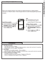
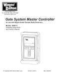
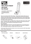
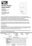
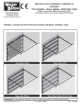
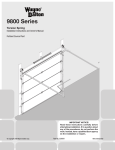
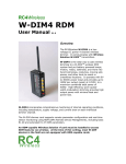
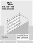
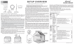
Z-Wave® enabled 3-Way
15 Amp In-Wall Switch
User Manual
For Model HA18WD
Thank you for purchasing the Z-Wave® Enabled 3-Way 15 Amp In-Wall Switch. Z-Wave® products by WayneDalton allow you to manage and control your home by remote control for convenience, comfort, safety and energy
conservation. Your Z-Wave® Enabled In-Wall Switch features 15 Amp capability for single pole or 3-way applications
such as chandeliers, foyer lights and outdoor flood lights and is a great addition to your Z-Wave® network for lighting
control. In addition to indoor and outdoor lighting switches, thermostats, security systems, garage door openers and
window shades are just a few of the items you can easily control with additional Z-Wave® certified products.
Your new Z-Wave® Enabled 3-Way In-Wall Switch is compatible with the complete range of Wayne-Dalton Z-Wave®
certified controllers and will also work with Z-Wave® certified controllers from other manufacturers and brands.
Please consult the user manual and your controller supplier for specific details.
Home Control Basics
Z-Wave® certified products will allow you to easily control multiple devices in a home with the push of a button in
what is known as a “scene”. Turning on your home’s interior lights and activating the set-back on your thermostat
from your in-vehicle remote as you come home is an example of a scene. Dimming the lights and automatically
closing your curtains to watch TV with a single push of a button is another example of a scene.
To begin using Z-Wave® Home Control technology it is helpful to understand that each Z-Wave® module, including
the Z-Wave® Enabled 3-Way In-Wall Switch, communicate with each other using a low power radio transmitter
and receiver. Large metal objects, house wiring, walls, furniture, refrigerators, microwaves and similar items can
interfere with communication between the modules to reduce the range or even prevent communication. Placement
of the Z-Wave® Enabled 3-Way In-Wall Switch and other Z-Wave® modules is very important to obtain a reliable
network.
A Z-Wave® network is a collection of Z-Wave® modules in a mesh type of network. Each Z-Wave® module,
regardless of manufacturer, communicates with other modules within range to route and repeat the signals from
one device to the next, this creates a highly reliable and robust transmission throughout the home. In addition, the
network becomes stronger as more modules are added.
A Z-Wave® network can have only one primary controller. The primary controller establishes network security to
ensure your network will not operate a neighbors network and vice-versa. It is a good practice to label and protect
your primary controller since it is the only Z-Wave® controller that can add modules to or remove modules from
your network. It is easy to add secondary controllers as your network grows. Your Z-Wave® Enabled 3-Way In-Wall
Switch can belong to only one network, and therefore only one primary controller, but it can be added to as many
secondary controllers or Z-Wave® “scenes” as you wish for added convenience.
For more tips and great ideas on how to create, set-up and use scenes for safety, security, comfort, convenience,
and expand your network please visit our web site, www.wayne-dalton.com/access.
Important Notice!
Read the enclosed instructions carefully before installing your new Z-Wave® Enabled 3-Way In-Wall Switch. Pay
close attention to all warnings and notes and carefully follow the installation steps in the order they are presented to
save time and minimize the risk of damaging the switch or the system it controls.
This manual should be retained for future reference.
1
Glossary/Warnings/Table of Contents
Table of Contents
Introduction and Z-Wave® Home Control Basics.........................................1
Table of Contents.........................................................................................2
Warnings and Glossary................................................................................2
Installation............................................................................................... 3-5
Programming/Operation/Troubleshooting.....................................................5
Technical Specifications/Compliance...........................................................6
Warning
IMPORTANT WARNINGS and SAFETY INSTRUCTIONS
1. Heed all warnings.
2. Read and follow these instructions
3. Keep these instructions for future reference.
4. If you are unsure about any part of these instructions, consult a qualified electrician or use
a qualified electrician for this installation.
5. Use this device only with copper or copper clad wire.
6. 3-Way switch applications may require an additional wire to be run, refer to the wiring
diagrams for further instruction.
7. To reduce the risk of overheating and possible damage to other equipment, do not install
to control a receptacle, a motor-operated appliance, a fluorescent lighting fixture, or a
transformer supplied appliance.
GLOSSARY
Copy – See Replicate.
Delete – Erase transmitter or scene information from Controller. Also known as Exclude.
Device – Any item that is connected to a module (for example, lamps).
Exclude – Remove a module, transmitter or scene from the controller.
Include – Add a module to the controller. Also known as Inclusion.
Module – Any Wayne-Dalton or Z-Wave® product that is controlled with a Wayne-Dalton or
Z-Wave® remote controller. A module can be part of more than one scene.
Network – A collection of Z-Wave® modules controlled by primary and secondary controllers operating
on the same system. A network has its own unique identification code so that no one else can control the
system.
Node – Single Z-Wave® endpoint (controller or module) on a network .
Primary Controller – The first controller used to set up your modules and network.
NOTE: Only the Primary Controller can be used to include or delete modules from a network. It
is recommended that you mark the primary controller for each network for ease in modifying your
network.
Replicate – Copy from one controller to another.
Scene – A scene is a series of Z-Wave® modules programmed to turn to a specific level (on, off or dim,
normal mode, save mode, etc...) with the push of a button on a controller.
Schedule - A timer based event in the software that will activate a scene or turn on/off a zone at a specified
time of day, or at sunrise or sunset.
Secondary Controller – A controller containing network information about other modules within the
network, and is created FROM the primary controller. Secondary controllers cannot include or delete
modules to the network.
2
INSTALLATION
WARNING
Installation
• ELECTRICAL SHOCK HAZARD. RISK OF INJURY OR DEATH. DISCONNECT
ELECTRICAL POWER AT SERVICE PANEL BEFORE INSTALLING AND TEST THAT
POWER IS OFF BEFORE WIRING.
• FOLLOW LOCAL ELECTRICAL CODES DURING INSTALLATION.
• FOR INDOOR USE ONLY.
1.
2: Match your wiring application to the one of the diagrams below and refer to it for the remainder of the
installation.
Single Pole Application
HOT
BLUE
LOAD
RED
WHITE
Incandescent
Lighting Load
BLACK
120VAC
50/60 Hz
NEUTRAL
BARE
COPPER
HA18WD
2 Switch/3-Way Application with Single-Pole Remote Switch Incandescent
Lighting Load
BLUE
BLACK
HOT
120VAC
50/60 Hz
NEUTRAL
BARE
COPPER
SinglePole
Switch
RED
WHITE
LOAD
HA18WD
2 Switch/3-Way Application with 3-Way Remote Switch
18 ga. MIN. (not supplied)
HOT
120VAC
50/60 Hz
BLUE
BLACK
BARE
COPPER
NEUTRAL
RED
HA18WD
3-Way
Switch
Common
120VAC
50/60 Hz
Additional wire (not supplied)
3-Way
Switch
RED
120VAC
50/60 Hz
Common
WHITE
Additional wire (not supplied)
BLACK
BLUE
BARE
COPPER
RED
NEUTRAL
HA18WD
3-Way
Switch
120VAC
50/60 Hz
NEUTRAL
4-Way
Switch
Incandescent
Lighting Load
3-Way
Switch
Common
Common
WHITE
Additional wire (not supplied)
Multi-Way Application
HOT
LOAD
3-Way
Switch
Common
HA18WD
4 Switch Application
HOT
Incandescent
Lighting Load
BLUE
BLACK
BARE
COPPER
NEUTRAL
Incandescent
Lighting Load
WHITE
3 Switch Application
HOT
LOAD
Not
Used
Incandescent
Lighting Load
BLACK
BLUE
BARE
COPPER
RED
3-Way
Switch
4-Way
Switch
4-Way
Switch
3-Way
Switch
Common
Common
WHITE
HA18WD
3
Installation
Installation (continued)
3. Trim wires to 7/16 inch as shown in the adjacent diagram.
4. Connect the BLACK wire of the HA18WD switch to the 120V HOT
building wire (the wire leading to the circuit breaker or fuse box,) using a
twist connector (provided.)
NOTE: Insert wires straight into the twist connector, the twist
clockwise. Make sure all twist connectors are tight. Secure each
twist connector with electrical tape. Verify no bare wire shows
below the wire connector.
5A. FOR SINGLE POLE APPLICATION ONLY: Connect the BLUE wire of the HA18WD to the LOAD wire using
a twist connector (provided.)
5B. FOR 2, 3, and 4 SWITCH, and MULTI-WAY APPLICATIONS: Connect the BLUE wire of the HA18WD to
the LOAD wire of the lighting load using a twist connector provided.
NOTE: An additional wire run may be necessary in multi-switch applications to connect the
HA18WD directly to the lighting load as shown in the wiring diagrams. Consult with a qualified
electrician if you are unsure about any part of the installation.
6. Connect the WHITE wire of the HA18WD to the NEUTRAL wire using a twist connector (provided.)
7. Connect the ground wire from the box to the bare copper wire on the HA18WD switch. If there is no
ground wire, connect the bare copper wire of the HA18WD to the wall box if it is metal. If the wall box is
plastic, connect the bare copper wire to ground as supplied or consult with a qualified electrician.
8A. FOR SINGLE POLE APPLICATION ONLY: Remove the semi-stripped end of the RED wire and apply the
twist connector to this wire without any connecting wire.
8B. FOR 2, 3, and 4 SWITCH, and MULTI-WAY APPLICATIONS: Connect the RED wire to the COMMON
wire (aka traveler) of the next switch in the circuit.
9. Tuck wires into wall box leaving room for the HA18WD unit. For testing purposes, partially screw
mounting screws (provided) of the HA18WD into the wall box.
10. Restore electrical power to the circuit.
11. Test switch by pressing the upper part of the rocker switch to turn the lights ON and pressing the lower
part of the rocker switch to turn the lights OFF. The lights should turn ON and OFF. If lights do not turn on,
refer to the TROUBLESHOOTING section.
12. Upon successful testing, finish mounting the HA18WD unit to the wall box with the screws provided and
install a decorator wall plate (not provided.)
4
Refer to your specific controller’s user manual for detailed instructions on adding modules
(devices) to a Z-Wave® network. Refer to diagram below for control and programming functions
of switch.
Top of Rocker switch:
A. Press and Release to turn light ON.
B. Press and Release to INCLUDE/
EXCLUDE to Network or Scene.
C. Press and Release to ADD into
Scene in ON position.
Installation/Programming
Programming/Operation
LED:
A. LED ON indicates switch is ON.
B. LED flashing indicates switch is
communicating with Z-Wave® network.
Bottom of Rocker switch:
A. Press and Release to turn light OFF.
B. Alternate) Press and Release to
INCLUDE/EXCLUDE to Network or
Scene.
C. Press and Release to ADD into
Scene in OFF position.
Troubleshooting
1.
2.
3.
Light does not turn ON:
• Lamp bulb is burned out - Replace.
• Wire connection is broken - Following all safety precautions, remove switch and check all connections.
• Circuit breaker or fuse has tripped - Reset/Replace.
Light flickers:
• Lamp bulb is not screwed in properly. - Check and tighten.
• Wire connection is intermittent - Following all safety precautions, remove switch and check connections.
Z-Wave® controller will not operate switch:
• Lamp bulb is burned out - Replace.
• Switch was programmed in the OFF position - Reprogram to ON position.
• Switch is not programmed to Network or Scene - Reprogram.
5
Compliance/Customer Support/Technical Specifications
TECHNICAL SPECIFICATIONS
•
•
•
•
For control of permanently installed incandescent lamp or compact fluorescent fixtures
Ratings: 15 Amps General Purpose, 120 VAC, 50/60 Hz
Suitable for up to 3 gang installations
Operating temperature range: 32°F - 104°F/0°C - 40°C
CUSTOMER SUPPORT
For Installation and Z-Wave programming support,
please e-mail: [email protected]
Additional product information and general information on Wayne-Dalton Home Control
products may be found on our web site at www.wayne-dalton.com/access.
FCC and IC Statement
FCC Regulatory Information:
NOTE: This equipment has been tested and found to comply with the limits for a Class B digital device, pursuant to Part 15
of the FCC Rules. These limits are designed to provide reasonable protection against harmful interference in a residential
installation. This equipment generates, uses, and can radiate radio frequency energy and, if not installed and used in
accordance with the instruction, may cause harmful interference to radio communications. However, there is no guarantee
that interference will not occur in a particular installation. If this equipment does cause harmful interference to radio or
television reception, which can be determined by turning the equipment off and on, the user is encouraged to try and correct
the interference by one or more of the following measures:
a) reorient or relocate the receiving antenna,
b) increase the separation between the equipment and receiver,
c) connect the equipment into an outlet on a circuit different from that to which the receiver is connected.
Consult the dealer or an experienced radio/TV technician for help.
IC Regulatory Information:
This Class B digital apparatus meets all requirements of the Canadian Interference Causing Equipment Regulations. Operation
is subject to the following two conditions: (1) this device may not cause harmful interference, and (2) this device must accept
any interference received, including interference that may cause undesired operation of the device.
Cet appareillage numérique de la classe B répond a toutes les exigences de l’interférence canadienne causant des règlements
d’équipement. L’opération est sujette aux deux conditions suivantes: (1) ce dispositif peut ne pas causer l’interférence nocive,
et (2) ce dispositif doit accepter n’importe quelle interférence reçue, y compris l’interférence qui peut causer l’opération peu
désirée.
WARNING: Changes or modifications to this receiver not expressly approved by Wayne-Dalton Corp. could void the user’s
authority to operate this equipment.
6
© Copyright 2008 Wayne-Dalton Corp.
Part No. 0002924 Rev. A
New 09/23/08
For Assistance, you may reach us online at www.wayne-dalton.com/access
Printed in China