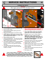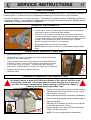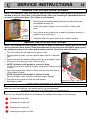
1
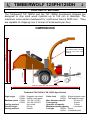
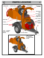
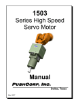
CONTENTS
Section
INTRODUCTION
PURPOSE OF MACHINE
MACHINE DIMENSIONS & SPECIFICATIONS
PARTS LOCATION DIAGRAMS
SAFE WORKING
Operator’s Personal Protective Equipment Required
Basic Woodchipping Safety
General Safety Matters - Do’s and Dont’s
Noise Test
OPERATING INSTRUCTIONS
Safe Transportation
Hitching onto the Tow Ball
Unhitching the Chipper
Delivery
Operator’s Personal Protective Equipment Required
Manual Controls
Auto Controls
Emergency Stopping
Petrol Engine Controls (125PH)
Starting the Petrol Engine
Stopping the Petrol Engine
Diesel Engine Controls
Starting the Diesel Engine
Stopping the Diesel Engine
Hydraulic Oil Lever Indicator
Petrol Tank Indicator
Daily Checks Before Starting
Before Using the Chipper
Starting to Chip
Chipping
Blockages
SERVICE INSTRUCTIONS
Service Schedule
Engine Servicing
Safe Maintenance
Spares
Battery Removal and Maintenance
Check Fittings
Change Blades
Check Hoses
Tension Drive Belt
Tension Hydraulic Pump Belts
Change Hydraulic Oil and Filter
Grease the Roller Drive Splines
Grease the Roller Box Slides
Greasing Rotor Bearings
Engine Manufacturer’s Handbook
WARRANTY STATEMENT
IDENTIFICATION PLATES
EC DECLARATION OF CONFORMITY CERTIFICATE
STICKERS
WIRING DIAGRAM 125DH
WIRING DIAGRAM 125PH
CIRCUIT DIAGRAM 125DH
CIRCUIT DIAGRAM 125PH
HYDRAULIC LAYOUT
PARTS LISTS
21st Dec 04
Page No.
1
2
2
3&4
5
5
5
6
7
8
8
8
8
9
9
9
10
10
10
10
10
11
11
11
11
11
12
12
12
13
13
14
14
15
15
15
15
16
16
16
17
17
17
18
18
18
18
19
20
21
22 & 23
24
25
26
27
28
30 - 47
TIMBERWOLF 125PH/125DH
1
INTRODUCTION
Thank you for choosing this Entec/Timberwolf brushwood chipper. Entec/Timberwolf
chippers are designed to give safe and dependable service if operated according to the
instructions.
Before using your new chipper, please take time to
read this manual which contains
IMPORTANT HEALTH AND SAFETY INFORMATION
and explains the chipper controls - failure to do so could result in :
- personal injury
- equipment damage
- damage to property
- a member of the general public becoming injured
This manual covers the operation and maintenance of both the Timberwolf TW 125PH
and the TW 125DH. All information in this manual is based on the latest product
information available at the time.
All the information you need to operate the machine safely and effectively is contained
within pages 3 to 12. Ensure that all operators are adequately trained for operating
this machine especially with regard to safe working practices.
Entec's policy of constantly improving their products may involve major or minor
changes to the chippers or their accessories. Entec Industries reserves the right to
make changes at any time without notice and without incurring any obligation.
Due to improvements in design and performance during production, in some cases
there may be minor discrepancies between the actual chipper and the text in this
manual.
The manual should be considered a permanent part of the
machine and should remain with it if the machine is resold.
Always follow safe operating and maintenance practices
!
CAUTION or WARNING
Be aware of this symbol and where shown
carefully follow the instructions
This caution symbol indicates important safety messages in this manual. When
you see this symbol be alert to the possibility of injury to yourself or others, and
carefully read the message that follows.
TIMBERWOLF 125PH/125DH
2
PURPOSE OF MACHINE
The Timberwolf TW 125PH and the TW 125DH brushwood chippers are
designed to chip solid wood material up to 125 mm in diameter. The
maximum cross-section hardwood for continuous feed is 5000 mm2. They
are capable of chipping over 2 tonnes of brushwood per hour.
DIMENSIONS
Serial No. Location
717 mm
1603 mm
2240 mm
The serial number can be
found on top of the rotor
housing.
m
5m
3
13
3163 mm (2623 mm with feed tray folded)
Timberwolf TW 125DH & TW 125PH Specification
Engine type
125DH:
125PH:
Maximum power 125DH:
125PH:
Cooling method:
Overall weight:
Starting method:
Ruggerini twin diesel
Honda v-twin petrol
14.2 kW (19 HP)
14.9 kW (20 HP)
Air cooled
570 kg
Electric
Roller feed
125DH: Single hydraulic motor
125PH: Twin hydraulic motor
Max. diameter material:
125 mm (5”)
Fuel capacity:
18 litres
Hydraulic oil capacity:
13 litres
Material processing capacity:
2 tonnes/hr
Fuel type
125DH: Diesel
125PH: Unleaded petrol
PARTS LOCATOR
SAFETY BAR
CONTROL BOX
SPARE WHEEL
3
DISCHARGE
BUCKET
DISCHARGE
TUBE
ROLLER BOX
COVER
DISCHARGE
CLAMP NUTS
BELT GUARD
FEED TRAY
ENGINE
FUNNEL
BATTERY BOX
COVER
LIGHT BOARD
125PH - SHOWING
HONDA PETROL
ENGINE
ROTOR HOUSING
125DH - AS ABOVE
BUT SHOWING
RUGGERINI DIESEL
ENGINE
HYDRAULIC
OIL TANK
HYDRAULIC
OIL FILTER
FUEL TANK
PROP STAND
BELT TENSION
ADJUSTER
ENGINE
PULLEY
ROLLER BOX
ENGINE
SHAFT
BATTERY
HYDRAULIC
PUMP
SECONDARY COUPLING
TOW HEAD
JOCKEY
WHEEL
ASSEMBLY
HYDRAULIC PUMP
BELT ADJUSTER
ROTOR DRIVE
PULLEY
CUTTER BLADE
ROTOR
FAN
PARTS LOCATOR
4
SAFE WORKING
5
WARNING
!
The chipper will feed material through on its own. To do this, it relies on
sharp blades on the chipper rotor. To keep the blades sharp, only feed the
machine with clean brushwood. DO NOT put muddy/dirty wood, roots,
potted plants, bricks, stones or metal into the chipper.
!
OPERATOR'S PERSONAL PROTECTIVE EQUIPMENT REQUIRED
Chainsaw safety helmet fitted
with visor and recommended
ear defenders to the
appropriate specifications.
Close fitting heavy-duty
non-snag clothing.
Work gloves with elasticated
wrist.
Face mask if
appropriate.
DO NOT
Safety boots.
wear
rings,
bracelets,
watches, jewellery or any
other items that could be
caught in the material and
draw you into the chipper.
BASIC WOODCHIPPING SAFETY
The operator should be aware of the following points:
MAINTAIN A SAFETY EXCLUSION ZONE around the chipper of at least 10 metres for the
general public or employees without adequate protection. Use hazard tape to identify this
working area and keep it clear from debris build up. Chips should be ejected away from any
area the general public have access to.
HAZARDOUS MATERIAL - Some species of trees and bushes are poisonous. The chipping
action can produce vapour, spray and dust that can irritate the skin. This may lead to
respiratory problems or even cause serious poisoning. Check the material to be chipped before
you start. Avoid confined spaces and use a facemask if necessary.
BE AWARE when the chipper is processing material that is an awkward shape. The material
can move from side to side in the funnel with great force. If the material extends beyond the
funnel the brash may push you to one side causing danger. Badly twisted brash should be
trimmed before being chipped to avoid thrashing in the feed funnel.
BE AWARE that the chipper can eject chips out of the feed funnel with considerable force.
Always wear full head and face protection.
ALWAYS work on the side of the machine furthest from any local danger, e.g. not road side.
SAFE WORKING
6
GENERAL SAFETY MATTERS
!
DO’S AND DONT’S
ALWAYS stop the chipper engine before making
any adjustments, refuelling, or cleaning.
DO NOT use chipper unless available light is
sufficient to see clearly.
ALWAYS check machine has stopped rotating
and remove chipper ignition key before
maintenance of any kind, or whenever the
machine is to be left unattended.
DO NOT use or attempt to start the chipper
without the feed funnel, belt guard, guards and
discharge unit securely in place.
ALWAYS check machine is well supported and
cannot move.
DO NOT start the chipper running unless properly
guarded.
ALWAYS run with the engine set to maximum
speed.
DO NOT stand directly in front of the feed funnel
when using the chipper. Stand to one side.
ALWAYS check (visually) for fluid leaks.
DO NOT allow -
ALWAYS take regular breaks. Wearing personal
protective equipment for long periods can be
tiring and hot.
ALWAYS keep hands, feet and clothing out of
BRICKS
feed opening, discharge and moving parts.
STRING
CLOTH
PLASTIC STONES
ALWAYS use the next piece of material or a push
stick to push in short pieces. Under no
circumstances should you reach into the funnel.
METAL
GLASS
RUBBER
ROOTS
BEDDING
PLANTS
- to enter the machine, as damage is likely.
ALWAYS keep the operating area clear of people,
animals and children.
DO NOT smoke when refuelling.
Petrol is explosive!
ALWAYS keep the operating area clear from
debris build up.
DO NOT let anyone who has not received
instruction operate the machine.
ALWAYS keep clear of the chip discharge tube.
Foreign objects may be ejected with great force.
ALWAYS ensure protective guarding is in place
before commencing work. Failure to do so may
result in personal injury or loss of life.
ALWAYS use chipper in a well ventilated area exhaust fumes are dangerous.
DO NOT climb on the machine at any time.
DO NOT handle material that is partially engaged
in the machine.
DO NOT touch any exposed wiring whilst
machine is running.
SAFE WORKING
7
NOISE TEST
MACHINE:
NOTES:
TW 125PH & TW 125DH
TESTED CHIPPING 65 mm X 75 mm CORSICAN PINE
1.5m IN LENGTH
Noise levels above 90dB (A) will be experienced at the working position. Wear ear protection
at all times to prevent possible damage to hearing. All persons within a 4 metre radius must
also wear good quality ear protection.
Figures shown represent readings for the 125DH, the 125PH figures are slightly lower.
90
.8d
B
Ca
u
lc
d
te
la
96.7 dB
101.9 dB
90.8dB Calculated
96.7 dB
97.5 dB
R= 4 metres
97.7 dB
at
ed
98.8 dB
B
8d
90.
C
l
cu
l
a
R= 10 metres
Guaranteed Sound Power: 125PH 120dB (A) 125DH 121dB (A)
As required by Annex III of Directive 2000/14/EC “Noise Emission in the environment by equipment for use outdoors”.
OPERATING INSTRUCTIONS
8
SAFE TRANSPORTATION
WHEN towing a chipper the maximum speed limit is 60 mph.
ON rough or bumpy road surfaces reduce speed accordingly to protect your machine from
unnecessary vibration.
WHEN towing off road be aware of objects that may catch the chipper undergear.
WHEN towing off road ensure inclination is not excessive.
AVOID excessively pot holed ground.
WHEN reversing the chipper the short wheel base will react quickly to steering.
THE chipper does not have brakes so be aware of increased braking distances.
ALWAYS check the discharge is tight before moving.
KEEP tyre pressures inflated to 1.8 bar or 26 psi.
CHECK wheel nuts are tightened to 90Nm or 65 lbs ft.
CLEAR loose chippings and debris from the machine before departing.
ENSURE the feed funnel is closed and the catches are properly engaged before departing.
HITCHING ONTO THE TOW BALL
CHECK the ball head is well greased.
WIND jockey wheel assembly anticlockwise until the tow head is above the height of the ball
hitch on the vehicle.
REVERSE the vehicle so the ball hitch is directly below the tow head.
ATTACH the secondary coupling to a strong point on the vehicle, not the ball hitch.
ENSURE the barrel lock is retracted from the tow head.
GRASP handle on tow head and push back catch with thumb.
WIND the jockey wheel assembly clockwise, so lowering the tow head onto the ball hitch.
RELEASE handle and continue to wind jockey wheel clockwise. The tow head should snap
into place on the ball hitch. If it doesn't repeat previous 2 steps.
WIND jockey wheel up until fully retracted and the jockey wheel frame is seated in its notch on
the stem. The chipper weight should be fully on the vehicle.
RELEASE the jockey wheel clamp and slide the jockey wheel assembly fully up.
TIGHTEN clamp on the jockey wheel assembly.
CONNECT electrical plug to socket on rear of towing vehicle and check operation of all the
trailer and vehicle lights.
INSERT the barrel lock for security.
THE chipper is now properly attached to the vehicle.
UNHITCHING THE CHIPPER
ENSURE the chipper will not roll away after being disconnected from the vehicle. Use the
chocks provided if in doubt.
DISCONNECT the electrical cable from the vehicle socket.
RELEASE the barrel lock.
RELEASE secondary coupling.
RELEASE the jockey wheel assembly clamp.
LOWER the jockey wheel assembly fully.
RETIGHTEN the jockey wheel assembly clamp.
WIND the jockey wheel assembly anticlockwise until it starts to take the weight of the chipper.
GRASP the handle and release the catch with your thumb.
CONTINUE to wind the jockey wheel anticlockwise. This should lift the tow head clear of the ball hitch.
DRIVE the vehicle clear of the chipper.
WIND the jockey wheel assembly to a suitable point where the chipper is level.
THE chipper is now fully detached from the vehicle.
OPERATING INSTRUCTIONS
9
DELIVERY
All Timberwolf TW 125 machines have a full pre - delivery inspection before leaving the factory and
are ready to use. Read and understand this instruction manual before attempting to operate the
chipper. In particular, read pages 5-7 which contain important health and safety information and advice.
OPERATOR’S PERSONAL PROTECTIVE EQUIPMENT REQUIRED
CHAINSAW safety helmet fitted with visor and
recommended ear defenders to an appropriate
specification.
HEAVY-DUTY work gloves with elasticated wrist.
CLOSE - FITTING heavy-duty non-snag clothing.
SAFETY footwear.
FACE MASK (if appropriate).
See page 5 for more detailed information.
MANUAL CONTROLS
Roller control box - is the control box above the feed opening of the chipper funnel. Its function is to control
the feed rollers. The feed rollers draw material into the machine. It does not control the main rotor.
RED SAFETY BAR = This is the large red bar that surrounds the feed tray and side of the feed funnel.
The bar is spring loaded and connected to a switch that will interrupt the power to the rollers. The
switch is designed so that it only activates if the bar is pushed to the limit of its travel. The rollers stop
instantly, but can be made to turn again by pressing either the GREEN FEED or BLUE REVERSE
control buttons.
RED SAFETY BAR TEST
To ensure the SAFETY BAR is always operational it must be activated once before each work
session. The rollers will not function until the bar is activated. This procedure must be repeated
each time the ignition is switched off.
GREEN BUTTON = Forward feed - Push the button once - this activates the rollers and will allow you
to start chipping (if the rotor speed is high enough).
RED BUTTON = Emergency stop - This button stops the rollers from feeding. It overrides all other
buttons or bars and will not allow the other buttons to function until it has been reset.
To reset, pull or twist (depending on style of button) until it returns to its original position. The forward
and reverse buttons will now function.
BLUE BUTTON = Reverse feed - allows you to back material out of the rollers. The rollers will only
turn in reverse as long as you keep pressing the button. You do not have to press the STOP button
before pressing the GREEN FEED button to recommence feeding.
Control Panel Diagram
RED STOP FEED EMERGENCY STOP
BUTTON
GREEN FORWARD
FEED BUTTON
BLUE REVERSE
FEED BUTTON
RED SAFETY BAR
Do not rely on the red bar to keep the rollers stationary if it is
necessary to clear or touch the rollers. Always switch off the
machine and remove ignition key before approaching the rollers.
OPERATING INSTRUCTIONS
10
AUTO CONTROLS
The speed control unit controls the feed rate of the material going into the chipping chamber. If the
rotor speed is below the predetermined level the speed control unit will not allow the feed rollers to
work in either forward or reverse until the rotor speed rises above the predetermined level, at which
point the feed rollers will start turning without warning.
EMERGENCY STOPPING
Push the RED STOP button or push the RED SAFETY BAR
(whichever is the quickest for you to reach). Turn off the engine ignition key.
The emergency stop will prevent any more material being fed into the chipper. The rotor will still be
turning. The engine must be powered down to stop the rotor.
PETROL ENGINE CONTROLS (125PH)
This label indicates the speed setting of
the chipper. With the throttle lever in
the fast position (hare) the machine is
ready to chip.
When the machine is not in use for
short periods of time move the lever to
the idle position (tortoise) or turn off
completely.
ON
OFF
FAST
O
1
START
SLOW
STARTING THE PETROL ENGINE (125PH)
CHOKE
STARTER
SWITCH
THROTTLE LEVER
FOR A COLD ENGINE:
Place the throttle control at 1/3 throttle and pull the
choke out.
Insert ignition key into starter switch.
Turn the key to start the engine. Release the key as
soon as the engine starts.
Gradually return the choke to the off position as the
engine starts and warms up. Allow the engine to warm
up for at least one minute before chipping.
FOR A WARM ENGINE:
Follow the instructions for a ‘cold engine’ but return the
choke to the off position as soon as the engine starts.
If engine fails to start after 10 seconds leave
for 1 minute and try again.
STOPPING THE PETROL ENGINE (125PH)
SET engine to idle position.
ALLOW to run for at least one full minute.
SWITCH off and remove ignition key.
For more detailed information refer to the Engine Owner’s Manual
OPERATING INSTRUCTIONS
11
DIESEL ENGINE CONTROLS (125DH)
The Ruggerini engines are not fitted with a throttle or preheat mechanism. They are designed to
run at working speed at all times.
STARTING THE DIESEL ENGINE (125DH)
Start Button
Y ON
H
TO S
R
PU S
P
TO
GINE S
EN
If engine fails to start after 10 seconds leave for
1 minute and try again.
Battery Isolator Switch
B AT T E
STOPPING THE DIESEL ENGINE (125DH)
TURN the battery isolator switch to the 'OFF' position.
For more detailed information refer to the Engine Owner’s Manual
HYDRAULIC OIL LEVEL INDICATOR
The oil level will be visible through the tank wall.
It should be within the upper and lower arrows
PETROL TANK INDICATOR
The fuel level may be inspected by removing the fuel filler cap and looking into the tank. A
graduated plate will indicate the level.
RT
TA
TURN the battery isolator switch to the 'ON' position.
PUSH the 'START' button until the engine begins to fire.
RELEASE the 'START' button.
ALLOW the engine to warm up for 1 minute before starting chipping
OPERATING INSTRUCTIONS
12
DAILY CHECKS BEFORE STARTING
LOCATE the machine on firm level ground.
CHECK machine is well supported and cannot move.
CHECK jack stand is lowered and secure.
CHECK all guards are fitted and secure.
CHECK the discharge unit is in place and fastened securely.
CHECK discharge tube is pointing in a safe direction.
CHECK the feed funnel to ensure no objects are inside.
CHECK feed tray is in up position - to prevent people reaching rollers.
CHECK controls as described below.
CHECK (visually) for fluid leaks.
CHECK fuel and hydraulic oil levels.
For parts location see diagrams on pages 3 & 4.
BEFORE USING THE CHIPPER
IT IS ESSENTIAL TO CARRY OUT THE FOLLOWING TESTS to check safety equipment - this sequence
of tests will only take a few seconds to carry out. We recommend that these tests are carried out daily.
Observing the function as described will confirm that the safety circuits are working correctly. This is also a
good opportunity to remind all operators of the control and emergency stop systems.
WITH THE ENGINE RUNNING AT FULL SPEED
1
PRESS THE RED
BAR TO POWER
THE CONTROL
SYSTEM
5
PRESS THE GREEN
BUTTON AGAIN
THE ROLLERS SHOULD
RUN
2
4
3
PRESS THE GREEN
BUTTON
THE ROLLERS
SHOULD RUN
PRESS THE RED BAR
THE ROLLERS SHOULD
STOP
PRESS THE BLUE BUTTON
THE ROLLERS SHOULD TURN
BACKWARDS ONLY WHILE THE
BUTTON IS PRESSED
6
7
PRESS THE EMERGENCY
RED BUTTON
THE ROLLERS SHOULD
STOP
PRESS THE BLUE
BUTTON
THE ROLLERS
SHOULD NOT TURN
8
TWIST TO RESET
THE RED BUTTON
THE MACHINE IS READY
TO USE
STARTING TO CHIP
!
WARNING
Do not use or attempt to start the chipper without the
protective guarding and discharge unit securely in place.
Failure to do so may result in personal injury or loss of life.
CHECK that the chipper is running smoothly.
RELEASE the catches on the feed tray and lower. Turn to release the red stop button.
PRESS the green control button. The rollers will commence turning.
STAND to one side of the feed funnel.
PROCEED to feed material into the feed funnel.
!
OPERATING INSTRUCTIONS
13
CHIPPING
Wood up to the recommended diameter can be fed into the feed funnel. Put the butt end in first and
engage it with the feed roller. The hydraulic feed rollers will pull the branch into the machine quite
quickly. Large diameter material will have its feed rate automatically controlled by the speed control
unit.
Sometimes a piece of wood that is a particularly awkward shape is too strong for the feed rollers to
break. This will cause the top roller to either bounce up and down on the wood or both rollers to stall.
If this occurs press the BLUE REVERSE button until the material has been released. Pull the material
out of the feed funnel and trim it so the chipper can handle it.
Both feed rollers should always turn at the same speed. If one or both rollers stop or suddenly slow
down it may be that a piece of wood has become stuck behind one of the rollers. If this occurs press
the BLUE REVERSE button and hold for 2 seconds - then repress GREEN FEED button. This should
enable the rollers to free the offending piece of material and continue rotating at the correct speed. If
the rollers continue to stall in the 'forward feed' or 'reverse feed' position push the RED STOP
BUTTON, turn the engine off, remove the ignition key and investigate.
BLOCKAGES
Always be aware that what you are putting into the chipper must come out. If the chips stop coming
out of the discharge tube but the chipper is taking material in - STOP IMMEDIATELY. Continuing to
feed material into a blocked machine may cause damage and will make it difficult to clear.
If the chipper becomes blocked proceed as follows:
STOP the engine and remove the ignition keys.
REMOVE the discharge tube. Check that it is clear.
WEARING gloves, reach into the rotor housing and scoop out the debris causing the blockage.
!
WARNING
Do not reach into the rotor housing with unprotected hands. There are
sharp blades and any small movement of the rotor may cause serious injury.
!
REPLACE the discharge tube.
RESTART the engine and increase to full speed.
ALLOW machine time to clear excess chips still remaining in rotor housing before you
continue feeding brushwood. Feed in a small piece of wood whilst watching to make sure
that it comes out of the discharge. If this does not clear it, repeat the process and carefully
inspect the discharge tube to find any obstruction.
NOTE:
Continuing to feed the chipper with brushwood once it has become blocked will cause the chipper to
compact the chips in the rotor housing and it will be difficult and time consuming to clear.
AVOID THIS SITUATION - WATCH THE DISCHARGE TUBE AT ALL TIMES.
SERVICE INSTRUCTIONS
14
WARNING
ALWAYS IMMOBILISE THE MACHINE BY STOPPING THE ENGINE,
REMOVING THE IGNITION KEY AND DISCONNECTING THE BATTERY BEFORE
UNDERTAKING ANY MAINTENANCE WORK.
Daily
Every
Every
Every
Every
Every
Table 1. Service Schedule
Check
25
50
100
200
500
Hours
Hours
Hours
Hours
Hours
Complete the following tasks:
!
Check engine oil - top up if necessary.
Check for engine oil/hydraulic oil leaks.
Check fuel level.
Check feed funnel, feed roller cover,
access covers, bonnet and discharge unit
are securely fitted.
Ensure engine air intake in bonnet is free
from leaf build up.
Check tyre pressure is 26 - 28 psi.
Check and adjust if necessary belt
tension.
Grease the roller drive splines.
Clean air filter element.
Check for tightness all nuts, bolts and
fastenings making sure nothing has
worked loose.
After the first 25 hours then:
Check fuel pipes and clamp bands.
Change engine oil.
Refer to Engine Owner’s Manual
Check battery electrolyte level.
Replace engine oil filter cartridge.
Refer to Engine Owner’s Manual
Replace spark plugs.
Refer to Engine Owner’s Manual
Check valve clearance.
Refer to Engine Owner’s Manual
Replace hydraulic oil filter - every year or
100 hours after service or repair work to
the hydraulic system.
Replace hydraulic oil.
Check for loose electrical wiring.
Replace fuel pipes and clamp bands.
Axle & Tow head maintenance
Refer to Engine Owner’s Manual
Refer to Suppliers Information Sheet
NOTE: Main Rotor Bearings are sealed for life. No greasing or lubrication is necessary.
!
Every
Year
SERVICE INSTRUCTIONS
15
ENGINE SERVICING
Ensure servicing is performed in accordance with the Engine Manufacturer’s Handbook.
SAFE MAINTENANCE
ALWAYS IMMOBILISE THE ENGINE BEFORE UNDERTAKING ANY MAINTENANCE
WORK ON THE CHIPPER BY REMOVING THE KEY AND DISCONNECTING THE BATTERY.
HANDLE blades with extreme caution to avoid injury. Gloves should always be worn when
handling the cutter blades.
AVOID contact with hydraulic oil.
THE drive belts should be connected while changing blades, as this will restrict sudden
movement of the rotor.
THE major components of this machine are heavy. Lifting equipment must be used for
disassembly.
CLEAN machines are safer and easier to service.
SPARES
Only fit genuine Entec replacement blades, screws and chipper spares. Failure to do so will
result in the invalidation of the warranty and may result in damage to the chipper, personal
injury or even loss of life.
BATTERY REMOVAL AND MAINTENANCE
WARNING
Refer to the battery leaflet for safety and COSHH requirements.
!
!
1.
Remove the four M8 screws that retain the battery box top.
2.
Remove the negative lead first and then the positive lead.
3.
Clean, charge and/or top up the battery as required.
4.
Refitting is the reverse of removal. Apply a smear of petroleum jelly to the terminals to
prevent corrosion.
CHECK FITTINGS
The Timberwolf TW 125PH & TW 125DH are subject to large vibrations during the normal course of
operation. Consequently there is always a possibility that nuts and bolts will work themselves loose.
It is important that periodic checks are made to ensure the security of all fasteners. Fasteners should
be tightened using a torque wrench to the required torque (see below).
General
General
General
Size
Pitch
Head
Torque Ibft
Torque Nm
M8
M10
M12
Standard
Standard
Standard
13 mm Hex
17 mm Hex
19 mm Hex
17
34
60
23
46
80
SERVICE INSTRUCTIONS
16
CHANGE BLADES
WARNING
Wear riggers gloves for the blade changing operation.
!
!
7
5
8
3
3
9
Diagram
shows 125PH
- Petrol version
4
6
1. Turn the chipper off and remove the ignition keys.
2. Remove battery leads.
3. Remove bolt and washer retaining roller box
guard and lift guard.
4. Remove the two springs on the roller box slide.
5. NOTE: Rollerbox slide weighs in excess of 20kg.
Lift the roller box slide and wedge a suitably sized
piece of wood to hold in place.
6. Remove blade access cover.
7. Remove discharge tube. Turn the rotor by hand
by grasping fan section on rear of rotor disc until
blade is visible through aperture.
8. Use a small screwdriver to remove sap and debris
from Torx socket in screw - be particularly
careful to ensure every last piece has been
removed.
9. Undo blade screws using Torx socket drive
provided. Rotor will turn until Torx socket has
located on machine.
!
10
10. Before fitting replacement blades carefully
clean blade recess in rotor so that no
debris is trapped between blade and rotor.
11. When fitting blades replace any damaged
screws with new and coat each screw with
copperslip over the whole of the thread.
12. Retighten each screw to 60Nm (45lbs ft).
NOTE: This torque setting is vitally
important to ensure your bolts come out
at a later date and Entec recommend you
purchase a torque wrench for this and
other jobs on the chipper.
13. Grease all surfaces of the roller box sliding
mechanism (see diagram on page18).
14. Replace blade access cover.
15. NOTE: Rollerbox slide weighs in excess of 20kg.
Remove wedge, lower roller box slide and
replace springs.
16. Close roller box guard and ensure bolt and
washer are tightened.
17. Refit battery leads.
WARNING
Always sharpen blades on a regular basis. Failure to do so will
cause the machine to under perform and will overload engine and
bearings causing machine breakdown. Blades must not be
sharpened beyond the wear mark (see diagram). Failure to comply
with this could result in machine damage, injury or loss of life.
!
WEAR
MARK
SERVICE INSTRUCTIONS
17
CHECK HOSES
All the hydraulic hoses should be regularly inspected for chafing and leaks. The hydraulic system is
pressurized to 130 Bar and thus the equipment containing it must be kept in good condition.
Identify the hoses that run to the top motor. These have the highest chance of damage as they are
constantly moving. If any hydraulic components are changed new seals should be installed during
reassembly. Fittings should then be retightened.
TENSION DRIVE BELTS
1. Remove side panel.
2. Loosen bolt in centre of tensioner pulley with a 19 mm spanner so
that pulley is able to slide with minimal wobble.
3
3. Turn nut in end of tensioner pulley slider until correct belt tension
is achieved and lock the tensioner pulley bolt back up again. Tension
is correct when 4.5kg of force deflects one belt 6 mm at the centre of
its span. (Push the belt firmly with your index finger; it should
deflect to roughly the depth of your fingernail).
4. Run machine and test, recheck belt tension.
2
5. NOTE: Slack drive belts will cause poor performance and belt / pulley
wear.
TENSION HYDRAULIC PUMP BELT
1. Remove belt guard.
2. Access the two nuts on the under side of the chassis and slacken
using a 19 mm socket spanner.
3. Adjust the M8 bolt on the outside plate until the desired tension is
achieved. Tension is correct when 4.5kg of force deflects one belt
6 mm at the centre of its span. (Push the belt firmly with your
index finger, it should deflect to roughly the depth of your fingernail).
4. Retighten the two nuts to (80 Nm) 60 lbs/ft.
3
2
5. Refit belt guard.
CHANGE HYDRAULIC OIL AND FILTER
!
WARNING
Use plastic gloves to keep oil off skin and dispose of the used oil and filter in an
ecologically sound way. The oil and filter should be changed once a year or at
any time it becomes contaminated. Before starting check that the chipper is
standing level and brush away loose chips.
!
1. Remove the screw cap from the top of the filter housing.
2. Partially remove filter element from inner cup. Leave
filter to drain for 15 minutes.
1
3. Remove filter element from cup when clear of hydraulic oil.
4. Remove drain plug and drain oil into a suitable container.
5. Replace drain plug.
6. Refill with VG 32 hydraulic oil until the level is half way
up the sight glass (about 15 litres).
2
4
7. Replace the filter cup, install a new filter element and
replace the filter cap (screw).
8. NOTE: This is a non-adjustable air breather filter.
SERVICE INSTRUCTIONS
18
GREASE THE ROLLER DRIVE SPLINES
NOTE: This should be done four times a year or every 50 hours. If the grease in the splines is
allowed to dry out, rapid wear of the roller splines will occur resulting in a breakdown and the
need to fit replacement parts. This failure is not warranty.
1. Remove bolt and washer retaining roller box guard and lift guard
(see diagram on page 16).
2. Locate two grease nipples; one in the centre of each roller
shaft.
2
Diagram
shows 125PH
- Petrol version
3. Use a pump action grease gun to apply a generous amount of
grease to each roller drive.
4. Close the roller box guard and refit the washer and bolt.
GREASE THE ROLLER BOX SLIDES
NOTE: This should be done regularly. In dirty or dusty conditions or during periods of hard
work it should be done weekly. If the slides become dry the top roller will tend to hang up and
the pulling-in power of the rollers will be much reduced. Excessive wear will ensue.
1. Turn the chipper off and remove the ignition keys.
2. Remove battery leads - ensure machine has come to a complete
stop.
3. Remove the bolt and washer retaining roller box guard and lift guard.
4. Remove the two springs on the roller box slide.
5. NOTE: Rollerbox slide weighs in excess of 20kg.
Lift the top roller and wedge a suitably sized piece of wood to hold
in place.
6. Apply thin grease with a brush to each slide on roller box and on
inner cheeks of slider.
7. NOTE: Rollerbox slide weighs in excess of 20kg.
Remove wedge, lower roller box slide and replace springs.
8. Close roller box guard and refit bolt and washer.
9. Refit battery leads.
5
6
3
4
Diagram shows 125PH - Petrol version
GREASING ROTOR BEARINGS
Both front and rear bearings are sealed and do not need greasing.
ENGINE MANUFACTURER’S HANDBOOK
Refer to your Engine Manufacturer’s Handbook for detailed instructions on the following:
Changing the fuel filter.
Checking the engine oil.
Changing the engine oil.
Changing the engine oil filter.
TIMBERWOLF 125PH/125DH
19
ENTEC 12 MONTH CHIPPER WARRANTY
WARRANTY PERIOD
The warranty period for the woodchipper commences on the date of sale to the first end user and
continues for a period of 12 months.
This guarantee is to the first end user only and is not transferable except when an authorised
Timberwolf Dealer has a woodchipper registered with Entec Industries as a hire chipper or long term
demonstrator – in these situations they are duly authorised to transfer any remaining warranty period
to their first end user. Any warranty offered by the Timberwolf Dealer beyond the original 12 month
period will be wholly covered by said Dealer.
LIABILITY
Our obligation under this warranty is limited to repair at Entec Industries premises or at our option an
Entec approved Timberwolf dealer. No liability will be accepted for special, indirect, incidental, or
consequential loss or damages of any kind.
WARRANTY STATEMENT
Entec Industries warrants to the first end user that;
-Your woodchipper shall be designed, built and equipped, at the point of sale, to meet all current
applicable regulations.
-Your chipper shall be free from manufacturing defects both in materials and workmanship in
normal service for the period mentioned above.
Warranty will not apply to a failure where normal use has exhausted the life of a component.
Engine units are covered independently by their respective manufacturer warranties.
OWNERS WARRANTY RESPONSIBILITIES
As the owner of an Entec woodchipper you are responsible for the following;
-Operation of the woodchipper in accordance with the Entec instruction manual.
-Performance of the required maintenance listed in your Entec instruction manual.
-In the event of a failure the Entec authorised Timberwolf dealer is to be notified within 10 days of
failure and the equipment is to be made available for unmolested inspection by the dealer technician.
WARRANTY RESTRICTIONS
The Entec warranty is restricted to the first end user only and is not transferable except when an
authorised Timberwolf Dealer has a woodchipper registered with Entec Industries as a hire chipper or
long term demonstrator – in these situations they are duly authorised to transfer any remaining
warranty period to their first end user.
The Entec warranty may be invalidated if any of the following apply;
-The failed parts or assembly is interfered with in any way.
-Normal maintenance in accordance with that set out in the Entec manual has not been performed.
-Incorrect reassembly of components.
-The machine has undergone modifications not approved in writing by Entec Industries.
-In the case of tractor driven equipment, use has been on an unapproved tractor.
-Conditions of use can be deemed abnormal.
-The machine has been used to perform tasks contrary to those stated in the Entec instruction manual.
WARRANTY SERVICE
To obtain warranty service please contact your nearest Entec approved Timberwolf dealer. To obtain
details of the nearest facility please contact Entec Industries at the address on the front of this manual.
These warranty terms are in addition to and not in substitution for and do not affect any right and
remedies which an owner might have under statute or at common law against the seller of the goods
under the contract by which the owner acquired the goods.
TIMBERWOLF 125PH/125DH
20
TIMBERWOLF 125PH/125DH
IDENTIFICATION PLATES
E
A
X
P
M
E
L
ENTEC INDUSTRIES LTD
CE PLATE
ENTEC UK
STOWMARKET, SUFFOLK IP14 5AY
Date of Manuf.
Serial No.
Trailer Type
Equip. Fitted
Nominal Pwr.
Gross Weight
E
A
X
P
M
E
L
CHASSIS IDENTIFICATION PLATE
21
STICKERS
TIMBERWOLF
22
1136
(Diesel models only)
X2
121
4099
X2
PUSH TO STOP
1399
!
616
Vo i d
DO NOT USE HOIST HOOK DIRECTLY ON LIFTING EYE.
USE CORRECTLY RATED SAFETY SHACKLE
ONLY THROUGH LIFTING EYE.
2949
LIFTING EYE TO BE INSPECTED EVERY 6 MONTHS
OR BEFORE EACH USE.
670
120
92
EARS
EYES
HANDS
AX
850
HEAD
KG M
1849
dB
!! ATTENTION !!
1661
1363
dB
L WA
3004
ALWAYS VISUALLY INSPECT LIFTING EYE PRIOR TO
EACH USE. DO NOT USE LIFTING EYE IF DAMAGED.
GREASE ROLLER
SPINDLE AND
SLIDES
L WA
1522
LIFTING EYE IS DESIGNED TO LIFT THE
MACHINE’S WEIGHT ONLY.
IF BROKEN
dB
(Petrol models only)
HOT
EXHAUST
! SAFETY NOTE !
1645
y
W
DO NOT PULL HERE
arrant
L WA
1523
CLEAN UNDER BLADES BEFORE
REFITTING OR TURNING
FAILURE TO DO SO MAY RESULT IN
BLADE(S) COMING LOOSE AND DAMAGE
BEING CAUSED TO THE ROTOR HOUSING
3022
1157
LL
(Diesel models only)
ET
PU
T
PU S
TO ST
SH
OP
PU
RY O
S
INE TO
TE
N
EN
G
P
1496
TO S
RT
TA
H
BA
1494
TO R E S
671
DANGER
DANGER
R
O
EF
DANGER
!
DANGER
!
G
PA
T
X
E
EN
SE
DANGER
!
L
!
!
I
TA
E
D
DANGER
!
DANGER
!
2800
DANGER
!
617
HIGH
VELOCITY
DISCHARGE
KEEP CLEAR!
Last Updated 1st Sept 04
2801
1662
2802
OPERATING INSTRUCTIONS
READ THE INSTRUCTION MANUAL.
THE INSTRUCTION MANUAL WITH THIS MACHINE
CONTAINS IMPORTANT OPERATING, MAINTENANCE AND
HEALTH AND SAFETY INFORMATION.
FAILURE TO FOLLOW THE INFORMATION CONTAINED IN
THE INSTRUCTION MANUAL MAY LEAD TO DEATH OR
SERIOUS INJURY.
!
!
!
!
DO NOT OPERATE
WITHOUT THIS
COVER IN PLACE
DANGER
DO NOT OPERATE
WITHOUT THIS
COVER IN PLACE
DANGER
DO NOT OPERATE
WITHOUT THIS
COVER IN PLACE
DANGER
DO NOT OPERATE
WITHOUT THIS
COVER IN PLACE
DANGER
!
STOP ENGINE AND REMOVE
KEY BEFORE REMOVING
DISCHARGE UNIT. ROTATING
BLADES INSIDE.
DANGER
!
!
DO NOT USE THIS MACHINE
WITHOUT THE DISCHARGE UNIT
FITTED FAILURE TO COMPLY
MAY RESULT IN SERIOUS
INJURY OR DAMAGE
DANGER
ROTATING
BLADES
CAUTION
DO NOT PUT ROAD
SWEEPINGS IN MACHINE
AS GRIT WILL DAMAGE
BLADES
DANGER
ALLOW ENGINE TO COOL FOR
1 MINUTE BEFORE REFUELING.
USE UNLEADED PETROL
CAUTION
WHEN TRANSPORTING
DISCHARGE CLAMPS MAY
WORK LOOSE.
CHECK FREQUENTLY
CAUTION
AVOID STANDING DIRECTLY IN
FRONT OF FEED FUNNEL TO
REDUCE EXPOSURE TO NOISE,
DUST AND RISK FROM EJECTED
PARTICLES
RISK OF FIRE
FUEL HERE
!
AUTOFEED SYSTEM FITTED.
ROLLERS MAY TURN WITHOUT
WARNING!
WHEN ENGINE IS SWITCHED OF
THE ROLLERS WILL TURN
DURING THE RUN DOWN
PERIOD
DANGER
STICKERS
23
671
NN
CC
NN
CO
O
N
Forward
GREEN
Control
Box
YELLOW
PURPLE
WHITE
Y
P
W
O
ORANGE
BL/G BLUE WITH GREEN TRACER
G/B GREEN WITH BLACK TRACER
BL/R BLUE WITH RED TRACER
RED
GREEN
R
G
B
BLACK
BL BLUE
BR BROWN
KEY TO WIRING
Stop
Reverse
Y
RED
BLUE
WR1407
P
BL/G
G/B
BL
W
A
BL/R
A
B
B
C 3
C 3
NC NO
WR1406
86
85
85
86
Forward
Relay
87
30
Safety
Relay
87
30
O
D
C
A
C
A
B
D
B
4
4
P
No Stress
Sensor
EL1659
Reverse
Solenoid
W
WR242
BR
Forward
Solenoid
BL
B
R
2
A
B
B or G/Y
2
A
B
EL1419
No Stress Bypass
C
B
3
A
2
A
B
YY
Regulator
Rectifier
BR
R
BL
Kill
BL
BR
C
B
3
A
No Stress
Unit
W
B or G/Y
Y
BR
2
Alt
A
12V Battery
B
Engine Earth Point
R
R
M
Starter Motor
WR1480
R
Start
BL
Pull
Fuel
Solenoid
Hold
R
WIRING DIAGRAM 125DH
24
PURPLE
WHITE
GREEN WITH BLACK TRACER
G/B
O
ORANGE
BL/G BLUE WITH GREEN TRACER
BL/R BLUE WITH RED TRACER
YELLOW
Y
BROWN
RED
GREEN
BR
R
G
Control
Box
P
W
BLUE
BL
O
N
Forward
GREEN
KEY TO WIRING
CC
CO
BLACK
NN
NN
B
Stop
Reverse
Y
RED
BLUE
WR1407
BL
P
BL/G
G/B
W
C 3
A
B
BL/R
C 3
A
NO
B
NC
WR1406
86
85
85
86
Forward
Relay
87
30
Safety
Relay
87
30
O
C
A
C
A
B
D
D
B
4
4
No Stress
Sensor
EL1659
Reverse
Solenoid
W
WR242
P
BR
Forward
Solenoid
BL
B
R
B
A
2
B or G/Y
2
B
A
EL1419
No Stress Bypass
B
C
C
B
3
A
A
B
A
B
3
A
2
2
B/Y
B
No Stress
Unit
Engine
Earthing
Point
WR1401
Honda
BL
W
Y
BR
Engine Loom
R
B/Y
WIRING DIAGRAM 125PH
25
BLUE
RED
GREEN
Y
Control
Box
REVERSE
N/O
N/C
N/O
FORWARD
N/C
N/C
STOP
REVERSE
N/O
N/C
W
BL/R
BR
87
86
87
86
Forward
Relay
Reverse
Solenoid
B/G
BL/G
85
30
Safety
Relay
85
30
O
Forward
Solenoid
P
BL
BR
R
Kill
No Stress
Sensor
BL
R B
N/O
BL
No Stress
Unit
Alt
YY
Regulator
Rectifier
12V
Battery
R
R
M
Starter Motor
BR
B
Start
BL
Pull
BLACK WITH GREEN TRACER
KEY TO WIRING
BL/G BLUE WITH GREEN TRACER
BL/R BLUE WITH RED TRACER
B/G
ORANGE
R
G
O
BROWN
RED
GREEN
BR
YELLOW
PURPLE
WHITE
BLUE
BL
Y
P
W
BLACK
B
Fuel
Solenoid
Hold
R
CIRCUIT DIAGRAM 125DH
26
BLUE
RED
GREEN
Y
Control
Box
REVERSE
N/O
N/C
N/O
FORWARD
N/C
N/C
STOP
REVERSE
N/O
N/C
W
BL/R
86
87
86
87
BR
Forward
Relay
Reverse
Solenoid
B/G
BL/G
85
30
Safety
Relay
85
30
O
Forward
Solenoid
P
BL
No Stress
Sensor
No Stress
Unit
R B
N/O
B
To Honda Engine
Loom +12V
BLACK WITH GREEN TRACER
BL/G BLUE WITH GREEN TRACER
BL/R BLUE WITH RED TRACER
B/G
ORANGE
RED
GREEN
R
G
O
BROWN
BR
YELLOW
PURPLE
WHITE
BLUE
BL
Y
P
W
BLACK
B
KEY TO WIRING
CIRCUIT DIAGRAM 125PH
27
HYDRAULIC LAYOUT 125DH
TANK
FILTER
HY2750
PUMP
HY1421
HY1420
DCV
HY1422
HY1423
MOTOR
28
HYDRAULIC LAYOUT 125PH
TANK
FILTER
HY2750
PUMP
HY1421
HY1420
DCV
HY1423
HY1422
MOTOR
MOTOR
HY323
29
TIMBERWOLF
TW 125PH
& TW 125DH
PARTS LISTS
The following illustrations are for parts identification only.
The removal or fitting of these parts may cause a hazard and
should only be carried out by trained personnel.
Page No.
BELT TENSIONER
31
CHASSIS
32
CONTROL BOX
33
DISCHARGE
34
DRIVE TRAIN
35
ELECTRICAL LAYOUT (125DH)
36
ELECTRICAL LAYOUT (125PH)
37
ENGINE - DIESEL (125DH)
38
ENGINE - PETROL (125PH)
39
FUNNEL
40
HYDRAULICS (125DH)
41
HYDRAULICS (125PH)
42
ROLLER BOX - DOUBLE (125PH)
43
ROLLER BOX - SINGLE (125DH)
44
ROTOR
45
ROTOR HOUSING
46
STICKERS
47
BELT TENSIONER
31
11
10
9
8
7
5
6
3
4
3
2
1
Date Last Modified: 30th July 01
Item
Part No
Part Name
Q’ty
1
0313
M12/100 Bolt
1
2
0415
Heavy Washer
1
3
0491
Bearing
2
4
0411
Pulley
1
5
0472
Pulley Boss
1
6
N/A to purchase
Slider
1
7
0469
Slider Block
1
8
1342
End Plate
1
9
0711
M8 C Washer
1
10
0476
Plain M8 Nut
1
11
0342
M8/110 Bolt
1
Date Last Modified: 8th Dec 04
Item
1
2
3
4
5
6
7
8
9
10
11
12
13
14
15
16
17
0764
0084
0346
0197
0714
0162
0479
1350
Part No
1247
0445
1384S
1872/1566
1372
1373
1385S
2813
1
46
48
31
5
47
Part Name
Q’ty
Prop Stand
1
Light Board
1
Trailer Board
1
Fuel Tank-Petrol/Diesel Version 1
Beam N/S
1
Beam O/S
1
Tank Support
1
Tank Top
1
M6/12 Bolt
11
Battery Box 1/2 Section
2
Jockey Wheel Assy Complete
1
M8/20 Bolt
8
Jockey Clamp Assy
1
M8 Penny Washer
4
Head Lock It
1
M8 P Nyloc Nut
8
Tow Hitch
1
2
3
47
4
8
30
9
6
29
Item
18
19
20
21
22
23
24
25
26
27
28
29
30
31
32
33
34
27
7
28
34
33
33
40
45
40
36
35
10
31
37
45
44
22
23
24
12 31
14
34
Part Name
Q’ty
Secondary Coupling
1
Skid Plate
1
Wheel Choc
2
Choc Holster
2
Wheel
(inc.spare)
3
Mudguard
2
Mudguard Support
2
Axle
1
Fuel Tank Cap
1
Prop Support
1
M10/25 Bolt
4
M10 A Washer
4
M6 C Washer
11
M8 C Washer
14
M12/35 Bolt
4
M12 C Washer
23
M12/40 Bolt
4
49
42
25
38
Part No
0018
0011
1390
1391
0200
0048
1383
0099
1374
1257
0360
0701
0709
0712
0430
0704
0431
43
31
16
26
Item
35
36
37
38
39
40
41
42
43
44
45
46
47
48
49
50
16
41
40
40
17
15
39
18
Part Name
M8 A Washer
M8 T Nyloc Nut
M8/30 Bolt
M12/80 Bolt
M12 A Washer
M12 P Nyloc Nut
M12/30 Bolt
M12/90 Bolt
Pop Rivet
M10/80 Bolt
M10 C Washer
M8/40 Bolt
3/8” Dowty Washer
3/8” Drain Plug
Spacer Tube
M10 T Nyloc Nut
43
20
33
38 42
19
21
Part No
0711
0481
0351
0331
0702
0644
0382
0332
0067
0393
0839
0352
0396
0211
2899F
0052
33
13
33
11
Q’ty
4
4
4
3
2
14
4
3
11
4
8
2
1
1
2
4
CHASSIS
32
CONTROL BOX
33
1
2
8
11
3
10
9
14
15
13
4
5
6
7
12 19
16
17
18
20
21
22
Date Last Modified: 4th Jan 04
Item
1
2
3
4
5
6
7
8
9
10
11
Part No
2794F
2803
0701
0052
2795F
0709
1658
2853
2796F
2834
2804
Part Name
Control Box Cover
M10/240 Bolt
M10 A Washer
M10 T Nyloc Nut
Control Box Base
M6 C Washer
M6/12 Bolt
Stop Switch
Finger Plate
AV Mount
Bush M10 Top Hat
Q’ty
1
1
2
1
1
4
4
1
2
2
4
Item
12
13
14
15
16
17
18
19
20
21
22
Part No
2807
0857
0855
1348
2793F
0711
Part Name
Q’ty
AV Mount 20 x 16
2
M5 A Washer
2
M5/10 Pan Pozi
2
M4/40 Pan Pozi
4
Limit Switch
2
M4 Washer
4
M4 Nyloc
4
Spacer
1
Bracket Mounting Control Box 1
M8 A Washer
4
M8/12 Bolt
4
DISCHARGE
34
3
1
2
4
5
6
4
3
7
8
9
10
11
15
12
Item
Part No
Part Name
1
0904F
Discharge Tube
1
2
0523F
Discharge Bucket
1
3
0644
M12 P Nyloc Nut
2
4
0702
M12 A Washer
2
12
5
0320
M12/25 Cup Square
1
14
6
0430
M12/35 Cup Square
1
7
0134
Black Handle Grip
1
8
1649F
Discharge Clamp Handle
1
9
4109M
M16 Clamp Nut
1
10
4131
Roll Pin
1
11
0434
M16/70 Hex Bolt
1
12
1354
M16 C Washer
2
13
2837M
Clamp Nut Small
1
14
1511
M16 P Nyloc Nut
1
15
0832
Washer
1
16
0333
M16/60 Hex Bolt
1
13
16
Date Last Modified: 14th Oct 04
Q’ty
DRIVE TRAIN
35
1
2
4
6
3
5
7
11
13
10
9
8
12
14
15
Date Last Modified: 23rd Aug 04
Item
Part No
Part Name
1
0994
Belt 950
2
0949M
3
Q’ty
Item
Part No
Part Name
Q’ty
1
10
1236
M6/20 Bolt
3
Pulley 140 X 1 SPA
1
11
M6 A Washer
3
0412
Bush 1610 38 mm
1
12
Key Stepped
1
4
0072
Key
1
13
Bush 2012 1 1/8”
1
5
0410
Bush 2517 38 mm
1
Bush 1610 1”
1
6
1351
Pulley 200 X 3 SPA
1
Pulley 132 X 3 SPA
1
7
0310
Belt 1060
3
0420 (125DH)
}
13
0405 (125PH)
14
0444 (125DH)
}
14
1451 (125PH)
Pulley 132 X 3 SPA
1
8
0983
Pulley 139 X 1 SPA
1
15
Belt Tension Pulley
1
9
1028
Trigger
1
0139
0411
ELECTRICAL LAYOUT (125DH)
36
2
1
3
4
5
6
7
8
10
9
11
Date Last Modified: 23rd Aug 04
Item
Part No
Part Name
1
1406
Limit Switch Loom
2
1407
3
Q’ty
Item
Part No
Part Name
Q’ty
1
7
1419
1
Control Box Loom
1
8
3066
1638
Sensor, Speed Control
1
9
3065
SCU
-VE Battery Cable
+VEBattery Cable
4
1500
Momentary Push Button
1
10
0242
Speed Control Loom
1
5
1499
Battery Isolator Switch
1
11
0368
Battery
1
6
1480
Ruggerini Adapter
1
1
1
ELECTRICAL LAYOUT (125PH)
37
2
1
3
4
5
8
7
9
6
Date Last Modified: 23rd Aug 04
Item
Part No
Part Name
1
1406
Limit Switch Loom
2
1407
3
1638
4
5
Q’ty
Item
Part No
Part Name
Q’ty
1
6
0242
No Stess Loom
1
Control Box Loom
1
7
1401
Honda Adapter
1
1
8
0368
Battery
1
3063
Sensor, Speed Control
-VE Battery Cable
1
9
1419
SCU
1
3064
+VEBattery Cable
1
ENGINE - DIESEL (125DH)
4
38
5
6
1
3
2
9
x 2 each side
10
x 6 each side
7
11
8
12
10
13
Date Last Modified: 14th Sept 04
Item
1
2
3
4
5
6
7
Part No
1449
0854
0207
1463
0346
Part Name
Engine
Oil Filter
In Line Filter
M8 Binx Nuts
M8 A Washer
Manifold
M8/20 Capheads
Q’ty
1
1
1
4
4
1
12
Item
8
9
10
11
Part No
1812
0839
0052
Part Name
Engine Brackets
M10/35 Bolt
M10 C Washer
M10 T Nyloc Nut
Q’ty
2
4
10
4
12
0382
M10/30 Bolt
2
13
1345F
Muffler
1
ENGINE - PETROL (125PH)
39
1
2
5
11
12
6
4
14
3
14
7
8
9
7
10
Date Last Modified: 14th Sept 04
Item
Part No
Part Name
1
1424
Foam Filter Element
2
1425
3
Q’ty
Item
Part No
Part Name
Q’ty
1
8
1252
M10/50 Bolt
4
Paper Filter Element
1
9
0382
M10/30 Bolt
2
1379
Engine
1
10
1345F
Muffler
1
4
1395
Guard Top Engine
1
11
0854
M8 Binx Nuts
4
5
0344
M8/16 Bolt
2
12
0207
M8 A Washer
4
6
0712
M8 C Washer
2
13
1426
Oil Filter
1
7
0839
M10 C Washer
6
14
1462
Manifold
1
FUNNEL
40
1
2
17
9
31 18
8
16
13
7
4
2
5
19
31
26
14
3
12
6
20
21
34
24
22
32
23
33
31
29
10
25
16
30
15
11
12
34
33
27
33
28
Date Last Modified: 15th Dec 04
Item
1
2
3
4
5
6
7
8
9
10
11
12
13
14
15
16
17
Part No
2809F
1721
289F
0644
0702
0320
2918F
1644
0321
2919F
2922F
0178
1600
0481
4018
0712
1603
Part Name
Q’ty
Control Box (detail on pg 33)
1
M8/10 Bolt
6
Spare Wheel Bracket
1
M12 P Nyloc
2
M12 A Washer
2
M12/25 Cup Square
2
Funnel
1
M8 Anti-Vibration Mount
3
M12/30 Bolt
2
Feed Tray
1
Hinge Pin
2
Rubber End Stop
2
Nylon Pistons
2
M8 T Nyloc Nut
1
Pin Bracket
2
M8 C Washer
7
Die Springs
2
Item
18
19
20
21
22
23
24
25
26
27
28
29
30
31
32
33
34
Part No
1605
1599
1570
1812
1591
0479
2727
0045
Part Name
Stainless Spacer
Bearing Washer
Safety Bar
See Wiring Diagram
M10/35 Bolt
Nylon Spacer
M8 P Nyloc Nut
Bracket Actuator
M12 T Nyloc Nut
2986
1/2” Spring Bolt
0391
1236
0046
0704
M6 T Nyloc Nut
M6/20 Bolt
M12 Plain Nut
M12 C Washer
M10 Repair Washer
M6 C Washer
M6/16 Bolt
0709
0437
Q’ty
2
2
1
1
2
2
1
1
2
2
8
2
4
8
2
18
10
HYDRAULICS 125DH
41
3
5
8
1
4
16
6
2
6
28
7
7
27
6
23
26
20
22
25
21
10
7
9
16
19
11
29
12
13
24
5
18
9
12
19
15
17
6
Date Last Modified: 26th Nov 04
Item
1
2
3
4
5
6
7
8
9
10
11
12
13
14
15
Part No
2982
0980
0163
0042
1420
0396
0161
0041
0152
0225
1421
1423
1422
0211
1703
11 13
14
Part Name
Q’ty
Hydraulic Motor
1
Hydraulic Pump
1
Electric Valve
1
O Ring 9/16”
1
Hose 3/8”
1
Washer Dowty 3/8”
5
Adaptor mm 3/8” to 3/8” BSP
4
Adaptor 3/8” BSP to 9/16” UNF 1
Washer Dowty 3/4”
3
Adaptor mm 3/4” to 3/8” BSP
1
Hose 3/8”
1
Hose 3/8”
1
Hose 3/8”
1
3/8” BSP Plug
1
Hydraulic Tank
1
Item
16
17
18
19
20
21
22
23
24
25
26
27
28
29
Part No
1413
0766
2750
0026
0398
0026
0040
1702F
1067
0712
0350
0100
1658
Part Name
Q’ty
Tank Top Filter
1
3/4” Taper Plug
1
3/4” - 3/4” BSP Adapter
1
Hose 3/4”
1
Adaptor 1/2” - 3/8” BSP
4
Washer Dowty 1/2”
2
Adaptor mm 1/2” to 3/8” BSP 1
O Ring 3/4”
1
Tank Top Plate
1
Breather Filter
1
M8 C Washer
2
M8/25 Bolt
2
Filter
1
M6/12 Bolt
8
HYDRAULICS 125PH
42
5
20
21
3
1
6
2
7
28
27
16
6
26
25
8
4
17
23
6
7
7
22
9
7
6
10
30
19
12
24
11
13
18
9
5
12
15
17
19
29
6
14
11
Date Last Modified: 26th Nov 04
Item
1
2
3
4
5
6
7
8
9
10
11
12
13
14
15
Part No
2982
0980
0163
0042
1420
0396
0161
0041
0152
0225
1421
1423
1422
0211
1703
Part Name
Q’ty
Hydraulic Motor
2
Hydraulic Pump
1
Electric Valve
1
O Ring 9/16”
1
Hose 3/8”
1
Washer Dowty 3/8”
5
Adaptor mm 3/8” to 3/8” BSP 4
Adaptor 3/8” BSP to 9/16” UNF 1
Washer Dowty 3/4”
3
Adaptor mm 3/4” to 3/8” BSP 1
Hose 3/8”
1
Hose 3/8”
1
Hose 3/8”
1
3/8” BSP Plug
1
Hydraulic Tank
1
Item
16
17
18
19
20
21
22
23
24
25
26
27
28
29
30
Part No
1413
0323
0766
2750
0026
0398
0026
0040
1702F
1067
0712
0350
0100
1658
13
Part Name
Q’ty
Tank Top Filter
1
Hose 1/2”
1
3/4” - 3/4” BSP Adapter
1
Hose 3/4”
1
Adaptor 1/2” - 3/8” BSP
4
Washer Dowty 1/2”
4
Adaptor mm 1/2” to 3/8” BSP 1
O Ring 3/4”
1
Tank Top Plate
1
Breather Filter
1
M8 C Washer
2
M8/25 Bolt
2
Filter
1
3/4” Taper Plug
1
M6/12 Bolt
8
ROLLER BOX
1
-
29
7
2
3
4
5
43
DOUBLE (125PH)
8
6
9
11
5
10
46 45
13
14
12
9
23
25
26
28
29
16
20
17
17
16
33
24
34
35
32
27
36
30
42
31
43
41
25
26
28
32
45
29
18
9
40
27
16
38
19
22
45
Date Last Modified: 26th Aug 04
Part Name
Q’ty
M8 Wing Nut
2
Relay Cover
1
M8 P Nut
2
Relay Back Plate
1
M8 C Washer
6
M8/60 Set Screw
2
Cover
1
M12/35 Bolt
4
M12 A Washer
6
Non Drive Side Plate
1
M8 T Nyloc Nut
4
Drive Side Plate
1
Plate Top Damper Carrier
1
Block Top Damped
1
AV Mount 30x30
4
M10 A Washer
7
M10/30 Bolt
5
Motor Studs
4
M10 T Nut
4
Bracket Spring Hanger
2
Anvil
1
Roller Box
1
Straight Grease Nipple
1
16 19
44
31
39
Part No
1673
1595
0479
1672F
0712
0711
0672
0429
0207
921F
0481
0487F
1963F
1962F
1768
0701
0382
1162
0052
1964F
0103
228M
0985
18
21
37
Item
1
2
3
4
5
6
7
8
9
10
11
12
13
14
15
16
17
18
19
20
21
22
23
8
15
41
Item
24
25
26
27
28
29
30
31
32
33
34
35
36
37
38
39
40
41
42
43
44
45
46
Part No
0986
0055
0788
1362
0325
0428
1361
0382
0423
0309
0839
534F
0045
0319
0356
2757
2756
0711
0346
0305
2982
0711
1008
42
Part Name
45o Grease Nipple
Bearing Boss
Plastic Bush
Roller Body
Roller Blade
M12/30 Csk Soc.
Drive Spline
M10/30 Cap Screw
Roller Box Spring
M10/40 Bolt
M10 C Washer
Cover Bracket
M12 T Nut
M12/220 Bolt
Funnel Studs M12/50
Bush Bearing Spline
Spline 6B Retro Bottom
M8 A Washer
M8/20 Bolt
M10/25 Caphead
Hydraulic Motor
M8 A Washer
M8 Spring Washer
Q’ty
1
2
2
2
12
28
2
6
2
2
2
1
1
1
4
1
1
2
2
2
2
4
2
ROLLER BOX - SINGLE (125DH)
43
44
1
39
15
2
3
5
4
33
34
38
35
6
36
13
17
37
11
18
9
7
14
15
19
11
30
25
41
8
33
33
12
13
16
42
31
24
11
10
3
28
27
20
21
22
23
16
29
39
Item
1
2
3
4
5
6
7
8
9
10
11
12
13
14
15
16
17
18
19
20
21
Part No
0672
0429
0207
1963F
0481
1962F
1964F
0921F
0487F
0052
0701
1162
0382
0325
0428
0423
0985
0055
0788
1362
1361
Part Name
Cover
M12/35 Bolt
M12 A Washer
Plate Top Damper Carrier
M8 T Nyloc Nut
Top Block Damped
Spring Hanger
Non Drive Side Plate
Drive Side Plate
M10 T Nyloc Nut
M10 A Washer
Motor Studs
M10/30 Bolt
Blade Roller
M12/30 Csk Soc.
Roller Box Spring
Straight Grease Nipple
Bearing Boss
Bush Plastic
Roller Body
Drive Spline
32
40
Date Last Modified: 26th Aug 04
Q’ty
1
4
5
1
4
1
1
1
1
2
5
2
5
6
16
2
1
1
1
1
1
Item
22
23
24
25
27
28
29
30
31
32
33
34
35
36
37
38
39
40
41
42
43
Part No
0382
0356
0103
0319
0045
0534F
0766M
0346
0305
0053
0712
1673
0479
1672F
0711
1595
0711
0346
1768
2982
1008
Part Name
M10/30 Cap Screw
Funnel Studs M12/50
Anvil
M12/220 Bolt
M12 T Nyloc Nut
Cover Bracket
Roller Box
M8/20 Bolt
M10/25 Caphead
Bottom Spring Hanger
M8 C Washer
M8 Wing Nut
M8 P Nut
Relay Back Plate
M8/60 Set Screw
Relay Cover
M8 A Washer
M8/20 Bolt
AV Mount 30x30
Hydraulic Motor
M8 Spring Washer
Q’ty
3
4
1
1
1
1
1
2
2
1
8
2
2
1
2
1
4
2
4
2
2
Date Last Modified: 2nd Oct 03
Item
1
2
3
4
5
6
Part No
0959
0884
1275
1412
0491
0883
9
10
2
11
3
Part Name
Plastic Cap
Bearing Housing Rear
M16 Half Nut
Washer Heavy Thick
Bearing 6205
Bearing Cup
8
1
4
Q’ty
1
1
1
1
2
1
5
14
Item
7
8
9
10
11
12
6
Part No
1367
0900
083H
757B
0386
1571
12
7
Part Name
Q’ty
Nose Shaft
1
M10/20 Star Cap Screw
6
Cutter Blade 4”
2
Blade Pocket
2
M10/30 Cap Screw
6
Fan Section
2
8
Item
13
14
15
16
17
13
15
12
11
17
10
Part No
0878
0880
0881
0676
0495
16
9
13
Part Name
M10/20 Bolt
Rotor
Rear Shaft
Bearing Housing Rear
Bearing 6208
Q’ty
8
1
1
1
1
ROTOR PARTS
45
46
ROTOR HOUSING PARTS
1
4
5
3
7
Diesel
version only
20
19
2
9
8
5
4
16
Petrol
version only
11
10
6
12
14
13
17
18
16
x11
14
4
13
23
21
3
15
22
Date Last Modified: 23rd Aug 04
Item
1
2
3
4
5
6
7
8
9
10
11
12
Part No
0361
0318
0704
0346
0712
1389
1027F
0382
0701
0052
0886F
1267F
Part Name
M12 Knob
M12/20 Bolt
M12 C Washer
M8/20 Bolt
M8 C Washer
Belt Guard
Bolt Support Plate
M10/30 Bolt
M10 A Washer
M10 T Nyloc Nut
Pump Bracket
Front Plate
Q’ty
1
1
2
4
2
1
1
2
2
2
1
1
Item
13
14
15
16
17
18
19
20
OR
21
22
23
Part No
0702
0045
1268F
0709
0348
1416
0438
1410 (PH)
1485 (DH)
1382F
0644
0101
Part Name
M12 A Washer
M12 T Nyloc Nut
Access Cover
M6 C Washer
M6/20 Pozi Pan
Sensor Clamp
M6/16 Pozi Pan
Inner Guard
Inner Guard
Rotor Housing
M12 P Nyloc Nut
Anvil Vertical
Q’ty
13
13
1
4
2
1
2
1
1
1
2
1
STICKERS
TIMBERWOLF
47
1136
(Diesel models only)
X2
121
4099
X2
PUSH TO STOP
1399
!
616
Vo i d
2949
DO NOT USE HOIST HOOK DIRECTLY ON LIFTING EYE.
USE CORRECTLY RATED SAFETY SHACKLE
ONLY THROUGH LIFTING EYE.
LIFTING EYE TO BE INSPECTED EVERY 6 MONTHS
OR BEFORE EACH USE.
670
120
92
EARS
EYES
HANDS
AX
850
HEAD
KG M
1849
dB
!! ATTENTION !!
1661
1363
dB
L WA
3004
ALWAYS VISUALLY INSPECT LIFTING EYE PRIOR TO
EACH USE. DO NOT USE LIFTING EYE IF DAMAGED.
GREASE ROLLER
SPINDLE AND
SLIDES
L WA
1522
LIFTING EYE IS DESIGNED TO LIFT THE
MACHINE’S WEIGHT ONLY.
IF BROKEN
dB
(Petrol models only)
HOT
EXHAUST
! SAFETY NOTE !
1645
y
W
DO NOT PULL HERE
arrant
L WA
1523
CLEAN UNDER BLADES BEFORE
REFITTING OR TURNING
FAILURE TO DO SO MAY RESULT IN
BLADE(S) COMING LOOSE AND DAMAGE
BEING CAUSED TO THE ROTOR HOUSING
3022
1157
LL
(Diesel models only)
ET
PU
PU S
TO ST
SH
OP
PU
RY O
S
INE TO
TE
N
EN
G
P
1496
T
TO S
RT
TA
H
BA
1494
TO R E S
671
DANGER
2800
DANGER
!
!
617
DANGER
!
DANGER
DANGER
!
!
DANGER
!
2801
DANGER
!
DANGER
!
HIGH
VELOCITY
DISCHARGE
KEEP CLEAR!
Last Updated 1st Sept 04
1662
2802
OPERATING INSTRUCTIONS
READ THE INSTRUCTION MANUAL.
THE INSTRUCTION MANUAL WITH THIS MACHINE
CONTAINS IMPORTANT OPERATING, MAINTENANCE AND
HEALTH AND SAFETY INFORMATION.
FAILURE TO FOLLOW THE INFORMATION CONTAINED IN
THE INSTRUCTION MANUAL MAY LEAD TO DEATH OR
SERIOUS INJURY.