1
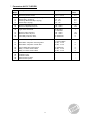
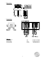
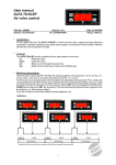
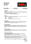
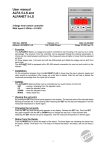
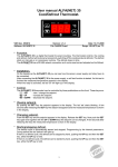
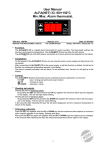
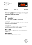
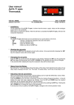
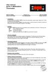
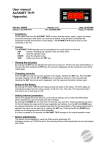
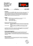
User manual ALFA 72-SP/DR -50/+150C Spraying/Drying Thermostat. VDH doc. 080652 Software: ALFA 72-SP/DR -50..150 Version: v2.0 Date: 24-02-2009 File: Do080652.wpd Range: -50/+150C * Installation. On the upper side from the ALFA 72-SP/DR is shown how the sensor, supply and relays should be connected. After power up a self test is started. If the self test is completed the measured temperature will be shown on the display. Thermostat-1 with function spraying is made by the sensor, set point-1 (spraying) and relay-1. Thermostat-2 with function drying is made by the sensor, set point-2 (drying) and relay-2. Relay-3 is an alarm relay. * Control. The ALFA 72-SP/DR thermostat can be controlled by four push buttons on the front: SET - viewing / changing the adjusted value and reset alarm. UP - raise the adjusted value. DOWN - lower the adjusted value. C - hidden key above the SET key. * Viewing the set points. Viewing set point thermostat-1 (spraying): By pushing the SET key simultaneously with the UP key, the adjusted set point from thermostat-1 (spraying) can be read out. Viewing set point thermostat-2 (drying): By pushing the SET key simultaneously with the DOWN key, the adjusted set point from thermostat-2 (drying) can be read out. A few seconds after releasing the SET key, the set point disappears and the measured value will be visible again. * Changing the set points. Push the SET key and the UP or DOWN key so the set point from thermostat 1 or 2 appears on the display. Release the SET key. By pushing the SET key again, the set point can be changed with the UP or DOWN keys. A few seconds after releasing the keys, the set point disappears and the measured value will be visible again. * Status from the Relais. Push the hidden C key. The three digits are indicating the status from the relays, hereby 0=off and 1=on. The code 110 means that relay 1 and relay 2 are on and relay 3 is off. Where OUT.1 is relay spraying, OUT.2 is relay drying and ALARM is relay alarm. 1 * Adjusting the interne parameters. Besides the adjusting of the set point there are a few internal adjustments possible. By pushing the DOWN key for more than 10 seconds the 'interne programming menu' will be entered. The upper and lower segment from the most left digit starts flashing. Now the required parameter can be selected with the UP and DOWN keys (see the table for the parameters). When the required parameter has been selected, it can be read out by pushing the SET key. It can be changed with the UP en DOWN keys. If no key is pushed for 20 seconds, the ALFA 72 SP/DR will return to it’s normal operating mode. * Adjusting the sensor. The sensor can be adjusted with the sensor offset parameter 05. Indicates the ALFA 72-SP/DR f.i. 2C to much, than the sensor offset should be lowered with 2C. * Error codes. On the display of the ALFANET 75 the following error messages can appear: LO - Minimum alarm Solution E1: HI - Maximum alarm - Check if sensor is connected correctly. E1 - Ssensor failure - Check sensor (1000/25C). EEE - Settings are lost. Solution EEE: - Reprogram the settings. -L- In case of sensor short-circuit the display alternates between error-code E.. and -L-, as indication for a short-circuit sensor. -H- - In case of open-circuit sensor the display alternates between error-code E.. and -H-, as indication for a open circuit sensor. Reset Alarm. When a error-messages appears it can be reset by pushing the SET key. The function of this key depends on parameter P42. * Technical details ALFA 72-SP/DR. Type Range Supply Read out Relays Control Front Sensor Dimensions Panel cut out Accuracy : ALFA 72-SP/DR Spraying/Drying Thermostat : -50/+150C, read out per 1C : 12Vac / 3VA, 50/60Hz, -5/+10% (or else see product sticker) : 3-digit 7-segments display : Ry1 spraying = SPST(NO)250V/8A (cos =1) of 250V/5A (cos =0.4) Ry2 drying = SPST(NO)250V/8A (cos =1) of 250V/5A (cos =0.4) Ry3 alarm = SPDT(NO/NC)250V/8A (cos =1) of 250V/5A (cos =0.4) Relays have one common (C). : Through push buttons on the front. : Polycarbonate IP65 : SM 811/2m (PTC 1000/25C). : 35 x 77 x 71,5mm (hwd) : 28 x 70mm (hw) : ± 0,5% from the range. - Provided with memory protection during power failure. - Equipped with self-test function and sensor-failure detection. - Connection with screw-terminals. - Special version on request available. 2 * Parameters ALFA 72-SP/DR ParaMeter description Parameter Range Default value 05 Offset temperature sensor -15.0..+15.0C 0.0 10 11 12 13 Switching differential relay 1 (spraying) Offset relay 1 (spraying) Switching differential relay 2 (drying) Offset relay 2 (drying) 0.1..15.0 -15..+15 0.1..15.0 -15..+15 0.5 0.0 0.5 0.0 25 26 Minimum adjustable set point Maximum adjustable set point -50..+150C -50..+150C 30 Type Alarm thermostat 31 32 33 34 Minimum alarm set point Maximum alarm set point Time delay minimum alarm Time delay maximum alarm 0= No alarm 1= Absolute -50..+150C -50..+150C 0..99 Minutes 0..99 Minutes 40 Function alarm relay 41 42 -50 +150 1 -50 +150 0 0 0 Reset alarm relay after recovering alarm Reset alarm relay after manual reset 0= Fail safe alarm 1= Control alarm 0= No, 1= Yes 0= No, 1= Yes 45 46 47 Control delay after power failure Relay-1 on when sensor failure Relay-2 on when sensor failure 0..99 Minutes 0= No, 1= Yes 0= No, 1= Yes 0 0 0 95 96 97 98 99 Software version Production year Production week Serial number (x1000) Serial number (units) - - 3 0 0 * Dimensions. * Connections. * Address. VDH Products BV Produktieweg 1 9301 ZS Roden The Netherlands Tel. Fax. Email: Internet: 4 +31 (0)50 - 30 28 900 +31 (0)50 - 30 28 980 [email protected] www.vdhproducts.nl