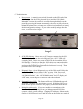
1
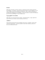
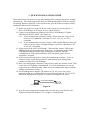
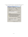
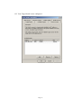
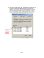
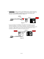
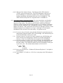
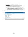
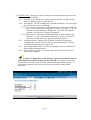
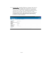
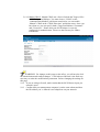
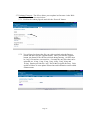
iS520, iS521 and iS550
User’s Manual
Version: 1.3
Page 1
LIMITED WARRANTY
Paralan Corporation (Paralan) warrants this product (Product) to be free of defects in material and
workmanship for an initial period of two (2) years from date of delivery to the original purchaser
(Purchaser) from Paralan.
Repair or Replacement. Paralan’s obligation under this warranty is limited to replacing or
repairing, at its option and at its facilities, any of the Products (except expendable parts thereof) what
within the warranty period are returned to Paralan and that are found by Paralan to be defective in proper
usage. Repair parts and replacement Products will be either new or reconditioned, at Paralan’s sole
discretion and furnished on an exchange basis with any replaced parts or Products becoming the property of
Paralan. In the event that Paralan determines, in its sole discretion, that the returned Product is not
defective, Purchaser shall pay a testing and handling free of seventy-five US Dollars ($75.00) per unit
tested. Products returned must be delivered to Paralan’s facility, or to an authorized Paralan service
representative, with all included parts and accessories as originally shipped, along with proof of purchase
and a Return Merchandise Authorization (RMA) number. The RMA number is obtained, in advance of
shipment, from Paralan’s Customer Service Department and is valid for thirty (30) days. Purchaser will be
responsible and liable for any missing or damaged parts.
Non-Paralan Products or Parts. Paralan is not liable for any defects in material or workmanship
of any products or parts which Paralan does not design or manufacture, including but not limited to power
supplies and cables. However, Paralan will honor the original manufacturer’s warranty for these products
or parts. In the event that Paralan determines that any defect is not related to a Paralan manufactured
Product, at Purchaser’s request, Paralan shall repair or replace the defective parts at Purchaser’s cost and
deliver the defective parts to Purchaser.
Abuse or Misuse. This limited warranty shall not apply if the Product has been misused,
carelessly handled, defaced, modified or altered, or if unauthorized repairs have been attempted by others.
Any such damage shall not be considered a defect.
Costs of Shipping. In order to obtain warranty service, the Product must be delivered to Paralan’s
facility, or to an authorized Paralan service representative. The RMA number must be clearly marked on
the exterior of the original shipping container or equivalent. Purchaser agrees to pre-pay shipping charges
one way, and to either insure the Product or assume the liability for loss or damage during transit. In the
event that Paralan determines that a Paralan Product is defective, Paralan will pre-pay transportation
charges back to Purchaser.
Limitation of Implied Warranties. THE FOREGOING WARRANTIES ARE IN LIEU OF ALL
WARRANTIES, EITHER EXPRESSED OR IMPLIED, INCLUDING WITHOUT LIMIATION ANY
IMPLIED WARRANTY OF MERCHANTABILITY OR FITNESS FOR A PARTICULAR PURPOSE,
AND OF ANY OTHER OBLIGATION ON THE PART OF PARALAN.
LIMITATION OF LIABILITY. PARALAN SHALL NOT BE LIABLE TO PURCHASER, TO
ITS CUSTOMERS OR TO ANY OTHER PERSON FOR ANY INJURY OR DAMAGE TO PERSONS
OR PROPERTY, OR FOR ANY LOSS OF OR INJURY TO BUSINESS, EARNINGS, PROFITS OR
GOODWILL SUFFERED BY ANY PERSON, INCLUDING PURCHASER AND CUSTOMERS,
CAUSED DIRECTLY OR INDIRECTLY BY THE PRODUCTS SOLD PURSUANT TO THIS
AGREEMENT; AND IN NO EVENT SHALL PARALAN BE LIABLE FOR ANY INDIRECT,
INCIDENTAL OR CONSEQUENTIAL DAMAGES SUFFERED BY PURCHASER, ITS CUSTOMERS
OR ANY OTHER PARTY, WHETHER SUCH LIABILITY ARISES FROMA CLAIM BASED ON
CONTRACT, WARRANTY, TORT OR OTHERWISE, EVEN IF PARALAN SHALL HAVE BEEN
ADVISED OF THE POSSIBILITY OF THE SAME. ANY PROVISION HEREIN TO THE CONTRARY
NOTWITHSTANDING, IN NO EVENT SHALL PARALAN’S LIABILITY EXCEED THE ACTUAL
AMOUNT PAID BY PURCHASER TO PARALAN FOR SUCH PRODUCTS.
Ship to: Paralan Corp. 4655 Ruffner Street San Diego, CA 92111
Page 2
NOTE: This equipment has been tested and found to comply within the limits for
a Class B digital device, pursuant to Part 15 of the FCC Rules. These limits are designed
to provide reasonable protection against harmful interference when the equipment is
operated in a commercial environment. This equipment generates, uses, and can radiate
radio frequency energy and, if not installed and used in accordance with the instruction
manual, may cause harmful interference to radio communications.
For continued compliance, this equipment must be used with high quality shielded
interface cables for external devices. The customers are responsible for ensuring
compliance with their enclosure.
Page 3
PARALAN CORPORATION
4655 Ruffner Street
San Diego, CA 92111
Toll Free: (866) 447-6293
Corporate: (858) 560-7266
Fax:
(858) 560-8929
E-Mail: [email protected]
Copyright 2005 Paralan Corporation
All Rights Reserved
PRINTED IN THE UNITED STATES OF AMERICA
NOTICE: The information in this documentation is subject to change without notice.
PARALAN CORPORATION MAKES NO WARRANTY OF ANY KIND
WITH REGARD TO THIS MATERIAL, INCLUDING, BUT NOT LIMITED TO,
THE IMPLIED WARRANTIES OF MERCHANTABILITY AND FITNESS FOR
A PARTICULAR PURPOSE. Paralan Corporation shall not be liable for errors
contained herein or for incidental or consequential damages in connection with the
furnishing, performance or use of this material.
This document contains proprietary information, which is protected by copyright.
All rights are reserved. No part of this document may be photocopied, reproduced or
translated to another language without the prior written consent of Paralan Corporation.
TRADEMARK ACKNOWLEDGEMENT
Paralan, Paralan Logo are trademarks or registered trademarks of Paralan Corporation.
Microsoft and Windows are registered trademarks of Microsoft Corporation. All other
brand and product names may be trademarks of their respective companies.
Page 4
Preface
This book is the primary reference and user’s manual for the iS5xx family of SCSI to
iSCSI Bridges. It contains a complete functional description of the iSCSI Bridge as well
as the complete physical and electrical specifications. It also contains instructions for
installing and configuring the iSCSI Bridge. Directions on how to connect SCSI/Ethernet
devices to the iSCSI Bridge are also included herein.
Typographic Conventions
When italic text is placed between less than (<) and greater than (>) signs, replace the
signs and italic text with the item described by the italic text.
Audience
This document will benefit persons installing and using any of Paralan’s iS520, iS521
and iS550 iSCSI Bridges. It assumes that the user has some familiarity with SCSI
devices and Ethernet networks.
Page 5
Revision History
VERSION
DATE
PAGE NO.
COMMENT
1.1
2/6/06
7
Change Appendices F
to E in Table of
Contents
1.2
2/16/06
35, 36,42
Add description of
power requirements
for iS520 & iS521.
Change EMI/RFI
Certification to Class
A. Add how to order
replacement power
supply for iS520.
1.3
2/21/06
All
Upgrade all screen
shots. Added CHAP
and multiple
connections. Changed
upgrade description.
Page 6
TABLE OF CONTENTS
1. QUICK INSTALLATION GUIDE……………………………………... 8-18
2. DESCRIPTION…………………………………………………………….. 19
3. FEATURES………………………………………………………………….19
4. INSTALLATION INSTRUCTIONS……………………………...……….20
4.1 Installation General………………………………………………….…... 20
4.2 SCSI Port General……….………………………………………………. 20
4.3 SCSI Topology……………………………………………………..…….21
4.4 SCSI Cables……………………………………………………………... 22
4.5 Connecting SCSI Devices………………………………………….……. 23
4.6 Ethernet Port General……………………………………………………. 23
4.7 Ethernet Cables………………………………………………………….. 24
4.8 Connecting to the Ethernet Network……………………………………..24
4.9 Power On Sequence……………………………………………………... 24
4.10 LEDs……………………………………………………………….……25
4.11 Accessing Paralan’s Web-based Utility………………………………... 26
5. CONFIGURING THROUGH WEB-BASED UTILITY…………………28
5.1 General…………………………………………………………………... 28
5.2 Admin Page……………………………………………………………… 28
5.3 Diagnostic Page…………………………………………………………. 29
5.4 Web Port Page……………………………………………………….…...30
5.5 SCSI Bus Page……………………………………………………….….. 31
5.6 iSCSI Target Page…………………………………………………..…… 32
5.7 Updating Firmware……………………………………………………… 35
6. APPENDICES……………………………………………………….……... 37
A. Specifications…………………………….…………………….………... 37
B. Glossary………………………………………………..………………… 40
C. Troubleshooting……………………………………………………..……43
D. Factory Defaults……………………………………………………….… 44
E. Technical Assistance………………………………….……………….….45
Page 7
1. QUICK INSTALLATION GUIDE
These instructions will get the user up and running quickly using the most basic settings
and topology. This setup assumes that both your management and iSCSI host computer
are running Windows 2000/XP. It also assumes that your iSCSI Host computer will be
running the Microsoft iSCSI initiator.
1.1 Make sure all devices on the SCSI side of the system are powered down, i.e.
iS5xx iSCSI Bridge, SCSI target devices, and SCSI hosts.
1.2 Connect your management computer to the iS5xx iSCSI Bridge’s Gigabit
Ethernet port labeled “iSCSI” (See Figure A).
1.2.1 If your management computer is using a 10/100 Network card you will
need to use a “crossover” cable that is CAT 5, CAT 5e, or CAT 6
compliant.
1.2.2 If your management computer is using a GbE (Gigabit Ethernet) Network
card you can use either a straight-through or crossover cable that is CAT
5e or CAT 6 compliant.
1.3 Apply power to the iS5xx iSCSI Bridge. Wait until the “Status” LED (Light
Emitting Diode) on the bridge turns solid green. A solid green on the Status
LED indicates that the unit has fully booted and is ready for Ethernet
communication. If the Status LED does NOT turn green, please refer to
Appendix C section d.
1.4 If you have not already done so, boot your management computer. If you are
using a firewall, ensure that port 4443 is open between your management
computer and the iS5xx iSCSI Bridge.
1.5 Once your management computer is fully booted, make sure that the “Link” LED
on the iS5xx iSCSI Bridge is illuminated. If it is not illuminated, you may be
using an incorrect Ethernet cable. Make sure your configuration agrees with the
cabling requirements of step 1.2.
1.6 Set the management computer’s IP address to 192.168.1.xxx (xxx can be
substituted with any available address except 200) and subnet to 255.255.255.0.
Reboot the management computer, if needed, for settings to take effect.
10/100 /1000 ET HERN ET
iS 5x x iS CS I BR IDGE
MAN AGEM EN T C OMP UTE R
Figure A
1.7 Now that your management computer has rebooted, open your Web browser.
Windows IE (Internet Explorer) 5.5 or higher is recommended.
Page 8
1.8 Type in https://192.168.1.200:4443/enter.php as the URL (see Glossary) and
press enter. The following Login page should appear:
1.9 Enter the default Username and Password and click on the Login tab.
1.9.1 Username: admin
1.9.2 Password: password
Page 9
1.10 You should now be at the Home page. Click on the “iSCSI Target” tab.
1.11 Now you can start configuring your unit for your final iSCSI topology (See
section 1.16 Figure B). Modify the iSCSI Target Port settings accordingly.
Ensure that the iSCSI Host computer and the iS5xx iSCSI Bridge are on the
same subnet.
This subnet must match the iSCSI Host
machine wishing to access the SCSI devices
connected to the iS5xx iSCSI Bridge.
The correct Gateway number must be
entered if using a Gateway to reach the iS5xx.
Otherwise, leave blank.
Page 10
1.12 Confirm changes.
1.13 Once you’ve confirmed changes, the iSCSI Target page will renew with your
updated settings.
Page 11
1.14 In order for your settings to take affect, you will need to reboot the unit. Click
on the Diagnostics tab. On the Diagnostics page, click on “Reboot Device”.
The unit will begin reboot after 5 seconds. Wait until the “Status” LED on the
Bridge turns solid green.
1.15 Once the iS5xx iSCSI Bridge has rebooted and the “Status” LED is solid green
you have successfully configured your iS5xx iSCSI Bridge. If the SCSI bus
settings (see section 5.5) or the Web Port interface access (see section 5.4) is to
be changed, you will need to re-login. See steps 1.8 and 1.9 for instructions on
how to log in.
1.16 It is now time to connect all devices for your final setup. Make sure
all devices on the SCSI side of the system are powered down, i.e. iS5xx iSCSI
Bridge, SCSI drives, and SCSI hosts.
10/100/1000 ETHERNET
SCSI BUS
Termination
iS5xx iSCSI B RI DG E
iSCSI HO ST COMPUTER
S CS I
TAPE
Figure B
Page 12
SCSI RAID
1.17 Connect the SCSI devices to the iS5xx iSCSI Bridge.
1.17.1 Connect the cable from the SCSI devices to the 68-pin SCSI port on the
iS5xx iSCSI Bridge.
1.17.2 Make sure the IDs of the SCSI devices connected to the iS5xx iSCSI
Bridge are set to a values other than 7.
1.17.3 Terminate the SCSI bus at the last physical SCSI device. The iS5xx iSCSI
Bridge is terminated internally by default.
1.18 Connect the iS5xx iSCSI Bridge’s Ethernet port to your iSCSI Host computer
via a CAT 5e or CAT 6 cable. If your management computer is functioning as
your iSCSI Host computer, this step can be skipped.
1.19 Turn on your SCSI targets and wait for them to be ready.
1.20 Apply power to the iS5xx iSCSI Bridge.
1.21 Wait until the Status LED on the bridge turns solid green. The iS5xx iSCSI
Bridge will automatically discover all SCSI targets on the bus. If there are no
SCSI targets connected, the “SCSI” LED will constantly pulse. In this case,
see the Troubleshooting section C.b in the Appendices.
Page 13
1.22 Power on your iSCSI Host computer. Open the Microsoft Initiator. Click on the
“Initiator Settings” tab. Modify your “initiator node name” accordingly.
Page 14
1.23 Click on the “Target Portals” tab. Add an available portal.
Page 15
1.24 Enter an Address that matches the “IP Address” you entered in step 1.11. Enter
the Socket port that matches the “iSCSI Protocol Port” you entered in step 1.11
Click “OK”.
Page 16
1.25 Your Target Portal is now configured.
Page 17
1.26 Click on the “Available Targets” tab. Click on Refresh. After the screen has
refreshed, all available targets through the iS5xx iSCSI Bridge will be
displayed. You will need to “Log On” to each one before your iSCSI Host
computer is able to fully communicate with the SCSI targets. If a target
drive is to be permanently located, use the “Persistent Targets” tab to set its
location so that it will be automatically available upon system boot-up.
Each “Name”
represents an
actual SCSI drive
connected to a
single iS5xx
iSCSI Bridge.
Page 18
2. DESCRIPTION
2.1 General. Congratulations on your purchase of Paralan’s iS5xx series iSCSI
Bridge! Paralan’s family of iSCSI Bridges make it possible to merge parallel
SCSI storage into IP (iSCSI) Storage Area Networks (SANs). If you do not
have an IP SAN, Paralan’s iSCSI Bridges will easily and inexpensively locate
storage and backup SCSI devices anywhere for disaster recovery or remote
backup – yards, meters, kilometers, or miles – the distance is unlimited! Paralan
offers the iSCSI Bridge in three standard form factors to meet a variety of
configuration needs:
2.1.1 iS520: Stand-Alone Box version. Simply connect cables and
apply power.
2.1.2 iS521: Board version. Perfect for OEMs and System Integrators
to incorporate into their own packages.
2.1.3 iS550: Rack Mountable version. Conveniently mounts Paralan’s
iSCSI Bridges into storage racks.
3. FEATURES
3.1 Feature Overview.
3.1.1 Both targets and initiators may be located on the SCSI side of the Bridge.
3.1.2 Communicates with SCSI disk, tape drives and libraries, RAID
controllers, DVD, MO and CD jukeboxes.
3.1.3 Allows full SCSI cable lengths on the SCSI side of the Bridge.
3.1.4 SCSI LVD operation up to 160 MBYTES/SEC using 68 pin high-density
“P” connector and conforms to the full ANSI standard.
3.1.5 The iSCSI Bridge is backward compatible with all older versions LVD
and SE SCSI.
3.1.6 Mode switching of LVD or SE is done on the fly by monitoring the
DIFFSENS signal and automatically supports all Single-Ended SCSI
versions.
3.1.7 SCSI ID for iSCSI Bridge is configurable.
3.1.8 User can optionally supply power for terminators on the SCSI bus (up to 1
Amp).
3.1.9 Unit can force Single-Ended operation on SCSI bus.
3.1.10 User can optionally use on-board terminators.
3.1.11 Supports 1.0 Gb/s Ethernet link speed – Full duplex.
3.1.12 Ethernet interconnect operates up to 100 meters (328 feet) of 1000Base-T
Copper (CAT-5e or CAT-6) cabling using a single RJ45 connector.
Switches and routers may be used to extend the distances.
3.1.13 Configurable IP port for “system” management, upgrades and diagnostics.
Downloads achievable via on-board Web-based Utility using the most
common industry web browsers, e.g. Microsoft’s Internet Explorer.
3.1.14 64bit/66MHz internal PCI bus architecture.
3.1.15 16MB of Flash ROM.
Page 19
3.1.16 256MB SDRAM.
3.1.17 833MHz Freescale processor.
3.1.18 Capable of assigning a unique iSCSI name to each device on the SCSI side
of the bus.
3.1.19 Can automatically obtain an IP address from a DHCP server or the user
can manually assign an IP address, Subnet mask and Gateway to the iSCSI
Protocol Port and Web Port.
3.1.20 Diagnostic web page monitors unit’s boot status.
3.1.21 Diagnostic LEDs for quick and easy unit status.
3.1.22 Modifying the “User Name” and “Password” can customize user login
access.
3.1.23 Hardware override configuration for systems that require a more secure
setup.
3.1.24 Unit can easily be reset to factory default configuration.
3.1.25 Up to 100MB/sec throughput.
3.1.26 The iS520 (Stand-Alone Box version) provides a lockable 5-pin DIN
power connector for added reliability.
3.1.27 Supports One-way and Mutual CHAP security.
3.1.28 Ambient Temperature Shutdown protection.
4. INSTALLATION INSTRUCTIONS
4.1 Installation General. Before you begin installation, make sure all devices on the
SCSI side of the system are powered down, i.e. iS5xx iSCSI Bridge and SCSI
devices (hosts and targets).
4.2 SCSI Port General. The iS5xx series iSCSI Bridges provide a single SCSI port
for connecting your SCSI devices to your iSCSI network. The SCSI port consists
of a 68-pin High Density “P” SCSI bus connector (see Image 1). Disks, tape
drives, RAID controllers, DVD, MO and CD libraries are supported. Low
Voltage Differential (LVD) transmission mode, Single-Ended (SE) transmission
mode and transfer rates of up to 160 MBYTES/SEC are supported.
Image 1
Page 20
4.3 SCSI Topology. Paralan’s family of iSCSI Bridges may be connected anywhere
on the SCSI bus. All models are supplied with on-board terminators enabled. In
most cases the iSCSI Bridge will be placed at the end of the SCSI bus and
terminators should NOT be disabled (see Figure C).
On-Board
Terminator
SCSI BUS
Termination
T
10/100/1000 ETHERNET
iS5 xx iSCSI BRIDGE
iSCSI HOST CO MPUTER
SCSI
TAPE
Figure C
S CS I RAI D
If you are placing the iSCSI Bridge in the middle of the SCSI bus, you must
disable the terminators on the iS5xx (see Figure D). To disable terminators,
access the SCSI Bus page on the Web-based Utility and turn the terminators to the
off position. Make sure the devices at the ends of the SCSI bus have correct
termination and that the terminators are properly powered.
SCSI BUS
Termination
Termination
iS 5xx
iS CS I
BRIDG E
SCSI
TAPE
10/100/1000 ETHERNET
iSCSI HO ST COMPUTER
Figure D
Page 21
SCSI RAID
4.4 SCSI Cables. The most important ingredient in the successful installation of any
SCSI system is proper cabling. Many round SCSI cables are, at best, marginal on
single-ended systems and will not work at all on differential SCSI systems.
Many other round SCSI cables are assembled in a manner that has no regard for
wire pair selection. These cables appear to work most of the time but may cause
intermittent problems on the SCSI bus that are extremely difficult to
troubleshoot. Also, the longer the SCSI cables, and faster the maximum bus
speed, the more important a factor the cables become. Because of these “cable
factors”, should you have problems getting your system to work properly with
Paralan iS5xx series Bridges, we suggest temporarily replacing your round SCSI
cables with flat twisted pair ribbon cables as they are normally SCSI correct.
Also, contact Paralan for our “SCSI Quiet Cable” data sheet. Note, the maximum
number of devices allowed on the SCSI bus and the maximum bus cable length
are determined by the bus speed and bus width of the system (see Table 1 below).
Table 1
STA Terms
SCSI-1 (narrow)
Fast SCSI (narrow)
Fast Wide SCSI
ANSI Terms
FAST-5
FAST-10
FAST-10
Ultra SCSI (narrow) FAST-20
Bus Speed,
MBytes/Sec.
Max.
5
10
20
Bus
Width,
bits
8
8
16
20
8
Max. Bus Lengths, Meters
Single- ended
LVD
HVD
6
25
25
3
25
25
3
25
25
1.5
25
25
3
25
25
FAST-20
40
16
N/A
1.5
3
Ultra2 SCSI (narrow) FAST-40
40
8
N/A
25
M
12
N/A
N/A
8
P
Wide Ultra2 SCSI
FAST-40
80
16
N/A
25
M
12
N/A
N/A
16
Ultra3 SCSI or
Ultra160 SCSI
FAST-80
160
16
N/A
25
M
12
N/A
16
Ultra320 SCSI
FAST-160
320
16
N/A
25
M
12
N/A
16
Wide Ultra SCSI
25
25
25
Max.*
Device
Support
8
8
16
8
4
P
25
25
25
16
8
4
P
P
P = Point-to-point interconnect. Only 1 SCSI Initiator and 1 Target on the bus.
M = Multidrop interconnect. At least 1 SCSI Initiator and 2 Targets on the bus.
* = Includes all SCSI Targets and Initiators.
Page 22
4.5 Connecting SCSI Devices. SCSI cable installation is easy. This installation
assumes the topology in Figure C of section 4.3.
4.5.1 Simply connect a SCSI cable into Paralan’s iSCSI Bridge’s 68-pin High
Density “P” SCSI bus Connector (see Image 1 of section 4.2).
4.5.2 Connect the other end of your cable to your SCSI device(s).
4.5.3 Make sure to abide by the SCSI cable length limitations recommended in
Table 1 of section 4.4.
4.5.4 Set the IDs of the SCSI devices connected to the iSCSI Bridge to a value
other than 7. Each device should have a unique ID. The iSCSI Bridge is
set to ID 7 by default. To change the default ID, refer to section 5.5.
4.5.5 Make sure that the last device on the bus, e.g. the SCSI RAID device in
Figure C, is terminated.
4.5.6 For the more advanced configuration in Figure D please contact Paralan
for assistance.
4.6 Ethernet Port General. An RJ45 Connector (labeled “iSCSI”, see Image 2) is
used to connect the iSCSI Bridge to your iSCSI SAN or management computer.
The port is 10/100/1000 Mb/sec, full duplex capable. The Ethernet port
automatically negotiates the appropriate link speed with the connected devices.
A minimum of CAT-5E cable is necessary for the unit to operate at full speed,
i.e. 1000Mb/sec.
Image 2
Page 23
4.7 Ethernet Cables. You must choose your Ethernet cable carefully depending upon
your configuration. If you are connecting your iSCSI Bridge directly to a
management computer, a crossover cable is necessary. If you are connecting
through an Ethernet switch or router, a straight-through cable will suffice. The
type of cable used is equally important (see Table 2 below). Note that if you are
connecting the iSCSI Bridge to an Ethernet device that is 1000 Mb/s capable, you
can use either a crossover or straight through wire cable.
Table 2
Topology
Bridge Management Computer
Bridge Switch or Router
Cable Type
Max
Cable Length
(in meters)
Cable Wiring
CAT-5 or higher
CAT-5E/CAT-6
CAT-5 or higher
CAT-5E/CAT-6
100m (min)
100m
100m (min)
100m
Crossover
Straight/Crossover
Straight
Straight/Crossover
Management
Computer/Switch
/Router
Connection Speed
10/100 Mb/s
10/100/1000 Mb/s
10/100 Mb/s
10/100/1000 Mb/s
4.8 Connecting to the Ethernet Network. Simply connect your iSCSI Bridge to your
management computer, switch, router or gateway. For further Ethernet
configuration instruction, refer to section 4.11.
4.9 Power On Sequence. Now that you have connected all components of your
iSCSI to SCSI system, it is time to power up the devices.
PLEASE FOLLOW THE POWER UP SEQUENCE BELOW!:
4.9.1 Turn on your SCSI targets and wait for them to be ready.
4.9.2 Apply power to the iS5xx iSCSI Bridge. The iS520 (Stand-Alone Box
Version) unit comes with a power adapter with a lockable connecter to the
iS5xx iSCSI Bridge.
4.9.3 Wait until the Status LED on the bridge turns solid green. The iS5xx
iSCSI Bridge will automatically discover all SCSI targets on the bus. If
there are no SCSI targets connected, the “SCSI” LED will constantly
pulse. In this case, make sure the targets are powered on, the SCSI cables
are connected and the termination is properly placed.
4.9.4 Your SCSI targets are now accessible to your iSCSI network!!!
4.9.5 You may now configure your iSCSI system through its Web-based Utility
using a web browser (see section 4.11).
Page 24
4.10 LEDs. There are 5 LEDs on the iSCSI Bridge that can be used for
status/diagnostics (see Image 2 of section 4.6)
4.10.1 SCSI Activity (Yellow). The SCSI Activity LED is labeled “SCSI” on
the iS520 and iS550. During normal operation, this LED turns on
when there is SCSI activity on the SCSI bus. However, the LED will
also indicate when there are no SCSI targets on the SCSI bus. After
initial boot, i.e. after the Status LED has turned solid green, if the
SCSI Activity LED is continuously blinking at a constant half second
rate, the unit has found no targets on the SCSI bus.
4.10.2 Status (Red/Green). The Status LED is labeled
“STAT” on the iS520 and iS550. The Status LED identifies what
stage the boot process is in. It also notifies the user when an update is
being loaded into the unit by turning solid red. Once
the update is complete, the LED will return to a solid green state.
Please refer to table 3 below.
Description
Boot Loader
Operating System
Network Interface
Web-based Utility
SCSI
iSCSI
Boot Complete
Updating Unit
Color
OFF
N/A
RED
RED
RED
RED
GREEN
RED
State
OFF
SOLID
5 BLINKS
3 BLINKS
2 BLINKS
4 BLINKS
SOLID
SOLID (During Burning)
Table 3
4.10.3 Power (Red/Green). The Power LED is labeled
“PWR” on the iS520 and iS550. This LED will turn solid green when
there is sufficient power to the unit. The LED will turn off when the
unit is NOT powered. The LED will turn solid RED when the
immediate ambient temperature has exceeded 65°C. The unit will be
held in reset and the user will not be able to communicate with it once
in this state. If the user wishes to restart the unit first bring the
ambient temperature down to an acceptable level (<40°C), wait 10
minutes and press the reset button.
4.10.4 Ethernet Data (Green). The Ethernet Data LED is labeled
“DATA” on the iS520 and iS550. This LED turns on when there is
activity to/from the iSCSI Bridge on the Ethernet network.
Page 25
4.10.5 Ethernet Link (Yellow/Green). The Ethernet Link LED is labeled
“LINK” on the iS520 and iS550. This LED illuminates solid green if
the iSCSI Bridge is connected to another active Ethernet component
and has negotiated a data transmission rate of 10 or 100Mb/sec. The
LED will turn solid yellow for a negotiated rate of 1000Mb/sec.
4.11 Accessing Paralan’s Web-based Utility. For your convenience, use Paralan’s
iSCSI Bridge’s Web-based Utility for configuration. Section 5 explains all
functions of this utility. The utility can be accessed via Microsoft Internet
Explorer or other common browsers through the use of a computer (commonly
referred to in this document as the “management computer”) connected to the
Bridge via Ethernet. This connection may be direct or through a network. If the
Bridge has never been configured, use steps 1.4 through 1.10 in the Quick
Installation Guide section to access the utility. For general access:
4.11.1 If you are using a firewall, ensure that the Web port is open between your
management computer and the iS5xx iSCSI Bridge. The default Web port
for the iSCSI Bridge’s Web port is 4443.
5.1.1 Note the Gateway you have previously assigned your iSCSI Bridge and
make sure that your management computer is accessible through this
Gateway. There is no default Gateway assigned to the iSCSI Bridge.
4.11.2 Note the IP Address you have previously assigned your iSCSI Bridge and
make sure that your management computer and the iSCSI Bridge are on
the same subnet. The default IP Address for the iSCSI Bridge’s Web port
is 192.168.1.200. The default Subnet Mask is 255.255.255.0.
Subnet iS5xx
Location
4.11.3 Open your Web browser. Windows IE (Internet Explorer) 5.5 or higher is
recommended.
4.11.4 Type in https://<IP Address>:<Web Port>/enter.php as the URL and press
enter.
Page 26
4.11.5 The Login page below should appear. Enter your Username and Password
and click on the Login tab. The default Username is “admin” and the
default Password is “password”.
4.11.6 You should now be at the Home page. You are now ready to configure
your iSCSI Bridge (see section 5).
Page 27
5. CONFIGURING THROUGH WEB-BASED UTILITY
5.1 General. Paralan’s iSCSI Bridge Web-based Utility configures the unit for many
different environments and applications; monitors boot status and updates
firmware. Please note that your unit’s serial number is depicted at the upper right
hand corner of each web page of the utility.
5.1.2 UNIT MUST BE FULLY BOOTED BEFORE CHANGES TO THE
WEB-BASED UTILITY CAN BE MADE! The unit is considered fully
booted when the “Status” LED is solid green.
5.1.3 FOR ANY CHANGE TO TAKE EFFECT, THE UNIT MUST BE
REBOOTED!
5.2 Admin Page. The first thing you should do after you’ve accessed the Web-based
Utility, is click on the Admin page and change your User Name and Password.
This will give your system an added level of security. The Admin page also
allows you to change your hardware MAC address. Lastly, this page allows you
to update the firmware of the unit (please refer to the “Updating Firmware”
section 5.7).
WARNING! For changes to the User Name, Password and MAC address to
take affect, you will need to click the associated submit button and confirm
changes. A full reboot of the unit is the final step necessary to make the
modifications permanent.
Page 28
5.3 Diagnostic Page. The Diagnostics Page’s three purposes:
5.3.1 To ensure a clean boot of the iSCSI Bridge. If any part of the iSCSI
Bridge unit fails to initialize, it will be indicated on this page. In such an
event, refer to the Troubleshooting Appendix E of this book.
5.3.2 The current firmware your unit is running is also displayed on this page.
5.3.3 Finally, you can reset your unit by clicking on the “Reboot Device”
button. Once pressed, it will take 10 seconds before the unit reboots. You
will need to wait until the “Status” LED turns solid green before the Webbased Utility will be accessible (Please refer to section 4.11.4 to re-access
the Web-based Utility).
Page 29
5.4 Web Port Page. By using the Web Port page, the user can modify the “IP
Address”, “Subnet Mask”, “Gateway” and “Web Port” settings for the Web-based
Utility. By default, there are two network ports on the iSCSI Bridge connected to
the same physical RJ45 connector; the Web Port and the iSCSI Target Port. To
simplify access to the Bridge you can set the Web Port settings to mirror the
iSCSI Target Port settings. To enable this option, click the “Yes” radial button
associated with the “Use iSCSI Port Settings” label. Once enabled, you will only
be able to access the Web-based Utility via the iSCSI Target port settings.
WARNING! For changes to this page to take affect, you will need to click
the submit button and confirm changes. A full reboot of the unit is the final step
necessary to make the modifications permanent. Before changing the settings on
this page:
5.4.1 If you are using a firewall, make certain that the Web port you entered is
open.
5.4.2 Confirm that your management computer is on the same subnet and that
the IP Address you’ve entered is not a duplicate on your network.
Page 30
5.5 SCSI Bus Page. This page is used to configure certain parameters specific to the
SCSI bus interface. Namely:
5.5.1 SCSI ID: You must choose a unique value for this ID. No other device
on the SCSI bus can have a duplicate ID.
5.5.2 Termination: The iSCSI Bridge has on-board terminators. You can toggle
these terminators on/off via this page.
5.5.2.1 If you turn the terminators off and the Bridge is at the end of the SCSI
bus, i.e. your system has the topology of section 4.3 Figure C, you will
need an external terminator at Bridge end. Also make sure that the
opposite end of the bus is properly terminated.
5.5.2.2 If you turn the terminators off and the Bridge is in the middle of the
SCSI bus, i.e. your system has the topology of section 4.3 Figure D,
make sure that the ends of the bus are properly terminated.
5.5.3 Terminator Power: Paralan’s iSCSI Bridge is capable of supplying
enough power to the SCSI bus to turn on 1 set of terminators. The user
can optionally turn this power supply off.
5.5.4 Force Single Ended SCSI: The user can optionally force the SCSI bus to
Single-Ended communications.
5.5.5 Force Ultra SCSI: The user can optionally slow the SCSI bus down to
Ultra speeds (40MB/s).
WARNING! Regardless of the topology, a powered terminator must be
on the SCSI bus for the system to operate correctly! For changes to this page
to take affect, you will need to click the submit button and confirm changes. A
full reboot of the unit is the final step necessary to make the modifications
permanent.
Page 31
5.6 iSCSI Target Page. By using the iSCSI Target page, the user can modify the “IP
Address”, “Subnet Mask”, “Gateway”, “iSCSI Name Prefix”, “iSCSI Protocol
Port”, “Max Connections” and “Authentication Method” settings for the iSCSI
Target on the Bridge. By default, the iSCSI Bridge’s connection type is set to
Static, i.e. the IP Address and Subnet Mask are permanent, as shown in the screen
capture below. If you have a DHCP server on your network connected to the
iSCSI Bridge and wish for the Bridge to “Obtain IP Automatically”, simply click
“Yes” at the label. By default the “iSCSI Name Prefix” is “iqn:199510.com.paralan-<last 4 digits of serial number>:”. Note that “iSCSI Name
Prefix” is how the iSCSI Bridge will be seen by your iSCSI Initiator. For
example, if you have a SCSI target ID 3 connected to the iSCSI Bridge, your
iSCSI Initiator would identify this target during discovery as “iqn:199510.com.paralan-<last 4 digits of serial number>:3”. The “Max Connections” field
is used to specify multiple iSCSI Initiator connections to the iSCSI Bridge.
5.6.1
CHAP (Challenge-Handshake Authentication Protocol). The iS5xx Series
Bridges have the ability to set CHAP usernames and secrets. One-Way
(Targets must authenticate the Initiators) and Mutual CHAP (Targets and
Initiators must independently authenticate one another) are supported.
Once authentication has been made and communications are established,
normal operations between the two authenticating devices can happen,
thus the overall system overhead is not affected. The iS5xx iSCSI Series
Bridges are initially provided with CHAP turned off.
Page 32
5.6.1.1 One-Way CHAP. One-Way CHAP sets a “Username” and “Secret” in
the Target (iS5xx iSCSI Bridge) that an initiating device must use in
order for the Target to authenticate the Initiator for communications.
You must choose “CHAP” on the “Authentication Method” pull-down
menu before you can enable “One-Way” CHAP in the “CHAP
Direction” pull-down menu. Once you have done so, you can specify
a “Target Username” and a “Target Usersecret”. Ensure that your
iSCSI Intiator is correctly configured for authentication. Please see
the Glossary for further information.
Page 33
5.6.1.2 Mutual CHAP. Mutual CHAP sets a Secret for both the Target (iS5xx
iSCSI Bridge) and Initiator. You must choose “CHAP” on the
“Authentication Method” pull-down menu before you can enable
“Mutual” CHAP in the “CHAP Direction” pull-down menu. Once you
have done so, you can specify both a Target and Initiator “Username”
and “Usersecret”. Ensure that your iSCSI Intiator is correctly
configured for authentication. Please see the Glossary for further
information.
WARNING! For changes to this page to take affect, you will need to click
the submit button and confirm changes. A full reboot of the unit is the final step
necessary to make the modifications permanent. Before changing the settings on
this page:
5.6.2 If you are using a firewall, make certain that the iSCSI Protocol port you
entered is open.
5.6.3 Confirm that your management computer is on the same subnet and that
the IP Address you’ve entered is not a duplicate on your network.
Page 34
5.7 Updating Firmware. The iS5xx allows you to update its firmware via the Webbased Utility. Follow the steps below:
5.7.1 Click on the Admin page tab and click the “Proceed” button.
5.7.2 You will need to choose the file you wish to upload using the Browse
button and then click the Upgrade button. Once you click the Upgrade
button, the Status LED will turn solid red during burning. All files must
be “img” files and are case sensitive. Currently the only files that can be
uploaded are: 0.img, 1.img, 2.img, 3.img, 4.img, 5.img, 8.img and
10.img. Paralan provides the “img” files within a zipped directory. Each
update will have its own update instructions and information on the added
enhancements.
Page 35
5.7.3 Wait until the “Upgrade Complete” message appears and the Status LED
returns to a solid green state before continuing to the next file you wish to
update. If you wish to update an additional file, repeat steps 5.7.1 through
5.7.3.
5.7.4 Once all uploads are complete, reboot the unit via the Diagnostic page or
cycle power on the iSCSI Bridge to activate the new firmware!
Page 36
6. APPENDICES
A. Specifications
I.
Environmental:
a. Relative Humidity: 10-90% non-condensing
b. Operating Temperature: 5 - 40°C
c. Storage Temperature: 0 - 85°C
d. Airflow (for iS521 only): 10 cubic feet per minute
II.
Power Requirements:
a. iS520 (Stand-Alone Box version). The iS520 is a stand-alone unit in
an enclosure with a power supply designed to plug into the line voltage
outlet of 100-240 VAC, 50/60 Hz, 1.7 A. A replacement power supply
can be ordered as Paralan part number 10641-1.
• Input Voltage
100 - 240 VAC
• Input Current
1.7 A AC
• Input Frequency
50 - 60 Hz
b. iS550 (Rack Mountable version)
• Input Voltage
100 - 240 VAC
• Input Current
1.2 A AC
• Input Frequency
50 - 60 Hz
c. iS521 (Board version). The iS521 board level unit requires a source of
5 Vdc ± 5%, 100 mv max ripple, 5 Amps (max). This current is for
the board only. Installations using the iS521 will pull additional
current if required to power external terminators. Total typical current
draw for external terminators would be 350 mA. The iS521 is current
limited to 1.67 Amps to the external terminators.
• Voltage
5 Vdc ± 5%
100 millivolt max ripple
• Current
5 AMP DC (max)
• 4-pin Power Connector pin-out
Pin
Description
1
No connect
2
Ground
3
Ground
4 +5 Volt input
III.
Agency Approvals: UL, CSA, TUV/VDE, CE (Contact Paralan to request
documentation).
Page 37
IV.
EMI/RFI:
• Meets FCC Class A, CE
Note: The iS520 uses an external universal power supply (included)
that has all required agency approvals. The iS520, iS550 and iS521
use UL listed PC boards and UL compliant parts.
V.
Physical Dimensions:
a. iS520 (Stand-Alone Box version)
• Height: 1.6 in (41 mm)
• Width: 5.6 in (142 mm)
• Depth: 9.25 in (235 mm)
b. iS550 (Rack Mountable version)
• Height: 1.72 in (43.7 mm)
• Width: 16.75 in (425.5 mm)
• Depth: 10.0 in (254 mm)
• Vertical Rack Space 1U (1.75”, 44.5 mm)
c. IS520 Power Supply Adapter. A replacement power supply can be
ordered as Paralan part number 10641-1.
• Height: 1.56 in (39.50 mm)
• Width: 2.76 in (70.00 mm)
• Depth: 4.72 in (120.00 mm)
Page 38
d. iS521 (Board version). Dimensions are in inches.
Page 39
B. Glossary
CHAP – Challenge-Handshake Authentication Protocol. A form of authentication
between iSCSI Initiators and Targets. See One-Way CHAP and Mutual CHAP.
Crossover Cable – A network cable that crosses the transmit and receive lines.
Typically used to connect computers directly together, i.e. computers that are NOT
connected via a hub, switch or router.
Firewall – The primary method for keeping a computer secure from intruders. A
firewall allows or blocks traffic into and out of a private network or the user’s
computer. Firewall’s can be implemented via software or hardware, e.g. a router.
Gateway – A computer/router that acts as a go-between for two or more networks. In
this case, the gateway functions as an entry/exit point to the network.
IP Address – Internet Protocol Address. The address of a device attached to an IP
network (TCP/IP network). Every client, server and network device must have a
unique IP address for each network connection.
iSCSI – Internet SCSI. An Internet Protocol that serializes SCSI commands and
converts them to TCP/IP (Ethernet).
iSCSI Host Computer – Computer that contains your iSCSI Initiator.
iSCSI Target – For the purpose of this document, the iSCSI Target refers to your
iS5xx iSCSI Bridge.
LED – Light Emitting Diode. A semiconductor device that emits visible light when
an electric current passes through it.
LVD – Low Voltage Differential. Type of signal transmission used by SCSI. LVD
supports cable lengths of up to 25 meters.
MAC Address – Media Access Control Address. The unique serial number burned
into Ethernet devices (e.g. Paralan’s iS5xx iSCSI Bridge) that identifies each device
from all others.
Management Computer – Computer used to access the iS5xx iSCSI Bridge’s Webbased Utility for configuration.
Mutual CHAP – Username and Secret for both the Target (iS5xx iSCSI Bridge) and
the Initiator. When the Initiator contacts the iS5xx iSCSI Bridge, the Initiator must
provide the correct Secret, then if the password is correct, the iS5xx will provide the
Return Secret that the Initiator requires, which was set in the iS5xx when Mutual
CHAP was turned on in the Web Based Utility. In this way, both the Initiator and the
Page 40
Target are protected from unauthorized iSCSI access. Mutual CHAP provides an
added protection over One-Way CHAP for iSCSI communications on the Storage
Network. See CHAP and One-Way CHAP.
One-Way CHAP – Username and Secret in the Target (iS5xx iSCSI Bridge) that an
initiating device must use in order for the Target to authenticate the initiator for
communications. When the Initiator tries to contact the Target, the Target will
challenge the initiator to provide the correct Secret. If it is not provided, the Target
will not communicate with the Initiator. In this way, the Target device will not be
able to be accessed casually by other computers that do not have the One-Way CHAP
Secret, but can communicate on the same network. Both Microsoft’s iSCSI Initiator
software and the iS5xx iSCSI Bridges have the capability of setting both One-Way
and Mutual CHAP for secure system communications. See CHAP and Mutual CHAP.
SAN – Storage Area Network. A network of storage disks. In large enterprises, a
SAN connects multiple servers to a centralized pool of disk storage.
SCSI – The Small Computer System Interface standard for interfacing multiple
computers and devices. SCSI has three defined methods of parallel signal
communications, Low Voltage Differential (LVD), Single-Ended (SE) and High
Voltage Differential (HVD). Most LVD SCSI devices are Multimode, which allows
them to be backwards compatible with SE. The backwards compatibility is called
LVD/MSE.
SCSI Initiator/Host – A device that begins a SCSI transaction by issuing a command
to another device (the SCSI target), giving it a task to perform. SCSI host bus
adapters are normally considered to be initiators.
SCSI Target – A SCSI device that executes a command from a SCSI initiator to
perform some task. SCSI hard drives, tape drives and other storage devices are
normally considered to be targets.
SE – Single-Ended. Type of signal transmission used by SCSI. SE supports cable
lengths of up to 6 meters.
Subnet – A division of a network into an interconnected, but independent, segment, or
domain. The subnet limits the number of nodes (clients, servers) that have to
compete for available bandwidth to a confined geographic area.
Subnet Mask – The technique used by the IP protocol to determine which network
segment packets are destined for. The subnet mask is a binary pattern that is stored in
the client machine, server or router and is matched with the IP address.
Terminator – A hardware component that is connected at each end of a SCSI cable
chain. The terminator may be external or internal to the device.
Page 41
URL – Uniform Resource Locator. The address that defines the route to a file on an
Internet server. URLs are typed into a Web browser to access Web pages and files.
Page 42
C. Troubleshooting
a. Reset Button. A manual reset switch is located on the LED end of the
iSCSI Bridge. On the iS520 (pictured below) and the iS550 (Rack
Mountable version) this switch is accessible through a pinhole on the
panel. By pressing this button momentarily, the user can fully reboot the
unit while maintaining previous user configuration data. By pressing and
holding the button for 15 seconds, the unit will reboot and reset to factory
default configuration settings. If you wish to modify settings after the
reset, you will need to re-login.
Image 3
b. SCSI LED Pulsing. If there are no SCSI targets connected to the iS5xx
iSCSI Bridge by the time the unit fully boots, the “SCSI” LED will
constantly pulse. In this case, turn off all SCSI devices and the iS5xx
iSCSI Bridge. Check to see that the SCSI cables are connected and the
termination is properly placed. If a problem is found, resolve the issue
and power the SCSI devices first and wait for them to be ready. Then
power the iS5xx iSCSI Bridge.
c. Diagnostic Page. On the Diagnostic page of the Web-based Utility there
is an “iS5xx Boot Process Status Codes” section. If the “Processor
Initialization”, “Network Initialization”, “Web Server Initialization”,
“SCSI Initialization” or the “iSCSI Initialization” do NOT display an
“OK” status, reseat the power connector and reboot the unit.
d. Status and Power LEDs. The Status and Power LEDs should turn solid
green after 1 minute of the unit being powered. If this does NOT occur,
make sure the power connectors are properly seated and reboot the unit.
e. Bridge Not Addressable. If you are not able to communicate with
Paralan’s iS5xx iSCSI Bridge from your Management/iSCSI Host
computer, check your IP settings. Changing IP Addresses, Subnet masks,
Gateways, iSCSI Protocol port, and Web port on the Bridge may render it
Page 43
incommunicable. If you have changed the IP Address of the Bridge, make
sure that your Management/iSCSI Host computer is on the same subnet as
the modified IP Address. If you do not remember what settings you’ve
modified on your Bridge, you can always return to factory default settings
by pressing and holding the reset button down for 15 seconds.
D. Factory Defaults.
The iS5xx iSCSI Bridge is initially sent out with factory default settings for your
Web-based utility. When you press and hold the reset button down for 15
seconds, the factory default settings below are programmed back into your unit.
a. Login page.
I.
Username: admin
II.
Password: password
III.
MAC Address: <unique MAC address programmed at
factory>
b. Web Port page.
I.
Use iSCSI Port Settings: No
II.
IP Address: 192.168.1.200
III.
Subnet Mask: 255.255.255.0
IV.
Gateway: <None>
V.
Web Port: 4443
c. SCSI Bus page.
I.
ID (00-15): 7
II.
Termination: On
III.
Termination Power: On
IV.
Force Single Ended SCSI: Off
V.
Force Ultra SCSI: Off
d. ISCSI Target page.
I.
Obtain IP Automatically: No
II.
IP Address: 192.168.0.200
III.
Subnet Mask: 255.255.255.0
IV.
Gateway: <None>
V.
iSCSI Name Prefix: iqn.1995-10.com.paralan-<last 4 digits
of serial number>:
VI.
iSCSI Protocol Port: 3260
VII. Max Connections: 16
VIII. Authentication Method: None
Page 44
E. Technical Assistance.
For technical assistance contact:
Direktronik AB
Box 234
149 23 Nynäshamn
Sweden
Phone:
Fax:
+46 (0)8 524 00 700
+46 (0)8 520 12 181
www.direktronik.se
E-Mail: [email protected]
A replacement power supply for the iS520 can be ordered as Paralan part number
10641-1.
Page 45