1
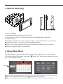
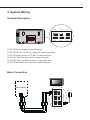
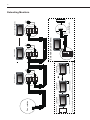
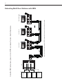
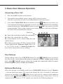
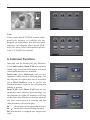
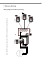
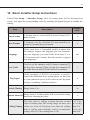
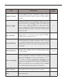
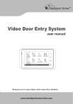
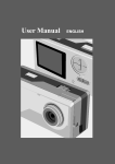
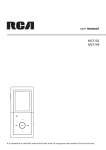
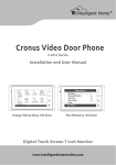
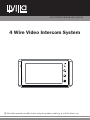
H4.27SDD USER MANUAL(EN) 4 Wire Video Intercom System 1 2 3 4 Read this manual carefully before using the product, and keep it well for future use. Contents 1. Parts and Functions...............................................................................1 2. Monitor Mounting....................................................................................2 3. About Main Menu...................................................................................2 4. System Wiring........................................................................................3 5. Basic Door Release Operation...............................................................7 6. Intercom Function...................................................................................8 7. Memory Sharing ....................................................................................9 8. Album Playback(for SD card model only)...............................................10 9. Basic Setup Instructions.........................................................................12 10. Basic Installer Setup Instructions........................................................13 11. Monitor Advanced Setting.....................................................................15 12. Specification.........................................................................................16 -1- 1. Parts and Functions Digital TFT LCD Screen Indicator 1 Indicator 2 Microphone UNLOCK Button TALK/MON Button 1 2 3 MENU Button 4 Mounting Hook Speaker Connection Port Mounting Hook SD card slot Key functions LCD screen Display the visitors' image Indicator1 Show the working status of monitor Indicator2 Light on when the recorded pictures have not been viewed Unlock button Press to release the door Talk/Mon button Press to communicate hands free with visitor Press to view the outdoor condition in standby mode Press to turn off staircase light,refer to part 3 Menu button Press twice to open the menu shortcuts. Microphone Receive voice from the user Mounting hook Use to hang up the monitor Connection port Bus terminal Speaker Send out vioce from the visitor -2- 145~160 cm 2. Monitor Mounting Accessory fittings: 1) Mounting Bracket and special 4 core wire 2) Two screws of 4X25 are used to fasten the Mounting Bracket on the wall. Installation steps: ■ Installation Height for indoor monitor usually is 145- 160CM (refer to sketch map) ■ Attach the screws to the wall to fix the mounting bracket. ■ Refer to the system connection section of this manual, connect wires correctly. ■ Hang the monitor firmly on the bracket. 3. About Main Menu The Main Menu is your starting point for using all the applications on your monitor. To open the Main Menu page, tap either " Menu" key twice on the monitor or press the screen anywhere twice. Current date Current time 04:29PM Manual Monitor Monitor Intercom Inner Call Memory Playback Album User Setup Close :This icon will be displayed when the staircase light item is light on if the system connect VT-RLC module which control light. otherwise,it won't be displayed.Touching this icon or pressing TALK/MON button can turn off the light. :This icon will be displayed when the recorded pictures have not been viewed,touching this icon can see the recorded pictures. -3- 4. System Wiring Terminal Discription Power JP/VD DC-IN DC- DC+ 4B Input 1 JS-VD 1R 2W 3Y 4B JS-OS2 1R 2W 3Y 4B JS-OS1 1R 2W 3Y 4B 2W 75 Ohm JS-AP 12V Handset Input 2 Output 1) DC-IN:Power supply connection port 2) JP/VD:JP/VD is used for setting the video impedance. 3) JS-AP:Audio phone or VT-RLC connection port 4) JS-OS1:The first door station connection port 5) JS-OS2:The second door station connection port 6) JS/VD:Extended slave monitor connection port Basic Connection 1 2 3 4 Black Red White Yellow 1R 2W 3Y 4B Black Power Red 75 Ohm White AC ~ Reserve DC-IN DC- DC+ JP/VD 1R 2W 3Y 4B 4B Handset 2W JS-AP Output 1R 2W 3Y 4B JS-VD Input 2 1R 2W 3Y 4B 12V JS-OS2 1R 2W 3Y 4B JS-OS1 Input 1 Yellow Door station PS 4B 2W 12V JP/VD 1R 2W 3Y 4B JS-OS2 Reserve JS-VD DC-IN DC- DC+ Note:To the first & last monitor,JP/VD jumper should reserve! others should remove. PS 1R 2W 3Y 4B JS-AP JP/VD Reserved 4 3 2 JS-OS1 JP/VD Removed! 4 1R 2W 3Y 4B Back View 4 3 2 White Black Red White Black Red 4B 2W 12V Back View GX-3P JS-AP 4B 2W +12 JS-LK AC ~ INSIDE (90 Degree ROTATE) JS-VD JP/VD Reserved 3 4 PS 2 3 1 DC- DC+ 2 4 DC-IN 1 1R 2W 3Y 4B 1R 2W 3Y 4B 1R 2W 3Y 4B DC- DC+ 1 4 JS-VD Extending Audio Phone: AC ~ DC-IN 1 N# Monitor User code=N(N<5) 4B 2W 12V Back View 4 3 2 1 User code=N(N<5) Reserve 4 2# Monitor User code=2 JP/VD User code=1 JS-OS2 1R 2W 3Y 4B 1R 2W 3Y 4B 1R 2W 3Y 4B Remove Camera AC ~ 4 3 2 1 JP/VD 1R 2W 3Y 4B 4B 2W 12V Back View JS-OS1 1R 2W 3Y 4B 1R 2W 3Y 4B JS-AP JS-OS2 1# Monitor Door station 4 3 2 1 User code=2 JS-OS1 JP/VD Red JS-AP JS-OS2 Black JS-OS1 White JS-AP Yellow User code=1 -4- Extending Monitors JS-VD DC-IN DC- DC+ 1# Camera 1R 2W 3Y 4B 1R 2W 3Y 4B 1R 2W 3Y 4B 4B 2W 12V Back View JP/VD Reserve JS-VD 2 3 4 3 4 JP/VD Removed! 2# Monitor User code=2 AC ~ PS 4 N# Monitor JP/VD Reserved 4 3 2 1 4B 2W 12V Back View User code=N(N<5) 1R 2W 3Y 4B 1R 2W 3Y 4B 1R 2W 3Y 4B AC ~ PS NOTE: 1.To the first & last monitor,JP/VD jumper should reserve! others should remove. 2.When connect two Outdoor Stations, 2 Way Input item should be set to 1 on the 1# Monitor. (Main Menu-User Setup-Installer Setup-2 Way Input) JP/VD Reserve! 1 2 DC-IN 1 PS 4 DC- DC+ 4 4 4B 2W 12V Back View Remove 1# Monitor User code=1 1R 2W 3Y 4B 1R 2W 3Y 4B 1R 2W 3Y 4B 4 3 2 1 User code=N(N<5) DC- DC+ 2# Camera 1# Camera AC ~ 4 3 2 1 User code=2 DC-IN 2# Camera 4 3 2 1 JS-OS2 Red JS-OS1 JP/VD JS-VD Red JS-AP JS-OS2 Black JS-OS1 JP/VD White JS-AP JS-OS2 Yellow JS-OS1 Black Reserve White JS-AP Yellow User code=1 -5- Extending 2 Outdoor Stations JS-VD DC-IN DC- DC+ 1# door station 2# door station 3# door station DS2 JW_VP DS1 JW_VP JS-OS1 JS-OS2 JP/VD Reserve 2W JS-AP Red DS4 12V White DS3 4 3 2 4B 1R 2W 3Y 4B Yellow JS-VD DC- DC+ DC-IN JS-AP 4 3 2 1 JS-OS1 2W 1 1R 2W 3Y 4B 12V SET White Yellow Red Black JS-OS2 JP/VD Remove JS-VD DC- DC+ DC-IN JS-AP 4 3 2 1 JS-OS1 JS-OS2 JP/VD Reserve JS-VD DC- DC+ DC-IN User code=N(N<5) Note:To the first & last monitor,JP/VD jumper should reserve! others should remove. 4B 3Y 2W 1R Black 1R 2W 3Y 4B VT-MDS 1R 2W 3Y 4B 4B 1R 2W 3Y 4B 2W 4# door station 1R 2W 3Y 4B 12V User code=2 1R 2W 3Y 4B 4B 1R 2W 3Y 4B User code=1 1R 2W 3Y 4B CCTV or Door station 1R 2W 3Y 4B About the MDS instructions ,please refer to MDS user manual for more detail informations. -6- Extending Multi Door Stations with MDS -7- 5. Basic Door Release Operation Answering a Door Call 1. Press the CALL button on door station. 2. The monitor rings,and the visitor's image will be seen on screen. Note:the screen turns off after 30 seconds(default) if nobody answers. 3. Press either TALK/MON Button on monitor or touch Talk icon on screen, you can communicate hands free with the visitor for 90 seconds(default).After finishing communication,press TALK/MON button or touch Talk icon again to end the communication. If the system connects two or more Monitors, pick up any Monitor, the others will be automatically shut off. Status bar ►►1.show the current door station for monitoring. ►►2.show the waiting time for calling. ►►3.if the monitor is set to silence mode,this icon will be shown. ►►4.if the system connect VT-RLC module which control light,and the Staircase Light item is set to 1or 2 (refer to part 9->Staircase Light),this icon will be shown when receive calling. 1 2 3 4 DS1 00:30 Door Release During talking state, Press UNLOCK Button or touch Unlock1 icon to release the door for the visitor.(Note:if the system is connected VT-RLC module which control lock, touch Unlock2 icon to release the second lock connected to RLC,for more information,please refer to VT-RLC user manual. ) Entrance Monitoring When the monitor is in standby mode, press TALK/MON Button(or touch Monitor ... item on main menu page), The screen can display the view of outside. If multi door stations are installed, touch Select icon to get into the camera switch mode(or directly touch Manual Monitor item on main menu page). Select door 1/2/3/4 to monitor the door station or CCTV camera you want.See the following diagrams. -8- DS-1 00:23 Note: If the system install VT-QSW module,video quad split monitor is available,see the diagram on right(please note that the quad interface just display when install QSW unit).for more detail information,please refer to VT-QSW user manual. Door 1 Door 2 Door 3 Door 4 Door 1 Door 2 Door 3 Door 4 Camera 1 Camera 2 Camera 3 Quad 6. Intercom Function Intercom can be initiated by any Monitor. Touch Intercom or Inner Call item on main menu page. Intercom function is activated when multi monitors are installed. Intercom: press Intercom icon on any monitor to enter selective intercom page, see the diagram on right.select one of user,then press Dial Number icon to call.If the selected monitor answers the call,intercom talking is strating. Inner Call: press Inner Call icon on any monitor to enter selective intercom page, see the diagram on right.All monitors will ring at the same time,whichever monitor answers the call, conversation is starting.and the other monitors will stop ringing . ►►“ !” means the current operating monitor. ►►“ ” means the selected calling monitor. ►►Each monitor is configed one unique user code Selective Intercom ! User 1 User 2 1 2 User 3 User 4 User 5 Dail Number Return Selective Intercom User 1 User 2 Redial User 3 User 4 User 5 Dail Number Return Door station 4 3 2 1 1R 2W 3Y 4B 1R 2W 3Y 4B 1R 2W 3Y 4B 4B 2W 12V Back View JP/VD Red JS-OS2 Black JS-OS1 White JS-AP Yellow User code=1 VT27SD/TD7 AC ~ Reserve JS-VD DC-IN DC- DC+ SET-3Y 150R 75R HI SET-3Y VT-BDU JW/VP3 1R 2W 3Y 4B JW/VP2 1R 2W 3Y 4B JW/VP1 1R 2W 3Y 4B JW/OS 1R 2W 3Y 4B User code=N(N<5) VT-BDU JP/VD Reserved 4 3 2 AC ~ JP/VD Reserved 4 3 2 1 VT27/TD7 1 AC ~ User code=3 VT27/TD7 JP/VD Reserved 4 3 2 1 VT27/TD7 User code=2 About the BDU instructions ,please refer to BDU user manual for more detail informations. AC ~ -9- 7. Memory Sharing Wiring Diagram for Memory Sharing -10- Memory sharing means that the slave monitors(user code=2/3/4/5,refer to part 9->user code) can view the pictures from the master monitor(user code=1,refer to part9->user code),but the master monitor must be with SD card model which has picture memory function.Touch Memory Playback icon on main menu page. ►►4 pictures will be displayed in each memo. ►►The newest pictures will be displayed in the first memo. ►►When the built-in memory is full(max.800 pictures),the oldest picture will be deleted to make room for new record. Note:the user code of the master monitor must be set to 1,otherwise the memory function is unavailable. Last 2011-09-13 004 2011-09-13 003 Next Delete 2011-09-13 002 2011-09-13 001 Home About Picture Memory Recording You can setup Memo Options to choose 1/4/8 pictures memo. If 4/8 was chosen, you will have 4/8 shots for each recording operation, every 1.5 seconds catch a picture. Please refer to part 9->Picture Memory. 8. Album Playback(for SD card model only) Touch Album on main menu page to play photos(must plug in SD card).it can be played automatically or manually by using your fingers to slide right or left on screen to play last or next photo.To finish the ablum playing,please touch the screen and hold for 2 seconds or touch " Menu" key. Playing time setting You can set the maxmum album playing time,range from 1~999 minutes. Please refer to part 9->Album Playback. -11- Date and Time Setting There are two formats for date and time display, refer to part 9->date/time format. Touch User Setup ->>Calendar. use "cancel" key to select the setting item. After finishing, touch "save" key to perform the setting. 2011-09-13 16:30 Day Time Setting The day time setting is used to distinguish the day ring volume and night ring volume.07:00 AM~18:00 PM is the default day time .Touch User Setup ->>Day Time. Use "cancel" key to select the setting item. After finishing, touch "save" key to perform the setting. [07:00] --[18:00] Restore to Default Touch User Setup ->> Restore to default ,a message will be asked to confirm the restore operation. touch Restore to default icon again ,All settings will be restored to default except Calendar item. Master Call tone Slaver Call tone Intercom Call tone Ring Volume Night Ring Volume Monitor Time Calendar Day Time Installer Setup Restore to default Restore To Default ? Screen Setting During monitoring or talking state, touch Adjust icon,the Adjust page will be displayed. The first item is Scene mode selection: Total 4 screen modes can be selected in sequence: Normal, User, Soft and Bright. The Brightness and Color item is for the image quality setting. The Talk Volume item is for talking volume adjustment. Bright Color 5 Scene Talk Vol Return -12- 9. Basic Setup Instructions Ring Tone Settings Touch User Setup item on main menu page to enter setup page.Select Master Call Tone, Slaver Call Tone or Intercom Call Tone item, There are 12 pieces ring tones can be selected.touch a ring tone you want, then touch icon to save and return last page.but if you don't want to save the settings, touch icon to exit. Master Call Tone :set the ring tone calling from master door station which is connected to JS/OS1 terminal of monitor. Slaver Call Tone :set the ring tone calling from slaver door station(Door 2/3/4). Intercom Call Tone :set the ring tone calling from intercom call or inner call. Ring Volume and Night Ring Volume Setting You can set a ring volume for day time and night time individually, 07:00 AM~18:00 PM is the day time by default, but the day time can be modified at any time by yourself(refer to Day time setting section for more detail information). Touch User Setup item on main menu page to enter setup page,select Ring Volume or Night Ring Volume to set a appropriate value.if you don't want to be disturbed at night,you can set the night ring volume to 0. 6 Monitor Time Setting Touch User Setup ->>Monitor Time. A digital keypad will be shown on screen, input the monitor time by touching the digital keypad,range from 00:30 ~ 59:59. use "cancel" key to select the setting item. After finishing, touch "save" key to perform the setting .(touch icon to return last page.) [01:30] -13- 10. Basic Installer Setup Instructions Touch User Setup ->>Installer Setup, total 16 setting items will be displayed on screen. Just input the corresponding value by touching the digital keypad to modify the setting. Description Default value Time Format 2 formats can be selected.[0]:24 hours format;[1]:12 hours format. 0 Date Format 2 formats can be selected.[0]:day/month/year format;[1]:month/day/year format. 0 Language If this item show 1-1(standard model),it means that the monitor support one language,you can customize any one language you want.If this item show 2-1 or 2-2(customized),it means that the monitor support two languages. one User Code Used to set the monitor code,[1]:master monitor;[2] the first slave monitor;[3]the second slave monitor;[4] the third slave monitor;[5] the fouth slave monitor 1 2 Way Input If the terminal of JS/OS2 on monitor is used to extend the additional door station,please set this item to 1(on),otherwise,set to 0(off).(refer to part 4(system wiring->extending 2 outdoor station)) 0 Unlock Timing Range from 0~9s. 3s Unlock Auto Off Range from 0~9s,the monitor will be closed in setting time after releasing the door. 0 Item The first value is calling waiting time.the second value is talking time.The setting range for these two Calling Timing values are from 03-60,please note that the calling time is setting value multiply ten.For example,the setting value is 03,the calling time is 30s calling waiting time:30s talking time:90s -14- Description Default value Remote Control Used to add the remote controller or delete remote controller,[0]:delete remote control;[1]:add remote control. 0 Staircase Light staircase light can be set.[0]:don't light on at any time when receive calling;[1]:light on at night only when receive calling;[2]light on at any time when receive calling.Note that this item should be set on master monitor(user code=1),for slave monitors,this item is invalid. 0 BDU installed Range from 0~1.when the system install VT-BDU module,this item must set to 1. 0 Picture Memory Set the numbers for capture pictures, only 1/4/8 can be set.Note that this item should be set on master monitor(user code=1),for slave monitors,this item is invalid. 1 Album Playback Set the max. playing time for album,range frome 1~999 minutes. 10 mins Item Restore parameter settings to default value,touch Recover Settings icon,an information of "Y/ N" will be asked,touch Recover Settings icon Recover Settings... again,restore setting will be performed immediately. Please note that the recover setting will not change time format,date format and user code item. _ Online Search... Search the devices connected to the system _ Back Return last page _ -15- 11. Monitor Advanced Setting Touch "About" button on main menu page,the monitor current parameters will be shown on screen,at this page,press Unlock button and hold for 3s,a digital keypad will be shown,input the code number by touching the keypad,touch "cancel" button to cancel the input,touch "save" button to confirm the settings. Item Volume setting Code Description Default value 8800~8899 Set the volume for intercom talking,including the microphone and speaker,the larger you set,the weaker it will be. 8800 Set the talking volume with outdoor station,including the microphone and loud 8900~8999 speaker,the larger you set,the weaker it will be. 8900 8630 There is not any logo to display when close the monitor. 8631 Input this code number to display the logo when close the monitor. Factory setting 2412 Restore to factory setting,including user setup,installer setup,and format pictures. _ Initialization setting 2499 Restore to initialization setting,including user setup,installer setup, format pictures,logo status,volume setting. _ Resver 6789 Resver _ NTSC/PAL setting 8500~8502 Logo status setting There are three setting modes: 8500(Auto identification mode);8501(PAL standard mode;8502(NTSC standard) mode 8630 8500 -16- 12. Specification ●● Power Supply: ●● Power Consumption: ●● Monitor Screen: ●● Display Resolution: ●● Built-in Memory: ●● Picture Memo: ●● Wiring: ●● Monitor time: ●● Talking time: ●● Dimensions: DC16-24V standby 1.2W,working 8W 7 inch digital TFT 800*3(RGB)*480 pixels 120 MB 800pcs(inner memory), >30000pcs(2G SD card) 4 wires, polarity 30 seconds(default) 90 seconds(default) 125(H)×225(W)×23(D)mm Notes The design and specifications can be modified without notice to the user. Right to interpret and copyright of this manual are preserved.