1
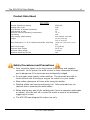
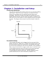
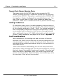
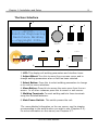
AC1025 User Manual Copyright 2009 Sunstone Engineering R&D Inc. 2 Contents The AC1025 AC Spot Welder........................................ 4 Features............................................................................. 4 Product Data Sheet.............................................................. 5 Safety Procedures and Precautions ........................................5 Chapter 1: Installation and Setup................................ 6 Positioning Guidelines........................................................... 6 Foot Switch Setup................................................................ 6 Power Cord, Power Source, Fuse............................................ 7 Cabling Guidelines............................................................... 7 Heat Considerations............................................................. 7 The User Interface............................................................... 8 Jobs and Schedules.............................................................. 9 Chapter 2: Spot Weld Function.................................... 10 Theory of Operation............................................................. 10 Weld Parameter Definitions................................................... 11 Example Walkthrough........................................................... 12 Chapter 3: Rolling Spot Weld Function........................ 13 Theory of Operation............................................................. 13 Weld Parameter Definitions................................................... 14 Example Walkthrough........................................................... 15 Chapter 4: Seam Weld Function................................... 16 Theory of Operation............................................................. 16 Weld Parameter Definitions................................................... 16 Example Walkthrough........................................................... 17 Chapter 5: Pulsating Spot Weld Function..................... 18 Theory of Operation............................................................. 18 Weld Parameter Definitions................................................... 19 Example Walkthrough........................................................... 20 Chapter 6: Main Menu Functions.................................. 21 Beep Toggle........................................................................ 21 Add a Schedule................................................................... 21 Lock a Schedule.................................................................. 21 Copy a Schedule.................................................................. 21 Restart the Schedule Counter................................................ 22 Restart Current Job.............................................................. 22 Tempering Function.............................................................. 22 View the Internal Temperature............................................... 22 AC1025 User Manual 3 Chapter 6: Main Menu Functions (Cont.) View the Lifetime Weld Counter.............................................. 23 View Welder Information....................................................... 23 Chapter 7: Job Menu Functions and Chaining.............. 23 Chain and Unchain Schedules................................................ 23 Link a Schedule to the Chain................................................. 23 Remove Last Link from the Chain........................................... 24 Change the Number of Welds for a Link.................................. 24 Chapter 8: Other Welder Functions.............................. 24 Resetting to Factory Defaults................................................. 24 Appendix A: Cable Resistance Chart............................ 25 Appendix B: Menu Flowcharts..................................... Error! Bookmark not defined. Main Menu.......................................................................... Error! Bookmark not defined. Job Menu............................................................................ 27 Appendix C: Glossary................................................... 28 Appendix D: Warranty and Contact Information.......... 29 Sample Job Documentation Layout.............................. 30 NOTE: The information contained in this manual is subject to change as improvements are made to our products. Visit www.SunstoneEngineering.com for the latest version of this AC1025 User Manual 4 document. AC1025 User Manual The AC1025 AC Spot Welder 5 The AC1025 AC Spot Welder Features Embedded digital microprocessor with internal memory space for 100 user programmable welding schedules. Ability to link multiple schedules together into a job chain. Five welding types: Single Pulse Spot Weld Dual Pulse Spot Weld Auto-Repeating Roll Spot Weld Seam Weld Multi-Pulse Spot Weld Internal 2.5 kVA welding transformer means no costly external equipment. Automatic internal thermal protection with audible alarm. Simple digital user interface with short learning curve. Tempering function to slowly cool completed welds. On-screen weld counter keeps track of how many welds have been completed and can automatically switch schedules after the programmed number of welds. Automatic lifetime weld counter will help keep track of daily, monthly, or yearly weld output. Included foot switch for weld firing control. Accidental schedule overwrite protection through lock-out feature. Small enclosure footprint means more mobility and less table-top space required. AC1025 User Manual The AC1025 AC Spot Welder 6 Product Data Sheet AC1025 Internal Transformer Rating Welding Duty Cycle Total Number of Savable Schedules Total Number of Jobs Maximum Internal Operating Temperature Fuse Rating Power Supply Requirements Weight Case Dimensions (L X W X H without terminals, with feet) Power Cord Length Minimum Pulse Length Maximum Pulse Length Maximum Welds Per Minute 2500 kVA 50% 100 10 75 °C 20A 220-240VAC 50-60Hz 32 lbs (14.5 kg) 13¼” X 10” X 5½” (33.6 cm X 25.4 cm X 13.9 cm) 5½' (168 cm) 16.67 ms 1.65 sec 180 Safety Procedures and Precautions Care should be taken not to short across the positive and negative terminals. At full power, the weld current is many thousands of amps and is dangerous if the terminals are accidentally bridged. Do not wear metal jewelry when welding. The terminals are safe to touch without fear of arcing as long as no metal is on your hands. Wear safety glasses at all times while using the welder. Welding cables can become extremely hot. After extended use, be cautious when removing the weld cables. When altering any part of the welding path (such as swapping electrodes or cables), turn the unit off or enter the menu to ensure no accidental triggering of a weld. The AC1025 was designed for indoor use only. AC1025 User Manual Chapter 1: Installation and Setup 7 Chapter 1: Installation and Setup Positioning Guidelines The goal when deciding the location of the unit is to minimize welding cable length. Place the unit on a tabletop or workbench directly behind your workspace with the welding terminals facing your workspace. Keep the unit away from edges to avoid the risk of the welder falling to the floor. Be sure there is at least 6” of space on all sides and on top of the welder to ensure adequate cooling throughout the case. The diagram below shows the airflow direction inside the unit. Exhaust Front Airflow Rear Intake Foot Switch Setup The included foot switch can be plugged into the rear panel of the welder into the Ext. Trigger port. To attach the coupling, push it into the port and then secure it by twisting the ring clockwise until tight. Do not force the coupling as it can only be inserted in one orientation. When using the foot switch to trigger a weld, keep in mind that some of the welding functions require the switch to be simply depressed and released, while others require a prolonged depression corresponding with desired weld time. See the chapters on each specific weld function for more information (Chapters 2-5). AC1025 User Manual Chapter 1: Installation and Setup 8 Power Cord, Power Source, Fuse The power cord on the AC1025 can only be connected to 220240VAC, 50-60Hz electricity. NEVER use a power strip or extension cords with the AC1025. The welder is protected with a 250VAC, 20A time-lag fuse. Replace the fuse with a compatible device only. The rear of the unit also has a 250VAC circuit breaker as added user protection. Make sure it is switched into the up position before using. Cabling Guidelines For maximum power output, the cabling between the terminals and the work piece should be as short as possible. The optimal resistance for the complete weld path is .3mΩ - .5mΩ. The internal resistance from the secondary transformer winding to the terminals is .02mΩ. A recommended cable configuration that has been thoroughly tested with a weld head is to use 1.5' 1AWG cable lengths on both terminals. A chart of cable resistances and gages can be found in Appendix A. Heat Considerations After extended use, the welding cable and terminals will become extremely hot. While the unit monitors the internal transformer and relay temperature it cannot monitor the external cables. Be sure to use cables with a suitable temperature rating for your application to avoid cable failure. In the event of internal overheating, the unit will beep three times and display a status message with the internal temperatures. During this time, none of the welder's functions will operate. Once the heat levels have fallen to acceptable levels, the unit will beep twice and resume normal operation. If the heat alarm occurred during a weld, the remainder of the weld will be canceled. AC1025 User Manual Chapter 1: Installation and Setup 9 The User Interface 1 2 4 3 -------AC1025------Sunstone Engineering Resistance Welding ---Copyright 2009--Adjust Select Menu Power On 5 Off 6 1. LCD: This displays all welding parameters and interface items. 2. Adjust Wheel: Turn this to move the on-screen cursor and to change welding parameters when a field has been selected. 3. Select Button: Press this to select welding parameters to change or to confirm menu selections. 4. Menu Button: Press this to access the main menu from the run screen. In all other instances press this to cancel or exit menus. 5. Welding Terminals: Connect welding cable to these terminals using the included fasteners. 6. Main Power Switch: This switch powers the unit. *For more detailed information on the run screen, see the chapter corresponding to the weld function you wish to use (Chapters 2-5). For more information on the menus, see Chapters 6-7. AC1025 User Manual Chapter 1: Installation and Setup 10 Jobs and Schedules When the welder arrives from the factory, it is configured with 10 jobs numbered 0-9. Each job has schedule 0 activated. Schedule 0 is the “scratch-pad” schedule that you can use to develop weld configurations that work with your applications. Each job can have up to 9 additional schedules added to it for a total of 100 schedules. You must use the menu function Add a Schedule to add schedules to the current job. The current job and current schedule are displayed in the upper left portion of the run screen. Any changes made to a schedule's parameters are immediately saved to memory. A visual representation of a sample job/schedule architecture is given below. Job 1 Job 2 Job 3 Sch 1 Sch 1 Sch 1 Sch 2 Sch 2 Sch 2 Sch 3 Sch 3 Sch 3 Sch 4 Sch 4 Sch 4 ... ... ... AC1025 User Manual ... Chapter 2: Dual Pulse Spot Weld Function 11 Chapter 2: Dual Pulse Spot Weld Function Theory of Operation The Dual Pulse Spot Weld Function is the default function for newly added schedules and provides the most flexible welding option. Two pulses are desirable in many applications because a pre-welding pulse can reduce splash as well as remove any surface impurities that might hamper the main welding pulse. On the AC1025, the two pulses can be programmed to whatever power level and length is desired and can even be shut off for single pulse operation. The initial pulse's power is controlled by the Pow1 parameter and is displayed as a percentage of maximum power. Its length is governed by the Cyc1 parameter and is given in units of AC cycles where: 1 AC cycle = 1 = 16.67ms 60Hz The time between pulses is represented by the Pspace parameter and is also given in units of AC cycles. The second pulse operates similarly to the first and its power and length are controlled by the Pow2 and Cyc2 parameters respectively. Either pulse can be any percentage of maximum power you choose and at most, 99 AC cycles long. Additionally, the spacing between pulses can be any length you choose up to 99 AC cycles. To deactivate a pulse, set either its power or cycle length to 0 and that pulse will be ignored. To initiate the weld, be sure the run screen is displayed and not any of the menu screens. Depress the foot switch and then release it to make the weld. As part of the unit's heat management protocols, a waiting period equal to the total welding time begins immediately after each weld during which another weld cannot be initiated. For example: 8 cyc for pulse135 cyc for pulse2= 43cyctotal wait time If audible beeps are activated, a short chirp will signal that the unit is ready to weld again. AC1025 User Manual Chapter 2: Dual Pulse Spot Weld Function 12 Weld Parameter Definitions 1 2 3 5 4 Dual Pulse Spot Weld 100% 90% 80% 70% 9 11 8 7 60% 10 ' 50% 40% 30% 20% 6 ' 7 AC Power 6 8 J:1 ►S:4 F:Spot S Pow1: 40% Cyc1: 3 PSpace: 2 Count: 54 Pow2:100% Cyc2:5 10% 10 11 0% 0 1 2 3 4 5 6 7 8 9 10 11 12 AC Cycles 1. Current Job: Displays the current job number. 2. Cursor: The cursor indicates the current changeable parameter. 3. Current Schedule: Displays the current schedule number. 4. Weld Function: Displays the current weld function. 5. Select Toggle Indicator: 'S' indicates that turning the Adjust Wheel will adjust the currently selected parameter. A blank space indicates that turning the Adjust Wheel will move the cursor. 6. Pulse One Power: Percentage of maximum power for pulse one. 7. Pulse One Length: Length in AC cycles for pulse one. 8. Pulse Spacing: Space in AC cycles between pulses one and two. 9. Current Weld Count: Displays the number of welds that have been made with the current job. Can be reset to zero by selecting the Reset Schedule Counter option from the main menu. 10. Pulse Two Power: Percentage of maximum power for pulse two. 11. Pulse Two Length: Length in AC cycles for pulse two. AC1025 User Manual Chapter 2: Dual Pulse Spot Weld Function 13 Example Walkthrough This walkthrough will provide a step-by-step guide for making a dual pulse spot weld with some common weld parameters. Press the Menu Button to access the main menu Menu Move the cursor down to Add Schedule and press Select Adjust Select Press the Menu Button to exit the main menu Menu Move the cursor to Pow1 and press Select Adjust Select Adjust Pow1 to 50% and then press Select Adjust Select Adjust Select Adjust Select Adjust Select Adjust Select Adjust Select Adjust Select Adjust Select Adjust Select Move the cursor to Cyc1 and press Select Adjust Cyc1 to 5 cycles and press Select Move the cursor to PSpace and press Select Adjust PSpace to 2 cycles and press Select Move the cursor to Pow2 and press Select Adjust Pow2 to 100% and press Select Move the cursor to Cyc2 and press Select Adjust Cyc2 to 15 cycles and press Select When the workpiece is in position, and the LCD appears as shown, depress J:0 S:1 F:Spot the foot switch to make the weld. Pow1: 50% Cyc1: 5 Pspace: 2 Count: 0 Pow2:100% ►Cyc2:15 AC1025 User Manual Chapter 3: Rolling Spot Weld Function 14 Chapter 3: Rolling Spot Weld Function Theory of Operation The Rolling Spot Weld Function provides a way to repeat single pulses of welding current for as long as the user depresses the foot switch, subject only to internal temperature limits. This function would typically be used in conjunction with specialized rolling weld heads. The pulse power is controlled by the Pow parameter and is given as a percentage of maximum power. The pulse length is controlled by the Cycles On parameter and is given in units of AC cycles where: 1 1 AC cycle = = 16.67ms 60Hz The time between successive pulses is governed by the Cycles Off parameter and is also given in units of AC cycles. The power of the repeated pulse can be any percentage of maximum power and up to 99 AC cycles long. The time between cycles can be between 1 and 99 AC cycles. To initiate the weld, be sure the run screen is displayed and not sny of the menu screens. Depress the foot switch for as long as you want the pulses to continue. Release the foot switch to end the welding pulses. As part of the unit's heat management protocols, the welding pulses may end unexpectedly if the internal temperature exceeds the predefined limits. In such an event, an audible alarm will sound. To resume welding, release the foot switch and wait until the internal temperature falls into a normal range. If audible beeps are activated, a short chirp will signal that the unit is ready to weld again. AC1025 User Manual Chapter 3: Rolling Spot Weld Function 15 Weld Parameter Definitions 1 2 3 4 5 Rolling Spot Weld 70% 8 9 50% 7 40% 30% 6 6 66 ' S 3 8 ' J:1 ►S:4 F:Roll Pow: 50% Count: Cycles On: 3 Cycles Off: 2 AC Power 6 8 9 60% 20% 10% 9 0% 0 1 2 3 4 5 6 7 8 9 10 11 12 AC Cycles 1. Current Job: Displays the current job number. 2. Cursor: The cursor indicates the current changeable parameter. 3. Current Schedule: Displays the current schedule number. 4. Weld Function: Displays the current weld function. 5. Select Toggle Indicator: 'S' indicates that turning the Adjust Wheel will adjust the currently selected parameter. A blank space indicates that turning the Adjust Wheel will move the cursor. 6. Pulse Power: Percentage of maximum power for each pulse. 7. Current Weld Count: Displays the number of welds that have been made with the current job. Can be reset to zero by selecting the Reset Schedule Counter option from the main menu. 8. Pulse Length: Length in AC cycles for each pulse. 9. Pulse Spacing: Space in AC cycles between subsequent pulses. AC1025 User Manual Chapter 3: Rolling Spot Weld Function 16 Example Walkthrough This walkthrough will provide a step-by-step guide for making a rolling spot weld with some common weld parameters. Press the Menu Button to access the main menu Menu Move the cursor down to Add Schedule and press Select Adjust Select Press the Menu Button to exit the main menu Menu Move the cursor to Pow and press Select Adjust Select Adjust Pow to 75% and then press Select Adjust Select Adjust Select Adjust Select Adjust Select Adjust Select Move the cursor to Cycles On and press Select Adjust Cycles On to 15 cycles and press Select Move the cursor to Cycles Off and press Select Adjust Cycles Off to 30 cycles and press Select When the workpiece is in position, and the LCD appears as shown, depress the foot switch for as long as is desired, then release to end the weld. J:0 S:1 F:Roll Pow: 75% Count: Cycles On: 15 ►Cycles Off: 30 AC1025 User Manual 0 Chapter 4: Seam Weld Function 17 Chapter 4: Seam Weld Function Theory of Operation The Seam Weld Function provides a non-stop pulse of welding current for as long as the user depresses the foot switch. Like the Rolling Spot Function, the length of the pulse is subject only to internal temperature controls and is typically used with specialized rolling weld heads. The purpose of the Seam Weld Function is to create a linear shaped weld nugget on the faying surfaces. The pulse power is controlled by the Pow parameter and is given as a percentage of maximum power. The pulse length is controlled entirely by the depression of the foot switch and will end only when the switch is released or if the internal temperature protocols engage. The weld can only be initiated from the run screen and not in a menu. If audible beeps are activated, a short chirp will signal that the unit is ready to weld again. Weld Parameter Definitions 1 2 3 4 Seam Weld 5 100% 90% 80% S 3 70% 7 60% 50% 6 40% ' F:Seam Count: AC Power 6 J:1 ►S:4 Pow: 80% 30% 20% 10% 0% 0 1 2 3 4 5 6 7 8 9 10 11 AC Cycles 1. Current Job: Displays the current job number. 2. Cursor: The cursor indicates the current changeable parameter. 3. Current Schedule: Displays the current schedule number. 4. Weld Function: Displays the current weld function. 5. Select Toggle Indicator: 'S' indicates that turning the Adjust Wheel will adjust the currently selected parameter. Nothing indicates that turning the Adjust Wheel will move the cursor. 6. Pulse Power: Percentage of maximum power for pulse. AC1025 User Manual 12 Chapter 4: Seam Weld Function 18 7. Current Weld Count: Displays the number of welds that have been made with the current job. Can be reset to zero by selecting the Reset Schedule Counter option from the main menu. Example Walkthrough This walkthrough will provide a step-by-step guide for making a seam weld with some common weld parameters. Press the Menu Button to access the main menu Menu Move the cursor down to Add Schedule and press Select Adjust Select Press the Menu Button again to exit the main menu Menu Move the cursor to Pow and press Select Adjust Adjust Pow to 85% and then press Select Adjust Select Select When the workpiece is in position, and the LCD appears as shown, depress the foot switch for as long as is desired, then release to end the weld. J:0 S:1 ►Pow: 85% F:Seam Count: AC1025 User Manual 0 Chapter 5: Pulsating Spot Weld Function 19 Chapter 5: Pulsating Spot Weld Function Theory of Operation The Pulsating Spot Weld Function is similar in operation to the Rolling Spot Function. Unlike the Rolling Spot though, this function adds the ability to precisely control the number of weld pulses generated. Each pulse's power is controlled by the Pow parameter and is displayed as a percentage of maximum power. Each pulse's length is governed by the Cyc parameter and is given in units of AC cycles where: 1 AC cycle = 1 = 16.67ms 60Hz The time between pulses is represented by the Cycles Off parameter and is also given in units of AC cycles. Lastly, the total number of pulses is controlled by the Pulses parameter and is unitless. The pulses can be any percentage of maximum power you choose and at most, 99 AC cycles long. Additionally, the spacing between pulses can be any length you choose up to 99 AC cycles. The maximum number of pulses that can be generated is 99. To initiate the weld, be sure the run screen is displayed and not any of the menu screens. Depress the foot switch and then release to make the weld. If audible beeps are activated, a short chirp will signal that the unit is ready to weld again. AC1025 User Manual Chapter 5: Pulsating Spot Weld Function 20 Weld Parameter Definitions 1 2 3 4 Pulsating Spot Weld 5 8 100% 90% 10 10 70% 9 7 60% 7 7 50% 6 40% ' 7 AC Power 6 8 J:1 ►S:4 F:Pulse S Pow: 80% Cyc: 3 Pulses: 3 Count: 5 Cycles Off: 1 80% 30% 20% 10% 0% 10 0 1 2 3 4 5 6 7 8 9 10 11 12 13 AC Cycles 1. Current Job: Displays the current job number. 2. Cursor: The cursor indicates the current changeable parameter. 3. Current Schedule: Displays the current schedule number. 4. Weld Function: Displays the current weld function. 5. Select Toggle Indicator: 'S' indicates that turning the Adjust Wheel will adjust the currently selected parameter. A blank space indicates that turning the Adjust Wheel will move the cursor. 6. Pulse Power: Percentage of maximum power for each pulse. 7. Pulse Length: Length in AC cycles for each pulse. 8. Number of Pulses: The number of pulses for each weld. 9. Current Weld Count: Displays the number of welds that have been made with the current job. Can be reset to zero by selecting the Reset Schedule Counter option from the main menu. 10. Pulse Spacing: Spacing in AC cycles between each pulse. AC1025 User Manual Chapter 5: Pulsating Spot Weld Function 21 Example Walkthrough This walkthrough will provide a step-by-step guide for making a pulsating spot weld with some common weld parameters. Press the Menu Button to access the main menu Menu Move the cursor down to Add Schedule and press Select Adjust Select Press the Menu Button to exit the main menu Menu Move the cursor to Pow and press Select Adjust Select Adjust Pow to 100% and then press Select Adjust Select Adjust Select Adjust Select Adjust Select Adjust Select Adjust Select Adjust Select Move the cursor to Cyc and press Select Adjust Cyc to 10 cycles and press Select Move the cursor to Pulses and press Select Adjust Pulses to 8 and press Select Move the cursor to Cycles Off and press Select Adjust Cycles Off to 3 cycles and press Select When the workpiece is in position, and the LCD appears as shown, depress the foot switch to make the weld. J:0 S:1 F:Pulse Pow:100% Cyc: 10 Pulses: 8 Count: 0 ►Cycles Off: 3 AC1025 User Manual Chapter 6: Main Menu Functions 22 Chapter 6: Main Menu Functions *For information on the Job Menu, see Chapter 7. Beep Toggle By default, the AC1025 comes with all audible beeps enabled. To disable all beeps except for alarm signals, select Beep Toggle from the Main Menu. Likewise, to re-enable audible beeps repeat the same procedure. Add a Schedule By default, the AC1025 comes with only Schedule 0 activated in all 10 jobs. To use additional schedules they will need to be added by selecting the Add a Schedule function from the main menu. Once selected, a notification will appear displaying the schedule number that was added. When the menu is exited, the newly created schedule will be active on the run screen with the default schedule parameters. After schedules 1 through 9 have been added into a given job, no additional schedules may be added. Lock a Schedule When schedules are created, all parameters are modifiable. Once a schedule has been programmed precisely as desired, it can be locked to guard against any accidental changes such as overwriting. Once locked, a schedule cannot be copied to and none of the schedule's weld parameters can be modified. To lock a schedule, make sure it is active on the run screen and then select the Lock a Schedule option from the main menu. Likewise, to unlock a previously locked schedule repeat the same procedure. Copy a Schedule To copy a schedule's contents to another schedule, make sure that there is at least one schedule available besides Schedule 0 and the schedule you wish to copy. To add additional schedules see the Add a Schedule section. To create a copy, display the schedule to be copied from on the run screen. Then select the Copy a Schedule option from the Main Menu and choose the schedule to copy to with the adjust wheel. To confirm the choice push the Select Button, or to cancel the action, push the Menu Button. A schedule cannot be copied to another schedule that has been locked. AC1025 User Manual Chapter 6: Main Menu Functions 23 Restart the Schedule Counter The run screen displays a count of how many welds have been done with the current job. It rolls over automatically at 250, but can be manually reset by selecting the Restart Sch Counter option from the Main Menu. Restart Current Job When schedules are linked together within a chain, the schedules will automatically change based on their weld number settings(see Chapter 7). It may be necessary to disrupt the chain sequence and restart the chain at its first link. This is accomplished by selecting the Restart Current Job option from the Main Menu. If the current job on the run screen is not chained, this function will have no effect. Tempering Function The Tempering Function can be enabled for any of the welding types(Spot, Roll, Seam, Pulse). This function adds a gradual cool down to the end of a weld. When the Tempering function is selected from the Main Menu, a dialog will appear asking from the initial power of the temper. Use the Adjust Wheel to change the power and confirm with the Select Button. Another dialog will appear asking for the length of the temper in AC cycles. Once again, use the Adjust Wheel to change the time and confirm with the Select Button. The Menu Button can be pushed at any time to cancel the temper programming. Each individual schedule can be set to temper or not in this manner, however there is only one temper setting at a time. To alter the temper settings, select Tempering from the Main Menu to disable the temper, and select it again to reprogram the settings. Be cautious when using this function because it can add considerable length to a short weld schedule. View the Internal Temperature As part of the automatic internal thermal protection, there are two temperature sensors inside the case. One is attached to the weld transformer and another to the 240VAC switching relay. To view their current readings, select the View Internal Temp option from the Main Menu. To exit press the Menu Button. AC1025 User Manual Chapter 7: Job Menu Functions and Chaining 24 View the Lifetime Weld Counter The AC1025 keeps track of every weld performed once it leaves the factory. To access this counter select the View Lifetime Welds option from the Main Menu. To exit, press the Menu Button. The lifetime counter provides a convenient way to track the number of daily, monthly, or yearly welds if viewed on a regular basis and recorded. This counter cannot be reset, even when resetting to factory default. View Welder Information When the Welder Information option is selected from the Main Menu, a screen appears displaying the manufacturer, the model and version number, the manufacture date, and the telephone number for support. Chapter 7: Job Menu Functions and Chaining Chain and Unchain Schedules The AC1025 provides the ability to link schedules together into a job chain. This allows the welder to automatically switch schedules after a programmed number of welds and also restart the job chain after the final link. To begin the chaining process select the Chain/Unchain Sch option from the Job Menu. You now have an empty chain with no links. If you wish to cancel the chaining process, you must first select the Chain/Unchain Sch option from the Job Menu to unchain the job and then press the Menu Button to exit. If you wish to continue the chaining process, select Add to Chain from the Job Menu to add the first link. If a chain is already established and you unchain the job, the same chain will be restored again when you re-chain the job. After a job has been chained and the menu is exited, the current schedule is set to the first link of the chain. The current schedule cannot be changed without first unchaining the job by using the job menu. Link a Schedule to the Chain Once a job has been chained, schedules may be linked in up to a maximum of 9 links. To add a link to the chain, select the Add to Chain option from the Job Menu. A prompt will appear asking for the schedule you wish to link. Use the adjust wheel and press the Select AC1025 User Manual Chapter 8: Other Welder Functions 25 Button to confirm your choice, or press the Menu Button to cancel. Once a schedule has been selected, you will be prompted to choose the number of welds for that particular link. Use the adjust wheel and press the Select Button to confirm your choice, or press the Menu Button to cancel. The number of welds for a link can be changed at any time by selecting the Change Weld Numbers option from the Job Menu. Schedule 0 cannot be used in chains because of its “scratchpad” designation. You will continue to be prompted to add additional links until the chain is ended by pressing the Menu Button or the chain becomes full. Remove Last Link from the Chain When a job is chained, the last link can be removed from the chain by selecting the Remove from Chain option from the Job Menu. Change the Number of Welds for a Link Once a job has been chained and links added to it, the number of welds for a particular link can be modified by selecting the Change Weld Numbers option from the Job Menu. A prompt will appear asking for the link number to modify. Use the adjust wheel and press the Select Button to confirm, or press the Menu Button to cancel. Once a link has been selected, you will be prompted to choose the new number of welds for that link. Use the adjust wheel and press the Select Button to confirm, or press the Menu Button to cancel. Chapter 8: Other Welder Functions Resetting to Factory Defaults It is always a good idea to keep written documentation of weld schedules and job chains in case of unforeseen malfunctions. The last page of this manual includes a sample documentation layout that may be photocopied and used for this purpose. WARNING: The following procedure will erase all user memory and reset the unit to factory defaults! To completely reset the welder's memory, start with the unit turned off. While pushing both the Menu Button and the Select Button, turn the unit on. Continue pushing both buttons in for 5 seconds until a warning screen is displayed. After reading the warning, push the Select Button to confirm or the Menu Button to cancel. AC1025 User Manual Appendix A: Cable Resistance Chart 26 Appendix A: Cable Resistance Chart AWG 0000 000 00 0 1 2 3 4 5 6 7 8 9 10 r (mΩ/ft) 0.0490 0.0618 0.0779 0.0983 0.1239 0.1563 0.1970 0.2485 0.3133 0.3951 0.4982 0.6282 0.7921 0.9989 1/r (ft/mΩ) 20.4020 16.1800 12.8310 10.1750 8.0695 6.3994 5.0750 4.0247 3.1917 2.5311 2.0073 1.5918 1.2624 1.0011 To calculate the proper cable lengths from the desired total resistance, use this equation: total= l⋅ rinternal where : internal= .062m, l= totalexternal cable length , r= cable mper foot *NOTE: Exact cable resistances will vary by manufacturer. Use this chart for estimation purposes only AC1025 User Manual Appendix B: Menu Flowcharts 27 Appendix B: Menu Flowcharts Beep Toggle -------------------Audible Beeps are now ON -------------------- Run Screen J:0 S:1 F:Spot Pow1:100% Cyc1:10 PSpace: 3 Count: 25 ►Pow2:100% Cyc2:20 Main Menu accessed by pressing the Menu Button from the Run Screen. Menu Main Menu Screen 1 ►Beep Toggle Job Menu Add a Schedule Lock a Schedule ... See next page Add a Schedule -------------------Schedule 1 has been added -------------------Lock a Schedule -------------------Schedule 3 is now LOCKED -------------------Copy a Schedule Copy schedule: 3 to schedule: 5 Select to confirm Menu to cancel. Restart Schedule Counter -------------------Schedule counter has been restarted. -------------------- Main Menu Screen 2 ►Copy a Schedule ... Restart Sch Counter Restart Current Job Tempering ... Restart Current Job -------------------Current job has been restarted. -------------------Tempering Function -------------------Tempering is now ON -------------------- Main Menu Screen 3 ... ►View Internal Temp View Lifetime Welds Welder Information View Internal Temperature -------------------Transformer: 27 C Power Relay: 22 C -------------------View Lifetime Welds -------------------Lifetime Welds: 10594 -------------------View Welder Information Sunstone Engineering Model: AC1025 v 1.0 Man Date: Jan 2008 Support:801-658-0015 AC1025 User Manual Appendix B: Menu Flowcharts 28 Job Menu Chain and Unchain Schedules -------------------Job chained. -------------------Link a Schedule to the Chain Main Menu Screen 1 Beep Toggle ►Job Menu Add a Schedule Lock a Schedule ... Job Menu ►Chain/Unchain Sch Add to Chain Remove From Chain Change Weld Numbers -----Chain Menu----Select schedule to add to chain: 2 Menu to end chain Remove the Last Link -------------------Last schedule in the chain was removed -------------------Change the Number of Welds -------------------Select link to modify: 2 -------------------- AC1025 User Manual Appendix C: Glossary 29 Appendix C: Glossary AWG: American Wire Gauge is the standardized wire gauge system. Chain: On the AC1025, a chain is a programmed collection of schedules that form a regular sequence. For instance, a two-link chain consisting of Schedule 7 for 3 welds and then Schedule 2 for 18 welds will switch from Schedule 7 to Schedule 3 after 3 welds and will restart after 18 more.. Faying: Faying surfaces are those that have been joined by a weld. Link: A Schedule that has been programmed into a chain. Pulse: A burst of electrical energy. Resistance: The AC1025 relies on a resistance between its terminals to generate the heat needed to melt metals. Ohm's law states that Voltage = Current X Resistance. RMS: Root Mean Square is a mathematical average for a sinusoidal signal. The 120V from electrical outlets is not 120V constantly, but its RMS value is 120VAC RMS. Schedule: On the AC1025, a schedule is the name given to a collection of weld parameters that is part of a job. The Run Screen is always displaying a schedule. Spot Weld: A small weld done with two electrodes that leaves a circular (or spot) shaped weld nugget. Terminals: The copper bars protruding from the case marked with a '+' and '-' are the terminals. AC1025 User Manual Appendix D: Warranty and Contact Information 30 Appendix D: Warranty and Contact Information All Sunstone Products come with a 90 day repair warranty. Sunstone Engineering will repair all defects in craftsmanship without charge during this time period (excluding the cost of shipping). This warranty does not cover damage caused by improper use of Sunstone products. This warranty does not include consumable items, such as welding electrodes. Sunstone Engineering is dedicated to keeping our products operating at peek performance for years to come. Any repairs needed after the 90 day warranty period are performed at cost, typically less than $50 USD. Sunstone Engineering offers a 30 day return policy on all of our products. Before sending a product back please contact Sunstone Engineering to receive an RMA number. The RMA number should appear clearly on the outside of the package. Customer refunds are accomplished via check. Please note that a 3% restocking fee will apply to all returns. Equipment damaged by improper use or insufficient shipping precautions will be charged additional fees. Sunstone Engineering is dedicated to providing quality products and support. Please feel free to call with any questions before or after purchasing our products. Phone Fax 1-801-658-0015 1-866-701-1209 E-mail Sales Technical Support Customer Service [email protected] [email protected] [email protected] Web www.SunstoneEngineering.com Mail Sunstone Engineering R&D Corporation 1693 W. American Way, Unit 5 Payson, UT 84651 AC1025 User Manual Pow1:____% Cyc1:____ Pow1:____% Cyc1:____ Link 2 Link 3 Pow2:____% Cyc2:____ Link 5 Link 7 Pow2:____% Cyc2:____ Cycles Off:_____ Pow1:____% Cyc1:____ #8 Func:___________ Pow2:____% Cyc2:____ Cycles Off:_____ Pow1:____% Cyc1:____ #3 Func:___________ Link 6 Chain Sequence Link 4 Pow2:____% Cyc2:____ Cycles Off:_____ Pow1:____% Cyc1:____ #7 Func:___________ Pow2:____% Cyc2:____ Cycles Off:_____ Pow1:____% Cyc1:____ #2 Func:___________ Link 8 Link 9 Pow2:____% Cyc2:____ Cycles Off:_____ Pow1:____% Cyc1:____ #9 Func :___________ Pow2:____% Cyc2:____ Cycles Off:_____ Pow1:____% Cyc1:____ #4 Func :___________ Job Name:_____________________ Schedules # of Welds:__ # of Welds:__ # of Welds:__ # of Welds:__ # of Welds:__ # of Welds:__ # of Welds:__ # of Welds:__ # of Welds:__ Schedule #:__ Schedule #:__ Schedule #:__ Schedule #:__ Schedule #:__ Schedule #:__ Schedule #:__ Schedule #:__ Schedule #:__ Link 1 Pow2:____% Cyc2:____ Cycles Off:_____ #6 Func:___________ #5 Func :___________ Cycles Off:_____ Pow2:____% Cyc2:____ Pow2:____% Cyc2:____ Cycles Off:_____ Pow1:____% Cyc1:____ Pow1:____% Cyc1:____ Cycles Off:_____ #1 Func:___________ #0 Func:___________ Job Number:___ Sample Documentation Layout