1
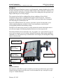
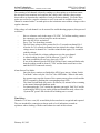
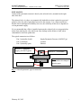
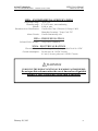
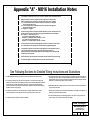
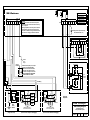
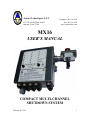
Axiom Technologies L.L.C
15711 W. Hardy Road, Suite 1
Houston, Texas 77060
Telephone: 281 931 0907
Fax: 281 231 6562
www.axiomsafety.com
MX16
USER’S MANUAL
COMPACT MULTI-CHANNEL
SHUTDOWN SYSTEM
February 20, 2015
1
Axiom Technologies
15711 W. Hardy Road, Suite 1, Houston, Texas 77060
MX16 User’s Manual
Phone 281 931 0907
GENERAL
The MX16 alarm and shutdown system is a self supported, compact shutdown device that
has been designed to provide a safe and reliable means to detect abnormal conditions on a
production process and initiate a shutdown if any of the reading show the operation is no
longer within the pre-set safety margins.
The system has been built to withstand the adverse conditions of the oil-field
environment and provides a straightforward interface with the operator. Abnormal
conditions are indicated by indicator lamps (LEDs), each associated with a front panel
label indicating the condition detected.
Powered by lithium batteries, the system is expected to operate for about three years
without replacing batteries, and there is little or no maintenance needed besides
recommended periodical functionality testing.
The MX16 can connect up to sixteen (16) loop monitored external alarm inputs and six
(6) solid state outputs for indicating shutdown and service alerts respectively.
The alarms channels can be connected to any “dry contact” (or “open collector”) type of
sensor such as pressure or level switches, manual ESD stations, and telemetry shutdown
commands, etc. Each remote loop is monitored for wire integrity for insuring that wiring
faults are also detected.
Indicator LEDs
“End Test” –
“Test” Switch
“Reset/Open” –
“Close” Switch
Solenoid Valve
Field Wiring
Entrances
Fig. 1 MX16 General Layout
INSTALLATION
The enclosure of the MX16 is made of stainless steel and is provided with a pair of Strut
Channels located on the back of the unit; it can be mounted on any vertical pole or pipe
of up to 6” Outside Diameter.
February 20, 2015
2
Axiom Technologies
15711 W. Hardy Road, Suite 1, Houston, Texas 77060
MX16 User’s Manual
Phone 281 931 0907
THE MX16 ENCLOSURE IS TO BE MOUNTED
UPRIGHT IN THE VERTICAL POSITION ONLY.
BATTERY PACK INSTALLATION AND ACTIVATION
Typically, the MX16 is shipped with the battery module installed in the “storage
position” for shipment. To insure correct operation of the MX16 proceed as follows:
1. Remove the four nylon nuts holding the battery module, rotate the module 180º
and carefully re-install as shown below (see Fig. 2).
2. Press and release the “Initialize” switch located in the upper left corner of the
main board. The MX16 responds by testing all the LEDs and then blinks the
System OK green LED every second. The MX16 is not yet ready to operate,
and it will not respond if an alarm would be detected.
Confirm that the well is either locked open or
manually closed to prevent unintended operation
before proceeding with the next steps.
3. Press “Reset/Open” on the right toggle switch located on the front. The MX16
responds with a fast flashing of the “System OK” green LED followed by the
normal flashing of once per second. Now the MX16 is ready to assume safety
monitoring operation.
Initialize Switch
Battery Pack in
“Shipping” position,
Battery Pack “In
Service”
Fig. 2 Battery Pack installation
THE BATTERY PACK IS TO BE REPLACED ONLY WITH AXIOM
BATTERY MODULE PART NO. AT00000001
February 20, 2015
3
Axiom Technologies
MX16 User’s Manual
15711 W. Hardy Road, Suite 1, Houston, Texas 77060
Phone 281 931 0907
⚠
ELECTRONIC SYSTEM
The electronic circuits, sixteen (16) alarm inputs and six (6) outputs, are shown in
Appendix “A” – MX16 Installation Notes, Drawing No. AT-MX16-I.
⚠WARNING – EXPLOSION HAZARD
•
SUBSTITUTION OF COMPONENTS MAY IMPAIR SUITABILITY
FOR CLASS 1, DIVISION 2
•
DO NOT DISCONNECT EQUIPMENT OR REPLACE COMPONENTS
UNLESS THE AREA IS KNOWN TO BE NON-HAZARDOUS
•
PROTECTION MAY BE IMPAIRED IF THIS DEVICE IS USED IN AN
APPLICATION OR MANNER NOT SPECIFIED IN THIS MANUAL
The bottom of the enclosure has a total of ten (10) ½” NPT female fittings, where
compatible cable glands or conduits may be connected for field wiring.
FIELD WIRING
For reliable operation, the wire used for connecting to the alarm switches, must retain
reasonably good insulation resistance values. Severe wiring decay can be avoided by
selecting the proper type of cable. If the cable is to be buried, then selecting a cable that
will maintain a reasonable level of insulation resistance is critical.
Given the low currents involved with the alarm signals, the wiring selected can be as thin
as #30 AWG and still operate satisfactorily at distances of over 3,000 FT. One of the
best means for wiring the field sensors is to use direct burial telephone cable.
If the wire is to be run in conduits, then it must be verified that the wire insulation will
not decay when wet, as water tends to accumulate in conduits, especially if run
underground. If the insulation resistance would severely decay and fall below 100
KOhm, then the system may be unable to recognize conditions of open circuits (wiring
failure) in the loop.
If the wiring is to be spliced, then the splicing is to be made in a junction box above
ground or the proper repair kit is to be used for insuring the insulation’s integrity.
February 20, 2015
4
Axiom Technologies
MX16 User’s Manual
15711 W. Hardy Road, Suite 1, Houston, Texas 77060
Phone 281 931 0907
The MX16 operates with “Normally Open” circuits as normal condition. For monitoring
wiring integrity, an “End Of line Zener” is connected in parallel with the corresponding
alarm switch. It is to be noted that the current for the inputs is well below incendive
levels and the highest current any given input can produce is 20 mA at a theoretical
16.8vdc.
The EOZs are shipped connected within the enclosure. When connecting an alarm to the
MX16, the EOZ is to be moved from the box and connected in parallel with the alarm
switch.
For example, if a “Water Tank High Level” alarm is to be connected to channel No. 1,
then the end of line Zener at terminal TB1, position 1 (Labeled as IN1) is to be connected
to the pair of wires (“Signal” and “Common”) running up to the tank. Then the EOZ is to
be connected in parallel with the level switch at the water tank.
Assuming that a direct burial telephone cable is being used, it has a white wire as one
conductor in each pair. It is common practice to parallel all white conductors in such a
way that any white wire would provide the needed “common” point to the sensor being
connected. At the MX16 enclosure, multiple white wires can be crimped together in a
single ring lug and then the ring lug mounted on the “Common” stud.
If junction boxes are used, the same practice of connecting all white wires together offers
a great simplification, as it eliminates the need to carefully select the correct white wire
for any given alarm switch.
By observing the alarm LEDs on the front panel of the MX16, the installer can determine
if a given alarm sensor has been correctly connected. For example, if the wiring to the
alarm switch connected to channel No. 3 has not been properly connected, then the LED
associated with channel No. 3 will remain double-blinking and the MX16 would not
respond to the command for opening the SSV.
On the other hand, if there is a short circuit on the loop to channel No. 3 or the EOZ has
been connected backwards, then Channel No. 3 will remain in alarm (single blinking).
The opening of the SSV would be allowed but for only a limited amount of time, as the
MX16 will shutdown if the existing alarm does not clear within thirty minutes.
The system monitoring of the alarm wiring operates by reading the voltage on each of the
alarm channels and responding as follows:
0.0 through 3.0 VDC
3.1 through 6.0 VDC
6.1 through 8.0 VDC
8.1 VDC and above
February 20, 2015
Alarm
Wiring warning. The MX16 blinks the “Service Needed”
LED but does not initiate shutdown. This condition may
indicate a serious decay on the wiring’s insulation.
Normal, no alarm
Wiring Failure (Open circuit)
5
Axiom Technologies
15711 W. Hardy Road, Suite 1, Houston, Texas 77060
MX16 User’s Manual
Phone 281 931 0907
The scanning of all channels is done by sending very short pulses to each alarm sensor;
the microprocessor monitors and compares the voltage value with the voltage ranges
shown above to determine the condition of each given alarm channel. Given the above,
pulses are too fast for a regular voltmeter to read; a test mode is available where each
channel is scanned with a 5 seconds pulse so the technician can read these voltages with a
regular voltmeter.
If the voltage of each channel is to be metered for troubleshooting purposes, then proceed
as follows:
-
-
Have a voltmeter ready in the range of 12 VDC. To facilitate reading, connect
the common to any convenient place on the enclosure.
Have the MX16 box un-latched.
Press “Test” for about three seconds.
The field loop voltage will be present for five (5) seconds on channel No.1.
After the five (5) seconds on channel one has expired, the voltage field loop
voltage moves to channel No. 2 and the technician has again, five seconds to
read the voltage.
Every five seconds, the voltage reading moves to the next channel.
A normal reading (no alarm) will be between 7.0 and 7.6 VDC.
An alarm condition will read very close to 0.0 VDC.
If one of the channels has the EOZ (End Of line Zener) connected backwards,
then the reading would be about 0.5 VDC and the alarm would never clear
until the EOZ is connected correctly.
Alarm Sensor Test Mode.
Once the above routines are finished the MX16 goes into an “Alarm Switch
Test Mode” where only the “On Test” blue LED blinks. When in this mode,
the operator can cause the closure of the contacts on any alarm switch and the
MX16 responds by flashing the corresponding alarm LED.
The Alarm Switch Mode stays active for fifteen (15) minutes before returning
to the normal alarm and shutdown mode.
For interrupting the “Test” routine the operator can toggle “End Test” and for
confirming the MX16 is now on the Alarm and Shutdown mode, observe the
“System OK” green LED which will be blinking once a second.
Time Delays
Channels 13-16 have a ten (10) second delay before an alarm is recognized and reported.
They are intended for connection to alarms such as level indications on tanks or
separators where sloshing of fluids would otherwise result in false alarms.
February 20, 2015
6
Axiom Technologies
MX16 User’s Manual
15711 W. Hardy Road, Suite 1, Houston, Texas 77060
Phone 281 931 0907
PNEUMATICS
Control of the pneumatic actuator is done by the solenoid valve, mounted on the right
side of the box.
The solenoid valve is a three way magnetically latched device that is pulsed to open and
pulsed to close the path of pneumatic pressure to the actuator. It is a time tested device
that has shown unsurpassed reliability, however, the reliability of this device depends on
a clean pneumatic supply.
It is recommended that a filter is installed upstream the solenoid valve to stop particulate
matter from entering the valve which can cause leakage and/or failure to latch, when
commanded to reassume production.
The typical connection is as follows:
Port 1 (normally closed)
Port 2 (common)
Port 3 (normally open)
Port No. 1 - Pneumatic
Supply (100 PSI Typical)
Supply Pneumatic Pressure (100 PSI Typ.)
Actuator
Exhaust
2
Port No. 3 - Exhaust
Port No. 2 - To Actuator.
Note:
Port numbers are stamped
near the ports
Fig. 4 Solenoid pneumatic typical connection
February 20, 2015
7
Axiom Technologies
MX16 User’s Manual
15711 W. Hardy Road, Suite 1, Houston, Texas 77060
Phone 281 931 0907
MX16 - ENVIRONMENTAL SPECIFICATIONS
Temperature range
Humidity range
Altitude
Hazardous Area Classification
:
:
:
:
-40 to +85C
0 To 95% max., non-condensing
4,000 m. max.
Certified for Class I, Division 2, Groups C & D,
Hazardous Locations. Temp. Code T3C
Alarm Circuits : Certified intrinsically safe
MX16 - PRESSURE RATINGS
Solenoid Valve Pressure : 100 psi max. (standard),
MX16 - ELECTRICAL RATINGS
Electrical Source : Dual voltage lithium battery module3.6 & 14.4 VDC
Current consumption : 20 mA max. on 3.6VDC Circuits
0.5 mA (3 A max. pulse) on 14.4VDC Circuits
⚠WARNING!
TO REDUCE THE RISK OF IGNITION OF HAZARDOUS ATMOSPHERES:
Do not open this enclosure unless the area is known free of ignitable
mixture of gases. Keep tightly closed when in operation.
February 20, 2015
8
Appendix "A" - MX16 Installation Notes
1
This apparatus is suitable for use in a Class 1, Division 2, Groups C & D or unclassified locations.
2
Entity parameters for field wiring to permit selection of appratus for interconnection:
Vmax = 16.8 Volts DC, Imax = 20 mA on 3.6 Volt DC Circuits and Po max = 1.84 Watts
La = 100.0 mH (maximum value of inductance that can be connected to the apparatus
intrinisically safe input circuit.)
Ca = 12.6 uF (maximum value of capacitance that can be connected to the apparatus
intrinisically safe input circuit.)
Ci= negligible, Li = negligible
3
Use the following formulas to calculate the allowed capacitance (Ca') and inductance values (La')
for field wiring used in the non-incendive field wiring circuit (Belden 8451 use for Example*):
Note: symbol " < " means less than (3 < 7)
Ca' = C pF/ft X length of wiring loop (ft) < Ca
Example*: Ca' = 33.45 pF/ft X 800 ft = 0.0268 uF < 12.6 uF
La' = L uH/ft X length of wiring loop (ft) < La
Example*: La' = 0.17uH/ft X 800 ft = 136.0 uH < 100.0 mH
4
The associated non-incendive field wiring apparatus shall not be connected in parallel unless
this is permitted by the the associated non-incendive field wiring apparatus approval.
5
This apparatus is approved for connection to simple apparatus, two wire applications such as
"dry" contacts, transistor open collector that would "pull signal to ground", etc.
Polarity requirements: TB1 and TB2-Input SIG are positive voltage (3.6 VDC); TB3-Input COM
are return or ground connection.
6
Intrinsically Safe (IS) type loop monitored alarm inputs must be isolated from any non-IS wiring.
7
The solid stste outputs for shutdown and service alerts are rated non-incendive.
See Following Sections for Detailed Wiring Instructions and Illustrations
1- The MX16 operates with normally open contacts, a contact closure indicates that an alarm is present.
2- For supervising field wiring, each input channel is provided with a 7.5V "End Of line Zener" (EOZ) at the
MX16's input terminals. At the time of installation, the EOZ is to be removed from the MX16 and re-installed at
the end of the loop, connected in parallel with the alarm switch. If more than one alarm switch is daisychained, then the EOZ is to be installed at the very last switch. The EOZ at the end of the alarm wiring allows
the MX16 to confirm the wiring's integrity.
5- Each input sends a pulse of about 11VDC to the alarm switch. If the EOZ is connected (as it should), then
the voltage is cut down to 7.3VDC (+/- 0.3VDC) and the MX16 accepts this voltage as a normal condition. If
the EOZ would be missing or the wiring to the alarm switch disconnected, then the voltage may rise above
8VDC which is considered a "Wiring Failure" and cause shutdown.
6- Multiple MX16s, MI6s, XP7s and XH5s may share a single alarm switch such as a tank level, ESD station or
any "dry contact" alarm switch.
3- The EOZ must be connected in the correct polarity, Blue wire to "Signal" and White wire to "Common".
Connecting the EOZ on a reverse polarity will cause the corresponding channel to stay on alarm.
7- The alarm output of an MX16 can be used as input for another MX16, or an XH5, MI6 or XP7. Make sure the
EOZ is properly connected for wiring supervision.
4- The alarm switch may be located up to 3,000FT from the MX16
8- For reading field wiring voltage, push and hold toggle switch on "Test" for two or three seconds for the
system to go into a "Test" cycle as described on the User's Manual.
Axiom Technologies
MX16 Wiring Diagram
Monitored Inputs for
Safety Shutdown System
Reference:
Sheet:
AT-MX16-I
1 of 2
Rev:
2
Date:
2/18/2015
MX16 Enclosure
TB2
3
4
5
Common
NOTES:
- All unused channels must have their respective
End Of Line Zener connected as sent from factory
for it to operate.
- Missing any EOZ will cause the system to alarm on
"Wiring Failure" and prevent well from opening.
- A resistor of 15KOhm, no larger than 20 Kohm can
be used as an emergency substitute of the EOZ.
16
TB4
1
2
Outputs
3
4
5
6
7
8
EOZ (Required for supervised loops XP7, MI6, MX16, XH5, etc.)
Signal Inputs
2
3
Common
4
1
2
3
Blue
COMMON
XP7 (Example Only)
Blue Wire
goes to
"Signal"
1
White Wire
"Common"
2
4
White
Blue
Blue
1
White
2
White
1
9 - 16
Blue
Alarm "Signal" 01 - 8
White
TB1
Output Function
3 - Shutdown
4 - Service Needed
5 - Alarm on Ch. 1-4
6 - Alarm on Ch. 5-8
7 - Alarm on Ch. 9-12
8 - Alarm on Ch. 13-16
Service Needed
End-Of-line Zener (EOZ) on each input
Typical of 16 supplied with MX16
EOZ must be removed and installed
with remote alarm switch as shown
on channels 1 through 5 of this sheet
MUST BE CONNECTED FOR WIRING
FAILURE ALARM TO GO AWAY!
3
4
5
+ 12 or
6
-
7
24 VDC
source
Field Wiring
8
Shutdown
Red
Blue
blue
Black
EOZ
Control panel, external to the MX16 (Example Only)
Black
Polarity IS
Important!
COM.
White
(High Tank Level)
Blue
LOW
white
High
Level
Switch
Red
HIGH
GRD.
EOZ (End Of line Zener)
To be connected as shown
(Hi-Lo Pressure "Square" Switchgage)
White
Wire Nuts
EOZ (End Of line Zener)
To be connected as shown
(Hi-Lo Pressure "Round" Switchgage)
Axiom Technologies
MX16 Wiring Diagram
Monitored Inputs for
Safety Shutdown System
Reference:
Sheet:
AT-MX16-I
2 of 2
Rev:
2
Date:
2/18/2015