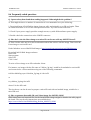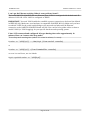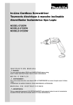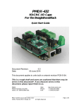
1
AM3352-SOM System-on-Module Linux-enabled board USER’S MANUAL Document revision B, September 2015 Designed by OLIMEX Ltd, 2015 All boards produced by Olimex LTD are ROHS compliant OLIMEX© 2015 AM3352-SOM user's manual DISCLAIMER © 2015 Olimex Ltd. Olimex®, logo and combinations thereof, are registered trademarks of Olimex Ltd. Other product names may be trademarks of others and the rights belong to their respective owners. The information in this document is provided in connection with Olimex products. No license, express or implied or otherwise, to any intellectual property right is granted by this document or in connection with the sale of Olimex products. The hardware design of AM3352-SOM development board is considered intellectual property to Olimex. Hardware schematics are shared with the customers. However, the board layout files are considered copyright material and would not be shared. The hardware design of AM3352-SOM-EVB development board is considered open source hardware. The source design files are published online and accessible by everyone. The software is released under GPL. It is possible that the pictures in this manual differ from the latest revision of the board. The product described in this document is subject to continuous development and improvements. All particulars of the product and its use contained in this document are given by OLIMEX in good faith. However all warranties implied or expressed including but not limited to implied warranties of merchantability or fitness for purpose are excluded. This document is intended only to assist the reader in the use of the product. OLIMEX Ltd. shall not be liable for any loss or damage arising from the use of any information in this document or any error or omission in such information or any incorrect use of the product. This evaluation board/kit is intended for use for engineering development, demonstration, or evaluation purposes only and is not considered by OLIMEX to be a finished end-product fit for general consumer use. Persons handling the product must have electronics training and observe good engineering practice standards. As such, the goods being provided are not intended to be complete in terms of required design-, marketing-, and/or manufacturing-related protective considerations, including product safety and environmental measures typically found in end products that incorporate such semiconductor components or circuit boards. Olimex currently deals with a variety of customers for products, and therefore our arrangement with the user is not exclusive. Olimex assumes no liability for applications assistance, customer product design, software performance, or infringement of patents or services described herein. THERE IS NO WARRANTY FOR THE DESIGN MATERIALS AND THE COMPONENTS USED TO CREATE AM3352-SOM AND AM3352-SOM-EVB. THEY ARE CONSIDERED SUITABLE ONLY FOR AM3352-SOM AND AM3352-SOM-EVB, RESPECTIVELY. Page 2 of 36 OLIMEX© 2015 AM3352-SOM user's manual Table of Contents DISCLAIMER............................................................................................................. 2 CHAPTER 1: OVERVIEW........................................................................................5 1. Introduction to the chapter.......................................................................................................5 1.1 Introduction to SOM (System-On-a-Module).......................................................................5 1.2 Target market of the board.....................................................................................................6 1.3 Features of AM3352-SOM...................................................................................................... 6 1.4 Board variants..........................................................................................................................7 1.5 Board versions used in the manual........................................................................................ 7 1.6 Document organization........................................................................................................... 7 CHAPTER 2: BOARD DESCRIPTION................................................................... 8 2. Introduction to the chapter.......................................................................................................8 2.1 Layout (top view).....................................................................................................................8 2.2 Layout (bottom view)...............................................................................................................9 CHAPTER 3: SETTING UP THE AM3352-SOM BOARD..................................10 3. Introduction to the chapter.....................................................................................................10 3.1 Electrostatic and electrical polarity warnings.....................................................................10 3.2 Requirements..........................................................................................................................11 3.3 Powering the board................................................................................................................12 3.3.1 Stand-alone powering...................................................................................................................................12 3.3.2 Mounted powering....................................................................................................................................... 13 3.4 Button functions.....................................................................................................................13 3.5 Interacting with the board....................................................................................................14 3.6 Expanding the Debian file system space..............................................................................15 3.7 Changing the default image resolution................................................................................15 3.8 Connecting and calibrating a display...................................................................................16 3.9 Software support....................................................................................................................17 CHAPTER 4: THE AM3352 PROCESSOR...........................................................18 4. Introduction to the chapter.....................................................................................................18 4.1 The processor......................................................................................................................... 18 4.2 Block diagram........................................................................................................................ 19 CHAPTER 5: CONTROL CIRCUITY................................................................... 20 5. Introduction to the chapter.....................................................................................................20 5.1 Reset........................................................................................................................................20 5.2 Clocks......................................................................................................................................20 5.3 Power supply circuit.............................................................................................................. 20 CHAPTER 6: CONNECTORS AND PINOUT......................................................21 6. Introduction to the chapter.....................................................................................................21 6.1 Communication with AM3352-SOM in Linux....................................................................21 6.2 UART0 header....................................................................................................................... 21 6.3 MicroSD card connector....................................................................................................... 22 Page 3 of 36 OLIMEX© 2015 AM3352-SOM user's manual 6.3.1 SD/MMC slot................................................................................................................................................23 6.5 GPIO connectors....................................................................................................................24 6.5.1 AM_CON-GPIO1 (General Purpose Input/Output) 40pin connector....................................................25 6.5.2 AM_CON-GPIO2 (General Purpose Input/Output) 40pin connector....................................................26 6.5.3 AM_CON-GPIO3 (General Purpose Input/Output) 40pin connector....................................................27 6.6 AM_CON-LCD 40pin connector..........................................................................................28 6.7 Jumper description................................................................................................................29 6.8 Additional hardware components........................................................................................ 29 CHAPTER 7: SCHEMATICS..................................................................................31 7. Introduction to the chapter.....................................................................................................31 7.1 Eagle schematic......................................................................................................................31 7.2 General physical dimensions.................................................................................................31 CHAPTER 8: REVISION HISTORY AND SUPPORT........................................ 32 8. Introduction to the chapter.....................................................................................................32 8.1 Document revision................................................................................................................. 32 8.2 Board revision........................................................................................................................ 32 8.3 Useful web links..................................................................................................................... 32 8.4 How to purchase?...................................................................................................................33 8.5 Order codes.............................................................................................................................33 8.6 Frequently asked questions...................................................................................................34 8.7 Product support..................................................................................................................... 36 Page 4 of 36 OLIMEX© 2015 AM3352-SOM user's manual CHAPTER 1: OVERVIEW 1. Introduction to the chapter Thank you for choosing this single board computer from Olimex! This document provides a user’s guide for the AM3352-SOM board. As an overview, this chapter gives the scope of this document and lists the board’s features. The document’s organization is then detailed. The AM3352-SOM development board enables code development of applications running on the AM3352 microcontroller, manufactured by Texas Instruments from the U.S.A. The AM3352-SOM board is typically used together with AM3352-SOM-EVB board which features most of the peripherals and connectors needed for full evaluation and utilization of the AM3352 processor. The hardware design of AM3352-SOM development board is considered intellectual property to Olimex. The hardware layout design files are considered copyright material and would not be distributed. The original schematics, however, are distributed in a popular file format. AM3352-SOM-EVB board is an open-source, open-hardware project and all documentation used to manufacture the board is available to the customer. The software support for both boards is open-source and released under GPL license. 1.1 Introduction to SOM (System-On-a-Module) OLIMEX System-on-Module (SOM) boards are powerful Linux-capable boards. They follow a low-cost modular design which allows rapid product development. Each of these boards has two parts – a main part which nests the processor, the memory and the power control unit and the peripheral part which contains the USB ports, the video output and most of the connectors. SOM designs are targeted at customers who want to apply custom modifications and own solutions based on a specific processor without having to deal with multi layer PCBs with controlled impedance and BGA assembly. This makes it possible to create simple boards (that might be manufactured by your local board manufacturer) containing only the peripherals you need with the dimensions and shape suitable for your specific solution. Both the main part and the peripheral part of the SOM system have support in the official Android and Debian images distributed by Olimex and maintained by Olimex and the Linux community. These images are typically available at the wiki articles of the boards. The peripheral part of the SOM design is considered Open Source HardWare (OSHW) and the customer has access to the board source files that we used to manufacture it. The part of the design that has the main microcontroller is considered proprietary design and design files would not be shared. If you are looking for open source design of the processors used please check the OLinuXino boards. OLinuXino board designs are fully open source but harder to implement in own solutions and require more of a hardware experience to do so. Nevertheless, OLinuXino boards are pretty good choice for evaluating the capabilities of the embedded processors. Page 5 of 36 OLIMEX© 2015 AM3352-SOM user's manual 1.2 Target market of the board Using the AM3352-SOM as a stand-alone development board would be more suitable for users with some hardware experience or people already familiar with other single-board Linux boards and designs. As mentioned in the previous chapter the board is meant to be implemented in a hardware design. It is highly recommended to use AM3352-SOM with AM3352-SOM-EVB initially, unless you have previous experience with SOM or OLinuXino boards manufactured by OLIMEX. Note that in the OLIMEX web-shop the product named “AM3352-SOM-EVB” includes the main board named “AM3352-SOM”. The board's target market widens drastically when AM3352-SOM is used altogether with AM3352SOM-EVB. In that case – the combination is suitable for embedded programming enthusiasts, Linux gadget fans and also professionals (since its low cost makes it very good solution for application-orientated embedded systems). The reason for this alteration is the additional hardware that AM3352-SOM-EVB – it provides direct VGA output and easier ways to connect peripherals to the board. Generally, the processor's resources become easier to access. In which cases a stand-alone AM3352-SOM (without AM3352-SOM-EVB) board might not be suitable for you: 1. If you are a beginner with single-board Linux computers 2. If you are an OSHW purist 3. If you are looking for more straight-forward software development and you are not going to implement the AM3352-SOM in own hardware products In the cases above, it might be a better idea to take a look at the OLinuXino boards (like A20OLinuXino-MICRO or A20-OLiuXino-LIME2). 1.3 Features of AM3352-SOM The AM3352-SOM board has the following set of features: • • • • • • • • • • • Texas Instruments AM3352 Cortex-A8 processor running at 1GHz 512MB DDR3 memory Power supply DCDC MicroSD card connector UART console User LED Power LED NMI button Reset button 4 connectors × 40 pin @ 0.05" step Dimensions of the SOM part: (2.4×1.5)'' ~ (61×38)mm Page 6 of 36 OLIMEX© 2015 AM3352-SOM user's manual 1.4 Board variants At the time of writing this document, AM3352-SOM is the only Olimex-made board featuring Texas Instruments AM3352. Other SOM boards that might be compared to functionality are: the well-supported A20-SOM, and the new powerhouse RK3188-SOM. Another Olimex board with close characteristics is A13-SOM board. The performance of Texas Instrument’s AM3352 and Allwinner's A13 is nearly identical. The two main differences are: the A13 is cheaper; the AM3352 is documented much better. Another important point is that we consider the A13 boards mature – many of the issues had already been resolved and the performance is stable. For simpler command-line tasks A13-SOM might be the most suitable choice. 1.5 Board versions used in the manual The documents follows the hardware layout of AM3352-SOM board revision C. AM3352-SOM-EVB revision D peripheral board was used while writing this document. Different board revisions might have different features or settings. It is possible that parts of this document do not apply to all board revisions. 1.6 Document organization Each section in this document covers a separate topic, organized as follows: – Chapter 1 is an overview of the board usage and features – Chapter 2 contains the general board diagram and layout – Chapter 3 provides a guide for quickly setting up the board and software notes – Chapter 4 describes the component that is the heart of the board: the Texas Instruments' AM3352 processor – Chapter 5 is an explanation of the control circuitry associated with the processor – Chapter 6 covers the connector pinout, peripherals and jumper description – Chapter 7 provides the schematics and the dimensions of the board – Chapter 8 contains the revision history, useful links and support information Page 7 of 36 OLIMEX© 2015 AM3352-SOM user's manual CHAPTER 2: BOARD DESCRIPTION 2. Introduction to the chapter Here you get acquainted with the main parts of the board. Note the names used on the board might differ from the names used below to describe them. For the actual names check the AM3352-SOM board itself. 2.1 Layout (top view) The picture below shows the top side of the board and highlights the most important parts: The four plastic connectors (AM_CON-LCD; AM_CON-GPIO1; AM_CON-GPIO2; AM_CONGPIO3) have 0.05'' step between the pinholes. These connectors are typically used to connect to AM3352-SOM-EVB. The pins of the UART0 header consist are suitable for powering the board (+5V and GND); and also for serial connection (TX, RX, GND). Page 8 of 36 OLIMEX© 2015 AM3352-SOM user's manual 2.2 Layout (bottom view) The picture below shows the bottom side of the board and highlights the most important parts: The power LED indicates whether the board is powered properly. It is not connected to a processor pin. The user LED is connected to processor ball B12 and can be programmed. Page 9 of 36 OLIMEX© 2015 AM3352-SOM user's manual CHAPTER 3: SETTING UP THE AM3352-SOM BOARD 3. Introduction to the chapter This section helps you set up the SOM development board for the first time. Please consider the electrostatic warning to avoid damaging the board, then discover the hardware and software required to operate the board. The procedure to power up the board is given, and a description of the default board behavior is detailed. 3.1 Electrostatic and electrical polarity warnings AM3352-SOM boards are shipped in a protective anti-static package. The board must not be exposed to high electrostatic potentials. A grounding strap or similar protective device should be worn when handling the board. Avoid touching the component pins or any other metallic element. Ensure that your development board gets attached to properly working hardware. If this is not possible please use isolators (like USB-ISO) to save your development board from potential over voltage. If you connect other electrical devices to the SOM board make sure that they have equal electrical polarity. For example, when you connect a serial cable connected between a PC and the board's DEBUG port it is a good idea to have them both connected to the same electrical source (to the same utility power socket). In rare cases different polarity might cause hardware damage to the board. Page 10 of 36 OLIMEX© 2015 AM3352-SOM user's manual 3.2 Requirements In order to set up the AM3352-SOM board optimally one or more additional items may be needed. These might be generally placed in two categories: Required – items that are needed in order to achieve minimum functionality; Recommended – items that is good to have in order to be able to interact with the most important of the features of the board; Note that if AM3352-SOM is mounted on AM3352-SOM-EVB – the requirements would be different! The requirements below are for a stand-alone use of AM3352-SOM. Refer to AM3352SOM-EVB's user's manual for adjusted requirements. Required items: - 5V-external power supply with proper connectors – AM3352-SOM has no power jack, neither battery connector, neither USB port; power has to be provided to the suitable pins (+5V, GND) - Output device – USB-SERIAL-CABLE-F + personal computer with serial terminal program – AM3352-SOM lacks other options for debugging – you would need a serial cable suitable for the 3.3V UART signals - SD card with compatible image – official images are available at the wiki article for the board. Recommended items: - AM3352-SOM-EVB – reference design of a 2-layer board for AM3352-SOM that adds video and display output and connectors, 2×100MB Ethernet with connectors, CAN driver with connector, USB-OTG, JTAG connector, 4×USB HS/FS/LS hosts. The AM3352-SOM-EVB board also adapts the 0.05'' step GPIO headers of the AM3352 to 0.1'' step headers so you can easily access the available signals. It has an open source hardware design and the design files are available as Eagle CAD files. This eases the process of creating custom shields with custom peripherals. Some of the above-suggested items can be purchased by Olimex, for instance: USB-SERIAL-CABLE-F – female USB serial console cable – provides the easiest way of debugging AM3352-DEBIAN-SD – a tested, class 10 micro SD card suitable for AM3352-SOM with the latest (by the time of leaving Olimex facilities) official Debian Linux release Page 11 of 36 OLIMEX© 2015 AM3352-SOM user's manual 3.3 Powering the board The powering requirements of the AM3352-SOM are different depending on whether you use it in stand-alone mode or mounted atop AM3352-SOM-EVB. The sub-chapters below deal with both scenarios. 3.3.1 Stand-alone powering If you use the board in stand-alone mode (e.g. it is neither attached to AM3352-SOM-EVB nor to any other board of peripherals) there are fewer options for powering it. Consider that you might need additional cables or connectors. You have the following options of powering the board: 1. provide +5V DC voltage to pin “+5V” at the UART0 header; connect ground to pin “GND” of the same header 2. provide +5V DC voltage to pin 1 and GND to pin 2 of any of the following headers – AM_CONLCD header; AM_CON-GPIO1; AM_CON-GPIO2; AM_CON-GPIO3. IMPORTANT – provide power supply to only one of the mentioned pins, providing 5V to more than one header simultaneously would lead to over-voltage! The default way of powering the board is using external power supply. In that case you would need to provide +5V DC to the “+5V” pin of the UART0 (DEBUG) connector. You would also need to connect the GND line of you supply to one of the GND pins of the same connector. The minimum power that your supply should be able to prove is 2.5W (equivalent of 0.5A of current at 5V of voltage). Note that there is no standard jack for the powering circuit but you might add own DC power jack. Do not provide AC voltage to the AM3352-SOM board! Do not provide more than 5V of voltage directly to the AM3352-SOM board! Providing 12V would instantly cause permanent hardware damage! Page 12 of 36 OLIMEX© 2015 AM3352-SOM user's manual 3.3.2 Mounted powering Typically, AM3352-SOM gets evaluated when mounted atop AM3352-SOM-EVB. In this case the former is powered via the latter. The power line, altogether with a number of other important processor lines, is transferred via the 40-pin headers. AM3352-SOM receives power from AM3352SOM-EVB, but what are the requirements to power AM3352-SOM-EVB? You need to provide 6V to 16V DC voltage to the power jack (named PWR) of AM3352-SOMEVB board. The DC barrel jack has 2.0mm inner pin and 6.3mm hole. More information about the exact component might be found here: https://www.olimex.com/wiki/PWRJACK For the European customers, we also stock and sell basic power supply adapters compatible with the power jack. Do not provide AC voltage to the AM3352-SOM-EVB board! Do not provide more than 16V of voltage to the AM3352-SOM-EVB board! The typical consumption of AM3352-SOM-EVB + AM3352-SOM is around 0.20A @ 10V but might reach peaks up to 0.25A @ 10V during initial boot. These values were measured without anything else connected to the board (e.g. no keyboard, no mouse, no LCD display, etc). The board can NOT be powered by a personal computer using the USB_OTG connector. During operation it is typical for some integrated circuits to appear hotter than others. This is perfectly normal for some electronic components – for instance – the voltage regulators and the main processor. 3.4 Button functions The board comes with two buttons listed bellow: RST – reset button – used for hardware reset of the board – before using it, please refer to the note below NMI – non-masked interrupt button – the button is not used in the default Linux image, however it is required for some distributions It is always recommended to perform a software “turn off” of the board or software “reset”. Then you are free to remove the power supply. If you disconnect the power supply (either the USB or the power jack) before turning off the board you may corrupt your SD card. Page 13 of 36 OLIMEX© 2015 AM3352-SOM user's manual 3.5 Interacting with the board The typical and recommended way of interacting with AM3352-SOM board is via a serial cable connected between the UART0 header and a personal computer. You would probably need a cable suitable for such a connection due to the fact that most personal computers lack a serial port nowadays. Even if you have serial port you should respect the CMOS levels of the board which are incompatible with the TTL levels of your computer. We distribute a ready-to-use plug-and-play cable – it is called USB-SERIAL-CABLE-F. Even if you already have such a cable or you decide to purchase it elsewhere it is advisable to check this product page for a reference: https://www.olimex.com/Products/Components/Cables/USB-Serial-Cable/USB-Serial-Cable-F/ You need to connect the cable to the UART0 pins as follows: RX line to TX pin; TX line to RX pin; GND to GND. Make sure that the serial cable is connected to your personal computer and recognized properly after driver installation. After the hardware connection is established, open a terminal program on the serial (COM) port which the cable is associated with. The typical baud rate is 115200, the rest of the settings should be left as per default. After everything else is set, you would need to power the board as explained in “3.3 Powering the board”. The default username/password combination of the official images is: olimex/olimex. In order to save time you might want to log as super user initially. The reason is that most commands require super user privileges. To log as super user execute “sudo su” and write the password. If AM3352-SOM is attached to AM3352-SOM-EVB, in addition to the serial communication, you might also use one or more of the following mediums to interact with the board: 1. a monitor via the DE-15 VGA connector 2. SSH with a remote computer via one of the Ethernet connectors (LAN1 or LAN2) 3. a compatible display via the LCD connector Refer to the AM3352-SOM-EVB's datasheet for more information on each connection. Note that not all interface options are available for all images. Using VGA, LCD or LAN might require additional configurations. Furthermore, it is possible to corrupt the output settings over those interfaces and, thus, lose the output. In such cases, you can always use the serial cable USB-SERIAL-CABLE-F as a reliable way to establish connection to the board. Page 14 of 36 OLIMEX© 2015 AM3352-SOM user's manual 3.6 Expanding the Debian file system space The provided official Debian images have constant size but you may want to use a bigger microSD card. In case you don't know how to expand the file system space you can use the built-in shell script for this task. This way you can take advantage of the whole volume of your microSD card. Log in as a super user: sudo su Type the password: olimex Then type: resize_sd.sh /dev/mmcblk0 1 After that you need to reboot the board with: reboot You can find the name given to the microSD card and its partitions using: fdisk -l 3.7 Changing the default image resolution To ease the process of changing the video output settings in the default Linux image we have provided a shell script that can be executed. Using it you can set the preferred video output medium and video output resolution. The script requires root privileges. It is very good idea to use a serial cable for connection to the board from a personal computer since in this case you are not dependent on the current video output resolution (a cable like USBSERIAL-CABLE-F). When the board boots type: sudo ./change_display_am3352.sh This would bring up the help information about the usage of the script. You can see that the LCD and VGA resolutions supported. The supported resolutions that you can select are: LCD OUTPUT [-l YxY], where YxY can be: VGA OUTPUT [-v YxY], where YxY can be: 480×272 800×600 800×480 1024×768 1024×600 Page 15 of 36 OLIMEX© 2015 AM3352-SOM user's manual For example, to set LCD video otuput suitable for 7 inch display (800x480) write: sudo ./change_display_am3352.sh -l -800x480 At this point you would be asked if you wish to reboot the board. The video output changes would be applied after a reboot, so it is advised to reboot the board at this point. The usage f the script is shown in the picture below: In case you need a custom video output resolution you would need to edit the kernel. There are no configuration files that can be easily edited to achieve the desired video output. 3.8 Connecting and calibrating a display One of the ways to interact with the board is via an external display (with or without touchscreen component). However, there is only a 40-pin female connector AM_CON-LCD with a 0.05'' step. Unlike other OLIMEX Linux-enabled boards, the AM3352-SOM lacks a row of pins that allows the user to connect a display out-of-the-box. The board's AM_CON-LCD connector is female and has a smaller 0.05'' step (note that if you are using AM3352-SOM mounted on AM3352-SOM-EVB a 0.01'' LCD connector would be available). This means that if you use a stand-alone AM3352-SOM for LCD output and a display made by OLIMEX, you would need additional 2×20 MALE-MALE 0.05'' header to convert the female connector to male. The 0.05'' headers are somehow hard to find so we sell them here: 0.05'' step connectors. You would also need a compatible cable between the board and the display. The current generation of OLIMEX-made displays have both 0.1'' and 0.05'' step connectors. The cable used for connection depends on the specific board you are using and Page 16 of 36 OLIMEX© 2015 AM3352-SOM user's manual more specifically it depends on the pitch of the LCD connector of the board. We have two cables – both 40-pins ones but one for the bigger pitch (0.1'') and the other for the smaller one (0.05''). Each of the displays listed in the table above has two connectors suitable for both cables: CABLE-IDC40-15cm – 15cm long cable suitable for 0.1'' step connectors – Product page CABLE-40-40-10CM – 10cm long cable suitable for 0.05'' step connectors – Product page The displays recommended for the board at the moment of writing might be found in the table below: Display name LCD-OlinuXino-4.3TS LCD-OLinuXino-7 LCD-OLinuXino-10 Size of display in inches 4.3 7 10.1 Native resolution in pixels 480×272 800×480 1024×600 Official Debian image support Link to product page Yes Yes Yes Product page Product page Product page The default Debian image lacks a graphics environment. This is one of the reasons for the lack of touchscreen support. Touchscreen displays are recommended only for experienced embedded Linux users. 3.9 Software support At the moment, we provide ready-to-use Debian Linux images suitable for the micro SD card of the board. We also provide instructions and sources of these releases. These images might be downloaded for free and modified as the user wishes. The latest images and updates are featured at the wiki article of the device: https://www.olimex.com/wiki/AM3352-SOM. We usually try to provide extra details and best experiences with our products at our wordpress page: http://olimex.wordpress.com/. Another useful place is the Olimex forums where a lot of people share their experience and advice: https://www.olimex.com/forum/. The official images are a constant work-in-progress – newer releases are packed with better hardware support, newer kernels and extra features. You are more than welcome to send or share your suggestions and ideas at our e-mail, the public forums or irc channel. We would attempt to help in almost every case. We listen to the feedback and if the majority of users suggest a software change or update we try to implement such. Customer feedback is very important for the overall state of the software support. However, do not expect full Linux software support. We can share our experience. We can give you full details for things we have tried. We can point you to a resource or a guide. We can give you general directions to solving a specific problem or places to look for more information. However, we won’t install a piece of software for you or write custom program for you. We won't provide a specific software solution to a specific software problem. Page 17 of 36 OLIMEX© 2015 AM3352-SOM user's manual CHAPTER 4: THE AM3352 PROCESSOR 4. Introduction to the chapter In this chapter is located the information about the heart of AM3352 – its main processor. The information is a modified version of the datasheet provided by its manufacturers – Texas Instruments. 4.1 The processor The main feature of the AM3352 is the quality manufacturing, the computing power and the very goo documentation. The software support for the features in the processor is at pretty good state thanks to the efforts of the BeagleBone community (the most popular board with AM335x processors) and Texas Instruments themselves. The exact processor that we use is AM3352ZCZD72. When browsing the documentation of the processor refer to the information for the ZCZ ball layout. Of particular importance is that Texas Instruments provides excellent documentation and support for AM3352. A short list of features might be found below: CPU: ARM Cortex-A8 @ 1000 MHz; On-chip L1 cache 64 KB; On-chip L2 cache 256 KB GPU: Graphics accelerator (SGX530) LCD display option 2×USB ports 3×MMC interfaces 6×UART 3×I2C 3×Enhanced high-resolution PWM modules ADC×8-channel 12-bit 2×CAN RTC General-purpose memories supported: 16-bit (GPMC, NAND flash, NOR flash, SRAM) DRAM supported: 16-bit (LPDDR-400, DDR2-532,DDR3-800) More information about the features of the microprocessor can be found in its documentation available at the web site of its manufactuerer – Texas Instruments: http://www.ti.com/lit/ds/symlink/am3357.pdf Please note that not all processor capabilities are properly supported in the official Linux image! Page 18 of 36 OLIMEX© 2015 AM3352-SOM user's manual 4.2 Block diagram The block diagram was taken from the based on the AM3352's documentation. Page 19 of 36 OLIMEX© 2015 AM3352-SOM user's manual CHAPTER 5: CONTROL CIRCUITY 5. Introduction to the chapter Here you can find information about reset circuit and quartz crystals locations, the power supply circuit is also briefly discussed. 5.1 Reset The board has hardware reset is handled by MCP130T-300I/TT – a voltage supervisory device designed to keep a microcontroller in reset until the system voltage has reached the proper level and stabilized. The processor ball responsible for the reset of the board is ball A10 (WARMRSTn). There is a hardware reset button placed on the board. The name of the button is “RST”. It is a good practice to perform software reset of the board. Performing a hardware reset or powercycling the board (reset by disconnecting and re-applying the main power supply) might lead to software corruption of the operating system of choice. 5.2 Clocks RTC clock (32 768Hz) is connected to balls A4 and A6. 24 MHz quartz crystal Q2 is found at balls V11 and V10 of the AM3352 processor. 5.3 Power supply circuit A stand-alone AM3352-SOM consumes around 0.10A when connected to a 5V voltage source (provided at UART0 pins “GND” and “+5V”). During heavy computational tasks the processor consumption might raise up to 0.15A of current (tested at 5V of voltage with 'top d0'). The current consumed might have peaks as high as 0.20A during start-up when different on-board modules are initialized. Make sure your power supply is capable of providing at least 0.5A of current at 5V of voltage (2.5W). For more info on how to power the board refer to chapter “3.3 Powering the board”. Page 20 of 36 OLIMEX© 2015 AM3352-SOM user's manual CHAPTER 6: CONNECTORS AND PINOUT 6. Introduction to the chapter In this chapter are presented the connectors that can be found on the board all together with their pinout and notes about them. Jumpers functions are described. Notes and info on specific peripherals are presented. Notes regarding the interfaces are given. A short summary of the pinout might be found in a separate document here: https://www.olimex.com/Products/SOM/AM3352/AM3352SOM/resources/AM3352_SOM_GPIOs.pdf 6.1 Communication with AM3352-SOM in Linux The direct access method to the Linux command interface is via the serial interface. You would need to use the pins of the UART0 connector (debug connector) and then use your favorite terminal program (puTTy, minicom, picocom, teraterm, etc) to access the command line interface of the Debian the data/send commands. You can use USB-SERIAL-CABLE-F with the UART0 pins – this allows you to establish connection to a personal computer with a free USB port. If you decide to make your own cable you would need to consider that the levels at the board's connector UART0 are in CMOS level (3.3V) and you would need a convertor to bring them to the TTL level of your computer or cable! That is true for the RX and TX also! It is highly recommended to have an USB-SERIAL-CABLE-F (or similar product) at hand when debugging – the video output is not always reliable and if you set wrong display settings you might be unable to recover the settings without a proper UART0connection. For more information please refer to chapter “3.5 Interacting with the board”. 6.2 UART0 header The pins of the UART0 header might be used for serial communication between the board and a personal computer. They can also be used to power the whole AM3352-SOM board. In the case of a video output problem a cable might provide the needed feedback and greatly reduce the efforts needed to repair the board or to adjust the software setting. Note that by default only UART0 is defined as a port suitable for serial debug. You can use our USB-SERIAL-CABLE-F for debugging. AM3352-SOM-EVB provides extra UART0 connector pins suitable for serial connection. These serve the same debug function as the ones on AM3352-SOM. Consider the table on the next page when connecting the USB-SERIAL-CABLE-F to the board. Remember to refer to the wire color code of the cable. The RX line of the cable (GREEN wire) should go to TX line of the target board; the TX line of the cable (RED wire) should go to the RX line of the target board. The BLUE wire should go to a target's GND line. Page 21 of 36 OLIMEX© 2015 AM3352-SOM user's manual The UART0 header can also be used to power a stand-alone AM3352-SOM. This is the recommended way of powering a standalone AM3352 board. The voltage input pin (+) is named “+5V” and it is suitable for 5V DC external power supply unit. One of the two GND pins can be used as ground (-). The required current may vary depending on the peripherals connected to the board. The power supply should be capable of providing at least 2.5W. For the powering, we are only interested in the +5V (+) pin and the GND (-) pin. The signal names are printed near the pins, make sure to inspect the names before connecting the supply. More info about the power supply can be found in chapter 5 of this manual. UART0 Pin # Printed name Signal name AM3352 ball 1 TX P1_11/UART0_TX E16 2 RX P1_10/UART0_RX E15 3 GND GND - 4 GND GND - 5 +5V +5V - 6.3 MicroSD card connector The micro SD card slot is primarily used for booting the operating system. The board works with micro SDHC cards up to 32GB of storage. Note that the speed class rating of the card used affect the performance of the operating system. Higher speed class class rating is better. As a general precaution be careful with the SD cards you purchase. There is a big percentage of fake cards due to the low effort required to counterfeit popular brands and the big demand for SD cards worldwide. When in doubt – try the same operation with another card from another brand. Olimex sells microSD cards with Linux that have been tested – please refer to chapter “3.2 Requirements”. Of course, if you already have a large enough microSD card you can download the official Linux image from the wiki pages: https://www.olimex.com/wiki/AM3352-SOM. When removing the card, please make sure that you release it from the connector by pushing and NOT by pulling the card directly (this can damage both the connector and the microSD card). Page 22 of 36 OLIMEX© 2015 AM3352-SOM user's manual 6.3.1 SD/MMC slot The schematic related to the SD/MMC (microSD connector) is shown below. SD/MMC slot is a microSD card slot connector, located on the bottom of the board. This slot is typically used for booting the OS, due to the larger capacities of the microSD cards (compared to SD or MMC cards). It is suggested to have an SD card with a proper Linux. It is recommended to use class 10 (10MByte/sec) card for faster read/write operations, since lower class cards (especially higher capacity ones) might slow down the whole system. You can find the table with the pinout of the microSD connector on the next page. SD/MMC connector Pin # Connector signal name Wire name (processor ball) 1 DAT2/RES MMC0_DAT2 (F18) 2 CD/DAT3/CS MMC0_DAT3 (F17) 3 CMD/DI MMC0_CMD (G18) 4 VDD SD_VCC (-POWER_CIRCUIT-) 5 CLK/SCLK MMC0_CLKO (G17) 6 VSS GND (-POWER_CIRCUIT-) 7 DAT0/DO MMC0_DAT0 (G16) 8 DAT1/RES MMC0_DAT1 (G15) 9 CARD DETECT(SYMBOL) MMC0_SDCD# (C15) 13 GND GND (-POWER_CIRCUIT-) Page 23 of 36 OLIMEX© 2015 AM3352-SOM user's manual 6.5 GPIO connectors There are 3 GPIO connectors located on the bottom side of AM3352-SOM. They ease the access to processors pins. These connectors (and connector AM_CON-LCD) also provide a way to mount the board to a board of peripherals (like AM3352-SOM-EVB). The only power line at the GPIO connectors that might be used as input is the one named '+5V' available at the first pin of all four connector. The rest of the power signals are outputs and it would be incorrect to try to power the board from there. To keep the form factor as small as possible the GPIO and AM_CON-LCD connectors have 0.05'' step. IMPORTANT: the connectors are very fragile – if you attempt to disconnect the board by pulling only one side out it might break! Furthermore – you might bend the board's pins! Use pliers or other suitable object to disconnect the connectors carefully. OLIMEX sells additional and replacement male and female 0.05'' (50 mil) step connectors. Below you would find tables with the signal at each pin. To understand better what each processor pin does it might be a good idea to refer to the datasheet of the AM3352 processor. The schematic of the board of peripherals AM3352-SOM-EVB might also help you identify the main function of the pins. You can also find the pinout of the GPIO and LCD connectors in a stand-alone document at the following link: https://www.olimex.com/Products/SOM/AM3352/AM3352SOM/resources/AM3352_SOM_GPIOs.pdf Page 24 of 36 OLIMEX© 2015 AM3352-SOM user's manual 6.5.1 AM_CON-GPIO1 (General Purpose Input/Output) 40pin connector AM_CON-GPIO1 connector Pin# Signal name Processor ball Pin# Signal name Processor ball 1 +5V - 2 GND - 3 3.3V - 4 GND - 5 P0_26/LCD_D21 E15 6 P1_31/NDQS V9 7 P1_15/LCD_D16 E16 8 P1_7/NDQ7 T9 9 P2_7/LCD_D1 U6 10 P1_6/NDQ6 R9 11 P2_9/LCD_D3 R7 12 P1_5/NDQ5 V8 13 P0_23/LCD_D22 T6 14 P1_4/NDQ4 U8 15 P2_11/LCD_D5 U9 16 P1_3/NDQ3 T8 17 P2_13/LCD_D7 V6 18 P1_2/NDQ2 R8 19 P2_15/LCD_D9 T7 20 P1_1/NDQ1 V7 21 P0_22/LCD_D23 T17 22 P1_0/NDQ0 U7 23 P1_14/LCD_D17 U18 24 SYS_RESETN A10 25 P0_8/LCD_D12 A15 26 P2_0/LCD_L/R T13 27 P0_10/LCD_D14 V17 28 P2_1/NRB1 V12 29 P2_23/LCD_HSYNC U16 30 P1_16/TXEN R13 31 P2_24/LCD_CLK T16 32 P0_31/NWP/RXERR U17 33 NC* V16 34 P1_20/TXD1 R14 35 P3_19/LCD_PWR_EN T15 36 P1_19/TXD2 T14 37 TPX1 U15 38 P1_18/EHRPWM1A/TXD3 U14 39 TPY1 V15 40 P1_17/RXDV V14 Page 25 of 36 OLIMEX© 2015 AM3352-SOM user's manual 6.5.2 AM_CON-GPIO2 (General Purpose Input/Output) 40pin connector AM_CON-GPIO2 connector Pin# Signal name Processor ball Pin# Signal name Processor ball 1 +5V - 2 GND - 3 3.3V - 4 GND - 5 USB1-VBUS T18 6 USB1_ID P17 7 USB1_DP R17 8 USB1_CE P18 9 USB1_DM R18 10 USB1_DRV F15 11 USB0-VBUS P15 12 USB0-ID P16 13 USB0_DP N17 14 USB0_CE M15 15 USB0_DM N18 16 USB0-DRV F16 17 MMC0-SDCD#/EMU4 C15 18 PMIC_POWER_EN C6 19 PWRONRSTN B15 20 EXT_WAKEUP C5 21 SYS_RESETN A10 22 NNMI B18 23 P0_28/ETXD0 K17 24 P2_21/ERXD0 M16 25 P0_21/ETXD1 K16 26 P2_20/ERXD1 L15 27 P0_17/ETXD2 K15 28 P2_19/ERXD2 L16 29 P0_16/ETXD3 J18 30 P2_18/ERXD3 L17 31 P3_3/ETXEN J16 32 P3_4/ERXDV J17 33 P3_9/ETXCK K18 34 P3_10/ERXCK L18 35 P3_2/ERXERR J15 36 P0_1/EMDC M18 37 P3_0/ECOL H16 38 P0_0/EMDIO M17 39 P3_1/ECRS H17 40 P0_29/EPHY-RST#/RFCLK H18 Page 26 of 36 OLIMEX© 2015 AM3352-SOM user's manual 6.5.3 AM_CON-GPIO3 (General Purpose Input/Output) 40pin connector AM_CON-GPIO3 connector Pin# Signal name Processor ball Pin# Signal name Processor ball 1 +5V - 2 GND - 3 3.3V - 4 GND - 5 P0_15/UART1_TXD D15 6 P0_14/UART1_RXD D16 7 P0_13/I2C2_SCL D17 8 P0_12/I2C2_SDA D18 9 P0_3/SPI0_D0(MISO) B17 10 P0_4/SPI0_D1(MOSI) B16 11 P0_2/SPI0_SCLK A17 12 P0_5/SPI0_CS0 A16 13 P1_9/UART4_TXD E17 14 P1_8/UART4_RXD E18 15 P3_6/I2C0-SCL C16 16 P3_5/I2C0-SDA C17 17 P3_15/SPI1_D0(MISO) B13 18 P3_16/SPI1_D1(MOSI) D12 19 P3_14/SPI1_CLK A13 20 P3_17/SPI1_CS0 C12 21 P3_18/LED1 B12 22 P0_20/EMU3 D14 23 P3_20/LED2 D13 24 P3_21/LED3 A14 25 P3_7/EMU0 C14 26 P3_8/EMU1 B14 27 P0_7/PWM0_OUT C18 28 SYS_RESETN A10 29 JTAG_TCK A12 30 JTAG_TRST B10 31 JTAG_TDI B11 32 JTAG_TMS C11 33 JTAG_TDO A11 34 VREFP B9 35 AIN4 C8 36 AIN7 C9 37 AIN5 B8 38 AIN6 A8 39 VDDA_ADC D8 40 GNDA - Page 27 of 36 OLIMEX© 2015 AM3352-SOM user's manual 6.6 AM_CON-LCD 40pin connector The AM_LCD-CON pins are led out on a separate 40pin connecter for the ease of connecting an LCD. We have tested the ability of the board to interact with such a display. They allow the user to attach additional hardware, check readings or perform hardware debug. Important: you need additional adapter board and two different 40PIN ribbon cables to connect an Olimex display and the LCD_CON. The evaluation board AM3352-SOM-EVB provides a 0.1'' step LCD connector which eases the hardware interfacing between the board and the display. The LCD connector is suitable (but not plug-and-play due to the different pin-step) for a number of Olimex displays and touchscreen panels with different native resolution – the smallest available is the 4.3'' one called LCD-OLinuXino-4.3TS with native screen resolution of 480×272, through the 7'' one named LCD-OlinuXino-7 with 800×480, to the 1024×600 10.1'' LCD-OlinuXino-10. The official Linux image of the board lacks ready touschreen support. Full list of recommended displays for the board might be found in chapter “3.7 Connecting and calibrating a display”. AM_CON-LCD connector Pin # Signal name Processor ball Pin # Signal name Processor ball 1 +5V -POWER CIRCUIT- 2 GND -POWER CIRCUIT- 3 3.3V -POWER CIRCUIT- 4 GND -POWER CIRCUIT- 5 P0_26/LCD_D21 T11 6 P1_13/LCD_D18 R12 7 P1_15/LCD_D16 U13 8 P2_6/LCD_D0 R1 9 P2_7/LCD_D1 R2 10 P2_8/LCD_D2 R3 11 P2_9/LCD_D3 R4 12 P2_10/LCD_D4 T1 13 P0_23/LCD_D22 T10 14 P1_12/LCD_D19 T12 15 P2_11/LCD_D5 T2 16 P2_12/LCD_D6 T3 17 P2_13/LCD_D7 T4 18 P2_14/LCD_D8 U1 19 P2_15/LCD_D9 U2 20 P2_16/LCD_D10 U3 21 P0_22/LCD_D23 U10 22 P0_27/LCD_D20 U12 23 P1_14/LCD_D17 V13 24 P2_17/LCD_D11 U4 25 P0_8/LCD_D12 V2 26 P0_9/LCD_D13 V3 27 P0_10/LCD_D14 V4 28 P0_11/LCD_D15 T5 29 P2_23/LCD_HSYNC R5 30 P2_22/LCD_VSYNC U5 31 P2_24/LCD_CLK V5 32 P2_25/LCD_DE R6 33 NC* - 34 NC* - 35 P3_19/LCD_PWR_EN C13 36 P0_7/PWM0_OUT** C18 37 TPX1 Y22 38 TPX2 AA22 39 TPY1 Y23 40 TPY2 AA23 *Pins 33 and 34 do not reach the processor due to the missing resistors r29 and r32. The values of these pins can be used to change the scanning mode (orientation) of the Olimex displays dynamically. The default scanning mode is “up to down, right to left“. Refer to the display datasheet for possible values. Refer to the display schematic to further trace Page 28 of 36 OLIMEX© 2015 AM3352-SOM user's manual the lcd signals (they can be found on gpio1 pins 2-15 and 2-24). **Pin 36 provides option on which signal would drive the backlight. By default pwm0_out is chosen. The other two options provided are p1_18/ehrpwm1a/txd3 and p3_15/spi1_d0(miso). You would need to remove r38 and place it on the pads of either r36 or r37. Placing r36 would enable p1_18/ehrpwm1a/txd3. Placing r37 would enable p3_15/spi1_d0(MISO). Warning! Re-configuration might brick your device! It is neither needed for typical operation nor recommended. **LCD data pins #0 to #15 are used during initial boot to set the system boot configuration. The default boot priority set by LCD data pins is usb0->nand->spi0->mmc0. Refer to the am3352 documentation for more information about the system boot configuration. 6.7 Jumper description The board has two SMT jumpers. Both are related to the optional NAND memory. These jumpers and their functions are not important for the general use of the board. If you feel insecure of your soldering/cutting technique it is better not to try to adjust the jumper since it is possible to damage the board. Board jumpers Jumper name Type Default position Function By default both jumpers are open. You would need to solder those in order to use the NAND memory pads. NAND_E NWP SMT OPEN Note that you would also need to solder NAND memory and the suitable components of the circuit (marked as NA in the schematic) 6.8 Additional hardware components The components below are mounted on the AM3352-SOM but are not discussed above. They are listed here for completeness: RST button – reset – used to reset the board NMI button – non-masked interrupt – unused PWR_LED – RED power identification LED LED1 – GREEN user-programmable LED 512MB = 4Gb (256 M x 16 bit) DDR3 SDRAM – the exact memory used in the board revision mentioned is SAMSUNG K4B4G1646D-BCK0 The DDR3 memory part name in the schematic might be outdated. We have used a number of different but fully compatible DDR3 memories due to supply unavailability. It is always recommended to check the exact memory name printed on the component itself. There are pads provided for NAND flash memory. The exact memory we had in mind while designing the board might be seen in the latest schematic. You would need to place all Page 29 of 36 OLIMEX© 2015 AM3352-SOM user's manual components missing from the circuit – not only the memory! You would also need to close the NAND_E SMT jumper. Note that we haven't performed any software tests with the NAND memory. Page 30 of 36 OLIMEX© 2015 AM3352-SOM user's manual CHAPTER 7: SCHEMATICS 7. Introduction to the chapter In this chapter is located information about the schematics describing logically and physically AM3352-SOM. 7.1 Eagle schematic AM3352 schematics may be found in the OLIMEX's GitHub repository: https://github.com/OLIMEX/SOM/tree/master/AM3352. You can download the whole repository as .zip without having a GitHub account. The part of the design that has the main microcontroller is considered proprietary design and design files would not be shared. If you are looking for a schematic of an older revision of the board and it isn't available at our web site you may request it by the support e-mail. 7.2 General physical dimensions Note that all dimensions are in mils. Page 31 of 36 OLIMEX© 2015 AM3352-SOM user's manual CHAPTER 8: REVISION HISTORY AND SUPPORT 8. Introduction to the chapter In this chapter you will find the current and the previous version of the document you are reading. Also the web-page for your device is listed. Be sure to check it after a purchase for the latest available updates and examples. 8.1 Document revision Document revision Changes A, 03.06.15 B, 18.09.15 Modified page Initial manual release All Fixed incorrect information about USB026 VBUS being connected to processor ball R15; should be processor ball P15 Improved the picture with the board's dimensions 31 8.2 Board revision Remember to check the schematics and the board design files to compare the differences. Board revision C Notable changes Initial release of the board 8.3 Useful web links The web pages you can visit for more information about AM3352-SOM are: https://www.olimex.com/Products/SOM/AM3352/AM3352-SOM/ Wiki article of the board: https://www.olimex.com/wiki/AM3352-SOM A place for general questions, FAQ or friendly talk: https://www.olimex.com/forum/. You can get the latest hardware updates at the GitHub page: https://github.com/OLIMEX/SOM/tree/master/AM3352. You may may join our IRC channel #olimex @ freenode.net (http://webchat.freenode.net/? channels=olimex). AM3352-SOM-EVB's web page is here: https://www.olimex.com/Products/SOM/AM3352/AM3352-SOM-EVB/. The user's manual of AM3352-SOM-EVB might be found here: Page 32 of 36 OLIMEX© 2015 AM3352-SOM user's manual 8.4 How to purchase? You can purchase directly from our online shop or from any of our distributors. Note that usually it might be faster and cheaper to purchase Olimex products from our distributors. List of confirmed Olimex LTD distributors and resellers: https://www.olimex.com/Distributors. Please visit https://www.olimex.com/ for more info. 8.5 Order codes Short summary of the formal product names of the devices mentioned in this document: AM3352-SOM – the target of this manual AM3352-SOM-EVB – open-hardware reference design on 2 layer PCB that expands A3352-SOM with 4xUSB hosts, USB OTG, CAN driver, VGA, 2x UEXT, JTAG, LCD, 2x100MB Ethernet USB-SERIAL-CABLE-F – USB serial console cable female AM3352-DEBIAN-SD – a tested class 10 micro SD card with the latest (by the time of leaving the Olimex facilities) official Linux release LCD-OLINUXINO-4.3TS – low-cost 4.3'' LCD display with touchscreen component – 480×272 LCD-OLINUXINO-7 – low-cost 7'' LCD display – 800×480 LCD-OLINUXINO-10 – low-cost 10'' LCD display – 1024×600 ALUMINIUM-HEATSINK-20×20×6MM – heatsink radiator for better processor heat dissipation Page 33 of 36 OLIMEX© 2015 AM3352-SOM user's manual 8.6 Frequently asked questions Q: I powered my board and then nothing happened. What might be the problem? A: This might be due to a number of reasons but it is recommended to try the following: 1. Download latest official Debian image from our wiki, and upload it to an SD card again. There are instructions how to do it in the other questions below. Try if the board works now. 2. Check if your power supply provides enough current, try with different/better power supply. 3. Double check the connections at the UART0 connector. Q: How do I write the Linux image to a micro SD card to use with my AM3352 board? A: First visit the wiki article for the board and download the archive with the image. Then write the Linux image to a microSD card. Under Windows we use Win32 Disk Imager: http://sourceforge.net/projects/win32diskimager/ Download Win32 Disk Imager software Insert card Start program Select file Click "write" To write a Linux image to an SD card under Linux: For instance, an image with the file name of "debian_2g.img" would be downloaded to a microSD card connected to a Linux machine using one of the following commands: # dd bs=4M oflag=sync if=debian_2g.img of=/dev/sdX or # cp debian_2g.img /dev/sdX where X is the uSD card. The tips above can also be used to prepare a microSD card with an Android image, suitable for a microSD card. Q: How to generate boot-able SD-card Linux image for AM3352-SOM? Build instructions and required files for the latest Debian images might be found at the wiki page of the board. The step-by-step instructions are available here: https://www.olimex.com/wiki/Building_Debian_AM3352_SOM Page 34 of 36 OLIMEX© 2015 AM3352-SOM user's manual I can't get the Ethernet working. What is wrong with my board? The board AM3352-SOM-EVB has two Ethernet ports. LAN1 is configured with default static IP address of 192.168.1.254. LAN2 is configured as DHCP. IMPORTANT: You need VLAN enabled to establish a proper connection to the board (as defined in IEEE 802.1Q). Make sure your hardware is compatible with IEEE 802.1Q. Make sure you have to enabled VLAN for the router/switch/bridge or the network card otherwise the Ethernet connection to the AM3352-SOM-EVB board will fail. You can find a lot guides online on how to enable VLAN (or VLAN tagging) for your specific hardware and operating system. I have LCD connected and configured. It keeps shutting down after approximately 10 minutes. How can I remove this sleep mode? To set sleep mode entering time (where X is a time in minute; 0 = never): # echo -e '\033[9;X]' > /dev/tty1 (from serial console) or # echo -e '\033[9;X]' (from framebuffer console) or to set it at each boot, use /etc/inittab: tty1::sysinit:echo -e '\033[9;X]' Page 35 of 36 OLIMEX© 2015 AM3352-SOM user's manual 8.7 Product support For product support, hardware information and error reports mail to: [email protected]. All document or hardware feedback is welcome. Note that we are primarily a hardware company and our software support is limited. Please consider reading the paragraph below about the warranty of Olimex products. All goods are checked before they are sent out. In the unlikely event that goods are faulty, they must be returned, to OLIMEX at the address listed on your order invoice. OLIMEX will not accept goods that have clearly been used more than the amount needed to evaluate their functionality. If the goods are found to be in working condition, and the lack of functionality is a result of lack of knowledge on the customers part, no refund will be made, but the goods will be returned to the user at their expense. All returns must be authorized by an RMA Number. Email [email protected] for authorization number before shipping back any merchandise. Please include your name, phone number and order number in your email request. Returns for any unaffected development board, programmer, tools, and cables permitted within 7 days from the date of receipt of merchandise. After such time, all sales are considered final. Returns of incorrect ordered items are allowed subject to a 10% restocking fee. What is unaffected? If you hooked it to power, you affected it. To be clear, this includes items that have been soldered to, or have had their firmware changed. Because of the nature of the products we deal with (prototyping electronic tools) we cannot allow returns of items that have been programmed, powered up, or otherwise changed post shipment from our warehouse. All returned merchandise must be in its original mint and clean condition. Returns on damaged, scratched, programmed, burnt, or otherwise 'played with' merchandise will not be accepted. All returns must include all the factory accessories which come with the item. This includes any In-Circuit-Serial-Programming cables, anti-static packing, boxes, etc. With your return, enclose your PO#. Also include a brief letter of explanation of why the merchandise is being returned and state your request for either a refund or an exchange. Include the authorization number on this letter, and on the outside of the shipping box. Please note: It is your responsibility to ensure that returned goods reach us. Please use a reliable form of shipping. If we do not receive your package we will not be held liable. Shipping and handling charges are not refundable. We are not responsible for any shipping charges of merchandise being returned to us or returning working items to you. The full text might be found at https://www.olimex.com/wiki/GTC#Warranty for future reference. Page 36 of 36