1
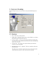
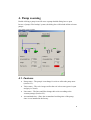
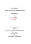
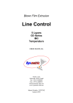
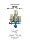
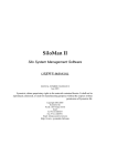
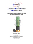
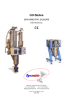
VacMon II
Vacuum System Monitor Software
USER MANUAL
MANUAL NUMBER: VACMON II
March 2009
Sysmetric claims proprietary rights to the material contained herein. It
shall not be reproduced, disclosed, or used for manufacturing purposes
without the express written permission of Sysmetric ltd.
Copyright 2003,2004
Sysmetric ltd.
P.O.B. 1022 Afula 18550
Israel
Tel 972-4-6405857
Fax: 972-4-6405911
www.sysmetric-ltd.com
[email protected]
1.
1.1.
2.
INTRODUCTION ................................................................................................................... 3
STANDARD FEATURES: ........................................................................................................... 3
MAIN SCREEN - VIEWING VACUUM SYSTEM'S COMPONENTS STATUS ........... 4
2.1. CONVEYOR ICON.................................................................................................................... 4
2.1.1.
Status ............................................................................................................................. 4
2.1.2.
Name ............................................................................................................................. 4
2.1.3.
Duration ........................................................................................................................ 4
2.1.4.
Proportional .................................................................................................................. 4
2.2. LINES ..................................................................................................................................... 5
2.3. PUMP ICON ............................................................................................................................. 5
3.
3.1.
4.
4.1.
5.
5.1.
CONVEYOR ZOOMING....................................................................................................... 6
FEATURES .............................................................................................................................. 6
PUMP ZOOMING .................................................................................................................. 8
FEATURES .............................................................................................................................. 8
ALERTS LOG ....................................................................................................................... 10
FEATURES ............................................................................................................................ 10
2
1. Introduction
VacMon is a software system for monitoring the factory's vacuum system.
Whereas the vacuum control system handles itself automatically, VacMon offers
the ability to see, online, a synoptical view of all conveyors and pumps.
This manual describes VacMon, software version 2.01
1.1. Standard Features:
•
View status and change set-points of all conveyors and pumps.
•
View the vacuum line's pump connections.
•
View the vacuum gauges of the vacuum lines.
•
The software is based on a client/server foundation, which allows all users
of a local area network to view and operate the system.
•
Modular system – allows the addition of another vacuum component by
adding it to the definition files.
3
2. Main screen - Viewing vacuum system's
components status
The status of the vacuum system's components is shown on one screen, which is
also the main screen of the software. This screen is immediately shown upon
activation of the software:
2.1. Conveyor Icon
Each conveyer has a designated icon representing its working state, name and
conveying time.
2.1.1. Status
The conveyor state causes it's icon to change as follows:
•
White – the conveyer is not active (it is switched off).
•
Grey – the conveyer is in rest mode.
•
Yellow – the conveyer is in demand mode.
•
Green – the conveyer is in receiving mode.
•
Red – the conveyer is malfunctioned.
•
Red and Green – the conveyer is malfunctioned but tries to receive
material.
2.1.2. Name
As in Windows, the conveyer name is under it's icon.
2.1.3. Duration
On the right hand side of the icon a duration time is shown, in seconds, as
follows:
•
Active conveying time – Shows the active conveying time gradually
increasing while the conveyer is in a receiving mode (green).
•
Last conveying duration – Shows the duration time of the last conveying
session.
2.1.4. Proportional
On some cases, the conveyer can receive regrind material proportionally. In that
case, the regrind proportion percentage is shown beneath the duration time.
4
2.2. Lines
Vacuum lines state is marked with colors:
•
Grey – the line is in rest mode.
•
Blue – the line is in receiving mode and is connected to the vacuum pump
which is activated and connected to the line.
Vacuum gauges, where installed, show the current vacuum depth of each line.
2.3. Pump icon
Each pump has a designated icon, it's name is beneath it and the usage percentage
is on it's right hand side.
The pump state causes it's icon to change as follow:
•
White – the pump is not active (it is switched off).
•
Grey – the pump is in rest mode.
•
Green – the pump is in working.
•
Red – the pump is malfunctioned.
Main screen sample:
5
3. Conveyor Zooming
Double clicking a conveyer icon will cause a conveyer detailed dialog box to
open.
Conveyer zoom sample:
3.1. Features
•
Flap – Reflect the real flap position.
•
Upper sensor – Reflect the sensor's led, e.g. the red light is on, as long as
the material hasn't reached the sensor yet.
•
Conveyer switch – A conveyer switch turns on and off according to the
real switch. The Enable checkbox also reflects the switch, and optionally
replaces the real switch.
•
Vacuum valve – The vacuum valve opens and turns green when the
conveyer is in receiving mode.
•
Starvation (Low reserve) – Optional – The Starve checkbox reflects the
starvation mode.
The Manual starve checkbox replaces the conveyer's Starvation switch
which enables the operator to enter starvation mode manually.
6
•
Maximum allowed time – Shows the conveyer's maximum allowed time
per each conveying quantum.
Optionally, the operator can change this value by clicking the
button.
•
Last time – Shows the last conveying duration time, in seconds.
•
Regrind – Optional – Show and set the percentage of the proportional
conveyer (section 2.1.4.).
•
Source – Optional – Set the source of the material for this conveyer. In
some cases it is imperative to define the correct source for conveying,
since the conveyer must grant permission for conveying from that source.
•
Priority button – Optional – Clicking the Priority button will put this
conveyer at the beginning of the demand queue, e.g. the receiving
conveyer will stop, and this conveyer will start conveying. It is used for
immediate testing operation after fixing a conveying problem.
7
4. Pump zooming
Double clicking a pump icon will cause a pump detailed dialog box to open.
In case of pumps "Hot backup" system, the dialog box will include all the relevant
pumps.
Two pumps screen example:
4.1. Features
•
Pump status – The pump's icon change it's color to reflect the pump state
(section 2.3.).
•
Valve status – The valve images reflect the real valves state (green is open
and gray is Closed).
•
Line status – The lines and filter change their color according to the
vacuum passage (Section 2.2.).
•
Accumulated time – Show the accumulated working time of the pump,
since it was installed in the factory.
8
•
Usage – Show the percentage of the time that the pump actually served
one of the conveyers during the last 10 minutes.
This value is also shown on the main screen, as it is worthwhile noticing if
this value changes dramatically from the norm. If so, there is a conveying
problem which may have gone undetected. After a while it becomes quite
clear what normal values are.
•
Next service – Set the time due to the pump's next service. When the
accumulated time exceeds this value, it turns red to show that the pump is
due for it's periodic service.
•
Vacuum gauge – Optional – Shows the vacuum depth.
•
Vacuum leaks test – Clicking the Vacuum test button will cause the pump
to work for 10 seconds on the line with all of it's conveyers closed.
Vacuum leaks will reduce the vacuum depth.
9
5. Alerts log
The alerts of the lines, dosing systems, vacuum and silos are logged to the
database. To see the alerts log press the
button.
Alerts log example:
5.1. Features
Order – The alert list is displayed by descending order, i.e. the alert that
ended most recently is located beneath the active alerts, below it is the alert
that terminated previously and so forth.
Active alerts – Alerts that are currently active are marked red, have no end
time and are located on the top of the list.
Acknowledgment – An alert can be acknowledged by right clicking on it
and choosing Acknowledge from the popup menu. The acknowledged alert
will turn black, so the next time the alerts log is opened it will be apparent
that this is a continuing alert that has already seen.
Time filter – The alerts list is limited by a period of time as follows:
- Last 4 hours.
- Last day.
- Last week.
10
- Last month.
- By start and end time.
Element filtering – The alerts list is subjected to the elements list on the
bottom left hand side of the alerts log. Only the marked element's alerts will
appear on the alerts list.
Filtering action – The alerts list can be filtered by marking a group of
alerts, right click and choose from the popup menu one of the following:
- Filter by selection – Unmark all unselected alert's elements i.e.
show the selection related alerts only.
- Filter excluding selection – Unmark the selected alert's elements i.e.
hides the selection related alerts.
Filter cancellation – Filtering action changes the element filtering as
described above. You can select or unselect all of the elements by right
clicking on the elements list and choosing Check all or Uncheck all from the
popup menu.
11