1
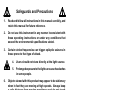
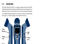
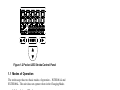
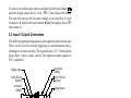
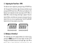
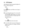
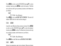
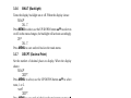
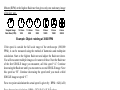
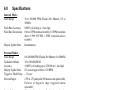
MONARCH INSTRUMENT
Instruction Manual
Distributed by MicroDAQ.com, Ltd
www.MicroDAQ.com
(603) 746-5524
Pocket LED Strobe
Portable LED Stroboscope
15 Columbia Drive
Amherst, NH 03031 USA
Phone: (603) 883-3390
Fax: (603) 886-3300
E-mail: [email protected]
Website: www.monarchinstrument.com
Safeguards and Precautions
1.
Read and follow all instructions in this manual carefully, and
retain this manual for future reference.
2.
Do not use this instrument in any manner inconsistent with
these operating instructions or under any conditions that
exceed the environmental specifications stated.
3.
Certain strobe frequencies can trigger epileptic seizures in
those prone to that type of attack.
4.
Users should not stare directly at the light source.
5.
Prolonged exposure to the light can cause headaches
in some people.
6.
Objects viewed with this product may appear to be stationary
when in fact they are moving at high speeds. Always keep
a safe distance from moving machinery and do not touch
the target.
7.
There are no user serviceable parts in this instrument. Refer
service to a qualified technician.
8.
Do not allow liquids or metallic objects to enter the
stroboscope as this may cause permanent damage and void
the warranty.
9.
Do not allow cables extending from unit to come into contact
with rotating machinery, as serious damage to the equipment,
or severe personal injury or death may occur as a result.
Distributed by MicroDAQ.com, Ltd
www.MicroDAQ.com
(603) 746-5524
10. The Pocket LED Strobe contains Lithium Ion batteries which
must be disposed of in accordance with Federal, State, &
Local Regulations. Do not incinerate. Batteries should be
shipped to a reclamation facility for recovery of the metal
and plastic components as the proper method of waste
management. Contact distributor for appropriate product
return procedures.
11. This instrument may not be safe for use in certain hazardous
environments, and serious personal injury or death could
occur as a result of improper use. Please refer to your
facility’s safety program for proper precautions.
In order to comply with EU Directive 2002/96/EC on
Waste Electrical and Electronic Equipment (WEEE):
This product may contain material which could be
hazardous to human health and the environment. DO
NOT DISPOSE of this product as unsorted municipal
waste. This product needs to be RECYCLED in
accordance with local regulations, contact your local
authorities for more information. This product may be returnable to
your distributor for recycling - contact the distributor for details.
Monarch Instrument’s Limited Warranty applies. See
www.monarchinstrument.com for details.
Warranty Registration and Extended Warranty coverage
available online at www.monarchinstrument.com.
Distributed by MicroDAQ.com, Ltd
www.MicroDAQ.com
(603) 746-5524
TABLE OF CONTENTS
1.0
OVERVIEW ......................................................................................... 1
1.1 Modes of Operation ................................................................. 2
1.1.1 Internal Mode .................................................................. 2
1.1.2 External Mode................................................................. 2
1.1.3 Charging Mode ............................................................... 3
1.2 Brightness ................................................................................ 3
1.2.1 Degree of Rotation Adjustment .................................... 4
1.2.2 Pulse Duration Adjustment ........................................... 5
2.0
PREPARATION FOR USE .................................................................. 5
2.1 Power ........................................................................................ 5
2.2 Input / Output Connectors....................................................... 6
3.0
LED STROBE OPERATION................................................................ 7
3.1 Adjusting the Flash Rate - RPM .............................................. 8
3.2 Multiply or Divide By 2............................................................. 8
3.3 Menu Options ........................................................................... 8
3.3.1 MODE .............................................................................. 9
3.3.2 BRITE (Brightness) ...................................................... 10
3.3.3 SAVE.............................................................................. 10
3.3.4 LOAD ............................................................................. 11
3.3.5 UNITS ............................................................................ 11
3.3.6 BKLIT (Backlight) ......................................................... 12
3.3.7 DECPT (Decimal Point) ................................................ 12
3.3.8 INPUT (Input Pulse Polarity) ....................................... 12
4.0
USING THE STROBOSCOPE TO MEASURE RPM ........................ 13
5.0
BATTERIES ....................................................................................... 15
5.1 Low Battery Indication........................................................... 15
5.2 Charging the Batteries........................................................... 15
5.3 Battery Disposal ..................................................................... 16
6.0
SPECIFICATIONS ............................................................................. 17
7.0
OPTIONS AND ACCESSORIES / SENSORS .................................. 19
Distributed by MicroDAQ.com, Ltd
www.MicroDAQ.com
(603) 746-5524
1.0
OVERVIEW
The Pocket LED Strobe (PLS) is a rugged, portable battery powered LED
(Light Emitting Diode) stroboscope used for inspection and to stop motion to
determine the speed of rotating objects. The unit is ergonomically designed
for comfortable hand held operation or it may be mounted on a tripod using
the integral ¼ -20 UNC bushing on the underside of the unit.
1/4-20
Bushing
EXT
MENU
Charger
Jack
Input
Jack
Output
Jack
Battery
Cover
Figure 1.1 Pocket LED Strobe
The Pocket LED Strobe has a two-line backlit alpha-numeric liquid crystal
display (LCD) and a four-key keypad that enables the user to control the
operation of the unit. The LCD display has several icons which will be
explained later in this manual.
Distributed by MicroDAQ.com, Ltd
www.MicroDAQ.com
(603) 746-5524
1
EXT
Figure 1.2 Pocket LED Strobe Control Panel
1.1 Modes of Operation
The stroboscope has two basic modes of operation – INTERNAL and
EXTERNAL. The unit does not operate when in the Charging Mode.
1.1.1
Internal Mode
The strobe is in the Internal Mode when nothing is plugged into the
input jack. In the internal mode the strobe generates its own timing
signals and the user can adjust the flash rate – see Section 3.1.
1.1.2
External Mode
In the External Input Mode the user can’t make any flash rate
adjustments. The flash rate is a function of the input signal. This
mode is used to synchronize the flash to an external event (for
example, from an optical sensor) to stop or freeze motion. The flash
will be triggered on the rising or falling edge (menu selectable) of
the external input pulse. The strobe is in the External Input Mode
2
Distributed by MicroDAQ.com, Ltd
www.MicroDAQ.com
(603) 746-5524
whenever there is a plug in the input jack. When the strobe is in
the External Input Mode, EXT will be displayed.
When an external input is applied to the unit and the strobe is put
in the Tachometer Mode, the unit will read the signal from the
external input (sensor) and display the reading on the LCD display
without flashing the lamp. When there is a valid external signal the
on target indicator
will turn on. The strobe will not flash in
the Tach (Tachometer) Mode. To exit the External mode, remove
the device from the input jack.
1.1.3
Charging Mode
The Charging Mode is when the strobe has the battery recharger
plugged into it. The strobe will not operate while charging. The
status of the charge is indicated by the LED on the charger.
While charging the LED on the charger is RED; when the charge
is complete the LED will turn GREEN. USE ONLY THE
CHARGER SUPPLIED WITH THE STROBE - Model LBC-U.
1.2 Brightness
GLOSSARY:
LED – Light Emitting Diode
° = degree. One rotation = 360°
msec – millisecond = 1/1,000 of a second
µsec – microsecond = 1/1,000,000 of a second
The strobe’s brightness depends on how wide the LED flash pulse is;
the wider the pulse, the brighter the visual output from the LEDs. Since
the strobe is primarily used on reciprocating or rotating targets, there is
a downside to the wider flashes. All strobes work by giving short bursts
of light (the pulse width) at a rapid repetition rate (the flash rate). Strobes
rely on the persistence of the human eye (the ability to remember and
image) and its response to bright light to give an apparent stopped motion
Distributed by MicroDAQ.com, Ltd
www.MicroDAQ.com
(603) 746-5524
3
image. Imagine a shaft rotating at 6000 RPM or one rotation every 1/100
of a second (10 msec). If the strobe flashes once every 10 msec for a brief
moment, the user sees the flash at the same spot in the rotation of the
shaft and the persistence of the eye remembers this until the next flash
making the shaft appeared to be stopped. As the target is rotating there
is some movement evident during the strobe flash. The longer the flash
duration, the more obvious the rotation is and this increases the blur.
This blur can be calculated – if the shaft takes 10 msec to complete
one revolution and the strobe flash duration is 100 µsec (1/100 of a
millisecond), the shaft will turn:
(flash duration/time per rotation) x 360° which is (.0001/.01) x 360 = 3.6°.
So you will see the shaft move 3.6°. As the flash pulse widens you will
see greater degrees of rotation which results in more blur and a brighter
perceived illumination (the LEDs are on longer so the average light the
eyes see is greater). The trade-off is blur versus brightness. One also has
to take into account tangential velocity (rotational speed) – the further
away the rotating point is from the center axis, the faster the tangential
velocity and the worse the blur appears to be – it is always the same
number of degrees of rotation but the physical length of the blur gets
bigger as the point moves faster. The strobe adjusts the width of the pulse
automatically to keep the degree of rotation visible constant.
There are two methods of adjusting the flash pulse width and hence the
brightness and consequently the blur.
1.2.1
Degree of Rotation Adjustment
The first method is to adjust the flash pulse width for degree of
rotation visible (blur). The user can set this from 0.1 to 18 degrees
out of 360. The higher the setting, the brighter the strobe appears
to be but the more blurred the target is. Optimal setting to stop
motion is 1 to 3.6°. The number of degrees is a proportional amount
4
Distributed by MicroDAQ.com, Ltd
www.MicroDAQ.com
(603) 746-5524
and remains constant as the flash rate increases or decreases. The
strobe automatically calculates how wide the pulse width should
be at different flash rates to keep the blur constant – the faster the
flash rate, the narrower the pulse width. The pulse width equals:
(setting in degrees/360) x (1/flash rate in Hz).
Thus the blur remains constant no matter what the flash rate*.
1.2.2
Pulse Duration Adjustment
The second method is to adjust the flash pulse width to a fixed
number of microseconds. Here the user sets the flash pulse width
in microseconds not degrees. As the flash rate increases, the pulse
width stays the same* and the image will get brighter and more
blurred as the flash width remains constant*. The degree of rotation
visible changes to keep the pulse width of the flash constant*.
*Note: There are two limits maintained by the strobe – the pulse
can never be greater than 2500 µs nor can it exceed 18° of rotation.
The strobe automatically adjusts these values as the flash rate is
increased or decreased to maintain these limits at all times. For
example - at a flat rate of 600 flashes per minute, 14° of blur
represents a flash pulse width of 3800 µsec. The Strobe will limit
this value to 2500 µsec or 9° of rotation (blur).
2.0
PREPARATION FOR USE
The Stroboscope may be hand held or mounted on a tripod or other user
supplied bracket using the ¼-20 UNC bushing on the underside of the unit.
2.1 Power
The LED Strobe is battery powered and has internal rechargeable
batteries. The unit should be charged before use (see Section 5.0).
The actual operating time of the stroboscope depends on the flash pulse
width. Narrower flash widths increase the operating time.
Distributed by MicroDAQ.com, Ltd
www.MicroDAQ.com
(603) 746-5524
5
To turn on the stroboscope, depress and hold the left most button
until the display shows the rev level - REVXX then release the button.
The unit will start up with the same settings it was last left at. To turn
the power off, hold the left most button ◄ until the display shows OFF
then release it.
2.2 Input / Output Connectors
The strobe has input and output jacks on the right side of the stroboscope.
These can be used for external triggering or synchronization (daisychaining two or more strobes). These jacks accept 1/8” (3.5mm) phone
plugs (input - stereo, output - mono). The input and output signals are
TTL compatible.
Common
(GND)
+3.2V Out to
Sensor
Signal Input
+3.2V Out to
Sensor
Common
(GND)
Signal Input
Figure 2.1 Input Connector Detail (Stereo plug)
Signal Output
Common
(GND)
Common
(GND)
Signal Output
Figure 2.2 Output Connector Detail (Mono plug)
6
Distributed by MicroDAQ.com, Ltd
www.MicroDAQ.com
(603) 746-5524
The input jack (closer to the front of the strobe ▲) enables an external
signal to trigger the strobe. Inserting a plug into the input jack will
automatically put the strobe into the External Mode. When the plug is
removed, the strobe will be put back into the Internal Mode.
With no external input, the output jack (closer to the rear of the strobe
▼) provides a TTL compatible pulse from the strobe’s internal oscillator.
If an external input is applied, the output pulse is in sync with the input
pulse. This output pulse may be used to trigger a second stroboscope
synchronously to illuminate larger areas. Many strobes can be “daisy
chained”. The output jack of one strobe is connected to the input jack of
the next strobe causing all the strobes to flash together and be controlled
by the first strobe in the chain.
Note: Cables should not exceed 8 feet or 2.5 meters in length in
order to comply with the CE rating of this product.
3.0
LED STROBE OPERATION
The Strobe is controlled via the four buttons on the face of the unit. The
button on the left (A) is also the power button.
A
B
C
D
Figure 3.1 LED Strobe Keypad
Distributed by MicroDAQ.com, Ltd
www.MicroDAQ.com
(603) 746-5524
7
3.1 Adjusting the Flash Rate – RPM
The flash rate can be adjusted by pressing the large UP/DOWN key
(D). Pressing the UP end of the key ▲ will increase the flash rate and
pressing the DOWN end of the key ▼ will decrease the flash rate. The
flash rate can be adjusted in decades by pressing the LEFT ◄ (A) or
RIGHT ► (C) which will change which digit is adjusted. The active
digit will blink. As the flash rate is increased or decreased, the active
digit will roll over to the next significant digit. The LEFT and RIGHT
digit selection will wrap around as shown below.
KKKKKK KKKKKK
<<<<<<<<
>>>>>>>>
3.2 Multiply or Divide By 2
The strobe flash rate can be instantly doubled (x2) or halved (÷2) by
pressing the MENU button (B). The lower display will show X2/2.
Pressing the UP/DOWN button (D) will double ▲ or halve ▼ the
flash rate. This is useful in determining actual rotational speed – refer
to the section on speed measurement – Section 4. Note that if doubling
or halving the flash rate will cause the strobe to exceed its capability,
the unit will be limited to the highest or lowest value it can generate
respectively. To exit this mode, press the LEFT ◄ (A) button.
3.3 Menu Options
To enter the Setup Mode it is necessary to press the MENU button (B)
twice. The first press will enter the x2 /2 mode as described above, the
second press will enter the Setup Mode. The top line of the display
will show SEtUP and the bottom line will show the setup options. Use
the UP/DOWN button ▲▼ to scroll through the setup options. Press
8
Distributed by MicroDAQ.com, Ltd
www.MicroDAQ.com
(603) 746-5524
MENU (B) at any time to select that setup option. Note that currently
selected options are indicated by the star icon ( ).
Setup options are in order as follows:
MODE > BRITE > SAVE > LOAD > UNITS > BKLIT > DECPT >
INPUT
These options are described in the following sections. Note that the
order of the options within each setup option may change depending
on current operating settings.
3.3.1
MODE
Set the strobe into the flash (strobe) mode or the tachometer (no
flash) mode. When the display shows:
SETUP
MODE
Press the MENU button to enter. The mode can be set to Tach or
Strobe.
Tach - No LED flash - use external input to show RPM
TACH
MODE
Press MENU to save and return to the main menu, or
use UP/DOWN button ▲▼ to change to:
Strobe - Internal generator - flash LEDs
STRBE
MODE
Press MENU to save and return to the main menu or press ◄ to
return to the main menu without saving. The unit will indicate
DONE when the value has been changed.
Distributed by MicroDAQ.com, Ltd
www.MicroDAQ.com
(603) 746-5524
9
3.3.2
BRITE (Brightness)
Adjust the flash pulse width and consequently the brightness. See
Section 1.2. When the display shows:
SEtUP
BRITE
Press the MENU button to enter. Width can be set in degrees or
microseconds.
DEG - Set the flash width in degrees 0.2° to 18°. Use the UP/
DOWN button ▲▼ to change the degrees in 0.2° steps. Note
that the decade being edited can be changed using the LEFT
◄ or RIGHT ► buttons.
5.6
DEG
Press the MENU button to move to microseconds.
uSEC - Set the flash width in microseconds. Maximum and
minimum are equivalent to 0.2 to 18 degrees or 2500 uSec,
whichever is less.
1234
uSEC
The display will be a conversion of the degrees to microseconds
for the current flash rate. To accept this press MENU again.
To adjust the flash rate in microseconds, use the ▲▼ button.
Note that the decade being edited can be changed using the
LEFT ◄ or RIGHT ► buttons.
Press MENU to save and return to the main menu.
3.3.3
SAVE
Saves the current flash rate to a memory location. When the
display shows:
SEtUP
10
SAVE
Distributed by MicroDAQ.com, Ltd
www.MicroDAQ.com
(603) 746-5524
Press MENU to select, use the UP/DOWN button ▲▼ to select
a memory location, press MENU to select the location. The flash
rate is shown on the top row, memory location on the bottom row
(see below).
3600
SM 3 (SM = Save Memory)
Press MENU to save and EXIT OUT OF MENU. The unit will
indicate DONE when the value has been changed.
3.3.4
LOAD
Loads the saved flash rate from a memory location. Press MENU
to select, use the UP/DOWN button ▲▼ to select the memory
location, press MENU to select. The flash rate is shown on the top
row, memory location on the bottom row (see below).
3600
RM 3 (RM = Recall Memory)
Press MENU to recall flash rate and EXIT OUT OF MENU.
3.3.5
UNITS
Selects the engineering units for the display. When the display
shows:
SEtUP
UNITS
Press MENU to select, use the UP/DOWN button ▲▼ to select
the units. The units depend on the MODE of the unit. The options
are RPM/RPS (Revolutions per Minute/Second).
Unit
RPM
Press MENU to save and exit back to the main menu or press ◄
to return to the main menu without saving. The unit will indicate
DONE when the value has been changed.
Distributed by MicroDAQ.com, Ltd
www.MicroDAQ.com
(603) 746-5524
11
3.3.6
BKLIT (Backlight)
Turns the display backlight on or off. When the display shows:
SEtUP
BKLIT
Press MENU to select, use the UP/DOWN button ▲▼ to select on
or off. As the status changes, the backlight will activate accordingly.
OFF
BKLIT
Press MENU to save and exit back to the main menu.
3.3.7
DECPT (Decimal Point)
Set the number of decimal places to display. When the display
shows:
SEtUP
DECPT
Press MENU to select, use the UP/DOWN button ▲▼ to select
none, 1 or 2.
nonE
DECPT
Press MENU to save and exit back to the main menu or press ◄
to return to the main menu without saving. The unit will indicate
DONE when the value has been changed.
3.3.8
INPUT (Input Pulse Polarity)
Set the active edge of the input pulse. When the display shows:
SEtUP
INPUT
Press MENU to select, use the UP/DOWN button ▲▼ to select
NEGative or POSitive.
nEg
EDGE
Press MENU to save and exit back to the main menu or press ◄
12
Distributed by MicroDAQ.com, Ltd
www.MicroDAQ.com
(603) 746-5524
to return to the main menu without saving. The unit will indicate
DONE when the value has been changed.
At the MAIN MENU press the LEFT ◄ button to exit to the operational
condition.
4.0 USING THE STROBOSCOPE TO MEASURE
RPM
The primary use for a stroboscope is to stop motion for diagnostic inspection
purposes. However the stroboscope can be used to measure speed (in RPM
/ RPS). In order to do this several factors need to be considered. First, the
object being measured should be visible for all 360° of rotation (e.g. The
end of a shaft). Second, the object should have some unique part on it, like a
bolt, key way or imperfection to use as a reference point. If the object being
viewed is perfectly symmetrical, then the user needs to mark the object with
a piece of tape or paint in a single location to be used as a reference point.
Look only at the reference point.
If the speed of rotation is within the range of the stroboscope, start at a
higher flash rate and adjust the flash rate down. At some point you will stop
the motion with only a single reference point of the object in view. Note that
at a flash rate twice the actual speed of the image you will see two images
(reference points). As you approach the correct speed you may see three,
four or more images at harmonics of the actual speed. The first SINGLE
image you see is the true speed. To confirm the true speed, note the reading
and adjust the stroboscope to exactly half this reading, or just press the ÷2
button. You should again see a single image (which may be phase shifted
with respect to the first image seen).
For example, when viewing a shaft with a single key way you will see one
stationary image of the key way at the actual speed and at 1/2, 1/3, 1/4, etc.
of the actual speed. You will see 2 images of the key way at 2 times the actual
speed, 3 key way at 3 times, etc. The FPM equals the shafts Revolutions Per
Distributed by MicroDAQ.com, Ltd
www.MicroDAQ.com
(603) 746-5524
13
Minute (RPM) at the highest flash rate that gives only one stationary image
of the key way.
Stopped Image
Flash Rate (FPM)
1/4 times
1250
1/2 times
2500
1 time
5000
2 times
10000
3 times
15000
4 times
20000
Example: Object rotating at 3000 RPM
If the speed is outside the full scale range of the stroboscope (300,000
FPM), it can be measured using the method of harmonics and multipoint
calculation. Start at the highest flash rate and adjust the flash rate down.
You will encounter multiple images so be aware of these. Note the flash rate
of the first SINGLE image you encounter, call this speed “A”. Continue
decreasing the flash rate until you encounter a second SINGLE image. Note
this speed as “B”. Continue decreasing the speed until you reach a third
SINGLE image at speed “C”.
For a two point calculation the actual speed is given by: RPM = AB/(A-B)
For a three point calculation: RPM = 2XY(X+Y)/(X-Y)2 where
X = (A-B) and Y = (B-C)
If a Remote Optical Sensor or Magnetic Sensor is used to sense one pulse per
revolution (External mode), the readout will display directly in RPM (FPM)
without any adjustment required.
In instances when you can shut down the device and install a piece of reflective
tape, then an optical tachometer is easier to use for RPM measurement.
Stroboscopes must be used when you can’t shut down the device. The
human eye is not easily tricked into seeing a stopped image by a stroboscope
when the flash rate is slower than 300 FPM. Therefore, stroboscopes are just
about impossible to use below 300 FPM for inspection or to measure RPM.
14
Distributed by MicroDAQ.com, Ltd
www.MicroDAQ.com
(603) 746-5524
5.0
BATTERIES
The Pocket LED Strobe is fitted with a rechargeable Lithium Ion battery
pack. These batteries are prone to self-discharge over time. For maximum
performance, charge the batteries prior to use and do not store in hot locations. The strobe uses an external charger. Allow 3-5 cycles of charging and
discharging for batteries to reach full capacity. When not in use, the batteries
should be charged at least every three months, otherwise the battery capacity
will be reduced or the batteries may become unusable.
The enclosure contains control electronics to properly protect and safely
charge the batteries. Never remove the batteries from the enclosure and
attempt to charge externally. Always use the charger supplied – LBC-U.
5.1 Low Battery Indication
When the batteries are charged, there will be no battery icon indication.
When the batteries are low, the Low Battery icon will appear in the
display. The strobe may still be used for a short time.
Low Battery Icon =
Outline blinking (very little time left)
The strobe has a protection feature that prevents the strobe from operating if
the battery voltage is too low. This condition is indicated by no flash and
the display shows “LO BAT”. At this time the batteries must be recharged.
5.2 Charging the Batteries
The unit may be recharged at any time. You do not need to wait until
the low battery condition is indicated.
To charge the strobe with the recharger:
1. Turn the strobe off.
2. Plug the Li-Ion charger cable into the recharger socket on the
left of the keypad.
3. Plug the recharger into an AC mains wall outlet (115/230 Vac).
Distributed by MicroDAQ.com, Ltd
www.MicroDAQ.com
(603) 746-5524
15
CAUTION:
Use of rechargers other than the one supplied
(Model LBC-U or F037-005-W) will damage the
stroboscope and void the warranty. DO NOT
LEAVE A CHARGER THAT IS NOT PLUGGED INTO
THE AC POWER CONNECTED TO THE STROBE.
When charging, the strobe will indicate CHRGE in the bottom right of
the display when turned on and then it will shut off. The recharger will
fast charge the batteries for about 4-5 hours and then trickle charge
the batteries. The charger has an LED to indicate charge: LED Red
= batteries charging. LED Green = batteries charged or charger not
connected.
The battery pack may be replaced by removing the battery cover and
unplugging the battery pack. The new battery pack can be inserted and
plugged into the unit. Replace the battery cover.
5.3 Stroboscope Disposal
Prior to disposing of the battery-powered strobe, the user
must remove the Lithium Ion batteries. To do this, remove
the battery cover, unplug the battery pack and dispose
according to local laws governing battery disposal. The
rest of the parts may now be disposed of.
16
Distributed by MicroDAQ.com, Ltd
www.MicroDAQ.com
(603) 746-5524
6.0
Specifications
Internal Mode:
Flash Range
Flash Rate Accuracy
Flash Rate Resolution
Display Update Rate
External Modes:
Flash Range
Tachometer Mode
Accuracy
Display Update Rate
Trigger to Flash Delay
External Input:
Output Pulse
Pulse In to Out Delay
Time Base
Display
Indicators
Memory
30 to 300,000 FPM (Flashes Per Minute), 0.5 to
5000Hz
0.005% of setting or ± last digit
0.01 to 1 FPM (menu selectable), 0.1 FPM resolution
above 9,999.99 FPM, 1 FPM resolution above
99,999.9
Instantaneous
0 to 300,000 FPM (Flashes Per Minute), 0 to 5000Hz
30 to 300,000 RPM
±0.005% of reading up to 250,000 or ± last digit
0.5 second typical above 120 RPM
~ 15 µsec
2.5V to 12V peak pulse 500 nanosec min pulse width,
Positive or Negative edge triggered (menu
selectable)
3V pulse. One pulse per flash in internal mode.
Mimics input pulse in external mode.
< 0.2 µsec (External Mode)
Ultra Stable Crystal Oscillator
LCD display with 6 numeric 0.506 inch [12.85 mm]
high digits and 5 alphanumeric 0.282 inch [7.17 mm]
high digits
Low Battery, On Target, Select, TACH, and EXT icons
Last setting before power down is remembered and
restored on next power up. 5 user settable memory
locations
Distributed by MicroDAQ.com, Ltd
www.MicroDAQ.com
(603) 746-5524
17
Flash Duration
Input Power
Light Output
Run Time
Charge Time
Weight
Adjustable 0.5 to 2500 microseconds or .1 to 18 degrees
of rotation (auto adjusts with flash rate)
Battery powered: Internal Li-Ion Rechargeable Batteries
3.6Vdc
Average: 1800 Lumens @6000 FPM 8” from lens
5 - 6 hours typical at 6000 FPM, and 2.8° pulse width
with fully charged batteries
4-5 hours typical with supplied charge.
0.6 lbs [0.27 kg] including batteries
Operating Temperature 32 - 104 °F [0-40 °C]
Humidity
Maximum relative humidity 80% for temperature up
to 88 °F [31 °C] decreasing linearly to 50% relative
humidity at 104 °F [40 °C]
Safety
Compliance
This product is designed to be safe for indoor use
per IEC61010-1.
CE EN61326-1:2006 EMC 2004/108/EC
This product is CE certified and ROHS compatible.
Manufactured in an ISO9000 facility.
For troubleshooting information and technical support visit
www.monarchinstrument.com.
18
Distributed by MicroDAQ.com, Ltd
www.MicroDAQ.com
(603) 746-5524
7.0
OPTIONS AND ACCESSORIES / SENSORS
CA-4044-6
6 foot [1.8 m] Pulse Input / Output cable, 1/8 inch [3.5 mm]
male phone plug to male BNC connector
T-5
Reflective tape - 5 foot [1.5 m] roll, 0.5 inch [12.7 mm]
wide
CC-13
Latching carrying case for Strobe with provision for
accessories
Mini Tripod
Miniature tripod with 1/4” x 20 threaded stud
LBC-U
Universal Li-Ion Recharger, 115/230 Vac with USA
ROLS-P
Remote Optical Laser Sensor with 8 foot [2.5 m] cable for
triggering strobe
Distributed by MicroDAQ.com, Ltd
www.MicroDAQ.com
(603) 746-5524
19
Printed in the U.S.A.
Copyright 2014 Monarch Instrument, all rights reserved
Distributed by MicroDAQ.com, Ltd
www.MicroDAQ.com 1071-4235-113
(603) 746-5524 -0314