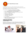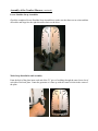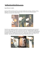
1
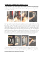
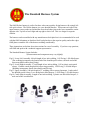
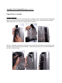
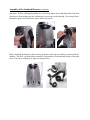
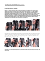
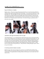
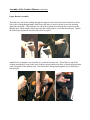
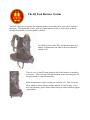
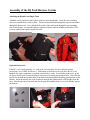
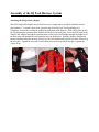
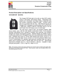
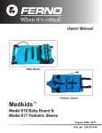
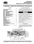
Buoyancy Compensator
User’s Guide
Ocean Management Systems, Inc.
P.O. Box 146, Montgomery, NY 12549
Phone: 845.692.3600 fax: 845.692.3623
www.omsdive.com
E-mail: mailto:[email protected]
Buoyancy Compensator
User’s Guide
Thank you for choosing OMS,
OMS buoyancy compensators have been constructed from rugged materials with unique features
adaptable to advanced underwater environments. The general design philosophy allows for complete
system integration of a number of components achieving high lift capacities, low drag, and increased safety
through redundancy. With a selection of different harnesses, different air cells and accessories, a diver can
configure his or her system for the specific environment they are operating in. This equipment is intended
for use by individuals with the training and experience to dive these environments safely
General Precautions & Warnings
•
Before using this buoyancy compensator (BC), you must receive instruction and
certification in SCUBA diving and buoyancy control from a recognized training agency.
Use of SCUBA equipment by uncertified or untrained persons is dangerous and can result in
injury or death.
•
Read this owner’s manual completely before attempting to use your BC, and become
familiar with it first in a controlled environment such as a swimming pool, in order to weight
yourself properly and to become comfortable with using its many features and adjustments.
•
Before every dive, perform a complete pre-dive inspection according to the procedure
prescribed in this manual, to ensure that all components are functioning properly and no
signs of damage or leaks are present. If you find that your BC is not functioning properly or
is damaged, remove it from service until it can be repaired.
•
Your BC is not a lift bag. Do not use it to bring heavy objects to the surface. Doing so may
cause permanent damage to the BC, and could also result in serious injury or death due to
embolism or decompression sickness.
•
In an emergency such as an out of air situation or uncontrolled descent, it is important to
remove and jettison weight immediately. Do not depend solely on using your BC’s power
inflator to lift you to the surface.
•
In the event of an uncontrolled, rapid ascent, it is important to immediately begin venting air
from the BC. Continue venting air to slow your ascent rate if neutral buoyancy cannot be
reestablished.
•
Do not inhale from your oral inflator. The BC may contain harmful contaminants or gasses,
which could cause suffocation or injury.
•
The function of your buoyancy compensator is to help you maintain neutral buoyancy while
in a comfortably balanced, face-down swimming position underwater. It is also designed to
provide you with flotation so that you can rest on the surface, but it is not designed to
function as a life preserver or personal flotation device (PFD). A buoyancy compensator
(BC) is not a life jacket. It is not designed to provide face-up flotation in all situations, and
therefore it does not meet U.S. Coast Guard regulations for a life preserver or personal
flotation device (PFD).
•
Have your OMS equipment inspected and serviced annually by an authorized OMS dealer
or at any time you have any concerns about your equipment’s function or condition.
Table of Contents
General Warnings ………………………………. 1
Introduction……………………….…………..…. 4
Harnesses………………………………………… 6
Continuous Weave………………6
Standard Harness……………….9
Comfort Harness………………..17
IQ Pack………………………….25
Air Cells…………………………………………..28
Non-Banded……………………28
Elastomeric Banded……………29
Inflators and Dump Valves…..32
Attaching Cylinders……………………………...34
Nylon Cam Bands……………..34
Single Tank Adapter……..……36
Double Tank Bands…………...37
Installing Accessories…….………...………….…39
Weight Pockets………………...39
Operation…………………………………………40
Warranty………………………………….………41
Service Record…………………….……………...42
3
Introduction to OMS
Buoyancy Compensators
OMS buoyancy systems are built around a modular design that allows a diver to customize his system.
Typically, a complete system consists of a harness system, an air cell, accessory pockets, and a system to
attach cylinders. It is important for a diver to configure a system that fits properly and has enough lift to
comfortably support the diver and cylinders at the surface. Tools and emergency items (marker buoys,
signal devices, etc.) should be secured such that they are easily available yet do not pose an entanglement
hazard to guidelines and mooring ropes. All this is possible with OMS products.
Harnesses
IQ Pack A ‘soft pack’ harness system that can be used as part of a light weight travel rig or can be fitted
with a metal back plate for use with high capacity dual cylinders.
One Piece Harness A simple harness with no sternum strap or shoulder release buckles, minimal harness
for maximum reliability.
Standard Harness System A single side release on the shoulder strap makes for easy doffing. This
harness includes features like extra ‘D’ rings and a sternum strap assembly.
Comfort Harness A full featured harness with side release buckles on both padded shoulder straps. This
harness includes a sternum strap and adjustable ‘D’ ring attachment points.
These harnesses can be assembled with OMS stainless steel or aluminum back plates.
Air Cells
OMS air cells (BCs) are available in different lift capacities and different configurations. It is extremely
important that the air cell you select has enough buoyancy to support the diver and cylinders at the surface.
OMS air cells are available with redundant internal bladders and with elastomeric retraction bands to help
minimize the volume of the uninflated BC. Standardized fittings allow inflator mechanisms and dump
valves to be configured a number of different way.
Lift (lbs) Single
Retraction
Bands
Dual Bladder
#32
N/A
#35
N/A
#45
•
N/A
N/A
N/A
4
#60
Optional
•
#94
Optional
Introduction to OMS Buoyancy Compensators (continued)
Accessory Pockets
OMS BCs can be made weight integrated by the addition of weight integration pockets (available in two
styles). There are also pockets for tools and accessories. The ‘butt mounted’ Emergency Deployment
System can be attached to the back plate to carry emergency signal equipment.
Attaching Cylinders
There are a several ways that cylinders are attached to OMS BCs depending on the weight and number of
cylinders. Dual cylinders will require secure steel bands bolted to a metal back plate. You must insure that
the bands are matched to the cylinder size and to the distance between the cylinders. OMS bands are
precisely sized to OMS manifolds to prevent dangerous physical stress across the manifold. A single tank
adapter is required to attach a single cylinder to a metal plate. The IQ Pack can accommodate a single tank
without a single tank adapter by threading nylon cam bands through webbing on the back of the harness.
5
HARNESSES
Continuous Weave Harness System
The OMS Continuous Weave Harness system (BP166) system includes:
• 11 feet of 2” black webbing assembled with a SS grommet in the center (main harness). Length may
vary slightly.
• 3.5 feet of 2” black webbing with a loop sewn at one end (crotch strap). Length may vary slightly.
• 6 SS D-rings
• 6 SS slides
• 1 SS quick release
You will also need a back plate. It is recommended that you use an OMS steel or aluminum back
plate. OMS back plates are superior in quality and provide smoother edges to promote a longer life
to webbing and other gear that may come into contact with plate edges.
Assembly of the Continuous Weave Harness
1. Start by inserting one end of the main harness webbing through the top slot (from the back
towards the front of the back plate) and continue pulling the webbing until the grommet comes
through followed by another 5” of webbing. Insert the same end of the webbing back through the
angled slot below the top slot; this time from front to back. Pull the entire length through to the
back of the plate until the grommet and 5” of webbing following the grommet, are through. Then
turn the plate around so you’re looking at the rear of the plate and insert the end of back through the
angled lower slot on the opposite side of the plate. Adjust the webbing until the grommet is
centered with the bolthole of the plate. Insert the same end of webbing back up and through the top
slot all the way as far as it will go and pull it tight (from front to back.).
This completes the upper most assembly of the harness. Be
sure that the grommet is centered with the hole in the black
plate and that the harness looks like these pictures.
Assembly of the Continuous Weave Harness (continued)
2. Now install the ‘D’ rings onto the shoulder straps by sliding the shoulder webbing through one
slot of a stainless steel slide, through a ‘D’ ring then back through the second slot of the slide. Place
the ‘D’ rings so they will be close to the diver’s collar bone. Fine adjustments to their placement
can be made after assembly.
3. Next the shoulder straps thread through the angled slots at the lower right and left corners of the
plate. The webbing threads through the inner slot first from front to back then through the outer slot
back to front. The free end becomes the waist band. Repeat this on both sides. Install the waist Dring(s) on the waist strap. Some like one D-ring on the Left, some like one on each side. It’s up to
you but OMS includes enough for both sides. Installation is the same as the shoulder D-rings and
exact adjustments should be made later while wearing your exposure suit. Their final resting place
should be about mid body. Remember, adjustments to the placement of ‘D’ rings can be made later
while wearing your exposure suit. Install the waist quick release on the left waist band so as you
have a left hand release. Get it close and make adjustments later. Remember to install a pocket,
knife or line cutter (if one desires to do so) on the waist strap before installing the buckle.
4. Now prepare the crotch strap for installation by installing a ‘D’ ring on a slide just like the
shoulder straps. Slide another stainless steel slide onto the crotch strap opposite the looped end.
The non-looped end of the crotch strap will feed through the lower middle slot from the back then
weave through the stainless steel slide. Adjustments to the length of the crotch strap will be made
here and the looped end will thread onto the waist band.
Assembly of the Continuous Weave Harness (continued)
5. Put on your exposure suit to check adjustments. Try it out in the water and fine-tune it as
necessary. The main harness should fit comfortably and not be too tight. Be sure it’s not sloppy.
Adjust the shoulder/chest D-rings to your collarbone. Adjust your waist (s) D-rings to mid body
(side). The crotch strap should be a loose fit with around an inch of slack (when pulling it up
through the legs it will come an inch or so higher than the waist strap). The rear D-ring on the
crotch strap (closest to the cylinders) should be adjusted to where it is easily reachable and won’t
interfere with the cylinders or the divers fin kick. The scooter ring should be located a few inches
from the bottom of the loop. You can turn it inside the loop when you don’t need it. Accessorize
and fine-tune your new harness to your style of diving. This is what your completed harness should
look like.
The Standard Harness System
The OMS Deluxe harness is perfect for those who want a quality diving harness with a single left
side quick release. The Deluxe harness is a cross shoulder harness. This means each side of the
upper harness crosses at the top (behind the divers head) then joins to the lower assemblies on the
opposite side. Top left to lower right and top right to lower left. This is a design for superior
comfort.
The harness can be assembled with any manufacturers back plate but it is recommended it be used
with the OMS Aluminum or Stainless Steel back plate due to the superior quality and softer edges.
OMS plates extend the life of the harness webbing considerably.
These instructions are broken down into sections for ease of assembly. If you have any questions,
call OMS and speak with a technical support representative.
The Standard Harness System Includes:
(Measurements and components may vary slightly)
Fig# 1. Lower Left Assembly: 60 inch length of two inch webbing, 1-SS D-ring, 1-SS slide/keeper.
(The webbing incorporates the female end of the shoulder quick release, the male end of the
chest strap buckle and a chest D-ring)
Fig# 2. Lower Right Assembly: 57 inch length of two inch webbing, 1-SS or plastic waist quick
release, 1-female crotch strap buckle/scooter ring assembly, 1-SS D-ring, 1-SS slide/keeper.
(Webbing incorporates female chest buckle and SS ring)
Fig# 3. Upper Assembly: 100 inch length of 2” webbing with a centered grommet, 1-male end of
the shoulder quick release, 2-two inch plastic slides/keepers, 3-SS D-rings, 3-SS slide/keepers.
Fig# 4. Crotch Strap Assembly: Length of one-inch webbing, 2-plastic one-inch slides/keepers, 1male end of the crotch buckle.
Fig 1
Fig 2
Fig 3
Fig 4
Assembly of the Standard Harness
Lower Harness Assemblies
Lower Left Assembly (Fig 1): Holding the 60 inch lower left assembly with the D-ring facing to
your right (when looking at the plate), insert the free end of webbing through the inside lower slot
of the divers left hand side of the plate from front to back. Now pull the webbing back through the
outer lower left hand slot from back to front. Leave approximately 14” of webbing between the
plate slot and the female quick release. Final adjustments can be made later while wearing your
exposure suit.
Lower Right Assembly (Fig 2): Insert the free end of webbing through the divers right side lower
inner most slot of the plate from front to back then string it back through from back to front. Leave
approximately 14” of webbing between the plate slot and the SS ring with female chest buckle. Be
sure buckle is facing the correct position as shown in the far right image below (writing on buckle is
facing up). Final adjustments can be made later while wearing your exposure suit.
Assembly of the Standard Harness (continued)
Upper Harness Assembly
Upper Left & Right:
Step one: String one end of the 100 inch length of webbing with the centered grommet, through the
uppermost slot of the divers left side of the plate from back to front. Pull the grommet through
along with another five inches of webbing after the grommet.
Step two: String the webbing back trough the lower angled slot from front to back (directly under
the upper slot) and pull the grommet through. Adjust so the grommet lines up with the bolthole in
the center of the back plate.
Assembly of the Standard Harness (continued)
Step three: Pull the webbing through the lower slot on the upper divers right hand side of the plate
from back to front making sure the webbing isn’t twisted once pulled through. Now string it back
through the upper most slot directly above from front to back.
Before installing the hardware, make sure the grommet on the upper assembly is centered with the
bolthole. The diver’s left hand lower assembly is positioned so as the attached D-ring is facing the
diver’s left side if webbing is on edge (see image below).
Assembly of the Standard Harness (continued)
Upper Right Hardware Assembly
Install a 2” plastic slide/keeper onto the upper right portion of the harness. Be sure that when
installed, the webbing is showing in the center portion of the slide/keeper. The slide should be
placed around 2 inches or so from the edge of the plate. Next, install the D-ring assembly by
stringing the webbing through the top slot of a SS slide/keeper from back to front. String a D-ring
through the same piece of webbing up as far as the slide/keeper so as the flat part of the ring is
touching the slide/keeper. String the webbing through the bottom slot of the slide/keeper from front
to back and pull through until the D ring is trapped between the slide/keeper and the webbing.
Adjustments can be made later while wearing your exposure suit.
String the male end of the quick release buckle paying attention that the correct side faces the diver.
The Buckle should be positioned around 17 inches from the top of the plate and just below the Dring assembly. Note the positioning in the far right image below. Adjustments should be made
later while wearing your exposure suit.
String the excess webbing through the D-ring assembly and the upper plastic keeper at the top. Trim
as necessary.
Assembly of the Standard Harness (continued)
Upper Left Hardware Assembly
Install a plastic 2” slide onto the upper left portion of the harness. Be sure that when installed, the
webbing is showing in the center portion of the slide/keeper. Use the same procedure that was used
on the right side. This should place the slide around 2 inches or so from the edge of the plate. Then
install one or two D-ring assemblies onto the upper left portion of the harness the same way they
were installed on the right. Place the first assembly about 13 inches from the top of the plate and
the second assembly around 15.5 inches down so it is just below the first. It is the diver’s choice to
install one or two D-ring assemblies on the left side. Be sure the D-rings are positioned on the
front side of the webbing.
Attachment of the upper left assembly to the lower right
The Standard Harness is a cross shoulder harness which means that each side of the upper harness
crosses at the top (behind divers head) then joins to the lower attachment on the opposite side. Pull
26 inches of the 47 inches of the upper left portion of harness through the SS ring assembly on the
lower right. Be sure the bottom assembly is not twisted at the slots and that the female portion of
the sternum strap is facing toward the divers left side of the plate. String the webbing through the
SS ring assembly then back up through the slides holding the D-rings leaving around 3” of slack
between SS ring and the D-ring slide/keeper. Finally thread the webbing through the plastic slide at
the top of the shoulder.
Crotch Strap and waist hardware assembly
Install a D-ring on the left waist strap the same way they were installed on the shoulder straps.
Final positioning can be made later while wearing your exposure suit. Be sure the entire assembly
is not twisted. It is important that the webbing conform to the body and is not twisted at the lower
innermost slot.
Assembly of the Standard Harness (continued)
Crotch Strap and waist hardware assembly
The diver can chose to install an optional D-ring on the right side waist strap. After installing the
optional right side D-ring slide the crotch strap/scooter ring assembly onto waist strap. Next, install
the belt buckle positioned for a left hand release. Thread the waist strap through the first slot
furthest from the pivot from the inside out then back through the middle slot and back out the last
slot.
Crotch Strap Assembly:
Install the two 1” slides/keepers on the length of webbing keeping one about 4” from the end.
String the same end through the 1” male quick release buckle then back through the 1” slide/keeper.
String the other end of the assembly through the 1” slot on the bottom of the plate then double back
and string it through the second 1” slide/keeper.
Assembly of the Standard Harness (continued)
Adjusting
Make all adjustments while wearing your exposure suit. Trim excess but allow length for future
changes and the addition of more D-rings. If you have any questions, please contact OMS and
speak with a technical support representative.
The Comfort Harness System
The OMS Comfort Harness System is available assembled with a stainless steel back plate or
aluminum back plate. This guide will help in the assembly of the harness that hasn’t been assembled
or the installation of the harness on a back plate you already have.
The Comfort Harness System Includes: (back plate purchased separately)
(Measurements and components may vary slightly)
• 90” of 2” webbing with grommet in center (for upper shoulder assembly)
• 70” of 2” webbing with grommet in center (for waist assembly)
• 33” pieces of 2” webbing with an eye sewn in one end (Lower shoulder assembly)
• 40” piece of 1” webbing (used as crotch strap)
• Shoulder pads 2- OMS hose holders
• 1” slide/keeper (used with crotch strap)
• 1” male buckle (used with crotch strap)
• 2” male buckles 1- quick release
• 10 – 2” slide/keepers
• D-rings 1- upper crotch strap assembly (scooter ring, female 1” buckle, sewn loop)
• Right side chest strap/female buckle assembly
• Left side chest strap/female buckle assembly
Assembly of the Comfort Harness
Crotch Strap Assembly:
Install the two 1” slides/keepers on the 40” length of webbing keeping one of them about 4” from the
end. String the same end through the 1” male quick release buckle then back through the 1”
slide/keeper. String the other end of the assembly through the 1” slot on the bottom of the plate then
double back and string it through the second 1" slide keeper.
Assembly of the Comfort Harness (continued)
Lower Shoulder Strap Assemblies
Assemble the two lower shoulder strap assemblies by threading a 2” male buckle onto the 20”
webbings that have the delrin eyes sewn onto the bottom. Next thread on the 2” slides facing the
opposite side of the webbing from the male buckles.
Lower Shoulder Strap Assembly Installation
Attach the two lower shoulder assemblies one to each side of the back plate by inserting the free end
of the webbing through the lower inside slot of the back plate from front to back (either side of plate).
Pull the webbing back up through the outer slot and string through the slide/keeper. Be sure the
slide/keeper faces away from the diver. Repeat on other side.
Assembly of the Comfort Harness (continued)
Lower Shoulder Strap Assemblies
Check the completed Lower Shoulder Strap Assemblies to make sure that there are no twists and that
all buckles and rings face the right direction relative to the diver.
Waist Strap Installation and Assembly
From the back of the plate insert each end of the 70” piece of webbing through the outer lower slot of
each side of the back plate. Center the grommet so it lines up with the center bolt slot in the center of
the plate.
Assembly of the Comfort Harness (continued)
Waist Strap Installation and Assembly
Up to two D-rings can be installed on the waist strap. Thread the webbing through one slot of a
slide/keeper through the D-ring then through the other slot of the slide/keeper. Once the D-rings are
in place, slide the loop of the upper crotch strap assembly on to the right hand waist strap. Next,
install the belt buckle positioned for a left hand release onto right waist band. Thread the waist strap
through the first slot furthest from the pivot from the inside out then back through the middle slot and
back out the last slot.
Check the completed Waist Strap Assemblies to make sure that there are no twists and that all
buckles and rings face the right direction relative to the diver.
Assembly of the Comfort Harness (continued)
Upper Harness Assembly
First install a slide/keeper onto the 90” webbing about 7” from the center grommet. Slide the same
end of the webbing through the second slot on a shoulder pad. Slide the shoulder pad all the way up
the webbing until the slide/keeper lays flat on top of the shoulder pad. Slide another slide/keeper up
the same end to hold the shoulder pad in place. Tighten up the slide/keepers against the shoulder pad
so it is held securely in place.
Next, thread the free end of the webbing at the bottom of the shoulder pad through the D-ring of the
lower shoulder strap assembly then back up through the slide/keeper above it. Be sure to check the
orientation of the sternum strap buckle. Install a D-ring above the slide/keeper by threading the
webbing through one slot of another slide/keeper, through a D-ring, then down through the second
slot of the slide/keeper.
Assembly of the Comfort Harness (continued)
Upper Harness Assembly
Install an OMS hose holder onto the free end of the webbing above the D-ring. Slide the webbing
through the sewn loop in the back of the hose holder. Next weave the webbing through the
slide/keeper at the top of the shoulder strap.
One side is now completely assembled. Look at the orientation of the sternum strap to determine if
you have a right or left shoulder strap. Thread the free end of the webbing through the uppermost
slot of the corresponding side on the back plate from back to front. Then thread the webbing through
the angled slot below the uppermost slot, back to front. Pull the free end of the webbing completely
through the back plate until the grommet hole on the webbing aligns with the center bolthole in the
back plate. Next thread the webbing through the opposite angled slot back to front.
Assembly of the Comfort Harness (continued)
Upper Harness Assembly
Thread the free end of the webbing through the uppermost slot on the back plate from back to front.
Weave the webbing though another slide/keeper and move it down so that it secures the webbing
against the back plate. Then slide the free end of the webbing down through the second slot on the
shoulder pad. Install another slide/keeper onto the webbing where it exits the shoulder pad. Tighten
the slide/keeper against the shoulder pad to hold it in place.
Install the lower shoulder strap assembly as you did on the other side. Thread the free end of the
webbing through the D-ring on the lower shoulder strap assembly from back to front paying attention
to the orientation of the sternum strap. Next thread the webbing up through the lower slide/keeper
and pull tight.
Assembly of the Comfort Harness (continued)
Upper Harness Assembly
Install a D-ring and the OMS hose holder on to the free end of the webbing just as you did on the
other side then weave the webbing through the upper slide/keeper and pull tight.
Make all adjustments while wearing your exposure suit. Trim excess but allow length for future
changes and the addition of more D-rings. If you have any questions, please contact OMS and speak
with a technical support representative.
The IQ Pack Harness System
The OMS IQ Pack is a versatile fast adjusting harness system that can be used with or without a
back plate. This means that it can be used as a lightweight travel BC or a heavy duty technical
diving jacket capable of carrying double cylinders.
The OMS IQ Pack comes fully assembled but there are a
number of adjustments and features the diver should be
familiar with.
There is a row of small D-rings along the side of the harness for attaching
accessories. There also larger D-rings mounted on the waist strap that can
be repositioned or removed completely.
Make all adjustments while wearing your exposure suit. Trim excess but
allow length for future changes and the addition of more D-rings. If you
have any questions, please contact OMS and speak with a technical support
representative.
Assembly of the IQ Pack Harness System
Attaching the Bladder and Single Tank
A bladder can be attached to the IQ Pack with two nylon tank bands. Locate the sewn webbing
slots sewn onto the back of the IQ Pack. Thread a nylon tank band through the top slot and another
through the bottom slot. Next, thread the free ends of the tank bands through the corresponding
slots in the bladder. As the tank bands are tightened onto the tank the bladder and harness will be
securely sandwiched together against the tank.
Optional Bookscrews
If the BC is to be used primarily as a ‘soft pack’ (no back plate), the diver should consider
purchasing a set of OMS ‘bookscrews’. Installation of the book screws will allow the BC to be
handled as a single component even when not attached to a tank. To install the bookscrews, grasp
the top of the IQ pack’s back pad and peel it downward revealing the grommet holes. Insert the slot
head screw through the grommet hole of the harness then through the matching grommet hole of the
bladder. Insert the narrow end of the female nut through the grommet hole of the bladder from the
back. Mate the threads of the male and female parts then tighten them to secure the bladder against
the harness.
Assembly of the IQ Pack Harness System
Attaching the Single Tank Adaptor
The OMS single tank adaptor may be used to secure a single tank to an IQ Pack that has a back
plate installed. To install a back plate, grasp the top of the IQ Pack’s back pad and peel it
completely downward revealing an opening at the bottom of the harness. Slide a back plate up into
the slot aligning the grommet holes with the bolt holes in the back plate. Insert the bolt studs of the
Single Tank Adaptor through the grommet holes in the back of the bladder through the boltholes of
the back plate and through the corresponding holes in the harness. Hold the adaptor, bladder and
harness together and place the large washer over the bolt stud then the split lock washer followed by
the wing nut. Tighten the wing nut securely then press the back pad back into place against the
Velcro strips.
BCs
OMS BCs (Air Cells)
OMS BCs are constructed from 1000 denier Cordura backed with 5 ounce urethane housing an inner
bladder of virgin urethane for superior durability. They are available in several different lift capacities with
single and double internal bladders. Inflator mechanisms and dump valves are standardized making them
interchangeable and completely serviceable.
The Non Banded Single Bladder is the simplest air cell that OMS offers. It comes fully assembled and can
be mounted on any OMS plate or harness system. The BC is attached to the harness with the warning label
against the diver’s back such that the string from the pull dump is closest to the diver.
This BC can be attached to any OMS back plate system using the bolts from a set of steel bands for doubles
or the bolts from a single tank adapter. Nylon tank bands can be used to attach it to the IQ Pack.
28
OMS BCs with Retraction Bands
OMS BCs are available with elastomeric retraction bands that keep the BC compact when not fully inflated.
They also aid in deflation by preventing localized air trapping.
WARNING! Failure to follow these assembly instructions can cause
BCD failure resulting in PERSONAL INJURY OR DEATH!
Assembly of Elastomeric Banded BCs
OMS Banded BCs come with a set of twelve Elastomeric Retraction Bands. Pre-stretch the bands to their
limit before installation (repeat this 2-3 times for each band). This process makes the stringing and tying the
elastomeric bands easier.
Lay the BC flat with the OMS logo upward. Thread each band individually through the grommet tabs
around the outer edge of the BC.
29
Assembly of Elastomeric Banded BCs (continued)
Once all the bands have been threaded, fully inflate the BC until the dump valve vents. It is extremely
important that the BC is fully inflated while the bands are tied into place! Installing the bands on an
uninflated BC can compromise the BCD’s lift capacity! Thread the top of each band through the inner
rows of grommet holes and stretch them around to tie the ends together in a square knot on the tank side of
the BC (opposite the side with a warning label). Make sure the bands are tied snug against the BC. You
should be able to easily slide your finger between the BC and the band.
Once all the knots are tied, pull each of them around so that it is safely tucked near the backside of each
inner grommet (tank side/no-label side). Deflate the BC and check that it deflates evenly around the entire
circumference. Orally inflate the BC to be sure the bands are not too snug. You should be able to orally
inflate the BC with little effort. If there is excessive resistance to oral inflation loosen the bands.
30
Assembly of Elastomeric Banded BCs (continued)
The air cell is now ready for use. Changes to the diver’s lateral trim can be made by adjusting the tension of
individual bands. Be sure that you are properly weighted before starting any dive.
WARNING! Improper weighting can cause uncontrolled descent or
ascent resulting in PERSONAL INJURY OR DEATH!
31
Inflators and Dump Valves
OMS Inflators
The threaded end of the Quick Disconnect hose attaches to a low pressure port of the diver’s first stage. The
Quick Disconnect end is attached to the inflator mechanism by pulling back on the collar and pressing it
onto the Quick Disconnect nipple.
Inflate the BC by pressing the power inflation button. Use short bursts to control the amount of air entering
the BC. The oral inflation mouthpiece allows for oral inflation by exhaling into the mouth piece while
completely depressing the deflate button.
32
OMS Inflators (continued)
Air can be vented by depressing the deflate button or by using the pull dump.
OMS Dump Valves
Air can also be vented from the BC by gently pulling on the pull dump cord. OMS BCDs are available with
lower dump valve located at the bottom of the BC or upper dump valves on the diver’s shoulder. Some
models are equipped with both.
Pull dumps should be inspected regularly by fully inflating the BC to insure they vent properly. Also, be
sure to thoroughly rinse them after each dive to prevent debris from becoming trapped in the seal causing air
to leak from the BC.
WARNING! Repeated improper use of the Oral Inflation/ Deflation
mechanism or dump valves assemblies may allow water to enter the BC with
a subsequent reduction in buoyancy. Reduced buoyancy can cause a loss of
buoyancy control resulting in PERSONAL INJURY OR DEATH
33
Attaching Cylinders
There are a number of different ways to attach cylinders to OMS BCDs depending on the size of cylinder,
number of cylinders and the type of harness being used.
Nylon Tank Bands
Single tanks are usually attached using nylon ‘cam’ buckles. The nylon strap weaves through a buckle that
tightens the strap against the tank. It is important that the strap is correctly woven through the buckle
otherwise there will be insufficient tension to securely hold the tank. Also, remember that the nylon
stretches when wet so it is important to soak the nylon strap in water before tightening the cam band. The
slots on the cam buckle are numbered to aid in threading the strap.
34
Attaching Cylinders (continued)
Single Tank Adaptor
The Single Tank Adaptor is a bracket that allows a single tank to be attached to an OMS harness system
equipped with a metal back plate. This makes switching back and forth between double and single tanks
easier and faster. It also provides a more stable mount for larger, heavier high capacity tanks.
The Single Tank Adaptor is installed by passing the bolts of the adaptor through the grommet holes of the
BC then through the matching holes on the back plate. Be sure that the BC is oriented with the warning
label against the diver’s back.
Install the flat washer first (against the backplate or harness) then the split lock washer. Thread the
wingnuts onto the bolts and tighten securely by hand. Next install two nylon cam bands through the slots on
the Single Tank Adaptor. Weave the webbing of the tank band through the cam buckle using the weave
outlined on page 34. Remember, all nylon webbing stretches when wet so be sure to soak the nylon tank
bands in water before tightening.
35
Attaching Cylinders (continued)
Attaching Dual Cylinders
Dual Cylinders are attached to OMS buoyancy systems using stainless steel bands bolted to a back plate. It
is recommended that OMS bands are used because they are precisely sized for OMS manifolds. Slight
differences in the distance between the cylinders and the width of the manifold can place dangerous physical
stress across the manifold. Make sure that you have the bands properly sized for the cylinders you intend to
use and the manifold you plan to use.
A stainless steel tank band kit should include:
• stainless steel bands
• threaded rods
• 2 wingnuts
• 2 flat washers
• 6 split lock washers
• 6 hex nuts
Insert the threaded rods halfway through the hole in the center of the tank band. Thread a hex nut and a split
lock washer onto the threaded rod before it passes through the second hole in the band. As the rod passes
out through the second hole you will have a hex nut and washer trapped in the band. Now thread another
lock washer and hex nut onto the threaded rod so that the hex nuts can be tightened against each other
sandwiching one wall of the band between the two lock washers. Tighten these together so that about an
inch of the threaded rod projects past the hex nuts.
Next, place the tank bands over the cylinders and space them according to the placement of the holes on the
BC and back plate. The bands are compressed against the cylinders by installing a lock washer and hex nut
on the unsecured end of the threaded rod. This end of the threaded rod should project out further than the
end that has been secured with the pairs of hex nuts and washers.
36
Attaching Cylinders (continued)
Attaching Dual Cylinders (continued)
Tighten the single hex nut so the bands compress around the cylinder. The bands should be tightened so
there is no movement of the cylinders. It is important that the bands secure the cylinders and protect the
manifold from physical stress. Next, the long end of the threaded rod goes through the grommets in the BC
then through the back plate and is secured with a flat washer and wing nut. The BC is oriented with the
warning label facing the diver’s back.
You may have to adjust the position of the threaded rod so that the wing nut side doesn’t touch the diver’s
back.
37
Installing Accessories
Integrated Weight Pocket Installation
(part #BCA-IWP)
1. Secure the weight pocket by threading the waist strap of the harness through the first webbing loop
sewn onto the back of the pocket. Be aware the loops for standard 2” webbing are located under the
large loops for cummerbunds.
2. Install a 2” delrin slide onto the waist strap so the webbing passing over the middle bar is against the
diver’s body.
3. Thread the webbing through the second loop.
38
Installing Accessories (continued)
Compact Weight Pocket Installation
(part #BCA-270)
The BCA-270 Compact Weight Pocket carries up to eight pounds in an inner pocket secured by a quick
release buckle. It has a sewn-in slide keeper to thread onto the waist belt of a harness and a D-ring where
the No-sag Strap can attach the pocket higher on the diver’s harness for more support.
Thread the waist belt of the harness through the slide keeper on the pocket. Make sure they are positioned
with the D-ring on top and the logo upright. When the pocket is in position on the waist belt, thread the
waist band through the webbing loops on the back of the pocket.
Once the loaded pocket is inserted, snap the male and female quick release buckles together. Pull the
webbing on the male quick release buckle tight to minimize shifting weights.
39
Operations
Pre-Dive Checks
•
•
•
•
•
•
•
Check all fittings and connections for damaged components (cracks, tears, etc.)
Inflate each BC until the dump valve vents, leave inflated for 30 minutes.
On dual bladder models test each bladder separately (do not inflate both bladders at the same
time)
With the BC fully inflated check that pull dump cord or folds in the BC are not trapped by the
retraction bands
Check the security of weight systems before entering the water.
After entry, inspect units for bubbles indicating leaks.
Test pull dumps for smooth operation and positive seal.
Operations
• WARNING:
•
•
•
•
Before using this buoyancy compensator (BC), you must receive instruction and
certification in SCUBA diving and buoyancy control from a recognized training agency. Use of
SCUBA equipment by uncertified or untrained persons is dangerous and can result in injury or
death.
Inflate the BC with short controlled bursts of air by pressing the inflate button.
The unit can be inflated orally through the oral inflator. Depress the deflate button completely and
exhale into the oral inflator.
On dual bladder models, the bladder against the diver’s back is the primary bladder. Do not inflate
both bladders at the same time. This could decrease the overall lift provided by the jacket.
Deflate the jacket by pressing the deflate button on the inflator or by pulling a pull dump. Use
proper descent techniques taught in scuba training.
WARNING! Repeated improper use of the Oral Inflation/ Deflation mechanism or dump valves
assemblies may allow water to enter the BC with a subsequent reduction in buoyancy. Reduced
buoyancy can cause a loss of buoyancy control resulting in PERSONAL INJURY OR DEATH
Post-Dive Checks
•
•
•
Connect the inflator to an air supply to pressurize the inflator mechanism then use a garden hose to
direct fresh water into the oral inflator while pressing the deflate button.
Partially inflate the unit and allow the water to wash around the interior of the bladder. Drain
completely and store partially inflated away from temperature extremes and direct sunlight.
Do not attempt to service a malfunctioning piece of equipment. Take it to an authorized OMS dealer
for repair.
40
WARRANTY
WARRANTY AND LIMITATION OF LIABILITY
1. OMS® warrants to the purchaser that goods sold by OMS® to the purchaser will be free from
manufacturing defects in materials and workmanship for a period of ninety (90) days after the date of
purchase from an authorized OMS® dealer.
2. EXCEPT AS EXPRESSLY SET FORTH IN SECTION 1 'WARRANTY AND LIMITATION OF
LIABILITY", COMPANY MAKES NO WARRANTIES TO THE PURCHASER, WRITTEN OR ORAL,
EXPRESS, IMPLIED OR STATUTORY, IN ANY MANNER OR FORM WHATSOEVER INCLUDING
BUT NOT LIMITED TO ANY WARRANTIES OF MERCHANTABILITY OR FITNESS FOR ANY
PARTICULAR USE OR PURPOSE, WHICH ARE HEREBY EXPRESSLY DISCLAIMED.
3. The warranty does not apply to goods that have been subject to abuse, misuse, neglect, improper
installation or alteration after delivery to the carrier for shipment to the purchaser. At OMS'® request, the
purchaser shall return goods to OMS® at its Middletown, NY, office for verification that the warranty set
forth in these terms and conditions as limited by this paragraph is applicable. Any such returns are subject to
the provisions in the RETURN POLICY Section.
4. In the event OMS® determines that the warranty set forth above in #1 of this Section are limited by #3
in this Section is applicable to any goods, OMS® shall, as the purchaser's sole remedy, replace, repair or at
OMS'® sole discretion, issue to the purchaser a credit for an amount not to exceed the original purchase
price paid by the purchaser for the affected goods. OMS® shall have no liability with respect to warranty
claims made by the purchaser more than ninety (90) days after OMS'® sale of the goods involved to the
purchaser. In no event shall OMS® be liable to the purchaser for a special, incidental or consequential
damages. OMS® shall have no liability to the purchaser for any delay or failure in carrying out its
obligation to the purchaser for reasons beyond OMS'® control, including without limitation, acts of God,
war, natural disasters, labor disputes, changes in or compliance with laws, regulations or governmental
policies and shortages of supplies and services. OMS® may extend delivery until any such cause of delay
has been removed, or at its option, cancel the undelivered portion of any order so affected without liability
to the purchaser; except for the return of any payment made by the purchaser to OMS® with respect to any
undelivered portion of the order so canceled.
41
SERVICE RECORD
DATE
SERVICED
SERVICE
LOCATION
TECHNICIAN
42
NOTES
HOURS
LOGGED