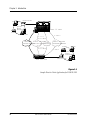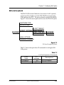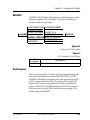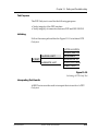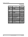
1
DSU III S2W
Data Service Unit
USER MANUAL
61200.015L2-1B
October 1995
Trademarks:
DATAPATH is a registered trademark of CAE electronics and is used by Northern
Telecom under license.
Hayes is a registered trademark of Hayes Microcomputer Products, Inc.
901 Explorer Boulevard
P.O. Box 070020
Huntsville, AL 35807
Phone: (205) 971-8000
Fax: (205) 971-8699
© 1995 ADTRAN, Inc.
All rights reserved.
Printed in USA.
FCC regulations require that the following information be provided in this manual:
1. This equipment complies with Part 68 of the FCC rules. On the bottom of the
equipment housing is a label that shows the FCC registration number and Ringer
Equivalence Number (REN) for this equipment. If requested, provide this information to
the telephone company.
2. If this equipment causes harm to the telephone network, the telephone company may
temporarily discontinue service. If possible, advance notification is given, otherwise,
notification is given as soon as possible. The telephone company will advise the
customer of the right to file a complaint with the FCC.
3. The telephone company may make changes in its facilities, equipment, operations, or
procedures that could affect the proper operation of this equipment; advance notification
and the opportunity to maintain uninterrupted service is given.
4. If experiencing difficulty with this equipment, please contact ADTRAN for repair and
warranty information. The telephone company may require this equipment to be
disconnected from the network until the problem is corrected, or it is certain the
equipment is not malfunctioning.
5. This unit contains no user serviceable parts.
6. An FCC compliant telephone cord with a modular plug is provided with this equipment.
This equipment is designed to be connected to the telephone network or premises
wiring using an FCC compatible modular jack, which is Part 68 compliant.
7. The following information may be required when applying to the local telephone
company for leased line facilities:
Service
Type
2.4 kbps Digital Interface
4.8 kbps Digital Interface
9.6 kbps Digital Interface
56 kbps Digital Interface
DigitalFacility
Interface Code
ServiceOrder
Code
Network
Jacks
04DU5-24
04DU5-48
04DU5-96
04DU5-56
6.0F
6.0F
6.0F
6.0F
RJ-48S
RJ-48S
RJ-48S
RJ-48S
FEDERALCOMMUNICATIONSCOMMISSION
RADIOFREQUENCYINTERFERENCESTATEMENT
This equipment has been tested and found to comply with the limits for a Class A digital device,
pursuant to Part 15 of the FCC Rules. These limits are designed to provide reasonable protection
against harmful interference when the equipment is operated in a commercial environment. This
equipment generates, uses, and can radiate radio frequency energy and, if not installed and used in
accordance with the instruction manual, may cause harmful interference to radio frequencies.
Operation of this equipment in a residential area is likely to cause harmful interference in which case
the user will be required to correct the interference at his own expense.
Shielded cables must be used with this unit to ensure compliance with Class A FCC limits.
Change or modifications to this unit not expressly approved by the
party responsible for compliance could void the user's authority to
operate the equipment.
CANADIAN EMISSIONS REQUIREMENTS
This digital apparatus does not exceed the Class A limits for radio noise emissions from
digital apparatus as set out in the interference-causing equipment standard entitled
“Digital Apparatus," ICES-003 of the Department of Communications.
Cet appareil nuerique respecte les limites de bruits radioelectriques applicables aux
appareils numeriques de Class A prescrites dans la norme sur le materiel brouilleur:
“Appareils Numeriques,” NMB-003 edictee par le ministre des Communications.
CANADIAN EQUIPMENT LIMITATIONS
Notice: The Canadian Industry and Science Canada label identifies certified
equipment. This certification means that the equipment meets certain telecommunications network protective, operational, and safety requirements. The Department does not guarantee the equipment will operate to the user's satisfaction.
Before installing this equipment, users should ensure that it is permissible to be
connected to the facilities of the local telecommunications company. The equipment must also be installed using an acceptable method of connection. In some
cases, the company's inside wiring associated with a single line individual service
may be extended by means of a certified connector assembly (telephone extension
cord). The customer should be aware that compliance with the above conditions
may not prevent degradation of service in some situations.
Repairs to certified equipment should be made by an authorized Canadian maintenance facility designated by the supplier. Any repairs or alterations made by the
user to this equipment, or equipment malfunctions, may give the telecommunications company cause to request the user to disconnect the equipment.
Users should ensure for their own protection that the electrical ground connections
of the power utility, telephone lines and internal metallic water pipe system, if
present, are connected together. This precaution may be particularly important in
rural areas.
Caution: Users should not attempt to make such connections themselves, but
should contact the appropriate electric inspection authority, or an electrician, as
appropriate.
The Load Number (LN) assigned to each terminal device denotes the percentage of
the total load to be connected to a telephone loop which is used by the device, to
prevent overloading. The termination on a loop may consist of any combination of
devices subject only to the requirement that the total of the Load Numbers of all
devices does not exceed 100.
Table of Contents
Table of Contents
Table of Contents
Chapter 1. Introduction
Product Overview .................................................................................................................... 1
General Datapath Description ................................................................................................ 3
Warranty and Customer Service ............................................................................................ 4
Chapter 2. Installation
Unpack, Inspect, Power Up ..................................................................................................... 5
Receipt Inspection ............................................................................................................ 5
Equipment Provided.................................................................................................. 5
Equipment Sold Separately ....................................................................................... 5
Power Up ........................................................................................................................... 6
Network Interface Connection ............................................................................................... 7
DTE Data Connection/Primary DTE ..................................................................................... 8
Dialport Connection .............................................................................................................. 10
Configuration ......................................................................................................................... 11
Configuration Methods .................................................................................................. 11
Front Panel ...................................................................................................................... 11
AT Commands ................................................................................................................ 12
V.25 bis Commands ....................................................................................................... 13
SDLC/HDLC Option .............................................................................................. 13
Character Format .............................................................................................. 13
Command Structure ......................................................................................... 13
Bi-Sync Option ......................................................................................................... 13
Character Format .............................................................................................. 13
Command Structure ......................................................................................... 13
Asynchronous Option ............................................................................................. 14
Character Format .............................................................................................. 14
Command Structure ......................................................................................... 14
Command Descriptions .......................................................................................... 14
Syntax and Possible Responses .............................................................................. 15
CIC (Connect Incoming Call) ......................................................................... 15
CNL (Configuration Local) ............................................................................. 15
Switched 56 Operation ........................................................................................... 15
CRN (Call Request with Number) .................................................................. 15
CRS (Call Request Using Stored Number) .................................................... 16
DIC (Disregard Incoming Call) ....................................................................... 16
61200.015L2-1
DSU III S2W User Manual
i
Table of Contents
PRN (Program Number) .................................................................................. 16
RLN (Request List of Numbers) ..................................................................... 17
Chapter 3. Operation
Menu Structure ...................................................................................................................... 19
LCD Display of the Main Menu ...................................................................... 19
Main Menu ..................................................................................................................... 20
Status ................................................................................................................. 20
Test ..................................................................................................................... 20
Configuration (CONFIG) ................................................................................ 20
Dial ..................................................................................................................... 20
Basic Menu Travel ........................................................................................................... 21
Front Panel .............................................................................................................................. 23
LCD Window .................................................................................................... 23
Enter .................................................................................................................. 23
Numeric Keypad ............................................................................................... 23
Shift .................................................................................................................... 23
Quick ................................................................................................................. 24
Cancel ................................................................................................................ 24
Up and Down Arrows ...................................................................................... 24
LED Description ............................................................................................... 24
Rear Panel ............................................................................................................................... 25
Chapter 4. Configuration Overview
Local Configuration ............................................................................................................... 27
Chapter 5. Configuring Network Options
Network Options ................................................................................................................... 31
Echo Cancel ..................................................................................................................... 31
Adapt ................................................................................................................................ 33
Volume Control .............................................................................................................. 34
Chapter 6. Configuring DTE Options
DTE Options ........................................................................................................................... 35
DTE Rate .......................................................................................................................... 35
Connector Type .............................................................................................................. 37
Data Format ..................................................................................................................... 38
DTE Command Option .................................................................................................. 39
Transmit Clock ............................................................................................................... 41
CS Options ...................................................................................................................... 43
ii
DSU III S2W User Manual
61200.015L2-1
Table of Contents
CD Options ..................................................................................................................... 45
TR Options ...................................................................................................................... 46
SR Options....................................................................................................................... 47
Chapter 7. Configuring Test Options
Test Options ........................................................................................................................... 49
Test Timeout ................................................................................................................... 49
Remote Digital Loopback ............................................................................................... 50
EIA Local Loopback ....................................................................................................... 51
EIA Remote Loopback .................................................................................................... 52
Chapter 8. Configuring Dial Options
Dial Options ........................................................................................................................... 53
Phone Number ................................................................................................................ 53
Edit SC# ........................................................................................................................... 54
Edit AD# .......................................................................................................................... 55
Auto Answer .................................................................................................................... 55
RS366 EON ..................................................................................................................... 56
Ring Again ....................................................................................................................... 57
Chapter 9. Manual Command
Manual Command ................................................................................................................. 59
Chapter 10. Dial Selection
Dial Options ........................................................................................................................... 63
Dial Stored # .................................................................................................................... 63
Enter Dial # ..................................................................................................................... 64
Speed Call ........................................................................................................................ 65
Auto Dial .......................................................................................................................... 66
Chapter 11. Testing and Troubleshooting
Test Overview ......................................................................................................................... 67
Initiating a Test ............................................................................................................... 68
Test Status Display .......................................................................................................... 69
Exiting a Test ................................................................................................................... 69
Troubleshooting ..................................................................................................................... 71
Messages from the DSU/CSU ....................................................................................... 71
Troubleshooting New Installs ........................................................................................ 73
Test Sequence for Troubleshooting New Installs or Existing Circuits ............... 74
Local Unit Diagnostics .......................................................................................................... 75
DTE & Loop (LL) ........................................................................................................... 76
61200.015L2-1
DSU III S2W User Manual
iii
Table of Contents
Test Description ....................................................................................................... 76
Test Purpose ............................................................................................................. 76
Initiating ................................................................................................................... 77
Interpreting Test Results ......................................................................................... 77
Loop Only (RT) .............................................................................................................. 78
Test Purpose ............................................................................................................. 78
Initiating ................................................................................................................... 78
Interpreting Test Results ......................................................................................... 79
DTE Only ......................................................................................................................... 80
Test Purpose ............................................................................................................. 81
Initiating ................................................................................................................... 81
Interpreting Test Results ......................................................................................... 81
DTE With Test Pattern ................................................................................................... 82
Test Purpose ............................................................................................................. 82
Initiating ................................................................................................................... 82
Interpreting Test Results ......................................................................................... 83
Test Pattern ...................................................................................................................... 84
Test Purpose ............................................................................................................. 84
Initiating ................................................................................................................... 85
Interpreting Test Results ......................................................................................... 85
Self Test ............................................................................................................................ 86
Test Purpose ............................................................................................................. 86
Initiating ................................................................................................................... 86
Interpreting Test Results ......................................................................................... 86
Remote Unit Diagnostics ................................................................................................ 87
Test Purpose ............................................................................................................. 88
Initiating ................................................................................................................... 88
Test Results .............................................................................................................. 88
Interpreting Test Results ......................................................................................... 88
Chapter 12. Status Selection
Status Display ......................................................................................................................... 89
DSU Operational Status ................................................................................................. 90
Data Mode ......................................................................................................... 90
Network Status ................................................................................................................ 90
Incoming Call/DTR Active ............................................................................... 90
Data Mode/Loop is Normal ............................................................................ 90
Idle/Loss of TCM Sync .................................................................................... 90
DTE Rate .......................................................................................................................... 90
DTE 56K Sync/Tx Clk Norm .......................................................................... 90
iv
DSU III S2W User Manual
61200.015L2-1
Table of Contents
DTE Clock ....................................................................................................................... 90
DTE Control Leads and Status ...................................................................................... 91
Appendix A. AT Commands .............................................................................................. 93
Appendix B. Default Configuration Profiles
Default Configuration Profiles .............................................................................................. 95
Profile 1 ............................................................................................................. 95
Profile 2 ............................................................................................................. 95
Profile 3 ............................................................................................................. 95
Profile 4 ............................................................................................................. 95
Appendix C. DSU to Modem Interconnect
Modem Tail Circuit Application ........................................................................................... 99
Appendix D. EIA-232 Connector
56 and 64 kbps Application ................................................................................................ 101
Appendix E. Specifications Summary
Specifications and Features ................................................................................................. 103
Glossary ............................................................................................................................... 105
Index ..................................................................................................................................... 111
List of Tables
Table 2-A Pin Assignments for Telco Connector .............................................................. 7
Table 2-B Pin Assignments for Primary EIA-232 Connector ........................................... 8
Table 2-C Pin Assignments for Primary V.35 Connector ................................................. 9
Table 2-D Pin Assignments for DIALPORT Connector .................................................. 10
Table 5-A Echo Cancel Commands ................................................................................. 32
Table 5-B Adapt Commands ............................................................................................. 33
Table 5-C Volume Level Commands ................................................................................ 34
Table 6-A DTE Rate AT Commands ................................................................................. 36
Table 6-B Data Format Commands .................................................................................. 38
Table 6-C DTE Command Descriptions .......................................................................... 4 0
Table 6-D Transmit Clock AT Commands ....................................................................... 41
Table 6-E CS Options AT Commands ............................................................................. 43
Table 6-F Short and Long Delays at Different Operating Speeds ................................. 44
Table 6-G CD Options AT Commands ............................................................................ 45
Table 6-H TR Options AT Commands ............................................................................. 46
Table 6-I
SR Options AT Commands ............................................................................. 47
61200.015L2-1
DSU III S2W User Manual
v
Table of Contents
Table 7-A
Table 7-B
Table 7-C
Table 7-D
Table 8-A
Table 8-B
Table 8-C
Table 8-D
Table 8-E
Table 9-A
Table 10-A
Table 10-B
Table 10-C
Table 10-D
Table 11-A
Table 11-B
Table 11-C
Table 11-D
Table 11-E
Table A-A
Table B-A
Test Timeout AT Commands ........................................................................... 50
Remote Digital Loopback AT Commands ...................................................... 50
EIA Local Loopback AT Commands ............................................................... 51
EIA Remote Loopback AT Commands ........................................................... 52
AT Command for Storing Phone Numbers .................................................... 54
AT Commands for Editing Speed Call Numbers ........................................... 54
AT Command for Auto Dialing ....................................................................... 55
At Command for Auto Answer ........................................................................ 56
At Commands for Ring Again ......................................................................... 57
Manual Commands .......................................................................................... 61
AT Command for Dialing Stored Numbers .................................................... 64
AT Command for Dialing a Number .............................................................. 65
AT Command for Speed Calling ..................................................................... 65
AT Command for Auto Dial ............................................................................. 66
Messages from the DSU/CSU ......................................................................... 72
Troubleshooting New Installs ......................................................................... 73
Test AT Commands .......................................................................................... 75
DTE with Test Pattern Commands ................................................................. 75
Remote Tests and AT Commands ................................................................... 87
AT Commands .................................................................................................. 93
Default Configuration Profiles ........................................................................ 96
List of Figures
Figure 1-1 Sample Point-to-Point Application for DSU III S2W ....................................... 2
Figure 3-1 Example of Basic Menu Travel ........................................................................ 22
Figure 3-2 DSU III S2W Front View ................................................................................. 23
Figure 3-3 DSU III S2W Rear View ................................................................................... 25
Figure 4-1 Complete Configuration Menu ....................................................................... 29
Figure 5-1 Setting Echo Cancel Options .......................................................................... 32
Figure 5-2 Enabling/Disabling Adapt ............................................................................... 33
Figure 5-3 Adjusting the Volume Level ............................................................................. 34
Figure 6-1 DTE Rates .......................................................................................................... 36
Figure 6-2 Selecting the Connector Type ......................................................................... 37
Figure 6-3 Selecting Asynchronous or Synchronous Data Format................................. 38
Figure 6-4 Selecting DTE Command Option ................................................................... 39
Figure 6-5 Transmit Clock Options .................................................................................. 41
Figure 6-6 Selecting CS Options ....................................................................................... 43
Figure 6-7 Selecting CD Options ...................................................................................... 45
Figure 6-8 Selecting TR Options ....................................................................................... 46
Figure 6-9 Setting SR Options ........................................................................................... 47
vi
DSU III S2W User Manual
61200.015L2-1
Table of Contents
Figure 7-1 Setting Test Timeout Option ........................................................................... 49
Figure 7-2 Remote Digital Loopback ................................................................................ 50
Figure 7-3 EIA Local Loopback Options .......................................................................... 51
Figure 7-4 EIA Remote Loopback Options ...................................................................... 52
Figure 8-1 Editing Stored Phone Numbers ...................................................................... 53
Figure 8-2 Editing Speed Call Numbers ........................................................................... 54
Figure 8-3 Editing Auto Dial Numbers ............................................................................. 55
Figure 8-4 Enabling/Disabling the Auto Answer Function ............................................. 56
Figure 8-5 Selecting RS366 EON Options ........................................................................ 56
Figure 8-6 Selecting Ring Again Options ......................................................................... 57
Figure 9-1 Manual Command ............................................................................................ 59
Figure 10-1 Dial Options Menu ........................................................................................... 63
Figure 10-2 Path to Storing Numbers ................................................................................. 64
Figure 10-3 Entering Dial Number ...................................................................................... 64
Figure 10-4 Path to Speed Calling ....................................................................................... 65
Figure 10-5 Path to Auto Dialing ......................................................................................... 66
Figure 11-1 Normal Operation Before Initiating Loopback Test .................................... 67
Figure 11-2 Initiating a Test ............................................................................................... 68
Figure 11-3 Sample Test Status Displays ........................................................................... 69
Figure 11-4 Complete Test Menu ....................................................................................... 70
Figure 11-5 DTE & Loop Test ............................................................................................ 76
Figure 11-6 Initiating a DTE & Loop Test ........................................................................ 77
Figure 11-7 Loop Only Test ............................................................................................... 78
Figure 11-8 Initiating a Loop Only Test ............................................................................ 78
Figure 11-9 DTE Only Test Diagram ................................................................................. 80
Figure 11-10 Initiating a DTE Only Test ............................................................................. 81
Figure 11-11 DTE with Test Pattern .................................................................................... 82
Figure 11-12 Initiating a DTE Test with Test Pattern ......................................................... 83
Figure 11-13 Test Pattern Only ............................................................................................ 84
Figure 11-14 Initiating a Test Using a Test Pattern ............................................................ 85
Figure 11-15 Initiating a Self Test ........................................................................................ 86
Figure 11-16 V.54 Remote Digital Loopback with Test Pattern ........................................ 87
Figure 11-17 Initiating a Remote Test ................................................................................. 88
Figure 12-1 Example of Status Displays ............................................................................. 89
Figure C-1 DSU to Modem Interconnect .......................................................................... 99
Figure D-1 EIA-232 Connector ......................................................................................... 101
61200.015L2-1
DSU III S2W User Manual
vii
Table of Contents
viii
DSU III S2W User Manual
61200.015L2-1
Chapter 1. Introduction
Chapter 1
Introduction
PRODUCT OVERVIEW
The ADTRAN Data Service Unit III Switched 2-Wire (DSU III
S2W) provides a reliable, high speed data connection from a
customer’s Data Terminal Equipment (DTE) through 2-wire
Switched 56 (SW56) network lines. This type of SW56 service is
generally referred to as DATAPATH®. The DSU III S2W supports
both synchronous and asynchronous data communication over
SW56 networks.
The DSU III S2W provides both V.35 and EIA-232 electrical and
physical DTE interfaces to accommodate a variety of applications.
A second DB-25 labeled EIA-366/232 provides an EIA-366 parallel
dialing interface. The unit features a receiver capability which
permits operation over loops 14,000 ft on 26 AWG. Figure 1-1
shows a sample point-to-point application for the DSU III S2W.
61200.015L2-1
DSU III S2W User Manual
1
Chapter 1. Introduction
BRIDGE/ROUTER
DSU III AR
DSU III AR
DSU III AR
DSU III AR DSU III S4W
DSU III S4W
DSU III S4W DSU III S4W DSU III DBU
DSU III DBU DSU III DBU
-5V
CHEC
K
-12V
+5V
CHEC
K
-5V
-12V
+12V
POWER SUPPLY
+5V
POWER SUPPLY
SHELF
+12V
PCs
DSU III DBU
DSU S2W
DSU S2W
DSU S2W
CONTROLLER
Local
Area
Network
RS
RS
RS
RS
RS
RS
RS
RS
RS
RS
RS
RS
RS
RS
RS
CS
CS
CS
CS
CS
CS
CS
CS
CS
CS
CS
CS
CS
CS
CS
TD
TD
TD
TD
TD
TD
TD
TD
TD
TD
TD
TD
TD
TD
TD
RD
RD
RD
RD
RD
RD
RD
RD
RD
RD
RD
RD
RD
RD
RD
CD
CD
CD
CD
CD
CD
CD
CD
CD
CD
CD
CD
CD
CD
CD
ALM
ALM
ALM
ALM
ALM
ALM
ALM
ALM
ALM
ALM
ALM
ALM
ALM
ALM
ALM
DTE
DTE
DTE
DTE
DTE
DTE
DTE
DTE
DTE
DTE
DTE
DTE
DTE
DTE
DTE
LOOP
LOOP
LOOP
LOOP
LOOP
LOOP
LOOP
LOOP
LOOP
LOOP
LOOP
LOOP
LOOP
LOOP
LOOP
RDL
RDL
RDL
RDL
RDL
RDL
RDL
RDL
RDL
RDL
RDL
RDL
RDL
RDL
PTRN
PTRN
PTRN
PTRN
PTRN
PTRN
PTRN
PTRN
PTRN
PTRN
PTRN
PTRN
PTRN
PTRN
ERROR
ERROR
ERROR
ERROR
ERROR
ERROR
ERROR
ERROR
ERROR
ERROR
ERROR
ERROR
ERROR
ERROR
SELECT
SELECT
SELECT
SELECT
SELECT
SELECT
SELECT
SELECT
SELECT
SELECT
SELECT
SELECT
SELECT
SELECT
TEST
TEST
TEST
TEST
TEST
TEST
TEST
TEST
TEST
TEST
TEST
TEST
TEST
TEST
TEST
2
3
4
5
6
7
8
9
10
12
13
14
15
16
RDL
PTRN
ERROR
DIALMATE
DIAL
STATUS
CANCEL
TEST
CONFIG
ENTER
1
2
3
4
5
6
8
9
7
0
1
11
SELECT
SMART 16 SHELF
PRINTER
SERVER
V.32bis
2 or 4
wire SW56
DEDICATED PUBLIC SWITCHED ISDN
DIGITAL NETWORKNETWORK
PRIVATE NETWORK
PUBLIC SWITCHED
TELEPHONE NETWORK
PRINTER
2 or 4
wire SW56
PC
V.32bis
DSU III DBU
RS
CS
TD
RD
CD
ENTER
ALM TST
A
1
D
4
B
2
E
5
7
8
SHIFT
CANCEL
*
0
C
3
F
6
Local
Area
Network
9
SHIFT
#
DSU III S2W
BRIDGE/ROUTER
SERVE
Figure 1-1
Sample Point-to-Point Application for DSU III S2W
2
DSU III S2W User Manual
61200.015L2-1
Chapter 1. Introduction
GENERAL DATAPATH DESCRIPTION
DATAPATH is a 2-wire switched digital service offered by the local
service provider. The services are generally provided by the
Northern Telecom DMS/SL 100 family of Central Office switches.
DATAPATH is always switched, which allows the customer to pay
for high speed data transfer only when a call is active. The dial-up
service is delivered by a 2-wire local loop up to 14,000 feet long on
26 AWG. The DSU III S2W uses a bipolar return-to-zero type of
signal in a ping-pong (Time Compression Multiplexing) format.
Another basic component of DATAPATH technology is T-Link rate
adaption protocol which adapts user data rates into network
transport bit streams of 56 or 64 kbps. The units will connect and
negotiate the most efficient rate at which to send data. The
ADTRAN DSU III S2W can communicate and rate adapt with any
T-Link compatible device. It can also interface with non T-Link
compatible devices at 56 or 64 kbps, allowing the user to place a
call to a 4-wire SW56 network or ISDN device.
61200.015L2-1
DSU III S2W User Manual
3
Chapter 1. Introduction
WARRANTY AND CUSTOMER SERVICE
ADTRAN will replace or repair this product within five years from
the date of shipment if it does not meet its published specifications
or fails while in service. For detailed warranty, repair, and return
information refer to the ADTRAN Equipment Warranty and Repair
and Return Policy Procedure.
Return Material Authorization (RMA) is required prior to returning
equipment to ADTRAN.
For service, RMA requests, or further information, contact one of
the numbers listed on the inside back cover of this manual.
4
DSU III S2W User Manual
61200.015L2-1
Chapter 2. Installation
Chapter 2
Installation
UNPACK, INSPECT, POWER UP
Receipt Inspection
Carefully inspect the DSU III S2W for any shipping damages. If
damage is suspected, file a claim immediately with the carrier and
contact ADTRAN Customer Service. If possible, keep the original
shipping container for use in shipping the DSU III S2W for repair
or for verification of damage during shipment.
Equipment Provided
The following items are included in ADTRAN shipments of the
DSU III S2W:
• DSU III S2W unit
• A 6-position modular to 6-position modular line interface cable
• The user manual
Equipment Sold Separately
The customer must provide an EIA-232 interface cable with
standard 25-pin male D-type connectors (Cannon or Cinch DB19604-432) or V.35 cable, and a cable for the EIA-366 Dialport if
used.
61200.015L2-1
DSU III S2W User Manual
5
Chapter 2. Installation
Power Up
Each DSU unit is provided with a captive eight-foot power cord,
terminated by a three-prong plug which connects to a grounded
115 VAC power receptacle. A telco connector is also provided for
interface to the network.
Power to the DSU must be provided from a grounded 115 VAC, 60 Hz
receptacle.
6
DSU III S2W User Manual
61200.015L2-1
Chapter 2. Installation
NETWORK INTERFACE CONNECTION
The DSU III S2W has a six-position modular jack labeled TELCO.
The connector is used for connecting to the network when the unit
is configured for either dedicated or switched operation. The pin
assignments for the telco connector are listed in Table 2-A.
Table 2-A
Pin Assignments for Telco Connector
Pin
1
2
3
4
5
6
61200.015L2-1
Name
T
R
Description
Not used
Not used
Network interface, tip
Network interface, ring
Not used
Not used
DSU III S2W User Manual
7
Chapter 2. Installation
DTE DATA CONNECTION/PRIMARY DTE
The primary DTE should be connected to either the EIA-232 DTE
connector or the CCITT V.35 DTE connector. The maximum cable
lengths recommended are 50 feet for the EIA-232 and 100 feet for
the CCITT V.35. The pin assignments for the connectors are listed
in Tables 2-B and 2-C.
The V.35 connector is recommended for use with data rates above
19.2 kbps. The EIA-232 connector works up to 56 kbps with a low
capacitance cable or with the external transmit clock option
selected. The primary DTE rate is configured from the front panel.
The primary DTE can operate in asynchronous or synchronous
modes.
To prevent possible radio frequency interference emissions, a shielded
cable is required.
Table 2-B
Pin Assignments for Primary EIA-232 Connector
Pin
1
2
3
4
5
6
7
8
9
10
15
17
18
20
21
22
24
25
8
EIA
AA
BA
BB
CA
CB
CC
AB
CF
DB
DD
CD
CE
DA
-
Description
Protective Ground (PG)
Transmit Data (TD)
Receive Data (RD)
Request to Send (RS)
Clear to Send (CS)
Data Set Ready (SR)
Signal Ground (SG)
Received Line Signal Detector (C
+12 Test Point
-12 Test Point
Transmit Clock (TC)
Receive Clock (RC)
Local Loopback (LL)
Data Terminal Ready (TR)
Remote Loopback (RL)
Ring Indicator (RI)
External TX Clock (ETC)
Test Indicator (TI)
DSU III S2W User Manual
61200.015L2-1
Chapter 2. Installation
Table 2-C
Pin Assignments for Primary V.35 Connector
Pin
A
B
C
D
E
F
H
J
L
N
R
T
V
X
P
S
Y
AA
U
W
NN
61200.015L2-1
CCITT
101
102
105
106
107
109
104
104
115
115
103
103
114
114
113
113
-
Description
Protective Ground (PG)
Signal Ground (SG)
Request to Send (RS)
Clear to Send (CS)
Data Set Ready (SR)
Received Line Signal Detector (C
Data Terminal Ready (TR)
Ring Indicator (RI)
Local Loopback (LL)
Remote Loopback (RL)
Received Data (RD-A)
Received Data (RD-B)
Receiver Signal Element Timing (
Receiver Signal Element Timing (
Transmitted Data (SD-A)
Transmitted Data (SD-B)
Transmitter Signal Element Timin
Transmitter Signal Element Timin
External TX Signal Element (SCX
External TX Signal Element (SCX
Test Indicator (TI)
DSU III S2W User Manual
9
Chapter 2. Installation
DIALPORT CONNECTION
If used, the DTE dialing interface should be connected to the EIA366/232 connector. The DIALPORT connector services an EIA-366
Type III interface. The pinout for the connector when used as EIA366 is shown in Table 2-D.
Table 2-D
Pin Assignments for DIALPORT Connector
Pin
1
2
3
4
5
6
7
13
14
15
16
17
18
19
22
8 thru 12
20, 21, 2
thru 25
10
EIA
Shield
DPR
ACR
CRQ
PND
PWI
SG
DSC
NB1
NB1
NB4
NB8
RC
SC
DLO
NC
I/O
I/O
I
O
I
O
O
I/O
O
I
I
I
I
O
I
O
N/A
DSU III S2W User Manual
Description
Shield for cable
Digit Present
Abandon Call and Ret
Call Request
Present Next Digit
Power Indicator
Signal Ground
Distant Station Conne
Digit LSB
Digit Bit 2
Digit Bit 3
Digit MSB
Receive Common
Send Common
Data Line Occupied
No Connection
61200.015L2-1
Chapter 2. Installation
CONFIGURATION
The DSU III S2W contains four different user profiles (sets of
configurations options) that are stored in read only memory. These
profiles are listed in the appendix Default Configuration Profiles. The
unit is shipped from the factory with profile 1 (default configuration) loaded into the nonvolatile configuration memory. If profile 1
matches the desired system requirements, then no additional
configuration is required to put the unit into service. If profile 1
does not match the desired system requirements, modify the
default configuration or select another profile more closely matching the desired configuration and modify.
When a new profile is loaded or the existing profile is modified, it
is stored in the nonvolatile configuration memory. The DSU III
S2W is then configured with that profile every time power is
turned on or reset. See the chapter Manual Command for information on loading default configuration profiles.
Configuration Methods
The DSU III S2W provides three methods for local configuration:
front panel, AT commands (in-band or via control port), and V.25
bis.
Front Panel
The Front Panel provides access to all operation parameters of the
DSU III S2W through a multi-level menu structure which begins
with the four-part Main menu.
STATUS - displays status of network and DTE interface
TEST controls local and remote testing
CONFIG - displays/changes current configuration parameters
DIAL provides manual dialing functions
61200.015L2-1
DSU III S2W User Manual
11
Chapter 2. Installation
AT Commands
The DSU III S2W can be configured and controlled with in-band
AT commands from an asynchronous DTE port just as modems
are.
To exit the data mode and enter the command mode, the asynchronous DTE device must transmit a proper escape sequence or three
pluses (+++) to the DSU III S2W. A specified time delay must
occur between the last data character and the first escape sequence
character. This is the guard time delay, and it can be changed by
writing a value to the S12 register. The default value for the guard
time is one second. For a valid escape sequence to occur, the DTE
must transmit the escape code character three times in succession
with delay between each character being less than the guard time.
Once the command mode is entered, AT commands can be
transmitted to the DSU III S2W to configure most of the options or
initiate tests to check both the DSU III S2W and the network
connections. All command lines must begin with the AT character
set in either capital or lower case letters.
The command line may contain a single command or a series of
commands after the AT attention code. When a series of commands is used, the individual commands may be separated with
spaces for readability. The maximum length for a command line is
40 characters. Each command line is executed by the DSU III S2W
upon receipt of a terminating character. The default terminating
character is a carriage return (ASCII 013), but it can be changed by
writing a different value to register S3.
Before the terminating character is transmitted, the command line
can be edited by using the backspace character (ASCII 008) to
erase errors so the proper commands can be entered. Valid AT
commands for the DSU III S2W are listed in the appendix AT
Commands.
12
DSU III S2W User Manual
61200.015L2-1
Chapter 2. Installation
V.25 bis Commands
When configured for the V.25 bis option, the DSU III S2W accepts
in-band dialing and configuration commands from both synchronous and asynchronous DTE ports.
The V.25 bis option supports the following protocols:
• SDLC/HDLC
• Bi-Sync
• Asynchronous
SDLC/HDLC Option
Character Format
• Data bits - 8
• Parity bit - Ignored
Command Structure
[F][A][C][V.25 bis COMMAND][FCS][F]
The address field [A] is FFH. The control field [C] is set to 13H
except for cases of multi-frame responses. For this case, the
control field is set to 03H in all but the last frame. The 03H in the
control field indicates that other frames are to follow while the 13H
in the control field indicates the final frame.
Bi-Sync Option
Character Format
• Data bits - 7
• Parity bit - Odd
Command Structure
[SYN][SYN][STX][V.25 bis COMMAND][ETX]
61200.015L2-1
DSU III S2W User Manual
13
Chapter 2. Installation
Asynchronous Option
Character Format
• Start bit - 1
• Data bits - 7
• Parity bit - Even
• Stop bit - 1
Command Structure
[V.25 bis COMMAND][CR][LF]
Command Descriptions
The ADTRAN V.25 bis command set is a subset of the CCITT
V.25 bis command set. In addition to the CCITT commands
supported, ADTRAN has added configuration commands for local
DSUs. The ADTRAN V.25 bis command set follows:
CIC
CNL
CRN
CRS
DIC
PRN
RLN
Connect incoming call
Configuration local
Call request with number
Call request using stored number
Disregard incoming call
Program number
Request list of numbers
The following list contains possible responses to V.25 bis commands:
VAL
INV
CFIET
CFIDE
CFINS
INVCU
INVPS
INVPV
INC
CNX
14
Valid V.25 command processed
An invalid command detected
Call failed on switched network - busy detected
Call failed on switched network - no wink detected
Call failed - no dial string in specified register
Unknown command detected
Invalid parameter syntax
Invalid parameter value
Incoming call
Call connected
DSU III S2W User Manual
61200.015L2-1
Chapter 2. Installation
If verbose (wordy) responses are disabled (ATV0), the following list
of three-character responses are the only ones returned:
VAL
INV
CFI
INC
CNX
Valid V.25 command processed
Invalid command received
Call failed
Incoming call
Call connected
Syntax and Possible Responses
CIC (Connect Incoming Call)
This command causes the DSU to go on-line. There are no parameters associated with this command. Possible indications include
VAL, CNX, and CFIxx.
CNL (Configuration Local)
This command is used to pass AT commands to the local modem
via the V.25 bis command processor. This allows the DSU III S2W
to be configured with AT commands via a synchronous interface.
The command has the following format:
CNL AT[ONE OR MORE AT COMMANDS]
Responses to CNL commands are returned in the data format
currently configured. Possible responses include VAL and INVn.
Switched 56 Operation
CRN (Call Request with Number)
When the DSU III S2W is configured for SW56 operation, the CRN
command causes the DSU to dial the supplied number. The
command's format follows:
CRN[NUMBER TO BE DIALED]
If no number is included in the command, the number stored in
dial register number 1 is dialed. If no number is provided and no
61200.015L2-1
DSU III S2W User Manual
15
Chapter 2. Installation
number is stored in dial register number 1, the DSU III S2W
responds with the call failure indication CFINS (Call Failure
Indication Not Stored). Possible responses include VAL, CNX, and
CFIxx.
CRS (Call Request Using Stored Number)
The CRS command causes the DSU III S2W to dial the number
stored in the specified register. The format of this command is as
follows:
CRS
[OPTIONAL SPACE][REGISTER NUMBER 1-10]
If this command is issued without the register number parameter,
the INVPS (Invalid Parameter Syntax) response is issued. If this
command is issued and the register parameter is not in the valid
range for dialing registers, the INVPV (Invalid Parameter Value)
response is returned. Other responses include VAL, CNX, and
CFIxx.
DIC (Disregard Incoming Call)
This command causes the V.25 bis processor to return to command
mode even if there is an incoming call pending. This allows local
commands to be issued and incoming calls to be ignored. There
are no parameters associated with this command. The DSU
responds with VAL.
PRN (Program Number)
This command stores the supplied number into the specified
register. The command has the following format:
PRN
REGISTER NUMBER;[NUMBER TO BE STORED]
If this command is entered with no parameters, the INVPS response is returned. If no register number is included in the
command or if it is invalid, the INVPV response is returned. This
response is also returned if the number to be stored contains
invalid characters. The characters 1, 2, 3, 4, 5, 6, 7, 8, 9, 0, P, T,
and & are valid dial characters. If no digits are issued with this
command, the specified register is cleared. The DSU responds
with VAL.
16
DSU III S2W User Manual
61200.015L2-1
Chapter 2. Installation
RLN (Request List of Numbers)
This command causes the DSU III S2W to return the number
stored in the specified register. The format of this command
follows:
RLN
[REGISTER NUMBER]
If the register number is invalid, the INVPV response is returned.
When a correct register number is entered, the following response
is returned:
LSN
[REGISTER NUMBER];[NUMBER STORED]VAL
If no register number is present in the command, the DSU III S2W
responds with a list of all the registers and the stored numbers.
This list is followed by the VAL response.
61200.015L2-1
DSU III S2W User Manual
17
Chapter 2. Installation
18
DSU III S2W User Manual
61200.015L2-1
Chapter 3. Operation
Chapter 3
Operation
MENU STRUCTURE
The DSU III S2W uses a multilevel menu approach to access its
many features. All menu operations are displayed in the LCD
window.
The opening menu is the access point for all other operations.
There are four Main menu branches: Status, Test, Configuration
and Dial.
Each Main menu item has several functions and sub-menus to
identify and access specific parameters.
LCD Display of the Main menu
1=STATUS
3=CONFIG
2=TEST
4=DIAL
To choose an item, press the number on the keypad corresponding
with that item. That item will flash on and off to show that it is the
currently active choice. Pressing either the Up or Down Arrow
will deselect the current choice (it will stop flashing). Press the
Enter key to select the item.
61200.015L2-1
DSU III S2W User Manual
19
Chapter 3. Operation
Main Menu
The following paragraphs briefly describe the Main menu's four
branches. More detailed information is provided in the individual
chapters for each branch.
Status
Status is used to display all relevant information for the network
and DTE interfaces. It displays the current operating mode, loop
status, DTE data rate and format, and TR, SR, LL, and RL DTE
interface lead status. The display returns to the Status menu when
the front panel is not accessed. Refer to the chapter Status Selection
for more detailed information.
Test
Test is used to control local and remote testing. Select local or
remote testing, and select the type of test and test pattern when
required. For more information see the chapter, Testing and
Troubleshooting.
Configuration (CONFIG)
Configuration is used to select network and DTE operating parameters. This menu branch is divided into several chapters for easier
reference. The division includes a brief overview chapter followed
by a separate chapter for each of the five sub-menus of the
CONFIG branch: Configuring Network Options, Configuring DTE
Options, Configuring Test Options, Configuring Dial Options, and
Manual Command.
Dial
Dial provides dialing functions. Select a previously stored number,
key in a number to dial, or use the speed call and autodial functions which must be purchased from the telco provider. See the
chapter, Dial Selection, for more information.
20
DSU III S2W User Manual
61200.015L2-1
Chapter 3. Operation
Basic Menu Travel
Four function keys on the left side of the DSU III S2W keypad
allow the various menu branches to be entered, exited, and scrolled
through. The four function keys are defined below.
Enter
Up Arrow
Down Arrow
Cancel
selects an activated item
scrolls up the sub-menu items
scrolls down the sub-menu items
exits (back one level) from the current branch
of the menu
To choose a menu item, press the corresponding number or alpha
character on the keypad (press Shift to activate the alpha selections). The item flashes on and off to show it is the currently
selected (active) choice. Pressing either the Up or Down Arrow
scrolls through the available menu items. Pressing Enter selects
the flashing item.
The following example and Figure 3-1 illustrate how to select the
ECHO CANCEL option.
1. Select Configuration (CONFIG) by pressing 3, then press
Enter.
2. Use the Up and Down Arrows to view sub-menu items.
3. Choose an item on the sub-menu such as Network Options
(NETWORK OPT).
4. To select NETWORK OPT press 1, then press Enter.
5. To select ECHO CANCEL, press 1, then press Enter.
61200.015L2-1
DSU III S2W User Manual
21
Chapter 3. Operation
1=NETWORK OPT.
3=CONFIG2=DTE OPTIONS
3=TEST OPTIONS
4=DIAL OPTIONS
5=MANUAL COMMAND
1=ECHO CANCE
2=ADAPT
3=VOLUME CNTL
Figure 3-1
Example of Basic Menu Travel
22
DSU III S2W User Manual
61200.015L2-1
Chapter 3. Operation
FRONT PANEL
The DSU III S2W faceplate is shown in Figure 3-2.
DSU III S2W
RS
CS
TD
RD
ENTER
CD ALM TST
A
B
C
1
2
3
D
4
E
5
F
6
7
8
SHIFT
CANCEL
*
9
QUICK
0
#
Figure 3-2
DSU III S2W Front View
The following function descriptions apply to the stand alone S2W.
LCD Window
Displays menu items and messages in 2 lines by 16 characters.
Enter
Selects active menu items. To activate a menu item, press the
number of the item. When the menu item is flashing, press Enter
to select it. A sub-menu item is invoked or a configuration
parameter is set. The display of COMMAND ACCEPTED indicates
a valid operation.
Numeric Keypad
The numeric keypad contains the numbers 0 through 9 and alpha
characters A through F, which are used to activate menu items.
Numbers 0 through 9 are also used to enter parameters.
Shift
Alpha characters are entered by pressing Shift before each desired
character. To activate a menu item designated by an alpha character rather than a number, display the menu item using the Up and
Down Arrows, press Shift and then the letter. Press Enter to select
the item.
61200.015L2-1
DSU III S2W User Manual
23
Chapter 3. Operation
If a key is pressed without using Shift, the numbered item becomes
active instead of the alpha item. If this happens, repeat the correct
procedure.
Quick
During most operations, the Quick key returns the display to the
Main menu. During a test, the Quick key returns to the top of the
Test menu.
Cancel
The Cancel key stops the current activity and returns to the
previous menu. Repeat until the desired menu level is reached.
Up and Down Arrows
The Up and Down Arrows scroll through the sub-menu items
available in the current menu. Sub-menu items appear two at a
time in a circular or wrapping fashion. When the sub-menu items
are scrolled, they continuously appear from beginning to end in a
forward (Down Arrow) or reverse (Up Arrow) pattern.
LED Description
The DSU III S2W has seven LED indicators: RS, CS, TD, RD, CD,
ALM and TST. These LEDs are identified as follows:
RS:
CS:
TD:
RD:
CD:
ALM:
TST:
24
Request to Send
Clear to Send
Transmit Data
Receive Data
Carrier Detect
Alarm Indication
Test Mode
DSU III S2W User Manual
61200.015L2-1
Chapter 3. Operation
REAR PANEL
The rear panel contains three DTE connectors which provide
primary channel V.35 or EIA-232 and a Dialport (auxiliary EIA 366/232). A 6-pin telco jack, a captive power cord, and a power
switch are also located on the rear panel. Pin assignments for the
DTE and network connections are listed in the chapter Installation.
The DSU III S2W rear panel is shown in Figure 3-3.
1
2
ON
EIA 366/232
PRIMARY V.35
OFF
PRIMARY EIA-232
TELCO
115 VAC
60HZ .15A
3
4
1.
2.
3.
4.
5.
6.
5
6
Identification of Numbers
Item
Function
Auxiliary EIA-366/232 EIA-366/232 dialport
Power Switch
Used to turn power on or off
Telco Connection
Connection to the dedicated circuit
Primary EIA-232
DTE interface
Primary V.35
High speed digital data interface
115 VAC Connection
Power cord connection
Figure 3-3
DSU III S2W Rear View
61200.015L2-1
DSU III S2W User Manual
25
Chapter 3. Operation
26
DSU III S2W User Manual
61200.015L2-1
Chapter 4. Configuration Overview
Chapter 4
Configuration Overview
LOCAL CONFIGURATION
The Configuration menu consists of a group of five sub-menus
relating to a specific interface or function of the DSU III S2W that
requires setup.
1=Network Opt.
2=DTE Options
3=Test Options
4=Dial Options
5=Manual Command
Network Interface Parameters
DTE Interface Parameters
Unit Test Options
Unit Dialing Options
ADTRAN Specific Commands
The DSU III S2W contains four different user profiles (sets of
configurations options) that are stored in read only memory (see
the appendix, Default Configuration Profiles). The unit is shipped
from the factory with profile number 1 (default configuration)
loaded into the current (nonvolatile configuration) memory. If
profile 1 matches requirements for the system, then no additional
configuration is required to put the unit into service. If profile 1
does not match system requirements it can be modified, or one of
the other profiles that more closely matches the system requirements can be loaded into current memory. When a different
profile is loaded, or the existing profile is modified, it is stored in
the current (nonvolatile configuration) memory. The DSU III S2W
is then configured with that profile every time power is turned on
or until the unit is reset.
61200.015L2-1
DSU III S2W User Manual
27
Chapter 4. Configuration Overview
For detailed information on configuration see the chapters Configuring Network Options, Configuring DTE Options, Configuring Test
Options, Configuring Dial Options, and Manual Command.
A complete Configuration menu is shown in Figure 4-1.
28
DSU III S2W User Manual
61200.015L2-1
Chapter 4. Configuration Overview
(Fold Out of Complete Configuration Menu belongs here)
61200.015L2-1
DSU III S2W User Manual
29
Chapter 4. Configuration Overview
30
DSU III S2W User Manual
61200.015L2-1
Chapter 4. Configuration Overview
1=ECHO CANCEL
1=DISABLE
2=ENABLE ORIG.
3=ENABLE ANSW
4=ENABLE BOTH
1=NETWORK OPT.
1=DTE RATE
2=ADAPT
1=DISABLED
2=ENABLED
3=NO T-LINK 57.6
2=CONNECTOR TYPE
3=VOLUME CNTL
VOLUME LEVEL
(0-3):0
3=DATA FORMAT
4=DTE CMD OPTION
2=DTE OPTIONS
1=TEST TIMEOUT
ENTER TIMEOUT
(0=OFF) : 00 SEC
5=TRANSMIT CLOCK
1=DTE
2=DTE
3=DTE
4=DTE
5=DTE
6=DTE
7=DTE
8=DTE
9=DTE
1.2k
2.4k
4.8k
9.6k
19.2k
38.4k
48k
56k/57.6k
64k
1=RS-232
2=V.35
1=ASYNCHRONOUS
2=SYNCHRONOUS
3=TEST OPTIONS
1=NORMAL
2=EXTERNAL
1=FORCED ON
2=FOLLOWS RS
3=FOLLOWS CD
1=RDL IGNORED
2=RDL ACCEPTED
4=FOLLOWS RS+CD
3=EIA LLB EN/DIS 1=DISABLED
2=ENABLED
5=OFF WITH LOCD
7=CD OPTIONS
4=EIA RLB EN/DIS 1=DISABLED
2=ENABLED
8=TR OPTIONS
3=CONFIG
1=IGNORED
2=LEASED LINE
3=IDLE WHEN OFF
4=OFF>ON DIAL #1
5=OFF>ON DIAL #2
9=SR OPTIONS
STORED NUMBER TO
1=PHONE NUMBERSEDIT (1-10):
NNNNNNN
2=EDIT SC#
SPEED CALL # TO
EDIT (1-10):
NNNNNNN
3=EDIT AD #
NNNNNNN
4=AUTO ANSWER
1=DISABLED
2=ENABLED
5=RS366 EON
1=DISABLED
2=ENABLED
6=RING AGAIN
1=DISABLED
2=ENABLED
4=DIAL OPTIONS
5=MANUAL COMMANDCOMMAND:00
COMMAND:HH
VALUE:00
Figure 4-1
Complete Configuration Menu
61200.015L2-1
DSU III S2W User Manual
1=EVEN PARITY
2=MARK PARITY
3=ODD PARITY
4=NO PARITY
1=DISABLED
2=AT COMMAND SET
3=V.25 SYNC
4=V.25 BSC/ASYNC
5=V.25 SYNC (FLG)
6=CS OPTIONS
2=RDL EN/DIS
1=ASYNC 7 BITS
2=ASYNC 8 BITS
29
1=FORCED ON
2=NORMAL
3=OFF WITH LOCD
1=FORCED ON
2=OFF IDLE ONLY
3=OFF LOCD ONLY
4=OFF TEST ONLY
5=OFF TEST +IDLE
6=OFF TEST +LOCD
1=CS DELAY SHORT
2=CS DELAY LONG
1=CS DELAY SHORT
2=CS DELAY LONG
1=1 STOP BIT
2=2 STOP BITS
Chapter 5. Configuring Network Options
Chapter 5
Configuring Network Options
NETWORK OPTIONS
The NETWORK OPTIONS configuration parameters control the
loop operation of the DSU III S2W. Once a parameter is set,
Command Accepted is displayed briefly before returning to the
active menu.
Echo Cancel
The ECHO CANCEL option enables/disables a PCM encoded 2100
Hz tone transmitted for one half second that causes the digital
network to disable echo suppressors and echo cancellers so that
digital signals proceed unimpeded.
61200.015L2-1
DSU III S2W User Manual
31
Chapter 5. Configuring Network Options
1=DISABLE
2=ENABLE ORIG.
1=ECHO CANCEL3=ENABLE ANS
4=ENABLE BOTH
1=NETWORK OPT.
2=ADAPT
3=VOLUME CNTL
3=CONFIG2=DTE OPTIONS
3=TEST OPTIONS
4=DIAL OPTIONS
5=MANUAL COMMAND
Figure 5-1
Setting Echo Cancel Options
The default factory setting is ENABLE ANSW. The selections are
listed in Table 5-A with the equivalent AT commands that perform
the same configuration functions.
Table 5-A
Echo Cancel Commands
AT
Command
1=DISABLE
&L0
2=ENABLE ORIG
&L1
3=ENABLE ANSW
&L2
4=ENABLE BOTH
&L3
Front Panel
32
Description
Echo cancel disabled
Echo cancel on originate
Echo cancel on answer
Echo cancel on originate and an
DSU III S2W User Manual
61200.015L2-1
Chapter 5. Configuring Network Options
Adapt
The ADAPT option enables/disables the DSU to rate adapt to its far
end unit. Figure 5-2 shows the menu path used to enable or
disable ADAPT. The factory default setting is ENABLED.
The NO T-LINK 57.6 selection disables the T-link operation when 56K/
57.6K is selected for immediate connection to a non T-link far end unit.
1=ECHO CANCEL
3=CONFIG
1=NETWORK OPT.
2=DTE OPTIONS
3=TEST OPTIONS
4=DIAL OPTIONS
5=MANUAL COMMAND
1=DISABLED
2=ENABLED
3=NO T-LINK 57.6
2=ADAPT
3=VOLUME CNTL
Figure 5-2
Enabling/Disabling Adapt
Table 5-B shows the AT commands for this option.
Table 5-B
Adapt Commands
Front
AT
Description
Panel
Command
1=DISABLE
TL0
Disables Adapt
2=ENABLE
TL1
Enables Adapt
3=NO T-LINK 57.6 TL2
Disables T-Link operation w
56K/57.6K
61200.015L2-1
DSU III S2W User Manual
33
Chapter 5. Configuring Network Options
Volume Control
The VOLUME CNTL option allows the volume level to be adjusted.
Figure 5-3 shows the menu path for controlling the volume.
The factory default setting is OFF.
1=NETWORK OPT.
2=DTE OPTIONS
3=CONFIG3=TEST OPTIONS
4=DIAL OPTIONS
5=MANUAL COMMAND
1=ECHO CANCEL
2=ADAPT
VOLUME LEV
3=VOLUME CNTL(0-3): 0
Figure 5-3
Adjusting the Volume Level
Table 5-C shows the equivalent AT commands for adjusting the
volume level.
Table 5-C
Volume Level Commands
Front
Panel
0
1
2
3
34
AT
Command
L0
L1
L2
L3
Description
Volume off
Volume low
Volume medium
Volume high
DSU III S2W User Manual
61200.015L2-1
Chapter 6. Configuring DTE Options
Chapter 6
Configuring DTE Options
DTE OPTIONS
The DTE OPTIONS menu is used to select the configuration
parameters that control the operation of the DSU III S2W's DTE
interface.
DTE Rate
The DTE RATE option sets the operating speed of the DTE interface. The supported DTE rates for a SW56k loop are shown in
Figure 6-1. The factory default setting is 56k/57.6k.
61200.015L2-1
DSU III S2W User Manual
35
Chapter 6. Configuring DTE Options
1=NETWORK OPT.
1=DTE RATE
2=DTE OPTIONS
2=CONNECTOR TYPE
3=DATA FORMAT
4=DTE CMD OPTION
5=TRANSMIT CLOCK
6=CS OPTIONS
7=CD OPTIONS
8=TR OPTIONS
9=SR OPTIONS
3=CONFIG
1=DTE 1.2k
2=DTE 2.4k
3=DTE 4.8k
4=DTE 9.6k
5=DTE 19.2k
6=DTE 38.4k
7=DTE 48k
8=DTE 56k/57.6
9=DTE 64k
3=TEST OPTIONS
4=DIAL OPTIONS
5=MANUAL COMMAND
Figure 6-1
DTE Rates
The equivalent AT commands for setting the DTE rate are shown in
Table 6-A.
Table 6-A
DTE Rate AT Commands
Front
Panel
1=DTE 1.2k
2=DTE 2.4k
3=DTE 4.8k
4=DTE 9.6k
5=DTE 19.2k
6=DTE 38.4k
7=DTE 48k
AT
Command
%K1
%K2
%K3
%K4
%K5
%K6
%K7
8=DTE 56k/57.6k
9=DTE 64k
36
%K8
%K9
DSU III S2W User Manual
Description
DTE rate 1.2k sync and asyn
DTE rate 2.4k sync and asyn
DTE rate 4.8k sync and asyn
DTE rate 9.6k sync and asyn
DTE rate 19.2k sync and as
DTE rate 38.4k sync and as
DTE rate 48k sync (will disa
commands on control port)
DTE rate 56k sync or 57.6k
DTE rate 64k sync
61200.015L2-1
Chapter 6. Configuring DTE Options
Connector Type
The CONNECTOR TYPE option is used to specify which of the
primary channel connectors is used to connect to the DTE. Figure
6-2 shows the menu path used to set the connector type. The
factory default setting is V.35. There are no AT commands available
to set the connector type.
1=NETWORK OPT.
1=DTE RATE
2=DTE OPTIONS
3=CONFIG
1=RS-232
2=CONNECTOR TYPE
2=V.35
3=DATA FORMAT
4=DTE CMD OPTION
5=TRANSMIT CLOCK
6=CS OPTIONS
7=CD OPTIONS
8=TR OPTIONS
9=SR OPTIONS
3=TEST OPTIONS
4=DIAL OPTIONS
5=MANUAL COMMAND
Figure 6-2
Selecting the Connector Type
61200.015L2-1
DSU III S2W User Manual
37
Chapter 6. Configuring DTE Options
Data Format
The DATA FORMAT option is used to select either the SYNCHRONOUS or ASYNCHRONOUS mode of operation for the DTE
interface. The factory default setting is SYNCHRONOUS (see
Figure 6-3). If ASYNCHRONOUS is chosen then byte length,
parity, and stop bit information must be selected. The default
settings are 8 bit bytes with no parity and one stop bit.
1=NETWORK OPT.
1=DTE RATE
2=CONNECTOR TYPE
2=DTE OPTIONS
3=DATA
3=CONFIG
FORMAT1=ASYNCHRONOUS 1=ASYNC 7 BITS
2=ASYNC 8 BITS
2=SYNCHRONOUS
4=DTE CMD OPTION
5=TRANSMIT CLOCK
6=CS OPTIONS
7=CD OPTIONS
8=TR OPTIONS
9=SR OPTIONS
3=TEST OPTIONS
4=DIAL OPTIONS
5=MANUAL COMMAND
Figure 6-3
Selecting Asynchronous or Synchronous Data Format
Table 6-B shows the AT commands that can be used to set the
DATA FORMAT to ASYNCHRONOUS or SYNCHRONOUS.
Table 6-B
Data Format Commands
Front
AT
Description
Panel
Command
1=ASYNCHRONOUS &Q0
Always asynchronous
2=SYNCHRONOUS
&Q2
Always synchronous
38
DSU III S2W User Manual
61200.015L2-1
Chapter 6. Configuring DTE Options
DTE Command Option
The DTE COMMAND option is used to enable the DTE interface
for one of four command modes or disable all DTE command
modes (see Figure 6-4). The default setting is DISABLED.
1=NETWORK OPT.
1=DTE RATE
2=CONNECTOR TYPE
3=DATA FORMAT
2=DTE OPTIONS
3=CONFIG
1=DISABLED
4=DTE CMD OPTION
2=AT COMMAND SE
3=V.25 SYNC
4=V.25 BSC/ASYNC
5=V.25 SYNC (FLG)
5=TRANSMIT CLOCK
6=CS OPTIONS
7=CD OPTIONS
8=TR OPTIONS
9=SR OPTIONS
3=TEST OPTIONS
4=DIAL OPTIONS
5=MANUAL COMMAND
Figure 6-4
Selecting DTE Command Option
61200.015L2-1
DSU III S2W User Manual
39
Chapter 6. Configuring DTE Options
Table 6-C
DTE Command Descriptions
Front
AT
Panel
Command
1=DISABLED
N/A
2=AT COMMAND SET N / A
3=V.25 SYNC
N/A
4=V.25 BSC/ASYNC
N/A
5=V.25 SYNC (FLG)
N/A
Description
Disables all DTE command mo
Enables AT commands from D
Enables V.25 bis (SDLC) comm
Enables V.25 (BISYNC and AS
Enables V.25 bis (SDLC) comm
with flags
When the unit is in DTE CMD OPTION mode (idle in SW56, forced
with TR option, or from escape sequence in AT mode) with AT
COMMAND SET or V.25 SYNC selected, the DTE format is
independent of the DATA FORMAT option. However, if V.25 BSC/
ASYNC is selected, the unit will use V.25 BISYNC (BSC) commands for
synchronous data format or V.25 ASYNC commands for asynchronous
data format.
40
DSU III S2W User Manual
61200.015L2-1
Chapter 6. Configuring DTE Options
Transmit Clock
The TRANSMIT CLOCK option selects the source of the clock
used to transfer data from the DTE into the DSU III S2W. Figure
6-5 shows the menu path used to set the TRANSMIT CLOCK
option. The default setting is NORMAL.
1=NETWORK OPT.
1=DTE RATE
2=CONNECTOR TYPE
3=DATA FORMAT
4=DTE CMD OPTION
2=DTE OPTIONS
1=NORMA
5=TRANSMIT CLOCK
2=EXTERNA
3=CONFIG
3=TEST OPTIONS
4=DIAL OPTIONS
5=MANUAL COMMAND
6=CS OPTIONS
7=CD OPTIONS
8=TR OPTIONS
9=SR OPTIONS
Figure 6-5
Transmit Clock Options
Table 6-D shows the AT commands used to set the Transmit Clock
option.
Table 6-D
Transmit Clock AT Commands
Front
Panel
1=NORMAL
2=EXTERNAL
61200.015L2-1
AT
Description
Command
&X0
TX clock from DSU selected
&X1
ETC clock from DTE selected
DSU III S2W User Manual
41
Chapter 6. Configuring DTE Options
The EXTERNAL clock option is normally used in modem tail
circuit applications. A DSU to modem interconnect diagram for
this application is shown in the appendix, DSU to Modem Interconnect.
The EXTERNAL clock option is also recommended when the
EIA-232 connector is used for 56 kbps and 64 kbps applications. A
special DSU cable diagram for this application is shown in the
appendix, EIA-232 Connector. Using this option and special cable
eliminates data errors caused by excessive delays in the DTE
transmit clock receiver and transmit data driver.
42
DSU III S2W User Manual
61200.015L2-1
Chapter 6. Configuring DTE Options
CS Options
The CS OPTIONS (clear to send) menu is used to select one of five
different control modes for the CS lead. Figure 6-6 shows the
menu path used to access the CS OPTIONS menu. The default
factory setting is FOLLOWS RS with CS DELAY SHORT.
1=NETWORK OPT.
2=DTE OPTIONS
1=DTE RATE
2=CONNECTOR TYPE
3=DATA FORMAT
4=DTE CMD OPTION
5=TRANSMIT CLOCK
3=CONFIG
6=CS OPTIONS
3=TEST OPTIONS
7=CD OPTIONS
4=DIAL OPTIONS
8=TR OPTIONS
5=MANUAL COMMAND 9=SR OPTIONS
1=FORCED ON
2=FOLLOWS RS
3=FOLLOWS CD
4=FOLOWS RS+CD
5=OFF WITH LOCD
1=CS DELAY SHO
2=CS DELAY LONG
1=CS DELAY SHORT
2=CS DELAY LONG
Figure 6-6
Selecting CS Options
If the option chosen involves request to send (RS), then the delay
from RS to CS must be selected (CS DELAY SHORT or CS DELAY
LONG). Table 6-E shows the AT Commands used to set the CS
OPTIONS.
Table 6-E
CS Options AT Commands
Front
AT
Panel
Cmd.
1=FORCED ON
&R0
2=FOLLOWS RS
&R1
3=FOLLOWS CD
&R2
4=FOLLOWS RS+CD &R3
5=OFF WITH LOCD
&R4
Description
CS always on
CS state same as RS state
CS state same as CD state
CS state same as RS and CD
Off 5 sec after disconnect in
SW56 applications
For RS options, select the RS to CS delay length
1=CS DELAY SHORT _D0
Short Delay from RS to CS s
2=CS DELAY LONG
_D1
Long Delay from RS to CS se
61200.015L2-1
DSU III S2W User Manual
43
Chapter 6. Configuring DTE Options
Specified times for the short and long delays at the different
operating speeds are shown in Table 6-F.
Table 6-F
Short and Long Delays at Different Operating Speeds
Rate
64k
56k
48k
38.4k
19.2k
4.8k
2.4k
44
Short Delay
1.1ms
1.1ms
1.1ms
1.5ms
1.5ms
1.5ms
1.5ms
DSU III S2W User Manual
Long Delay
16.1ms
16.1ms
16.1ms
16.5ms
16.5ms
16.5ms
16.5ms
61200.015L2-1
Chapter 6. Configuring DTE Options
CD Options
The CD OPTIONS menu is used to select one of three control
modes for the receive line signal detector (CD) lead. The default
factory setting is NORMAL (see Figure 6-7).
1=NETWORK OPT.
2=DTE OPTIONS
3=TEST OPTIONS
3=CONFIG4=DIAL OPTIONS
5=MANUAL COMMAND
1=DTE RATE
2=CONNECTOR TYPE
3=DATA FORMAT
4=DTE CMD OPTION
5=TRANSMIT CLOCK
6=CS OPTIONS
7=CD OPTIONS
8=TR OPTIONS
9=SR OPTIONS
1=FORCED ON
2=NORMAL
3=OFF WITH LOC
Figure 6-7
Selecting CD Options
Table 6-G shows the equivalent AT commands for setting CD
options.
Table 6-G
CD Options AT Commands
Front
AT
Descriptions
Panel
Command
1=FORCED ON
&C0
On all the time
2=NORMAL
&C1
On only when data present o
3=OFF WITH LOCD &C2
On except after disconnect i
Switched 56 application
61200.015L2-1
DSU III S2W User Manual
45
Chapter 6. Configuring DTE Options
TR Options
The TR OPTIONS menu is used to select the DSU III S2W response to the data terminal ready (TR) lead. The factory default
setting is IDLE WHEN OFF (see Figure 6-8).
1=DTE RATE
1=NETWORK OPT.2=CONNECTOR TYPE
2=DTE OPTIONS3=DATA FORMAT
3=CONFIG3=TEST OPTIONS 4=DTE CMD OPTION
4=DIAL OPTIONS 5=TRANSMIT CLOCK
5=MANUAL
6=CS OPTIONS
7=CD OPTIONS
8=TR OPTIONS
9=SR OPTIONS
1=IGNORED
2=LEASED LINE
3=IDLE WHEN OFF
4=OFF>ON DIAL #1
5=OFF >ON DIAL #2
Figure 6-8
Selecting TR Options
Table 6-H shows the equivalent AT commands for setting TR
OPTIONS.
Table 6-H
TR Options AT Commands
Front
Panel
1=IGNORE
2=LEASED LINE
AT
Descriptions
Command
&D0
Ignore the TR input
&D1
Virtual leased line (stored
with DTR active
3=IDLE WHEN OFF
&D2
TR off will cause the DSU to
on hook (idle) and the unit w
dial out.
4=OFF>ON DIAL #1 &D3
Dial Stored #1: TR goes off
5=OFF>ON DIAL #2 &D4
Dial Stored #2: TR goes off
46
DSU III S2W User Manual
61200.015L2-1
Chapter 6. Configuring DTE Options
SR Options
The SR OPTIONS menu is used to select the operating mode for
the data set ready (SR) lead. Press Shift and then A to activate the
SR OPTIONS sub-menu. The factory default setting is OFF TEST +
IDLE (shown in Figure 6-9).
1=DTE RATE
2=CONNECTOR TYPE
1=NETWORK OPT.
3=DATA FORMAT
2=DTE OPTIONS
4=DTE CMD OPTION
3=CONFIG3=TEST OPTIONS
5=TRANSMIT CLOCK
4=DIAL OPTIONS
6=CS OPTIONS
5=MANUAL COMMAND7=CD OPTIONS
8=TR OPTIONS
9=SR OPTIONS
1=FORCED ON
2=OFF IDLE ONLY
3=OFF LOCD ONLY
4=OFF TEST ONLY
5=OFF TEST +ID
6=OFF TEST +LOCD
Figure 6-9
Setting SR Options
Table 6-I shows the AT commands for setting SR OPTIONS.
Table 6-I
SR Options AT Commands
Front
Panel
1=FORCED ON
2=OFF IDLE ONLY
AT
Descriptions
Command
&S0_C1 Always on
&S1_C1 Off when idle (no data
connection)
3=OFF LOCD ONLY &S2_C1 Off 5 seconds after disconn
4=OFF TEST ONLY &S0_C0 Off when unit in test
5=OFF TEST +IDLE &S1_C0 Off in test or idle
6=OFF TEST +LOCD &S2_C0 Off 5 seconds after disconn
or test
61200.015L2-1
DSU III S2W User Manual
47
Chapter 6. Configuring DTE Options
48
DSU III S2W User Manual
61200.015L2-1
Chapter 7. Configuring Test Options
Chapter 7
Configuring Test Options
TEST OPTIONS
The TEST OPTIONS menu enables or disables different test modes
and specifies the maximum test time allowed.
Test Timeout
The TEST TIMEOUT option sets the length of time a DSU III S2W
remains in a test mode before automatically returning to the data
mode. Enter the timeout from 0 to 255 seconds. The factory
default setting is off (0). Figure 7-1 shows the menu path used to
access TEST TIMEOUT.
1=NETWORK OPT.
2=DTE OPTIONS
1=TEST TIMEOUT
ENTER TIMEOUT
3=TEST OPTIONS 2=RDL EN/DIS
(0=OFF) : 00 SE
3=CONFIG
3=EIA LLB EN/DIS
4=EIA RLB EN/DIS
4=DIAL OPTIONS
Figure 7-1
Setting Test Timeout Option
61200.015L2-1
DSU III S2W User Manual
49
Chapter 7. Configuring Test Options
Table 7-A shows the equivalent AT commands for setting the TEST
TIMEOUT.
Table 7-A
Test Timeout AT Commands
Front
AT
Description
Panel
Command
Enter Timeout
S18=x Specify 0 - 255 seconds test
Remote Digital Loopback
The RDL (Remote Digital Loopback) option specifies whether or
not the DSU III S2W responds to an RDL request from the far end
of the circuit. The factory default setting is RDL ACCEPTED.
Figure 7-2 shows the menu path used to access this option.
1=NETWORK TYPE
2=DTE OPTIONS
1=TEST TIMEOUT
3=CONFIG3=TEST OPTIONS
2=RDL EN/DIS 1=RDL IGNORED
3=EIA LLB EN/DIS 2=RDL ACCEPT
4=EIA RLB EN/DIS
4=DIAL OPTIONS
5=MANUAL
Figure 7-2
Remote Digital Loopback
Table 7-B shows the equivalent AT commands for setting the RDL
option.
Table 7-B
Remote Digital Loopback AT Commands
Front
AT
Descriptions
Panel
Command
1=RDL IGNORED
&T5
RDL request from remote DSU
2=RDL ACCEPTED & T 4
RDL request accepted
50
DSU III S2W User Manual
61200.015L2-1
Chapter 7. Configuring Test Options
EIA Local Loopback
The EIA LLB (Electronics Industries Association Local Loopback)
option specifies whether or not the DSU III S2W responds to the
LLB input from the DTE. The factory default setting is DISABLED.
Figure 7-3 shows the menu path used to access the EIA LLB option.
1=NETWORK TYPE
2=DTE OPTIONS
1=TEST TIMEOUT
3=TEST OPTIONS 2=RDL EN/DIS
3=CONFIG
3=EIA LLB EN/DIS1=DISABL
4=EIA RLB EN/DIS 2=ENABLED
4=DIAL OPTIONS
5=MANUAL COMMAND
Figure 7-3
EIA Local Loopback Options
Table 7-C shows the equivalent AT commands for setting the EIA
LLB options.
Table 7-C
EIA Local Loopback AT Commands
Front
Panel
1=DISABLED
2=ENABLED
61200.015L2-1
AT
Command
_A0
_A1
DSU III S2W User Manual
Descriptions
EIA LLB disabled
EIA LLB enabled
51
Chapter 7. Configuring Test Options
EIA Remote Loopback
The EIA RLB (Remote Loopback) option specifies whether or not
the DSU III S2W responds to the RLB input from the DTE. The
factory default setting is DISABLED. Figure 7-4 shows the menu
path for the EIA RLB options.
1=NETWORK TYPE
2=DTE OPTIONS
3=TEST OPTIONS
3=CONFIG
1=TEST TIMEOUT
2=RDL EN/DIS
3=EIA LLB EN/DIS 1=DISABLE
4=EIA RLB EN/DIS
2=ENABLED
4=DIAL OPTIONS
5=MANUAL COMMAND
Figure 7-4
EIA Remote Loopback Options
Table 7-D shows the equivalent AT commands for setting the EIA
RLB options.
Table 7-D
EIA Remote Loopback AT Commands
Front
Panel
1=DISABLED
2=ENABLED
52
AT
Command
_R0
_R1
DSU III S2W User Manual
Descriptions
EIA RLB disabled
EIA RLB enabled
61200.015L2-1
Chapter 8. Configuring Dial Options
Chapter 8
Configuring Dial Options
DIAL OPTIONS
The DIAL OPTIONS menu stores up to ten phone numbers and
defines the AUTO ANSWER operation of the DSU III S2W when it
is configured for Switched 56 operation.
Phone Number
The DSU III S2W stores up to ten numbers of 36 digits each. Edit a
phone number by reentering the entire number. This process
overwrites the previously stored number. Figure 8-1 shows the
menu path used to access the PHONE NUMBERS option.
1=NETWORK TYPE
2=DTE OPTIONS
3=TEST OPTIONS
3=CONFIG
1=PHONE NUMBERS
STORED NUMBER TO
EDIT (1-10):
NNNNNNN
4=DIAL OPTIONS
5=MANUAL COMMAND
2=EDIT SC #
3=EDIT AD #
4=AUTO ANSWER
5=RS366 EON
6=RING AGAIN
Figure 8-1
Editing Stored Phone Numbers
61200.015L2-1
DSU III S2W User Manual
53
Chapter 8. Configuring Dial Options
Table 8-A shows the AT Command for storing phone numbers.
Table 8-A
AT Command for Storing Phone Numbers
AT
Command
&Zn=
Description
Store Phone Number
Edit SC#
The EDIT SC# (Edit Speed Call) option is used to program the
local telco switch to support speed dialing. This option must be
purchased from the telco provider. Figure 8-2 shows the menu
path for this option.
1=NETWORK TYPE
2=DTE OPTIONS
3=TEST OPTIONS
1=PHONE NUMBER
3=CONFIG
4=DIAL OPTIONS
5=MANUAL
2=EDIT SC #
3=EDIT AD #
4=AUTO ANSWER
5=RS366 EON
6=RING AGAIN
SPEED CALL # TO
EDIT (1-10): 1
Figure 8-2
Editing Speed Call Numbers
Table 8-B
AT Command for Editing Speed Call Numbers
AT
Command
PSn=
54
Description
Edit Speed Call Number
DSU III S2W User Manual
61200.015L2-1
Chapter 8. Configuring Dial Options
Edit AD#
The EDIT AD# (Edit Auto Dial) option is used to program a single
telephone number to be auto-dialed. This option must be purchased from the telco provider.
1=NETWORK TYPE 1=PHONE NUMBER
2=DTE OPTIONS
3=TEST OPTIONS 2=EDIT SC #
3=CONFIG
3=EDIT AD #
4=DIAL OPTIONS4=AUTO ANSWER
5=RS366 EON
5=MANUAL
6=RING AGAIN
NNNNNNN
Figure 8-3
Editing Auto Dial Numbers
Table 8-C
AT Command for Auto Dialing
AT
Command
PA=
Description
Edit Auto Dial Number
Auto Answer
The Auto Answer option is used to specify whether incoming calls
are to be automatically answered by the DSU III S2W. If AUTO
ANSWER is disabled, an incoming call can be answered by an AT
or V.25 command from the DTE, or by raising TR from the DTE.
Figure 8-4 shows the menu path used to enable or disable this
option. With AUTO ANSWER enabled, the call will be automatically answered even with TR off (used for remote testing). The
default setting is DISABLED.
61200.015L2-1
DSU III S2W User Manual
55
Chapter 8. Configuring Dial Options
1=NETWORK TYPE
2=DTE OPTIONS
3=TEST OPTIONS
1=PHONE NUMBER
2=EDIT SC #
3=EDIT AD #
3=CONFIG4=DIAL OPTIONS
4=AUTO ANSWER
5=RS366 EON
5=MANUAL COMMAND 6=RING AGAIN
1=DISABLE
2=ENABLED
Figure 8-4
Enabling/Disabling the Auto Answer Function
Table 8-D show the AT Commands available for the Auto Answer
option.
Table 8-D
AT Command for Auto Answer
Front
Panel
1=DISABLED
2=ENABLED
AT
Command
_J0
_J1
Descriptions
Auto Answer disabled
Auto Answer enabled
RS366 EON
If enabled, the DSU III S2W will detect the End Of Number
character from the RS-366 dial string. The default setting is
ENABLED.
1=NETWORK TYPE
2=DTE OPTIONS
3=TEST OPTIONS
1=PHONE NUMBER
2=EDIT SC #
3=EDIT AD #
3=CONFIG4=DIAL OPTIONS
4=AUTO ANSWER
5=RS366 EON
5=MANUAL COMMAND 6=RING AGAIN
1=DISABLED
2=ENABLED
Figure 8-5
Selecting RS366 EON Option
56
DSU III S2W User Manual
61200.015L2-1
Chapter 8. Configuring Dial Options
Ring Again
When the RING AGAIN option is enabled, the DSU III S2W
automatically redials the far end if busy. This option must be
purchased from the telco provider. The factory default setting is
DISABLED.
1=NETWORK TYPE
2=DTE OPTIONS
3=TEST OPTIONS
1=PHONE NUMBER
2=EDIT SC #
3=EDIT AD #
3=CONFIG4=DIAL OPTIONS
4=AUTO ANSWER
5=RS366 EON
5=MANUAL COMMAND 6=RING AGAIN
1=DISABLE
2=ENABLED
Figure 8-6
Selecting Ring Again Options
Table 8-E
AT Commands for Ring Again
Front
Panel
1=DISABLED
2=ENABLED
61200.015L2-1
AT
Command
RI0
RI1
DSU III S2W User Manual
Descriptions
Ring again disabled
Ring again enabled
57
Chapter 8. Configuring Dial Options
58
DSU III S2W User Manual
61200.015L2-1
Chapter 9. Manual Command
Chapter 9
Manual Command
MANUAL COMMAND
The MANUAL COMMAND option is a shortcut method for entering
configuration and control commands for the DSU III S2W.
The first display prompts the user to enter the command number.
COMMAND:00
Figure 9-1 shows the menu path for MANUAL COMMAND. The
available manual commands are listed in Table 9-A.
1=NETWORK OPT.
2=DTE OPTIONS
3=TEST OPTIONS
3=CONFIG 4=DIAL OPTIONS
COMMAND:0
5=MANUAL COMMAND
C O M M A N D : 0V
0ALUE:00
Figure 9-1
Manual Command
61200.015L2-1
DSU III S2W User Manual
59
Chapter 9. Manual Command
Use the number keys to enter the hexadecimal command number.
Press Enter to complete. Once the command number is entered,
the display shows both the command number and the present
value or setting for the command. The command value can be
edited or reissued with the existing value.
COMMAND: XX
VALUE: 00
Use the number keys to enter the hexadecimal value. Press Enter
to complete. The system briefly displays COMMAND ACCEPTED
and returns to the active menu.
60
DSU III S2W User Manual
61200.015L2-1
Chapter 9. Manual Command
Table 9-A
Manual Commands
Command Description
AT Command Echo
Disable
Enable
AT Result code
Enable
Disable
AT Long or Short code
Short form
Long form
AT Escape Character
AT CR Character
AT LF Character
AT BS Character
AT Escape Char. Timer
Abort Call Timer
DTR Recognize Delay
Load Factory Opt.
Option Set #1
Option Set #2
Option Set #3
Option Set #4
Store User Profile
Save to Profile 0
Save to Profile 1
Select User Profile
Power Up Profile 0
Power Up Profile 1
61200.015L2-1
DSU III S2W User Manual
Command
Value
82
82
00
01
85
85
00
01
86
86
2
3
4
5
0C
7
19
00
01
00 to
00 to
00 to
00 to
00 to
00 to
00 to
8A
8A
8A
8A
00
01
02
03
91
91
00
01
93
93
00
01
FF
FF
FF
FF
FF
FF
FF
61
Chapter 9. Manual Command
62
DSU III S2W User Manual
61200.015L2-1
Chapter 10. Dial Selection
Chapter 10
Dial Selection
DIAL OPTIONS
The DIAL selection available in the Main menu (4=Dial) includes
options for manual dialing, redialing, and dialing stored numbers.
Figure 10-1 shows the menu path used to access these options.
Dial Stored #
This option allows a previously stored number to be dialed. The
numbers are stored within the CONFIG selection. Figure 10-2
shows the menu path used to access the Phone Numbers option.
1=DIAL STORED Select
#
Stored Numbe
4=DIAL
2=ENTER DIAL #
3=SPEED CALL
4=AUTO DIAL
Figure 10-1
Dial Options Menu
61200.015L2-1
DSU III S2W User Manual
63
Chapter 10. Dial Selection
1=NETWORK TYPE
2=DTE OPTIONS
3=TEST OPTIONS
STORED NUMBER
1=PHONE NUMBERS
EDIT (1-10):
NNNNNNN
2=EDIT SC #
3=CONFIG
3=EDIT AD #
4=DIAL OPTIONS
4=AUTO ANSWER
5=RS366 EON
5=MANUAL COMMAND 6=RING AGAIN
Figure 10-2
Path to Storing Numbers
Table 10-A
AT Command for Dialing Stored Numbers
AT
Command
DSn
Description
Dial stored number in register n
See the chapter Configuring Dial Options for more information.
Enter Dial #
This option allows you to enter a phone number of up to 36 digits
for the DSU III S2W to dial.
1=DIAL STORED #
4=DIAL
2=ENTER DIAL #NNNNNNN
3=SPEED CALL
4=AUTO DIAL
Figure 10-3
Entering Dial Number
64
DSU III S2W User Manual
61200.015L2-1
Chapter 10. Dial Selection
Table 10-B
AT Command for Dialing a Number
AT
Command
Dn
Description
Dial number
Speed Call
This option allows you to select a telco register number that was
previously programmed. See the chapter Configuring Dial Options
for information on programming speed call numbers.
1=DIAL STORED #
2=ENTER DIAL #
4=DIAL
SPEED CALL #
3=SPEED CALL 1-10: N
4=AUTO DIAL
Figure 10-4
Path to Speed Calling
Table 10-C
AT Command for Speed Calling
AT
Command
SCn
61200.015L2-1
Description
Dial speed call register number
DSU III S2W User Manual
65
Chapter 10. Dial Selection
Auto Dial
This option allows you to select a previously programmed number
from the telco. See the chapter Configuring Dial Options for information on programming auto dial numbers.
1=DIAL STORED #
2=ENTER DIAL #
3=SPEED CALL
4=AUTODIAL
4=DIAL
Figure 10-5
Path to Auto Dialing
Table 10-D
AT Command for Auto Dialing
AT
Command
AD
66
Description
Dial auto dial number
DSU III S2W User Manual
61200.015L2-1
Chapter 11. Testing and Troubleshooting
Chapter 11
Testing and Troubleshooting
TEST OVERVIEW
The DSU III S2W performs a variety of diagnostic functions that
isolate portions of the circuit to identify the problem source. Tests
may be initiated and terminated from the front panel or the DTE
interface. In asynchronous mode, AT commands can control the
testing from the DTE interface. For synchronous operation, V.25
bis commands can provide test control.
DTE
LOCAL
DSU/CSU
TD
Tx
Tx
RD
Rx
Rx
REMOTE
DSU/CSU
TELCO
DTE
Tx
Tx
TD
Rx
Rx
RD
Figure 11-1
Normal Operation Before Initiating Loopback Test
All diagnostic tests disrupt data flow.
61200.015L2-1
DSU III S2W User Manual
67
Chapter 11. Testing and Troubleshooting
Initiating a Test
Initiate tests using the following procedure:
1. Select Test from the Main menu by pressing 2, then press
Enter.
2. Specify local or remote testing by selecting the corresponding
number, followed by Enter.
3. Use the Up and Down Arrows to view test options.
4. Select a test from the available options by pressing the corresponding number, followed by Enter.
The example in Figure 11-2 shows the menu path for initiating a
local DTE and Loop test.
1=LOCAL UNIT
2=TEST 2=REMOTE UNIT
1=DTE & LOOP(LL)
2=LOOP ONLY (RT)
3=DTE ONLY
4=DTE WITH TP
5=TEST PATTERN
6=SELF TEST
Figure 11-2
Initiating a Test
Once a test is initiated Please Wait is displayed briefly followed by
the Status screen.
68
DSU III S2W User Manual
61200.015L2-1
Chapter 11. Testing and Troubleshooting
Test Status Display
The Test Status display appears automatically during a test. The
Test Status display is similar to the status screen described in the
chapter Status Selection, with additional prompts for the type of test
and the number of errors (for tests with a test pattern).
Figure 11-3 shows an example of a Test Status Display for a test
with a test pattern.
While this menu is on the display:
Press 1 to clear errors.
Press 2 to inject an error.
TEST PATTERN
TST ERR = 0000
LOOP 56K
DTE 56K SYNC
Use the Up and Down arrows
to display other status screens.
TR SR LLB RLB
OFF OFF OFF OFF
UNIT IN TEST
LOOP IS NORMAL
Figure 11-3
Sample Test Status Displays
Exiting a Test
During a test, press Quick to access the Exit Test/Display Status
menu or press Cancel to return to the Main menu. The Exit Test/
Display Status menu provides the following options, which are
available only after a test has been initiated:
Exit Test
exits the current test and returns to the Main menu
Display Status reenters test display
61200.015L2-1
DSU III S2W User Manual
69
Chapter 11. Testing and Troubleshooting
1=DTE & LOOP(LL)
STATUS DISPLAY 1=EXIT TEST
2=DISPLAY STATUS
2=LOOP ONLY (RT)
1=EXIT TEST
STATUS DISPLAY 2=DISPLAY STATUS
3=DTE ONLY
1=EXIT TEST
STATUS DISPLAY 2=DISPLAY STATUS
1=LOCAL UNIT
4=DTE WITH TP
1=2047 PATTERN
2=511 PATTERN
5=TEST PATTERN 1=2047 PATTERN
2=511 PATTERN
2=TEST
2=REMOTE UNIT
1=EXIT TEST
STATUS DISPLAY 2=DISPLAY STAT
1=EXIT TEST
STATUS DISPLAY 2=DISPLAY STAT
6=SELF TEST
STATUS DISPLAY
1=2047 PATTERN
2=511 PATTERN
3=DATA FROM DTE
1=EXIT TEST
STATUS DISPLAY 2=DISPLAY STATUS
Figure 11-4
Complete Test Menu
70
DSU III S2W User Manual
61200.015L2-1
Chapter 11. Testing and Troubleshooting
TROUBLESHOOTING
This section is intended to provide a quick and easy means of
diagnosing suspected problems associated with local or remotely
attached ADTRAN DSU/CSUs.
Messages from the DSU/CSU
The DSU III S2W displays messages on the LCD display and LEDs
concerning the status of the unit and the local loop. If the Alarm
LED is on, one or more of the messages shown in Table 11-A is
displayed on the LCD.
The Status menu must be selected in order for the unit to display status
messages. Pressing Quick returns to the Main menu where STATUS
can be selected.
61200.015L2-1
DSU III S2W User Manual
71
Chapter 11. Testing and Troubleshooting
Table 11-A
Messages from the DSU/CSU
Message
Meaning
Probable Cause
Action
No action required; u
properly connected to
telco circuit.
Replace telco cable f
DSU to wall jack. If
problem persists, co
telco provider.
Telco activated a
Telco is testing circuit.
Wait until test is com
or contact telco serv
loopback to test the
CO TEST
provider.
circuit.
Acknowledgement sigMessage for longer thContact telco provid
was not received fro 5 seconds indicates t
WAITING FOR PTS network when dialingswitch not configured
properly at CO.
Unit is attempting to Message for longer thContact telco provid
adapt to the far end D30 seconds indicates
RATE NEGOTIATION
switch not configured
properly at CO.
Enable Auto Answer
DSU is attempting to Auto Answer is disabled.
Dial menu option (see
answer an incoming c
INCOMING CALL
but is unable to.
chapter Configuring D
Options).
Good local loop signa Good local loop.
being received from
telco.
Unit not receiving a sBad telco cable from
from the telco.
DSU to telco jack or
LOSS OF TCM SYNC
circuit to telco.
LOOP IS NORMAL
72
DSU III S2W User Manual
61200.015L2-1
Chapter 11. Testing and Troubleshooting
Troubleshooting New Installs
Before initiating diagnostics on a newly installed unit and before
contacting ADTRAN Technical Support, please check the items in
Table 11-B to ensure the unit is configured properly.
After verifying the items listed in Table 11-B the unit should operate
properly and display the following:
IDLE
LOOP IS NORMAL
If a status message other than IDLE LOOP IS NORMAL is shown,
begin performing diagnostics described in the section Test Sequence
for Troubleshooting New Installs or Existing Circuits.
Table 11-B
Troubleshooting New Installs
Configuration
Item to Check
Option Selection
DTE Type
EIA-232 or V.35
Data Format
Async or Sync
DTE Cable
N/A
Telco Cable
N/A
Power the unit
Off and then On.
N/A
61200.015L2-1
Action
Select the type of DTE interface option
connect to the DSU/CSU from the
Configuration menu.
Select the type of data to be used from
Configuration menu.
Verify DTE cable connection to the prop
connector on the DSU/CSU.
Verify the telco cable is securely conn
the DSU/CSU and wall jack.
Verify the unit passes self test during
(displayed on the LCD).
DSU III S2W User Manual
73
Chapter 11. Testing and Troubleshooting
Test Sequence for Troubleshooting New Installs or Existing Circuits
If your DSU ....
Do this...
is suspected of having
problems
Perform a Self Test to determine
the unit is in good health.
is receiving excessive errors
requiring retransmission
of data
Perform a DTE with Test Pattern
to determine if the unit's internal
transmitter and receiver is
operating error free.
is receiving excessive
errors requiring
retransmission of data
Perform a Remote Test to
verify the connection between the
local and remote unit is error
free. Run the test using all
available test patterns.
A call must first be established before performing any remote diagnostics.
If an external BERT (Bit Error Rate Tester) is available, these
additional tests may be performed:
• DTE & Loop Test
• DTE Only Test
• Loop Only Test
If the unit fails any of these tests or the problem has not been
determined, contact ADTRAN Technical Support; see inside back
cover.
74
DSU III S2W User Manual
61200.015L2-1
Chapter 11. Testing and Troubleshooting
LOCAL UNIT DIAGNOSTICS
The local DSU III S2W can perform six different tests; see Table
11-C.
Table 11-C
Test AT Commands
Front
AT
Panel Display Command
DTE & Loop (LL) & T 1 0
Loop Only (RT) & T 1 1
DTE Only
&T1
DTE with TP
&T8
Test Pattern
&T9
Self Test
Z
Exit Test
&T0
TD
RD
TX
RX
=
=
=
=
Description
TD/RD and RX/TX Loopbacks
RX/TX Loopback at Network Int
TX/RX Loopback at DTE Interfac
RX/RX Loopback with Test Patt
Transmit/Receive Test Pattern
Check Internal Components (Res
Stops test, returns to data mod
Customer Transmit Data
Customer Receive Data
Network Transmit Data
Network Receive Data
The test patterns shown in Table 11-D are available for the DTE
with Test Pattern and Test Pattern tests.
Table 11-D
DTE With Test Pattern Commands
Front
AT
Description
Panel
Command
1=2047 PATTERN _T0&T8 Standard 2047 random data p
2=511 PATTERN _T1&T8 Standard 511 random data pa
61200.015L2-1
DSU III S2W User Manual
75
Chapter 11. Testing and Troubleshooting
DTE & Loop (LL)
Test Description
The DTE & Loop test splits the DSU III S2W into two separate
DTE and loop interface sections and then loops the receive data of
each interface back to its respective transmit data. The DTE &
Loop test provides a bidirectional loopback at the DSU/CSU.
Figure 11-5 illustrates the loopback points and the signal paths for
this test.
LOCAL
DSU/CSU
DTE
Tx
Tx
Tx
Rx
Rx
Rx
TELCO
DTE Loopback
Local 4-wire Loopback
Figure 11-5
DTE & Loop Test
Test Purpose
The DTE & Loop test is used for the following purposes:
• Verify integrity of the DTE interface and cable.
• Provide a loopback for network tests.
76
DSU III S2W User Manual
61200.015L2-1
Chapter 11. Testing and Troubleshooting
Initiating
Follow the menu path outlined in Figure 11-6 to initiate a DTE &
Loop Test.
1=LOCAL UNIT
2=TEST 2=REMOTE UNIT
1=DTE & LOOP(LL
2=LOOP ONLY (RT
3=DTE ONLY
4=DTE WITH TP
5=TEST PATTERN
6=SELF TEST
Figure 11-6
Initiating a DTE & Loop Test
Interpreting Test Results
A BERT tester must be used to interpret the test results of a DTE &
Loop test.
61200.015L2-1
DSU III S2W User Manual
77
Chapter 11. Testing and Troubleshooting
Loop Only (RT)
The Loop Only (RT) test allows the loop interface and a major
portion of the DTE interface for the local DSU III S2W to be tested
from the remote site over the actual communication circuit. Figure
11-7 illustrates the loopback point and the signal paths for this test.
LOCAL
DSU/CSU
DTE
Interface
Tx
Tx
Rx
Rx
TELCO
Local 4-wire Loopback
Figure 11-7
Loop Only Test
Test Purpose
The Loop Only test is used to provide a loopback for network tests.
Initiating
Follow the menu path outlined in Figure 11-8 to initiate a Loop
Only test.
1=LOCAL UNIT
2=TEST
2=REMOTE UNIT
1=DTE & LOOP(LL
2=LOOP ONLY (RT
3=DTE ONLY
4=DTE WITH TP
5=TEST PATTERN
6=SELF TEST
Figure 11-8
Initiating a Loop Only Test
78
DSU III S2W User Manual
61200.015L2-1
Chapter 11. Testing and Troubleshooting
Interpreting Test Results
The Loop Only test is used to loop the circuit back to the telco. No
test results are available from the local DSU III S2W.
61200.015L2-1
DSU III S2W User Manual
79
Chapter 11. Testing and Troubleshooting
DTE Only
The DTE Only test provides a method for testing both the DTE
interface drivers and receivers of the local DSU III S2W plus its
loop transmitter and receiver. For this test, the loop transmit data
is connected to the loop receive data at a point close to the physical
network interface. This test can be used to verify proper operation
between the local DTE and the local DSU III S2W.
When this test is implemented, the far unit receives an OOS/OOF
message from the network and enters an alarm state.
LOCAL
DSU/CSU
DTE
TD
Tx
Tx
RD
Rx
Rx
Figure 11-9
DTE Only Test Diagram
80
DSU III S2W User Manual
61200.015L2-1
Chapter 11. Testing and Troubleshooting
Test Purpose
The DTE Only test is used for the following purposes:
• Verify integrity of the DTE interface.
• Verify integrity of connection between DTE and DSU III S2W.
Initiating
Follow the menu path outlined in Figure 11-10 to initiate a DTE
Only test.
1=LOCAL UNIT
2=TEST
2=REMOTE UNIT
1=DTE & LOOP(L
2=LOOP ONLY (R
3=DTE ONLY
4=DTE WITH TP
5=TEST PATTERN
6=SELF TEST
Figure 11-10
Initiating a DTE Only Test
Interpreting Test Results
A BERT tester must be used to interpret the test results of a DTE
Only test.
61200.015L2-1
DSU III S2W User Manual
81
Chapter 11. Testing and Troubleshooting
DTE With Test Pattern
The DTE with TP (test pattern) test is similar to the DTE Only test
described previously except the test pattern is generated using the
DSU/CSU internal test pattern generator. This test can be used to
detect deficiencies within the internal drivers and receivers of the
DSU III S2W. Figure 11-11 illustrates the loopback point and the
data paths for this test.
LOCAL
DSU/CSU
DTE
Error
Inject
Test Pattern
Generator
Tx
Tx
Tx
Rx
Rx
Rx
Error
Clear
Test Pattern
Detector
Figure 11-11
DTE with Test Pattern
Test Purpose
A DTE test using a test pattern is used for the following purposes:
• Verify integrity of the DTE interface.
• Verify integrity of connection between DTE and DSU III S2W.
Initiating
Follow the menu path outlined in Figure 11-12 to initiate a DTE
Test using a Test Pattern.
82
DSU III S2W User Manual
61200.015L2-1
Chapter 11. Testing and Troubleshooting
1=DTE & LOOP(LL)
2=LOOP ONLY (RT)
3=DTE ONLY
4=DTE WITH TP
5=TEST PATTERN
6=SELF TEST
1=LOCAL UNIT
2=TEST
1=2047 PATTERN
2=511 PATTERN
3=STRESS PTRN #
4=STRESS PTRN #
5=STRESS PTRN #
6=STRESS PTRN #
2=REMOTE UNIT
Figure 11-12
Initiating a DTE Test with Test Pattern
Interpreting Test Results
The DSU III S2W displays:
DTE WITH TP
TST ERR=XX
The first line of the display indicates the type of test being performed while the second line of the display indicates the number of
errors accumulated by the test pattern detector.
If errors occur during this test, the test error count can be reset to
zero by pressing 1. To verify proper operation of this test, single bit
errors can be injected into the transmitted test pattern by pressing
2. These errors appear on the TST ERR display.
61200.015L2-1
DSU III S2W User Manual
83
Chapter 11. Testing and Troubleshooting
Test Pattern
The Test Pattern option converts the local DSU III S2W into a
BERT tester for the purpose of testing the circuit. When this test is
used, the remote DSU/CSU must be in loopback or transmitting a
test pattern. Figure 11-13 illustrates the data paths for this mode.
LOCAL
DSU/CSU
Error
Inject
REMOTE
DSU/CSU
Test Pattern
Generator
Error
Inject
Tx
Tx
Rx
Rx
Error
Clear
TELCO
Test Pattern
Detector
Test Pattern
Generator
Tx
Tx
Rx
Rx
Error
Clear
Test Pattern
Detector
Figure 11-13
Test Pattern Only
Test Purpose
Testing using a test pattern is used for the following purposes:
• Transmits user-selected test pattern using an internal test pattern
generator, and compares the received data using an internal test
pattern detector to detect if there are any errors on the circuit
84
DSU III S2W User Manual
61200.015L2-1
Chapter 11. Testing and Troubleshooting
• Injects errors and verifies the unit transmits data across the
communication circuit to the remote unit.
• Helps determine from which direction the circuit is receiving
errors.
Initiating
Follow the menu path outlined in Figure 11-14 to initiate a test
using a test pattern.
1=DTE & LOOP(LL)
2=LOOP ONLY (RT)
3=DTE ONLY
4=DTE WITH TP
1=2047 PATTERN
5=TEST PATTERN 2=511 PATTERN
6=SELF TEST
1=LOCAL UNIT
2=TEST
2=REMOTE UNIT
Figure 11-14
Initiating a Test Using a Test Pattern
Interpreting Test Results
The display should show the following:
TST ERR = 0000
61200.015L2-1
DSU III S2W User Manual
85
Chapter 11. Testing and Troubleshooting
Self Test
The Self Test verifies current operation of the DSU III S2W. It can
be performed at any time and is recommended if there is any
question about the DSU's health.
Test Purpose
To determine if the DSU is functioning properly.
Initiating
Follow the menu path outlined in Figure 11-15 to initiate a self test.
1=LOCAL UNIT
2=TEST
2=REMOTE UNIT
1=DTE & LOOP(L
2=LOOP ONLY (R
3=DTE ONLY
4=DTE WITH TP
5=TEST PATTERN
6=SELF TEST
Figure 11-15
Initiating a Self Test
Interpreting Test Results
Once Self Test is activated, the LEDs cycle on and off as the system
runs the self test. A pass or fail status will be displayed on the LCD
along with a checksum indicating the current firmware revision.
86
DSU III S2W User Manual
61200.015L2-1
Chapter 11. Testing and Troubleshooting
REMOTE UNIT DIAGNOSTICS
The Remote Unit submenu allows a remotely installed DSU to be
placed into loopback. Establish a call before performing any
remote diagnostics. There are two test patterns to choose from or
Data from the DTE may be selected (see Table 11-E).
Table 11-E
Remote Tests and AT Commands
Front
AT
Description
Panel
Command
1=2047 PATTERN _T0&T7 Standard 2047 random data
2=511 PATTERN _T1&T7 Standard 511 random data pa
3=DATA FROM DTE & T 6
Data from DTE
LOCAL
DSU/CSU
DTE
Error
Inject
REMOTE
DSU/CSU
Test Pattern
Generator
Tx
Tx
Tx
Rx
Rx
Rx
Error
Clear
TELCO
Tx
Tx
Rx
Rx
Test Pattern
Detector
Local Unit Initiates Test
Figure 11-16
V.54 Remote Digital Loopback with Test Pattern
61200.015L2-1
DSU III S2W User Manual
87
Chapter 11. Testing and Troubleshooting
Test Purpose
Test the local DSU, the circuit, and remote DSU.
Initiating
Follow the menu path outlined in Figure 11-17 to place a remote
DSU III S2W into loopback.
1=LOCAL UNIT
2=TEST
2=REMOTE UNIT
1=2047 PATTERN
2=511 PATTERN
3=DATA FROM DTE
Figure 11-17
Initiating a Remote Test
Test Results
If the test is successful, the Status menu is displayed. If not,
Unable to Execute Test is displayed.
Interpreting Test Results
The display should show:
TST ERR = 0000
88
DSU III S2W User Manual
61200.015L2-1
Chapter 12 . Status Selection
Chapter 12
Status Selection
STATUS DISPLAY
The STATUS selection displays two lines at a time of the current
operational status of the network and the DTE interfaces.
After approximately 60 seconds of no front panel operation, the
DSU III S2W automatically reverts to the status display. Examples
of possible status displays are shown in Figure 12-1.
Screen 1
DATA MODE
LOOP IS NORMAL
Screen 2
DTE 56K SYNC
TX CLK NORM
Screen 3
TR
ON
SR
ON
OFF
DSU Operational
Network Status
DTE Rate
DTE Clock
LLB
OFF
DTE Control Lead
RLB
Control Lead Sta
Figure 12-1
Examples of Status Displays
61200.015L2-1
DSU III S2W User Manual
89
Chapter 12 . Status Selection
DSU Operational Status
Data Mode
In data mode, the data set ready (SR) and request to send (RS)
circuits are on, and the DSU III S2W is ready to send data.
Network Status
This line of the display shows the current status of the dedicated
network interface. Possible messages include:
Incoming Call
DTR Active
The DSU III S2W detects an incoming call.
Data Mode
Loop is Normal
The DSU is connected to the dedicated line.
Idle
Loss of TCM Sync
The DDS physical connection has been broken.
DTE Rate
DTE 56K Sync
Tx Clk Norm
The message displayed on this line of the Status display screen
indicates the DTE rate.
DTE Clock
The message displayed on this line of the Status display screen
indicates the DTE clock source (as selected in configuration).
90
DSU III S2W User Manual
61200.015L2-1
Chapter 12 . Status Selection
DTE Control Leads and Status
Four DTE interface leads are displayed with their current status (on
or off) displayed below them. The leads are identified as follows:
TR - Data terminal ready
SR - Data set ready
LLB - Local loopback
RLB - Remote loopback
61200.015L2-1
DSU III S2W User Manual
91
Chapter 12 . Status Selection
92
DSU III S2W User Manual
61200.015L2-1
Appendix A. AT Commands
Appendix A
AT Commands
Table A-A shows the AT commands available for the DSU III S2W.
Table A-A
AT Commands
Command
A /
ATA
ATAD
ATDn
ATDSn
ATE
ATH
ATL
ATO
ATPA=x
ATPSn=x
ATQn
ATRI
ATSn?
ATSCn
ATSn=x
ATTL
ATVn
61200.015L2-1
Title
Default
Re-execute Command
none
Answer
none
Dial Auto Dial Number
none
Dial Number
none
Dial Stored Number Reg n
none
Echo Command
0=disable
Hang Up Call
none
Volume Control
0=off
Go Online
none
Store Phone Number (auto dial) none
Store Phone Number (speed call)none
Result Code Display
1=disable
Ring Again Control
0=disable
Read S Register
none
Dial Speed Call Reg n
none
Write to S Register
none
T-Link Adapt Control
1=enable
Result Code From
1=long form
DSU III S2W User Manual
93
Appendix A. AT Commands
Table A-A (Cont'd)
AT Commands
Command
ATZ
AT&Cn
AT&Dn
AT&Fn
AT&Ln
AT&Qn
AT&Rn
AT&Sn
AT&Tn
AT&V
AT&Wn
AT&Xn
AT&Yn
AT&Zn=x
AT%Kn
AT_An
AT_Cn
AT_Dn
AT_Jn
AT_Pn
AT_Rn
AT_S=xx
AT_Tn
94
Title
Default
Reset
DCD Option
DTR Option
Restore Factory Options
Network Echo Canceler
none
1=normal
2=idle when o
none
2=enable for
answer
DTE Data Format
2=synchronou
CS Options
1=follows RS
SR Options
1=off test + id
Test Commands
0=no test
View Current Configuration
none
Store User Profile
0=profile 0
Transmit Clock
0=internal
Power Up User Profile
0=profile 0
Store Phone Number
none
DTE Rate Select
8=56 kbps
LLB Control
0=disable
SR Control During Test
0=off in test
RTS-CTS Delay
0=short
Auto Answer Enable/Disable 0=disable
Front Panel Enable/Disable
1=enable
RLB Control
0=disable
Set Serial Number
none
Select Test Pattern
0=2047
DSU III S2W User Manual
61200.015L2-1
Appendix B. Default Configuration Profiles
Appendix B
Default Configuration Profiles
DEFAULT CONFIGURATION PROFILES
The DSU III S2W contains four different user profiles (sets of
configurations options) stored in read only memory (see Table BA). The unit is shipped from the factory with profile 1 loaded into
the nonvolatile configuration memory. See the chapters Installation
and Manual Command for more information.
Profile 1
Profile 1 is configured for a 56 kbps, synchronous operation with a
V.35 connector, DTE commands disabled, and Auto Answer
disabled.
Profile 2
Use profile 2 for a 57.6 kbps, asynchronous operation with an EIA232 connector, DTE AT commands enabled, and Auto Answer
enabled.
Profile 3
Use profile 3 for a 9.6 kbps, asynchronous operation with an EIA232 connector, DTE AT commands enabled, and Auto Answer
enabled.
Profile 4
Use profile 4 for a 9.6 kbps, synchronous operation with an EIA232 connector, DTE commands disabled, and Auto Answer enabled.
61200.015L2-1
DSU III S2W User Manual
95
Appendix B. Default Configuration Profiles
Table B-A
Default Configuration Profiles
Profile Numbers
(01) 2
(02) 3
(03) 4
(00) 1
Manual Command
Escape Character
43=2BH
43=2BH
43=2BH
43=2BH
CR Character
13=0DH
13=0DH
13=0DH
13=0DH
LF Character
10=0AH
10=0AH
10=0AH
10=0AH
BS Character
8
8
8
8
SW56 Abort Call Timer
50=32H
50=32H
50=32H
50=32H
Escape Guard Timer
50=32H
50=32H
50=32H
50=32H
Command Echo
Disable
Disable
Disable
Disable
Result Code
Disable
Enable
Enable
Enable
Long or Short Code
Long
Long
Long
Long
Test Pattern Type
2047
2047
2047
2047
CS Delay
Short
Short
Short
Short
DTR Recog. Delay (x2.5ms)
3
3
3
3
DTR Command Timeout (x1 sec)8
8
8
8
Front Panel En/Dis
Enable
Enable
Enable
Enable
Network Options
T-Link Adapt
Enable
Enable
Enable
Enable
Volume Level
OFF
OFF
OFF
OFF
Echo Cancel
On Answ
On Answ
On Answ
On Answ
DTE Options
DTE Rate (56k/64k loop)
56k
57.6k
9.6k
9.6k
Connector Type
V.35
EIA232
EIA232
EIA232
DTE Data Format
SYNC
ASYNC
ASYNC
SYNC
DTE Command Options
DIS
AT
AT
DIS
Transmit Clock (DTE)
Normal
Normal
Normal
Normal
CS Options
Follow RS Forced On Forced On Follow RS
CD Options
Normal
Forced On Forced On
Normal
TR Options
Idle when offIdle when offIdle when offIdle when o
SR Options
Off Test+IdleOff Test+IdleOff Test+IdleOff Test+Id
N81
N81
N81
N81
Async Format
96
DSU III S2W User Manual
61200.015L2-1
Appendix B. Default Configuration Profiles
(00) 1
Test Options
Test Timeout
RDL En/Dis
EIA Controlled LLB
EIA Controlled RLB
Dial Options
Auto Answer
61200.015L2-1
Table B-A (Cont'd)
Default Configuration Profiles
Profile Numbers
(01) 2
(02) 3
(03) 4
Off
Off
Off
Off
RDL AcceptedRDL Accepted
RDL Accepted
RDL Accepte
Disable
Disable
Disable
Disable
Disable
Disable
Disable
Disable
Disable
Enable
DSU III S2W User Manual
Enable
Enable
97
Appendix B. Default Configuration Profiles
98
DSU III S2W User Manual
61200.015L2-1
Appendix C. DSU to Modem Interconnect
Appendix C
DSU to Modem Interconnect
MODEM TAIL CIRCUIT APPLICATION
A DSU to modem interconnect diagram for a modem tail circuit
application is shown in Figure C-1.
M
O
D
E
M
RC
ETC
ETC
RC
RD
TD
TD
RD
D
S
U
III
For Multi-drop requirement:
DCD
RTS
RTS
DCD
Figure C-1
DSU to Modem Interconnect
61200.015L2-1
DSU III S2W User Manual
99
Appendix C. DSU to Modem Interconnect
100
DSU III S2W User Manual
61200.015L2-1
Appendix D. EIA -232 Connector
Appendix D
EIA-232 Connector
56 AND 64 KBPS APPLICATION
The EIA-232 connector, shown in Figure D-1, may be used for 56
and 64 kbps applications. Using the External clock option and
this cable should eliminate data errors caused by excessive delays
in the DTE transmit clock receiver and transmit data driver. When
creating this cable at the DTE interface EIA-232 connector, tie
transmit clock lead (TC) to external transmit (ETC) as shown.
DTE
(No connection)
DSU III S2W
Pin 15
TC
Pin 24
ETC
EIA-232 CONNECTOR
Figure D-1
EIA-232 Connector
61200.015L2-1
DSU III S2W User Manual
101
Appendix D. EIA-232 Connector
102
DSU III S2W User Manual
61200.015L2-1
Appendix E. Specifications Summary
Appendix E
Specifications Summary
SPECIFICATIONS AND FEATURES
This section describes the standard specifications and features
incorporated in the DSU III S2W.
Network Interface
2-wire Switched 56 based on Northern
Telecom Datapath technology
Line Interface
RJ-11
DTE Interface
Both EIA-232 and V.35 electrical and physical DTE interfaces
DTE Rates
DTE-to-loop rate matching in both switched and virtual private line
modes
Synchronous rates: 1.2, 2.4, 4.8, 9.6, 19.2, 38.4, 48, 56, and 64
kbps
Asynchronous rates: 1.2, 2.4, 4.8, 9.6, 19.2, 38.4, and 57.6 kbps
FCC Approval
UL 1950, CSA, and FCC part 15, class A
61200.015L2-1
DSU III S2W User Manual
103
Appendix E. Specifications Summary
Tests
Local: DTE, DTE/LOOP, DTE with test pattern, loop only, test
pattern
Remote: V.54 with 2047, 511, or DTE data; T-link with 2047, 511,
or DTE data
Dialing Options
EIA-366 or AT out-of-band
AT in-band dial commands
Front panel keypad
V.25 bis in-band (async, bi-sync, SDLC)
Stored Number
Switch Stored Number
Switch Speed Dial
DTR Stored Number
Physical
Dimensions: 2.25"H, 8.75"W, 10.25"D
Weight: 3 lbs
Power: 115 VAC, 60 Hz, 8 Watts
Environment
Operating Temperature: 0OC to 50OC (32OF to 122OF)
Storage Temperature: -20OC to 70OC (-4OF to 158OF)
Relative Humidity: Up to 95% non-condensing
104
DSU III S2W User Manual
61200.015L2-1
Glossary
Glossary
2047
A pseudorandom test pattern that is repeated every 2047 bits; used to test DSU/
CSUs.
511
A pseudorandom test pattern that is repeated every 511 bits; used to test DSU/
CSUs.
asynchronous
A method of data transmission which allows characters to be sent at irregular
intervals by preceding each character with a start bit, followed by a stop bit.
AT commands
Also known as the Hayes® Standard AT Command Set. A language that enables PC
communications software to control asynchronous and Hayes-compatible modems.
"AT" is short for attention.
AWG
American Wire Gauge. Standard measuring gauge for nonferrous conductors (i.e.
non-iron and non-steel). The higher the AWG number, the thinner the wire.
BERT
Bit error rate test. A known pattern of bits is transmitted and the errors received are
counted to figure the bit error rate. The idea is to measure the quality of data
transmission. The bit error rate is the ratio of received bits that are in error, relative
to the number of bits received (usually expressed in a power of 10).
61200.015L2-1
DSU III S2W User Manual
105
Glossary
bisync
Bisynchronous transmission. A half-duplex, character-oriented, synchronous data
communications transmission method originated by IBM in 1964.
CD
Carrier detect. A signal generated by a DCE (a modem or DSU). CD informs the
DTE device if the DCE is receiving a carrier signal from the line.
clocking
An oscillator-generated signal that provides a timing reference for a transmission
link. A clock provides signals used in a transmission system to control the timing of
certain functions. The clock has two functions: (1) to generate periodic signals for
synchronization, and (2) to provide a time base.
controller card
The card installed in slot 1 of an ADTRAN SMART 16 shelf, used to connect a
VT 100 terminal or DATAMATE for configuring SMART 16 DSU/CSU products.
CPE
Customer premise equipment. All telecommunications terminal equipment located
on the customer premises, including telephone sets, private branch exchanges
(PBXs), data terminals, and customer-owned coin-operated telephones.
CS
Clear to send. A signal from the DCE to the DTE indicating the DTE can send data.
DATAMATE
An ADTRAN designed and manufactured device that provides a hand-held means of
configuring the SMART 16 shelf. The DATAMATE plugs into the front of the
controller card and provides a 2x16 LCD display and full numeric keypad.
dB
Decibel. A unit of measure of signal strength.
DCE
Data communications equipment. A DSU, modem, or TA.
DSU
Data service unit. A device designed to transmit and receive digital data on digital
transmission facilities. A DSU is the interface between a DTE and either a DMS_100
Data Line Card or a D4 Datapath Extension Unit.
106
DSU III S2W User Manual
61200.015L2-1
Glossary
DTE
Data terminal equipment. The computer or terminal.
DTR
Data terminal ready. A control signal sent from the DTE to the DCE that indicates
the DTE is powered on and ready to communicate.
EIA-232
A set of standards specifying various electrical and mechanical characteristics for
interfaces between computers, terminals, and modems. Defines the mechanical and
electrical characteristics for connecting DTE and DCE data communications
devices. It defines what the interface does, circuit functions, and their
corresponding connector pin assignments. The standard applies to both
synchronous and asynchronous binary data transmission.
EIA-366
An EIA interface standard for autodialing.
FCC part 15 of class A
Radiated and conducted emissions standards set for commercial and industrial use.
FCC part 15 of class B
Radiated and conducted emissions standards set for residential use.
full duplex
A circuit designed to transmit and receive data simultaneously.
in-band
Signaling (dialing, diagnostics, management, configuration, etc.) over the same
channel used for data.
ISDN
Integrated Services Digital Network. A network architecture that enables end-to-end
digital connections. The network supports diverse services through integrated
access arrangements and defines a limited set of standard, multipurpose interfaces
for equipment vendors, network providers, and customers. Interworking with a
public switched telephone network is retained.
61200.015L2-1
DSU III S2W User Manual
107
Glossary
LATA
Local Access and Transport Area. One of 161 local geographical areas in the US
within which a local telephone company may offer telecommunications services -local or long distance.
local DTE and loop test
A test initiated by the user that loops the DSU to the central office and back. This is
used to test the local DSU's DTE and local loop.
nonvolatile memory
Memory that is not lost when the power is shut off.
parity bit
A binary bit appended to an array of bits to make the sum of all the bits always odd
or always even.
RDL
Remote digital loopback.
ROM
Read only memory. A memory device which is programmed at the factory and
whose contents thereafter cannot be altered.
SDLC
Synchronous data link control. A bit-oriented synchronous communications
protocol developed by IBM where the message may contain any collection or
sequence of bits without being mistaken for a control character.
service
The provision of telecommunications to customers by a common carrier,
administration, or private operating agency using voice, data, and/or video
technologies.
SNMP
Simple network management protocol. A control and reporting scheme widely used
to manage devices from different vendors. SNMP operates on top of the Internet
protocol.
108
DSU III S2W User Manual
61200.015L2-1
Glossary
SR
Data service unit. A signal from the DCE EIA-232 interface used to indicate if the
DCE is ready to pass data.
start bit
In asynchronous data communications, characters are sent at arbitrary intervals. In
order for the computer to make sense of what is coming in, each character starts its
transmission with a start bit. The start bit is always a 0.
stop bit
The stop bit is an interval at the end of each asynchronous character that allows the
receiving computer to pause before the start of the next character. The stop bit is
always a 1. See start bit.
switched
In regard to DSUs, the ability to perform the functions of establishing and releasing
connections on a per call basis between two or more circuits, services, or
communications systems. The DSU III S2W and DSU III S4W are examples of
Switched 56 DSUs.
synchronous
Communications in which the timing is achieved by sharing a single clock. Each
end of the transmission synchronizes itself with the use of clocks and information
sent along with the transmitted data.
tail circuit
A feeder circuit, which may be digital or analog, that provides an access line to a
digital or analog network.
UL
Underwriters Laboratories. A laboratory established by the National Board of Fire
Underwriters that tests equipment, materials, and systems that may affect insurance
risks, with special reference to fire dangers and other hazards to life.
V.25 bis
Automatic calling and answering command set including the ability to work with
async, bisync, and HDLC devices.
61200.015L2-1
DSU III S2W User Manual
109
Glossary
V.35
CCITT standard for trunk interface between a network access device and a packet
network that defines signaling for data rates greater than 19.2 kbps.
VT 100
A non-intelligent terminal or terminal emulation mode used for asynchronous
communications. Used to configure the ADTRAN SMART 16 Shelf.
110
DSU III S2W User Manual
61200.015L2-1
Index
Index
A
adapt 33
AT commands 33
alarm indication 24
ALM 24
answer
AT command 93
asynchronous option 14
asynchronous rates 103
AT commands 12, 67, 75
answer 93
auto answer 56, 94
auto dial 66
CD option 45
CS option 43
CS options 94
data format 38
DCD option 94
dial auto dial number 93
dial number 93
dial speed call 93
dial stored # 64
dial stored number 93
DTE data format 94
DTE rate select 94
DTR option 94
echo 93
edit AD# 55
61200.015L2-1
edit SC# 54
EIA local loopback (LLB) 51
EIA remote loopback (RLB) 52
enter dial # 65
front panel 94
go online 93
hang up call 93
LLB control 94
network echo canceler 94
phone number 54
store 94
power up user profile 94
re-execute 93
read S register 93
remote digital loopback 50
reset 94
restore factory options 94
result code display 93
result code from 93
ring again 57
ring again control 93
RLB control 94
RTS-CTS delay 94
S register
read 93
write 93
select test pattern 94
serial number
set 94
DSU III S2W User Manual
111
Index
set serial number 94
speed call 65
SR control 94
SR options 47, 94
store phone number 93, 94
store user profile 94
T-link adapt control 93
test commands 94
test pattern
select 94
test timeout 50
TR option 46
transmit clock 41, 94
user profile
power up 94
view current configuration 94
volume control 93
write to S register 93
auto answer 55
AT command 94
AT commands 56
auto dial 66
AT command 66
auxiliary EIA -366/232 25
auxiliary EIA-232 25
B
bi-sync option 13
C
call request using stored number 16
call request with number 15
cancel 21, 24
carrier detect 24
CD 24
CD option 45
AT command 45
CFI 15
CFIDE 14
112
CFIET 14
CFINS 14
CIC 15
clear to send 24
CNL 15
CNX 14, 15
CONFIG 11, 20
configuration 11
dial options 53–57
DTE options 35
local 27
methods 11
network options 31
test options 49–52
view
AT command 94
configuration local 15
configuration options 27
configuration profiles
default 95–97, 96–97, 97
connect incoming call 15
connector
dialport 10
EIA-232 101
network interface 7
primary DTE 8
TELCO 7
pin assignments 7
V.35 8
connector type 37
CRN 15
CRS 16
CS 24
option 43–44
CS option
AT commands 43
CS options
AT command 94
customer service 4
DSU III S2W User Manual
61200.015L2-1
Index
D
data format 38
AT commands 38
Data Mode 90
data mode 90
data set ready (SR) 91
data terminal ready 91
DATAPATH 1
description 3
DCD option
AT command 94
default configuration profiles 95–97, 96–
97, 97
delays 44
DIAL 11, 20, 63–66
dial auto dial number
AT command 93
dial number
AT command 93
dial options 27, 63
configuration 53–57
dial speed call
AT command 93
dial stored # 63
AT command 64
dial stored number
AT command 93
dialing options 104
dialport 25
connection 10
pin assignments 10
DIC 16
disregard incoming call 16
down arrow 21, 24
DSU to modem interconnect 99
DTE
primary 8
DTE & loop (LL) 76
DTE clock 90
DTE command option 39
61200.015L2-1
DTE connectors 25
DTE control leads 91
DTE data connection 8
DTE data format
AT command 94
DTE interface 25, 67, 103
DTE interface parameters 27
DTE only 80
DTE options 27, 35
DTE rate 35, 90
AT Commands 36
DTE rate select
AT command 94
DTE rates 36, 103
DTE status 91
DTE with test pattern 82
DTR Active 90
DTR option
AT command 94
E
echo
AT command 93
echo cancel 31
AT commands 32
edit AD# 55
AT commands 55
edit SC# 54
AT commands 54
EIA local loopback (LLB) 51
AT commands 51
EIA remote loopback (RLB) 52
AT commands 52
EIA-232 1, 5, 8
EIA-232 connector 101
pin assignments 8
EIA-366 dial port 5
enter 21, 23
enter dial # 64
AT command 65
DSU III S2W User Manual
113
Index
environment 104
equipment
provided 5
sold separately 5
exit test 69
external clock 42, 101
F
factory options
restore
AT command 94
FCC approval 103
front panel 11
AT command 94
function keys 21
G
go online
AT command 93
H
hang up call
AT command 93
HDLC option 13
I
Idle 90
INC 14, 15
Incoming Call 90
installation 5–17
interface
network 7
interference 8
INV 14, 15
INVCU 14
INVPS 14
INVPV 14
114
L
LCD window 23
LED
description 24
line interface 103
LLB 91
LLB control
AT command 94
local configuration 27
local loopback 91
local unit
test 75
Loop is Normal 90
loop only (RT) 78
M
Main menu 11, 19, 20
DIAL 63
main menu 24, 69
manual command 27, 59–61, 61
menu structure 19
menu travel 21, 22
modem tail circuit application 42, 99
N
network
interface connection 7
interface parameters 27
network echo canceler
AT command 94
network interface 103
network options 27, 31–34
network status 90
numeric keypad 23
O
operation 19–25
overview 1
DSU III S2W User Manual
61200.015L2-1
Index
P
quick 24
remote loopback 91
remote tests
AT commands 87
request list of numbers 17
request to send 24
reset
AT command 94
restore factory options
AT command 94
result code display
AT command 93
result code from
AT command 93
return material authorization (RMA) 4
ring again 57
AT commands 57
ring again control
AT command 93
RLB 91
RLB control
AT command 94
RLN 17
RMA 4
RS 24
RS366 EON 56
RTS-CTS delay
AT command 94
R
S
RD 24
re-execute
AT command 93
read S register
AT command 93
rear panel 25
receipt inspection 5
receive data 24
remote digital loopback 50
AT commands 50
SDLC/HDLC option 13
select test pattern
AT command 94
self test 86
serial number
set
AT command 94
set serial number
AT command 94
shift 23
specifications 103
phone number 53
AT commands 54
store
AT command 94
physical description 104
pin assignments
dialport 10
primary EIA-232 connector 8
primary V.35 connector 9
TELCO connector 7
point-to-point application 1
power cord 25
power switch 25
power up 6
power up user profile
AT command 94
primary DTE 8
primary EIA-232 25
primary V.35 25
PRN 16
product overview 1–2
program number 16
Q
61200.015L2-1
DSU III S2W User Manual
115
Index
speed call 65
AT command 65
SR 91
SR control
AT command 94
SR option 47
SR options
AT command 94
AT commands 47
STATUS 11, 20, 89
status display 89
status messages
Data Mode 90
DTR Active 90
Idle 90
Incoming Call 90
Loop is Normal 90
store phone number
AT command 93, 94
SW56 network 1
switched 56 operation 15
synchronous operation 67
synchronous rates 103
T
T-Link 3
T-link adapt control
AT command 93
TD 24
TELCO 7
telco connection 25
telco jack 25
temperature 104
TEST 11, 20
test
DTE only 80
DTE with test pattern 82
loop only 78
self 86
test pattern 84
116
test commands 75
AT command 94
test menu 70
test mode 24
test options 27
configuration 49–52
test pattern 84
select
AT command 94
test status display 69
test timeout 49
AT commands 50
testing 67–88
tests 104
local 104
remote 104
TR 91
TR option 46
AT commands 46
transmit clock 41, 101
AT command 94
AT commands 41
transmit data 24
troubleshooting 67
troubleshooting new installs 73
TST 24
U
unit dialing options 27
unit test options 27
up arrow 21, 24
user profile
AT command 94
power up
AT command 94
store
AT command 94
DSU III S2W User Manual
61200.015L2-1
Index
V
V.25 bis command set 14
V.25 bis commands 13, 67
bi-sync option 13
SDLC/HDLC option 13
V.35 1
V.35 connector 8, 9
pin assignments 9
VAL 14, 15
view current configuration
AT command 94
volume control 34
AT command 93
AT commands 34
W
warranty 4
write to S register
AT command 93
61200.015L2-1
DSU III S2W User Manual
117
Index
118
DSU III S2W User Manual
61200.015L2-1
ADTRAN Customer Service:
RMA
Technical Support
Applications Engineering
Sales
(205)
(800)
(800)
(800)
Repair and Return Address:
ADTRAN, Inc.
Customer Service Department
901 Explorer Boulevard
P.O. Box 070020
Huntsville, Alabama 35807
971-8722
726-8663
615-1176
827-0807