1
Owner’sGuide 0300172-03 Rev. D
SLC 500™ UNIVERSAL
ANALOG INPUT MODULE
Thermocouple, RTD, Resistance, mV/V, mA
Catalog Numbers
1746sc-NI8u
Important Notes
1. Please read all the information in this owner’s guide before installing
the product.
2. The information in this owner's guide applies to hardware series B and
firmware version 2.0 or later.
3. This guide assumes that the reader has a full working knowledge of the
relevant processor.
Notice
The products and services described in this owner's guide are useful in a
wide variety of applications. Therefore, the user and others responsible
for applying the products and services described herein are responsible
for determining their acceptability for each application. While efforts
have been made to provide accurate information within this owner's
guide, Spectrum Controls assumes no responsibility for the accuracy,
completeness, or usefulness of the information herein.
Under no circumstances will Spectrum Controls be responsible or liable
for any damages or losses, including indirect or consequential damages
or losses, arising out of either the use of any information within this
owner's guide or the use of any product or service referenced herein.
No patent liability is assumed by Spectrum Controls with respect to the
use of any of the information, products, circuits, programming, or
services referenced herein.
The information in this owner's guide is subject to change without notice.
LimitedWarranty
Spectrum Controls warrants that its products are free from defects in
material and workmanship under normal use and service, as described in
Spectrum Controls literature covering this product, for a period of 1 year.
The obligations of Spectrum Controls under this warranty are limited to
replacing or repairing, at its option, at its factory or facility, any product
which shall, in the applicable period after shipment, be returned to the
Spectrum Controls facility, transportation charges prepaid, and which
after examination is determined, to the satisfaction of Spectrum Controls,
to be thus defective.
This warranty shall not apply to any such equipment which shall have
been repaired or altered except by Spectrum Controls or which shall
have been subject to misuse, neglect, or accident. In no case shall the
liability of Spectrum Controls exceed the purchase price. The
aforementioned provisions do not extend the original warranty period of
any product which has either been repaired or replaced by Spectrum
Controls.
Preface
Read this preface to familiarize yourself with the rest of the owner’s
guide. This preface covers:
• who should use this guide
• what this guide covers
• related Allen-Bradley documents
• terms & abbreviations you should know
Who Should Use
This Guide
Use this guide if you design, install, program, or maintain a control system
that uses Allen-Bradley Small Logic Controllers.
You should have a basic understanding of SLC 500 products. You should
also understand electronic process control and the ladder program
instructions required to generate the electronic signals that control your
application. If you do not, contact your local Allen-Bradley representative
for the proper training before using these products.
What This Guide
Covers
Related AllenBradley Documents
This guide covers the 1746sc-NI8u universal analog input module. It
contains the information you need to install, wire, use, and maintain these
modules. It also provides diagnostic and troubleshooting help should the
need arise.
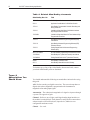
Table A lists several Allen-Bradley documents that may help you as you
use these products.
ii
SLC 500™ Universal Analog Input Modules
Table A. Related Allen-Bradley documents
Allen-Bradley Doc. No.
Title
1747-2.30
SLC 500 System Overview
SGI-1.1
Application Considerations for Solid State Controls
1770-4.1
Allen-Bradley Programmable Controller Grounding and
Wiring Guidelines
1747-6.2
Installation & Operation Manual for Modular Hardware
Style Programmable Controllers
1747-NI001
Installation & Operation Manual for Fixed Hardware Style
Programmable Controllers
1747-6.4
Allen-Bradley Advanced Programming Software (APS)
User Manual
1747-6.11
Allen-Bradley Advanced Programming Software (APS)
Reference Manual
1747-6.3
Getting Started Guide for Advanced Programming
Software (APS)
ABT-1747-TSG001
SLC 500 Software Programmers’s Quick Reference Guide
1747-NP002
Allen-Bradley HHT (Hand-Held Terminal) User Manual
1747-NM009
Getting Started Guide for HHT (Hand-Held Terminal)
SD499
Allen-Bradley Publication Index
AG-7.1
Allen-Bradley Industrial Automation Glossary
To obtain a copy of any of the Allen-Bradley documents listed, contact
your local Allen-Bradley office or distributor.
Terms &
Abbreviations You
Should Know
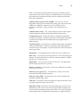
You should understand the following terms and abbreviations before using
this guide.
A/D - Refers to analog-to-digital conversion. The conversion produces a
digital value whose magnitude is proportional to the instantaneous
magnitude of an analog input signal.
Attenuation – The reduction in magnitude of a signal as it passes through
a system. The opposite of gain.
Channel – Refers to one of eight, small-signal analog input interfaces to
the module’s terminal block. Each channel is configured for connection to
a thermocouple or DC millivolt (mV) input device, and has its own
configuration and status words.
Chassis – See rack.
Preface
iii
CJC - (Cold Junction Compensation) The means by which the module
compensates for the offset voltage error introduced by the temperature at
the junction between the thermocouple lead wire and the input terminal
block (the cold junction).
Common mode rejection ratio (CMRR) - The ratio of a device’s
differential voltage gain to common mode voltage gain. Expressed in dB,
CMRR is a comparative measure of a device’s ability to reject
interference caused by a voltage common to its terminal relative to
ground.
Common mode voltage – The voltage difference between the negative
terminal and analog common during normal differential operation.
Configuration word – Contains the channel configuration information
needed by the module to configure and operate each channel. Information
is written to the configuration word through the logic supplied in your
ladder program.
Cut-off frequency - The frequency at which the input signal is attenuated
3 dB by the digital filter. Frequency components of the input signal that
are below the cut-off frequency are passed with under 3 dB of attenuation
for low-pass filters.
dB (decibel) – A logarithmic measure of the ratio of two signal levels.
Data word – A 16-bit integer that represents the value of the analog input
channel. The channel data word is valid only when the channel is enabled
and there are no channel errors.
Digital filter - A low-pass filter of the A/D converter. The digital filter
provides high-frequency noise rejection.
Effective resolution – The number of bits in the channel data word that
do not vary due to noise.
Full-scale error (gain error) – The difference in slope between the
actual and ideal analog transfer functions.
Full-scale range (FSR) – The difference between the maximum and
minimum specified analog values.
Gain drift – The change in full-scale transition voltage measured over the
operating temperature range of the module.
Input data scaling - Depends on the data format that you select for the
channel data work. You can select from scaled-for-PID or Engineering
Units for millivolt, milliamp, thermocouple, RTD, or CJC inputs, which you
must compute to fit your application’s temperature or voltage resolution.
iv
SLC 500™ Universal Analog Input Modules
Local System - A control system with I/O chassis within several feet of
the processor, and using 1746-C7 or 1746-C9 ribbon cable for
communication.
LSB (least significant bit) – The bit that represents the smallest value
within a string of bits. The “weight” of this value is defined as the fullscale range divided by the resolution.
Mulitplexer – A switching system that allows several input signals to
share a common A/D converter.
Normal mode rejection (differential mode rejection) – A logarithmic
measure, in dB, of a device’s ability to reject noise signals between or
among circuit signal conductors, but not between the equipment grounding
conductor or signal reference structure and the signal conductors.
Module update time – See channel update time.
Remote system - A control system shere the chassis can be located
several thousand feet from the processor chassis. Chassis communication
is via the 1747-SN Scanner and 1747-ASB Remote I/O Adapter.
Resolution – The smallest detectable change in a measurement, typically
expressed in engineering units (e.g. 0.15 °C) or as a number of bits. For
example, a 12-bit system has 4096 possible output states. It can therefore
measure 1 part in 4096. See also effective resolution.
RTD (Resistance Temperature Detector) - A temperature sensing
element with 2, 3, 4, lead wires. It uses the basic characteristics that
electrical resistance of metals increases with temperature. When a small
current is applied to the RTD, it creates a voltage that varies with
temperature. This voltage is processed and converted by the RTD module
into a temperature value.
Sampling time - The time required by the A/D converter to sample an
input channel.
Status word – Contains status information about the channel’s current
configuration and operational state. You can use this information in your
ladder program to determine whether the channel data word is valid.
Step response time – The time required for the A/D signal to reach
95% of its expected, final value, given a full-scale step change in the
output data word.
Update time – The time for the module to sample and convert a channel
input signal and make the resulting value available to the SLC processor.
Table of Contents
Preface
Who Should Use This Guide .................................................................................. i
What This Guide Covers ......................................................................................... i
Related Allen-Bradley Documents ......................................................................... i
Table A. Related Allen-Bradley documents .......................................................... ii
Terms & Abbreviations You Should Know ............................................................ ii
Module Overview
Installing And Wiring
Your Module
Things To Consider
Before Using
Your Module
Chapter 1
General Description ................................................................................................ 1
System Overview .................................................................................................... 3
Compatibility with RTD and Resistance devices and cables ............................. 6
Block Diagram ......................................................................................................... 7
Chapter 2
Electrostatic Damage ............................................................................................. 9
Power Requirements .............................................................................................. 9
Shunt Configuration .............................................................................................. 10
JP1, JP2, JP3, JP4, JP5, JP6, JP7, and JP8 Setup ........................................ 11
Current Input ......................................................................................................... 11
Non-Current Input ................................................................................................. 11
JP11 Setup ............................................................................................................ 11
JP9, JP10, and JP12 Setup ................................................................................. 12
Setting For RTD or Resistance Inputs ............................................................... 12
Setting For Non-RTD or Resistance Inputs ....................................................... 12
Selecting A Rack Slot ........................................................................................... 13
Module Installation and Removal ........................................................................ 13
Wiring Your Module ............................................................................................... 15
Wiring RTD or Resistance Sensors to the NI8u Module.................................. 16
Preparing and Wiring the Cables ........................................................................ 18
Chapter 3
Module ID Code .................................................................................................... 23
Module Addressing ............................................................................................... 23
Channel Filter Frequency Selection ................................................................... 25
Update Time .......................................................................................................... 29
Channel Turn-On, Turn-Off, and Reconfiguration Times .................................. 30
Auto-Calibration .................................................................................................... 30
Response to Slot Disabling ................................................................................. 32
vi
SLC 500™ Universal Analog Input Modules
Channel
Configuration, Data,
and Status
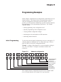
Programming
Examples
Testing Your Module
Maintaining Your
Module
And Ensuring Safety
Appendices
Chapter 4
Channel Configuration ......................................................................................... 35
Channel Configuration Procedure ...................................................................... 36
Channel Data Word Resolution ........................................................................... 42
Channel Data/Status Word .................................................................................. 45
Channel Status Checking .................................................................................... 45
Chapter 5
Initial Programming ............................................................................................... 51
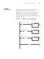
Dynamic Programming ........................................................................................ 53
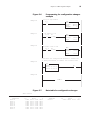
Verifying Channel Configuration Changes ......................................................... 54
Interfacing to the PID Instruction ........................................................................ 56
Monitoring Channel Status Bits .......................................................................... 57
Chapter 6
Module and Channel Diagnostics ....................................................................... 63
LED Indicators ....................................................................................................... 64
Interpreting I/O Error Codes ................................................................................ 66
Verifying With Test Instrumentation..................................................................... 67
Chapter 7
Preventive Maintenance ....................................................................................... 69
Safety Considerations .......................................................................................... 69
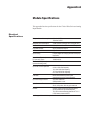
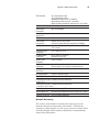
Appendix A : Module Specifications
Electrical Specifications ....................................................................................... 73
Physical Specifications ......................................................................................... 74
EnvironmentalSpecifications ............................................................................... 74
Input Specifications .............................................................................................. 74
Appendix B: Thermocouple Descriptions .......................................................... 91
J Type Thermocouples ......................................................................................... 91
K Type Thermocouples ......................................................................................... 93
T Type Thermocouples ......................................................................................... 95
E Type Thermocouples ......................................................................................... 97
R Type Thermocouples ........................................................................................ 99
S Type Thermocouples ...................................................................................... 100
B Type Thermocouples ...................................................................................... 102
N Type Thermocouples ..................................................................................... 103
References ......................................................................................................... 106
Preface
vii
Appendix C: Using Grounded Junction,
Ungrounded Junction, and Exposed Junction Thermocouples
Thermocouple Types ......................................................................................... 113
Isolation ............................................................................................................... 114
Getting Technical Assistance ............................................................................ 117
Declaration of Conformity ................................................................................. 117
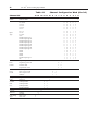
Figures
Figure 2.1
Figure 2.2
Figure 2.3
Figure 2.4
Figure 3.1
Figure 3.2
Figure 3.3
Figure 3.4
Figure 3.5
Figure 5.1
Figure 5.2
Figure 5.3
Figure 5.4
Figure 5.5
Figure 5.6
Figure 5.7
Figure 5.8
Figure 5.9
Figure 5.10
Figure 5.11
Figure 6.1
Module insertion into a rack ........................................................... 14
Terminal block diagram with CJC sensors ................................... 15
Ferrite EMI suppressor for CE compliance .................................. 20
Terminal block diagram with input cable ....................................... 20
Image table ....................................................................................... 24
Signal attenuation with 10 Hz input filter ...................................... 27
Signal attenuation with 50 Hz input filter ...................................... 27
Signal attenuation with 60 Hz input filter ...................................... 28
Signal attenuation with 250 Hz input filter .................................... 28
Channel configuration ..................................................................... 51
Data table for initial programming .................................................. 52
Initial programming example .......................................................... 52
Dynamic programming example .................................................... 53
Data table for dynamic programming ............................................ 54
Programming for configuration changes example ....................... 55
Data table for configuration changes............................................. 55
Programming for PID Control Example ........................................ 56
Data table for PID Control .............................................................. 57
Monitoring channel status bits example ....................................... 58
Data table for monitoring channel status bits ............................... 58
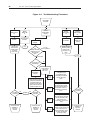
Troubleshooting Flowchart .............................................................. 68
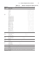
Tables
Table
Table
Table
Table
Table
Table
Table
Thermocouple Temperature Ranges .............................................. 1
RTD Temperature Ranges ................................................................ 2
Millivolt Input Ranges ........................................................................ 2
Current Input Ranges ........................................................................ 2
Resistance Input Range ................................................................... 2
Hardware Features ............................................................................ 3
Recommendations to minimize interference from radiated
electrical noise ................................................................................... 5
Cable Specifications .......................................................................... 6
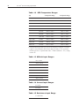
Maximum current drawn by the module ........................................ 10
Cut-off frequency, step response time, and effective resolution
(based on filter frequency) .............................................................. 26
Channel Sampling Time ................................................................. 29
1.1
1.2
1.3
1.4
1.5
1.6
1.7
Table 1.8
Table 2.1
Table 3.1
Table 3.2
viii
SLC 500™ Universal Analog Input Modules
Table 4.1
Table 4.2
Table 4.3
Table 4.4
Table 4.5
Table 6.1
Table 6.2
Channel Configuration Word (O:e.3:0).......................................... 36
Channel Configuration Word (O:e.7:4).......................................... 37
1746sc-NI8u Universal Module Channel Data Word Format ........................................................... 41
1746sc-NI8u Thermocouple Module - ........................................... 42
Channel 0-7 Status Word (I:e.0 through I:e.7) Bit Definitions ................................................................................... 46
Module-status LED .......................................................................... 64
Module-status and Channel-status LED ....................................... 64
Chapter 1
Module Overview
This chapter describes the universal analog input module and explains how
the SLC controller reads thermocouple or millivolt analog input data from
the module. Read this chapter to familiarize yourself further with your
universal analog input module. This chapter covers:
• general description and hardware features
• an overview of system and module operation
• block diagram of channel input circuits
General Description
This module is designed exclusively to mount into Allen-Bradley 1746 I/
O racks for use with Allen-Bradley SLC 500 fixed and modular systems.
The module stores digitally converted thermocouple, RTD, millivolt (mV),
volt (V), milliamp (mA), and CJC temperature analog data in its image
table for retrieval by all fixed and modular SLC 500 processors. The
module supports connections of up to eight channels of thermocouple,
current or voltage inputs, OR four channels of RTD or resistance inputs
and four channels of thermocouple, current or voltage inputs.
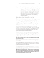
Input Ranges
The following tables provide compatibility information on the supported
thermocouple types and their associated temperature ranges, the
supported RTD types and their associated temperature ranges, as well as
the millivolt, volt, milliamp and resistance input types supported by the
NI8u module. To determine the practical temperature range of your
thermocouple, refer to the specifications in appendices A and B. Detailed
accuracy specifications for all input types can be found in appendix A.
Table 1.1
Thermocouple Temperature Ranges
Type
°C Temperature Range
°F Temperature Range
J
K
T
B
E
R
S
N
C
CJC Sensor
-210°C to 760°C
-270°C to 1370°C
-270°C to 400°C
300°C to 1820°C
-270°C to 1000°C
0°C to 1768°C
0°C to 1768°C
0°C to 1300°C
0°C to 2315°C
-25°C to 105°C
-346°F to 1400°F
-454°F to 2498°F
-454°F to 752°F
572°F to 3308°F
-454°F to 1832°F
32°F to 3214°F
32°F to 3214°F
32°F to 2372°F
32°F to 4199°F
-13°F to 221°F
2
SLC 500™ Universal Analog Input Module
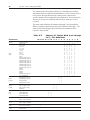
Table 1.2 RTD Temperature Ranges
Type
°C Temperature Range
Platinum (385)1
°F Temperature Range
100 Ohm
-200°C to +850°C
-328°F to +1562°F
200 Ohm
-200°C to +750°C
-328°F to +1382°F
500 Ohm
-200°C to +850°C
-328°F to +1562°F
1000 Ohm
-200°C to +850°C
-328°F to +1562°F
100 Ohm
-200°C to +630°C
-328°F to +1166°F
200 Ohm
-200°C to +630°C
-328°F to +1166°F
500 Ohm
-200°C to +630°C
-328°F to +1166°F
1000 Ohm
-200°C to +630°C
-328°F to +1166°F
Copper (426)
10 Ohm
-100°C to +260°C
-148°F to +500°F
Nickel (618)
120 Ohm
-100°C to + 260°C
-148°F to +500°F
Nickel (672)
120 Ohm
-80°C to +260°C
-112°F to + 500°F
Platinum (3916)1
1=The digits following the RTD type represent the temperature coefficient of resistance
(alpha, a), which is defined as the resistance change per Ohm per °°C. For instance,
Platinum 385 refers to a platinum RTD with a = 0.00385 Ohms/Ohm - °°C, or simply
0.00385/°°C.
Table 1.3 Millivolt Input Ranges
-50 to +50 mV
-100 to +100 mV
-500 to +500 mV
-2.0 to +2.0 V
0 to +5.0 V
1.0 to +5.0 V
0 to 10.0 V
-10.0 to +10.0 V
Table 1.4 Current Input Ranges
4 to 20 mA
0 to 20 mA
Table 1.5 Resistance Input Range
0 to 3000 Ohms
Chapter 1: Module Overview
3
All eight input channels are individually configurable for thermocouple,
millivolt, volt, or milliamp input types. Channels 4 through 7 can be defined
for RTD or resistance inputs, and then can be individually configured for a
specific RTD or resistance type. Each input channel provides broken
input, over-range, and under-range detection and indication, when enabled.
Hardware Features
The module fits into any single slot for I/O modules in either an SLC 500
modular system or an SLC 500 fixed system expansion chassis (1746-A2).
It is a Class 11 module (uses 8 input words and 8 output words).
1
Requires use of Block Transfer in a remote configuration.
The module utilizes two removable terminal blocks, that provides
connections for the eight input channels. There are two cold-junction
compensation (CJC) sensors that compensate for the cold junction at
ambient temperature rather than at freezing (0°C). There are four current
sources for supplying the RTD or resistance sensors. The module is
configured through software, with jumpers used to define RTD,
resistance, current or voltage input paths.
Table 1.6 Hardware Features
Hardware
Function
Channel Status LED Indicators
Display operating and fault status of channels 0-7
Module Status LED
Displays operating and fault status of the module
Side Label (Nameplate)
Provides module information
Removable Terminal Block
Provides electrical connection to input devices
Door Label
Permits easy terminal identification
Self Locking Tabs
Secure module in chassis slot
Diagnostic LEDs
The module contains diagnostic LEDs that help you identify the source of
problems that may occur during power-up or during normal operation.
Power-up and channel diagnostics are explained in Chapter 6, Testing
Your Module.
System Overview
The module communicates with the SLC 500 processor and receives
+5 Vdc and +24 Vdc power from the system power supply through
the parallel backplane interface. No external power supply is
required. You may install as many universal modules in the system
as the power supply can support.
4
SLC 500™ Universal Analog Input Module
The first four input channels (0 through 3) can receive input signals from
thermocouples, millivolt, volt, or milliamp devices. The last four input
channels (4 through 7) can receive input signals from thermocouples,
millivolt, volt, milliamp, or 2, 3 or 4-wire RTD or resistance devices. If
RTD or resistance inputs are selected, channels 4 through 7 can be
individually configured for the supported RTD or resistance types.
When configured for thermocouple input types, the module converts
analog input voltages into cold-junction compensated and linearized, digital
temperature readings. The module uses the National Institute of
Standards and Technology (NIST) linearization tables based on ITS-90 for
thermocouple linearization.
When configured for RTD input types, the module converts the analog
input voltages into digital temperature readings, based on the alpha type,
wire type, and ohms specified. The standards used are the JIS C 16041997 for the Pt 385 RTD types, the JIS C 1604-1989 for the Pt 3916 RTD
types, SAMA RC21-4-1966 for the 10Ω Cu 426 RTD, DIN 43760 Sept.
1987 for the 120Ω Ni 618 RTD, and MINCO Application Aid #18 May
1990 for the 120Ω Ni 672 RTD.
When configured for millivolt, volt, milliamp, or resistance analog inputs,
the module converts the analog values directly into digital counts. For
those input types, the module assumes that the input signal is linear prior to
input into the module.
System Operation
At power-up, the module checks its internal circuits, memory, and basic
functions. During this time the module status LED remains off. If the
module finds no faults, it turns on its module status LED.
After completing power-up checks, the module waits for valid channel
configuration data from your SLC ladder logic program (channel status
LEDs are off). After channel configuration data is transferred and
channel enable bits are set for one or more channels, the module turns on
its channel status LEDs. Then it continuously converts the inputs to the
data format you selected for the channel.
Each time the module reads an input channel, the module tests that data
for a fault, i.e. over-range, or under-range condition. If open-circuit
detection is enabled, the module tests for an open circuit condition. If it
detects an open-circuit, over-range, or under-range condition, the module
sets a unique bit in the channel status word and causes the channel status
LED to blink.
The SLC processor reads the converted thermocouple, RTD,
resistance, millivolt, volt, or milliamp data from the module at the
end of the program scan, or when commanded by the ladder
program. After the processor and module determine that the data
transfer was made without error, the data can be used in your ladder
program.
Chapter 1: Module Overview
5
Module Operation
The module’s input circuitry consists of eight differential analog inputs,
multiplexed into an A/D converter. The A/D converter reads the analog
input signals and converts them to digital counts. The input circuitry also
continuously samples the CJC sensors and compensates for temperature
changes at the cold junction (terminal block). The module can be used
with remote CJC sensor inputs. The sensors must be Analog Devices
AD592CN temperature transducers. The module will not accept other
CJC sensor inputs, and thermocouple inputs will not function properly if
incorrect CJC sensors are used.
Module Addressing
The module requires eight words each in the SLC processor’s input and
output image tables. Addresses for the module in slot e are as follows:
I:e.0-7
thermocouple/mV/V/mA, RTD, resistance or status
data for channels 0-7, respectively
O:e.0-7 configuration data for channels 0-7, respectively.
Compatibility with Thermocouple, Current, and
Millivolt Devices & Cables
The module is compatible with the following standard types of
thermocouples: B, E, J, K, N, R, S, T and C and extension wire.
Refer to appendices B and C for details. The module is also
compatible with a variety of voltage and current devices with an
output of ±50, ±100 mV, +500mV, ±2V, 0-5V, 1-5V, 0-10V, ±10V,
0-20mA, and 4-20mA.
To minimize interference from radiated electrical noise, we
recommend twisted-pair and highly shielded cables such as the
following:
Table 1.7 Recommendations to minimize
interference from radiated electrical noise
For This Type of Device
We Recommend This Cable (or equivalent)
Thermocouple Type J
EIL Corp. J20-5-502
Thermocouple Type K
EIL Corp. K20-5-510
Thermocouple Type T
EIL Corp. T20-5-502
Other Thermocouple Types
consult with EIL Corp or other manufacturers
mV, V, mA devices
Belden 8761, shielded, twisted-pair
6
SLC 500™ Universal Analog Input Module
Compatibility with RTD and Resistance devices and
cables
The module is compatible 100Ω Platinum 385, 200Ω Platinum 385, 55Ω
Platinum 385, 1000Ω Platinum 385, 100Ω Platinum 3916, 200Ω Platinum
3916, 500Ω Platinum 3916, 1000Ω Platinum 3916, 10Ω Copper 426, 120Ω
Nickel 618 and 120Ω Nickel 672 RTD types and 3000Ω resistance inputs,
and 3 possible wire types (2 wire, 3 wire, or 4 wire). Each RTD input
individually supports four input pins on the terminal block: one excitation
current source (EXC+), one excitation current drain (EXC-), one sense
positive (CH+) and one sense negative (CH-). Only those pins are
connected that are required by the selected RTD or resistance wire type.
For 2, 3, or 4 wire configurations, the module can support a maximum
combined cable length associated with an overall cable impedance of 25
ohms or less without exceeding its input limitations. The accuracy
specifications provided herein do not include errors associated with
unbalanced cable impedance.
Since the operating principle of the RTD and resistance inputs is based on
the measurement of resistance, take special care in selecting your input
cable. For 2-wire or 3-wire configuration, select a cable that has a
consistent impedance throughout its entire length. For 2-wire
configurations, we recommend that you use Belden #9501 (or
equivalent). For 3-wire configurations, we recommend that you use
Belden #9533 (or equivalent) for short installation runs (less than 100
feet) or use Belden #83503 (or equivalent) for longer runs (greater
than 100 feet) and in high humidity environments.
Table 1.8 Cable Specifications
Description
Belden #9501
Belden#9533
Belden#83503
When used?
For 2-wire RTDs and
potentiometers.
For 3-wire RTDs and
potentiometers. Short
runs less than 100 feet
and normal humidity
levels.
For 3-wire RTDs and
potentiometers. Long
runs greater than 100
feet or high humidity
levels.
Conductors
2, #24 AWG tinned
copper (7x32)
3, #24 AWG tinned
copper (7x32)
3, #24 AWG tinned
copper (7x32)
Shield
Beldfoil aluminum
polyester shield
w/ copper drain wire.
Beldfoil aluminum
polyester shield
w/copper drain wire.
Beldfoil aluminum
polyester shield
w/copper drain wire.
Insulation
PVC
S-R PVC
Teflon
Jacket
Chrome PVC
Chrome PVC
Red teflon
Agency
Approval
NEC Type CM
NEC Type CM
NEC Art-800, Type CMP
Temperature
Rating
80°C
80°C
200°C
Chapter 1: Module Overview
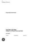
Block Diagram
7
Vcc
Multiplexers
DC Voltage +
Analog Input -
Thermocouple
Input
CJCA +
Sensor CH2 +
CH2 SHIELD 2/3
CH 3 +
CH 3 EXC 6 +
CH6 +
CH6 EXC 6 Shield 6/7
EXC 7 +
CH 7 +
CH 7 EXC 7 -
Analog
to Digital
Converter
Vcc
User Selected
Filter Frequency
Vcc
0-20 mA +
Current Input -
RTD or
resistance
Input
CH 0 +
CH 0 SHIELD 0/1
CH 1+
CH
1RTD
Sense + EXC 4 +
CH 4 +
CH 4 Sense
EXC 4 Return
SHIELD 4/5
EXC 5 +
CH 5 +
CH 5 EXC 5 CJCB +
Sensor -
Digital
Filter
Vcc
Digital
Value
8
SLC 500™ Universal Analog Input Module
Chapter 2
Installing And Wiring Your Module
Read this chapter to install and wire your module. This chapter
covers:
• avoiding electrostatic damage
• determining power requirements
• installing the module
• wiring signal cables to the module’s terminal block
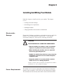
Electrostatic
Damage
Electrostatic discharge can damage semiconductor devices inside this
module if you touch backplane connector pins. Guard against
electrostatic damage by observing the following precautions:
!
CAUTION
ELECTROSTATICALLY SENSITIVE COMPONENTS
• Before handling the module, touch a grounded
object to rid yourself of electrostatic charge.
• When handling the module, wear an approved
wrist strap grounding device.
• Handle the module from the front, away from the
backplane connector. Do not touch backplane
connector pins.
• Keep the module in its static-shield container
when not in use or during shipment.
Failure to observe these precautions can degrade the module’s
performance or cause permanent damage.
Power Requirements
The module receives its power through the SLC-500 chassis backplane
from the fixed or modular +5 VDC and +24 VDC chassis power supply.
The maximum current drawn by the module is shown in the table below.
10
SLC 500™ Universal Analog Input Module
Table 2.1.
module
Maximum current drawn by the
5VDC Amps
0.120
24VDC Amps
0.100
When using the module in a modular system, add the values shown
above to the requirements of all other modules in the SLC to prevent
overloading the chassis power supply.
When using the module in a fixed controller, be sure not to exceed
the power supply rating for the 2-slot I/O chassis.
Considerations for a Modular System
Place your module in any slot of an SLC-500 modular, or modular
expansion chassis, except for the left-most slot (slot 0) reserved for
the SLC processor or adapter modules.
Considerations for a Fixed Controller
The power supply in the 2-slot SLC 500 fixed I/O chassis (1746-A2)
can support only specific combinations of modules. Make sure the
chassis power supply can support the NI8u and additional module
power requirements.
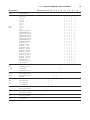
Shunt
Configuration
The 1746sc-NI8u module is a multi-purpose, multi-functional
module, that is capable of supporting many different input types in a
very small package. There are a few shunts on the board that allow
the user to define input paths properly, which are imperative for the
configuration control to allow proper utilization of the module. JP1
through JP8 supports the current input mode options of each of the
inputs channels, 0 through 7, respectively. In order to define
channels 4 through 7, JP9 and JP10, must be configured properly.
JP11 is used at the factory and should not be modified. JP12
indicates whether or not RTD or resistance inputs are to be used in
the configuration. The module is shipped with all current input
shunts in place, and the remaining shunts installed for non-RTD or
resistance inputs. The shunts are to be modified prior to installation
of the module. Proper precautions for electrostatic handling should
be followed. Small needlenose pliers may be used to configure the
shunts, if needed.
!
ATTENTION:
Never touch the module without
being properly strapped and connected to ground.
Electrostatic damage may result.
11
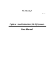
Chapter 2: Installing And Wiring Your Module
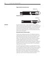
The following diagram shows the module outline defining the placement of
the various shunts, looking at the primary side of the board, with the
terminal block pointing up. A brief description of each follows.
Terminal Block Header
JP1
JP2
JP3
JP4
JP5
JP6
JP7
JP8
JP9
JP10
JP11
JP12
JP1, JP2, JP3, JP4,
JP5, JP6, JP7, and
JP8 Setup
There are eight shunts corresponding to eight inputs, respectively,
that exist to support the 0 to 20mA or 4 to 20mA current input
selections. JP1 corresponds to channel 0, and JP8 corresponds to
channel 7. The shunts of JP2 through JP7 follow for channels 1
through 6, respectively. These shunts are two pin headers that only
need to be connected if a channel is to be configured for current
input. If the channel is to be used for any other type (thermocouple,
millivolt, voltage for channels 0 through 3, or thermocouple,
millivolt, voltage, RTD, or resistance for channels 4 through 7), then
the pins are to be left open and unconnected.
Current Input
Shunt in place
Non-Current Input
Shunt removed
JP11 Setup
Located in the bottom right hand corner, JP11 should always have
pins 1 and 2 connected as shown. This shunt is used during
manufacturing of the module, and should never be moved by the
user.
JP11
12
SLC 500™ Universal Analog Input Module
JP9, JP10, and JP12
Setup
Setting For RTD or
Resistance Inputs
The NI8u module supports up to four RTD or resistance inputs on
channels 4 through 7. In order to properly support RTD or resistance
inputs, JP9, JP10, and JP12 have to be configured correctly. The
function of JP9 and JP10 is to define the input path for the channels 4
through 7. JP9 and JP10 are four pin headers toward the right side of
the board, looking at the primary side of the board with the terminal
block pointing up. JP12 is a three pin header on the very bottom
right hand corner, below JP11.
The module will either support zero RTD or resistance inputs or four
RTD or resistance inputs in channels 4 through 7. To properly
configure JP9 and JP10 for RTD or resistance, set the shunts across
pins 2 and 3 of the four pin headers. JP12 also needs to have pins 2
and 3 connected when RTD or resistance are to be used, as shown
below.
JP9
JP10
JP12
Setting For Non-RTD
or Resistance Inputs
If RTD and resistance inputs are not used, and channels 4 through 7
are to be defined as thermocouple inputs, current inputs, millivolt or
voltage inputs, jumper pins 1 and 2 together, jumper pins 3 and 4
together, of JP9 and JP10, as defined below. JP12 also needs to have
pins 1 and 2 connected when RTD and resistance inputs are not in
use.
JP9
JP10
JP12
Chapter 2: Installing And Wiring Your Module
Selecting A Rack
Slot
13
Two factors determine where you should install your module in the
rack: ambient temperature and electrical noise. When selecting a slot
for your module, try to position your module:
• in a rack close to the bottom of the enclosure (where the air is
cooler)
• away from modules that generate significant heat, such as 32-point
input/output modules
• in a slot away from ac or high-voltage dc modules, hard contact
switches, relays, and ac motor drives
• away from the rack power supply (if using a modular system)
Remember that in a modular system, the processor always occupies
the first slot of the rack.
!
1746scRACK_______SLOT_______
NI8u
TB1
When installing the module in a chassis, it is not necessary to remove
the terminal blocks from the module. However, if the terminal blocks
are removed, use the write-on label located on the side of the terminal
blocks to identify the module location and type.
1746scRACK_______SLOT_______
NI8u
TB2
Module Installation
and Removal
CAUTION
POSSIBLE EQUIPMENT OPERATION
Before installing or removing your module, always
disconnect power from the SLC 500 system and from
any other source to the module (in other words, don’t
“hot swap” your module), and disconnect any devices
wired to the module.
Failure to observe this precaution can cause unintended
equipment operation and damage.
14
SLC 500™ Universal Analog Input Module
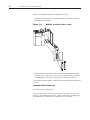
To insert your module into the rack, follow these steps:
1. Align the circuit board of your module with the card guides at the top
and bottom of the chassis.
Figure 2.1.
Module insertion into a rack
TB1
TB2
2. Slide your module into the chassis until both top and bottom retaining
clips are secure. Apply firm even pressure on your module to attach it
to its backplane connector. Never force your module into the slot.
Cover all unused slots with the Card Slot Filler, Allen-Bradley part number
1746-N2.
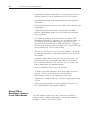
Terminal Block Removal
To remove the terminal block:
Using a screwdriver or needle-nose pliers, carefully unscrew and
then pry the terminal block loose. When removing or installing the
terminal block be careful not to damage the CJC sensors.
15
Chapter 2: Installing And Wiring Your Module
Figure 2.2.
Terminal block diagram with CJC
sensors
CJC Sensors
CJCA+
CH0Shield 0/1
CJCACH2+
CH1+
CH2-
CH1-
SHIELD 2/3
EXC4+
CH3+
CH4+
CH3-
CH4EXC4-
EXC6+
CH6+
Shield 4/5
EXC5+
CH5+
CH6EXC6SHIELD 6/7
CH5-
EXC7+
EXC5-
CH7+
CJCB+
CJCB-
CH7EXC7-
CJC Sensors
!
TB1
LEDS
CH0+
TB2
CAUTION
POSSIBLE EQUIPMENT OPERATION
Before wiring your module, always disconnect power
from the SLC 500 system and from any other source to
the module.
Failure to observe this precaution can cause unintended
equipment operation and damage.
Wiring Your Module
Follow these guidelines to wire your input signal cables:
• Power, input, and output (I/O) wiring must be in accordance with
Class 1, Division 2 wiring methods [Article 501-4(b) of the
National Electrical Code, NFPA 70] and in accordance with the
authority having jurisdiction.
• Peripheral equipment must be suitable for the location in which it
is used.
• Route the field wiring away from any other wiring and as far as
possible from sources of electrical noise, such as motors,
16
SLC 500™ Universal Analog Input Module
transformers, contactors, and ac devices. As a general rule, allow at
least 6 in. (about 15.2 cm) of separation for every 120 V of power.
• Routing the field wiring in a grounded conduit can reduce electrical
noise further.
• If the field wiring must cross ac or power cables, ensure that they cross
at right angles.
• To limit the pickup of electrical noise, keep thermocouple, RTD,
millivolt, and milliamp signal wires as far from power and load
lines as possible.
• For improved immunity to electrical noise, use Belden 8761
(shielded, twisted pair) or equivalent wire for millivolt sensors; or
use shielded, twisted pair thermocouple extension lead wire
specified by the thermocouple or RTD manufacturer. Using the
incorrect type of thermocouple extension wire or not following the
correct polarity may cause invalid readings.
• There is one shield pin for every two input channels. All shields
are internally connected, so any shield terminal can be used with
any channel.
• Ground the shield drain wire at only one end of the cable. The
preferred location is at the shield connections on the terminal
block. (Refer to IEEE Std. 518, Section 6.4.2.7 or contact your
sensor manufacturer for additional details.)
• Keep all unshielded wires as short as possible.
• To limit overall cable impedance, keep input cables as short as
possible. Locate your I/O chassis as near the RTD or
thermocouple sensors as your application will permit.
• Tighten screw terminals with care. Excessive tightening can strip
a screw.
• Follow system grounding and wiring guidelines found in your
SLC 500 Installation and Operation Manual.
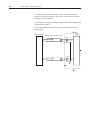
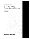
Wiring RTD or
Resistance Sensors
to the NI8u Module
The NI8u module supports two, three, and four wire RTDs or
resistance inputs connected individually to the module (channels 4
through 7), as shown in the figure below.
17
Chapter 2: Installing And Wiring Your Module
2-Wire RTD Interconnection
EXC4+
ADD
JUMPER
RTD
RETURN
CH4+
CH4EXC4Shield 4/5
CABLE SHIELD
3-Wire RTD Interconnection
ADD
JUMPER
EXC4+
RTD
CH4+
SENSE
CH4EXC4Shield 4/5
RETURN
CABLE SHIELD
4-Wire RTD Interconnection
RTD
SENSE POS
EXC4+
CH4+
SENSE NEG
CH4-
RETURN
EXC4Shield 4/5
CABLE SHIELD
These are:
* 2-wire RTDs, which are composed of 2 RTD lead wires (RTD and
Return)
* 3-wire RTDs, which are composed of a Sense and 2 RTD lead wires
(RTD and Return)
* 4-wire RTDs, which are composed of 2 Sense and 2 RTD lead wires
(RTD and Return).
In any RTD sensing system, it is important that the lead and sense wire
resistances are matched as much as possible. The lead lengths, and their
resulting impedances, must be matched and kept small to eliminate the
introduction of connectivity errors. The 4-wire RTDs are the most
accurate, with 2-wire RTDs being the most inaccurate. In 2-wire the lead
resistance adds error to the resulting degree reading. With a 200µA
current source, 1Ω of lead resistance adds 200µV, or 3.45°C error, with
the 100Ω 385 alpha type. To gain an understanding of how lead
resistance affects RTD readings, the µV/C for each RTD type is listed
below. The current source is 200µA.
18
SLC 500™ Universal Analog Input Module
V/°C
RTD Type
100Ω Pt 385
200Ω Pt 385
500Ω Pt 385
1000Ω Pt 385
58µV/°C
116µV/°C
290µV/°C
580µV/°C
100Ω Pt 3916
200Ω Pt 3916
500Ω Pt 3916
1000Ω Pt 3916
68µV/°C
136µV/°C
340µV/°C
680µV/°C
10Ω Cu 426
4.3µV/°C
120Ω Ni 618
120Ω Ni 672
110µV/°C
130µV/°C
The accuracies specified for the NI8u RTDs do not include errors due to
lead resistance imbalances.
Important: To ensure temperature or resistance value accuracy, the
resistance difference of the cable lead wires must be equal to or less
than 0.01 ohms.
There are several ways to insure that the lead values match as closely as
possible. They are as follows:
* Keep total lead resistance as small as possible, and less than 25 ohms.
* Use quality cable that has a small tolerance impedance rating.
* Use a heavy gauge lead wire which has less resistance per foot.
Preparing and
Wiring the Cables
To prepare and connect cable leads and drain wires, follow these
steps:
Signal Wires
Cable
Drain Wire
(Remove foil shield and drain wire
from sensor-end of cable.)
Signal Wires
(At the module-end of the cable, extract
the drain wire but remove the foil shield.)
1. At each end of the cable, strip some casing to expose individual
wires.
2. Trim signal wires to 5-inch lengths beyond the cable casing. Strip
about 3/16 inch (4.76 mm) of insulation to expose the ends of the
wires.
3. At the module-end of the cables (see figure above):
Chapter 2: Installing And Wiring Your Module
19
- extract the drain wire and signal wires
- remove the foil shield
- bundle the input cables with a cable strap
4. Connect pairs of drain wires together, Channels 0 and 1, Channels 2
and 3, Channels 4 and 5, Channels 6 and 7. Keep drain wires as short
as possible.
5. Connect the drain wires to the shield inputs of the terminal block.
Channel 0 and 1 drain wires to the shield 0/1 input pin
Channel 2 and 3 drain wires to the shield 2/3 input pin
Channel 4 and 5 drain wires to the shield 4/5 input pin
Channel 6 and 7 drain wires to the shield 6/7 input pin
6. Connect the signal wires of each channel to the terminal block.
Important: Only after verifying that your connections are correct
for each channel, trim the lengths to keep them short. Avoid
cutting leads too short.
7. Connect the chassis ground terminal/lug to the nearest chassis
mounting bolt with 14 gauge wire. (Looking at the face of the
module, the terminal/lug is near the terminal block and above
power supply PS2 on the primary side of the PCB.)
8. At the source-end of cables from mV devices:
- remove the drain wire and foil shield
- apply shrink wrap as an option
- connect to mV devices keeping the leads short
Important: If noise persists, try grounding the opposite end of the
cable, instead (Ground one end only.)
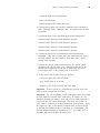
Important: For CE compliance, Ferrite EMI Suppressors are needed
on each channel’s terminal block connection. If remote CJCs are
installed, shielded wire must be used and a Ferrite EMI suppressor is
needed on each CJC input connection. The drain wire of the CJC
cable must be connected to a shield connection at the module. Apply
the suppressor close to the module terminal block, as shown below.
A Steward Part 28B2024-0A0 or equivalent is recommended. The
Steward 28B2024-0A0 has an impedance of 157Ω at 25 MHz, 256Ω at
100 MHz, and can accomodate one turn of wire.
20
SLC 500™ Universal Analog Input Module
Figure 2.3
Ferrite EMI suppressor for CE
compliance
Module
Note: Please refer to Appendix C for additional information on
wiring and using grounded junction, ungrounded junction and
exposed juction thermocouple types.
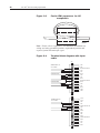
Figure 2.4
Terminal block diagram with input
cable
TB1
CH0+
THERMOCOUPLE, mA,
CH0-
mV or V CABLE
Shield for CH0 and CH1
CH1+
CH1-
4-WIRE RTD CABLE
EXC4+
CH4+
CH4EXC4Shield for CH4 and CH5
3-WIRE RTD CABLE
EXC5+
CH5+
CH5EXC5CJCB+
CJCB-
TB2
THERMOCOUPLE, mA,
mV or V CABLE
CJC A+
CJC A CH2+
CH2Shield for CH2 and CH3
CH3+
CH3EXC6+
CH6+
CH6EXC6Shield for CH6 and CH7
EXC7+
CH7+
CH7EXC7-
Chapter 2: Installing And Wiring Your Module
21
The module also has a ground terminal TB1 which should be grounded to
a chassis mounting bolt with 14 gauge wire.
Cold Junction Compensation (CJC)
!
CAUTION
POSSIBLE EQUIPMENT OPERATION
Do not remove or loosen the cold junction
compensating temperature transducers located on the
terminal block unless you are connecting remote CJCs
to the module. Both CJCs are critical to ensure
accurate thermocouple input readings at each channel.
The module will not operate in thermocouple mode if a
CJC is not connected.
Failure to observe this precaution can cause unintended
equipment operation and damage.
To obtain accurate readings from each of the channels, the cold
junction temperature (temperature at the module’s terminal junction
between the thermocouple wire and the input channel) must be
compensated for. Two cold junction compensating sensors have
been integrated in the removable terminal block. They must remain
installed to retain accuracy. If remote CJC compensation is desired,
the sensors at the terminal block must be removed and the external
sensors wired to the CJCA and CJCB terminals. The remote CJC
sensors must be Analog Devices AD592CN T0-92 style temperature
transducer devices. The module will not function with any other
CJC sensor connected.
22
SLC 500™ Universal Analog Input Module
Chapter 3
Things To Consider Before Using
Your Module
This chapter explains how the module and the SLC processor
communicate through the processor’s I/O image tables. It also
describes the module’s input filter characteristics. Topics discussed
include:
• module ID code
• module addressing
• channel filter frequency selection
• Channel turn-on, turn-off, and reconfiguration times
• response to slot disabling
Module ID Code
The module ID code is a unique number assigned to each type of
1746 I/O module. The ID defines for the processor the type of I/O
module and the number of words used in the processor’s I/O image
table.
With APS software, use the system I/O configuration display to
manually enter the module ID when assigning the slot number during
the configuration. Do this by selecting (other) from the list of
modules on the system I/O configuration display and enter 3500, the
ID code for the 1746sc-NI8u.
No special I/O configuration (SPIO CONFIG) is required. The
module ID automatically assigns the correct number of input and
output words.
If you are using different programming software package, refer to the
documentation that came with your software.
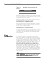
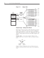
Module Addressing
The following memory map shows you how the SLC processor’s
output and input tables are defined for the module.
24
SLC 500™ Universal Analog Input Module
Figure 3.1
Image table
Bit 15
SLC 5/0X
Data Files
Slot e
Output
Scan
Output Image
8 Words
Output Image
Slot e
Input Image
Thermocouple
Module
Image Table
Channel 0 Configuration Word
Bit 0
Address
Word 0 O:e.0
Channel 1 Configuration Word
Word 1
O:e.1
Channel 2 Configuration Word
Word 2
O:e.2
Channel 3 Configuration Word
Channel 4 Configuration Word
Word 3
O:e.3
Word 4
O:e.4
Channel 5 Configuration Word
Channel 6 Configuration Word
Word 5
O:e.5
Word 6
O:e.6
Channel 7 Configuration Word
Word 7
O:e.7
Channel 0 Data or Status Word
Word 0
I:e.0
Channel 1 Data or Status Word
Word 1
I:e.1
Channel 2 Data or Status Word
Word 2
I:e.2
Channel 3 Data or Status Word
Channel 4 Data or Status Word
Word 3
I:e.3
Word 4
I:e.4
Channel 5 Data or Status Word
Channel 6 Data or Status Word
Word 5
I:e.5
Word 6
I:e.6
Channel 7 Data or Status Word
Word 7
Input
Scan
Input Image
8 Words
Bit 15
Bit 0
I:e.7
Address
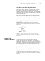
Output Image - Configuration Words
Eight words of the SLC processor’s output image table are reserved
for the module. Output image words 0-7 are used to configure the
module’s input channels 0-7. Each output image word configures a
single channel, and can be referred to as a configuration word. Each
word has a unique address based on the slot number assigned to the
module.
Example Address - If you want to configure channel 2 on the
module located in slot 4 in the SLC chassis, your address would be
O:4.2.
File type
Slot
Word
O:4.2
Element
Delimiter
Word
Delimiter
Chapter 4, Channel Configuration, Data, and Status, gives you
detailed bit information about the data content of the configuration
word.
Chapter 3: Things To Consider Before Using Your Module
25
Input Image - Data Words and Status Words
Eight words of the SLC processor’s input image table are reserved
for the module. Input image words are multiplexed since each
channel has one data word and one status word. The corresponding
configuration word selects whether the channel status or channel data
is in the input image word.
Status bits for a particular channel reflect the configuration settings
that you entered into the configuration (output image) word for that
channel. To receive valid status, the channel must be enabled and the
module must have stored a valid configuration word for that channel.
Each input image word has a unique address based on the slot
number assigned to the module.
Example Address - To obtain the status/data word of channel 2
(input word 2) of the module located in slot 4 in the SLC chassis use
address I:4:2.
File type
Slot
Word
I:4.2
Element
Delimiter
Word
Delimiter
Chapter 4, Channel Configuration, Data, and Status, gives you
detailed bit information about the content of the data word and the
status word.
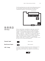
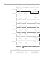
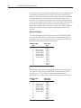
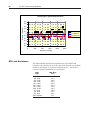
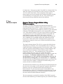
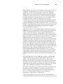
Channel Filter
Frequency Selection
The universal module uses a digital filter that provides high
frequency noise rejection for the input signals. The digital filter is
programmable, allowing you to select from four filter frequencies for
each channel. The digital filter provides the highest noise rejection at
the selected filter frequency. The graphs to follow show the input
channel frequency response for each filter frequency selection.
Selecting a low value (i.e. 10 Hz) for the channel filter frequency
provides the best noise rejection for a channel, but it also increases
the channel update time. Selecting a high value for the channel filter
frequency provides lower noise rejection, but decreases the channel
update time.
The following table shows the available filter frequencies, cut-off
frequency, step response, and ADC effective resolution for each filter
frequency.
26
SLC 500™ Universal Analog Input Module
Table 3.1 Cut-off frequency, step response time, and
effective resolution (based on filter
frequency)
Filter
Frequency
Cut-Off
Frequency
Step
Response
ADC Effective
Resolution
10 Hz
50 Hz
60 Hz
250 Hz
2.62 Hz
13.1 Hz
15.72 Hz
65.5 Hz
300 ms
60 ms
50 ms
12 ms
20.5
19.0
19.0
15.5
The step response is calculated by a 3 x (1/filter frequency) settling time.
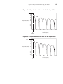
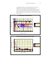
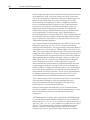
Channel Cut-Off Frequency
The channel filter frequency selection determines a channel’s cut-off
frequency, also called the -3 dB frequency. The cut-off frequency is
defined as the point on the input channel frequency response curve
where frequency components of the input signal are passed with 3
dB of attenuation. All frequency components at or below the cut-off
frequency are passed by the digital filter with less than 3 dB of
attenuation. All frequency components above the cut-off frequency
are increasingly attenuated, as shown in the graphs below.
The cut-off frequency for each input channel is defined by its filter
frequency selection. The table above shows the input channel cut-off
frequency for each filter frequency. Choose a filter frequency so that
your fastest changing signal is below that of the filter’s cut-off
frequency. The cut-off frequency should not be confused with
update time. The cut-off frequency relates how the digital filter
attenuates frequency components of the input signal. The update
time defines the rate at which an input channel is scanned and its
channel data word updated.
27
Chapter 3: Things To Consider Before Using Your Module
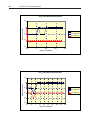
Figure 3.2 Signal attenuation with 10 Hz input filter
-3 dB
0
-20
-40
-60
-80
Amplitude (in dB)
-100
-120
-140
-160
-180
-200
0
10
20
30
40
50
60 Hz
Signal Frequency
2.62 Hz
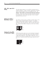
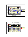
Figure 3.3 Signal attenuation with 50 Hz input filter
-3 dB
0
-20
-40
-60
-80
Amplitude (in dB)
-100
-120
-140
-160
-180
-200
0
13.1 Hz
50
100
150
200
Signal Frequency
250
300 Hz
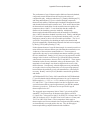
28
SLC 500™ Universal Analog Input Module
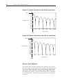
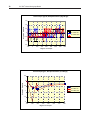
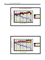
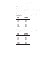
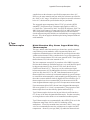
Figure 3.4 Signal attenuation with 60 Hz input filter
-3 dB
0
-20
-40
-60
-80
Amplitude (in dB)
-100
-120
-140
-160
-180
-200
0
60
120
180
240
300
360 Hz
Signal Frequency
15.7 Hz
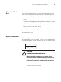
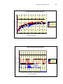
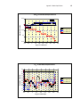
Figure 3.5 Signal attenuation with 250 Hz input filter
-3 dB
0
-20
-40
-60
-80
Amplitude (in dB)
-100
-120
-140
-160
-180
-200
0
250
65.5 Hz
500
750
1000
1250
1500 Hz
Signal Frequency
Channel Step Response
The channel filter frequency determines the channel’s step response.
The step response is time required for the analog input signal to reach
95% of its expected, final value given a full-scale step change in the
input signal. This means that if an input signal changes faster than
the channel step response, a portion of that signal will be attenuated
by the channel filter. Table 6 shows the step response for each filter
frequency.
29
Chapter 3: Things To Consider Before Using Your Module
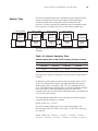
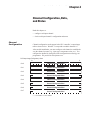
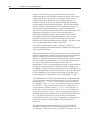
Update Time
The universal module update time is defined as the time required for the
module to sample and convert the input signals of all enabled input
channels and make the resulting data values available to the SLC
processor. It can be calculated by adding the sum of all enabled sample
times, plus one CJC update time or one lead resistance update time.
Channel 0 Disabled
Enabled
Sample
Channel 0
Update CJC
Channel 1 Disabled
Enabled
Sample
Channel 1
Channel 7 Disabled
Channel 2 Disabled
Enabled
Calculate
Previous
Sample
Channel 2
Enabled
Calculate
Previous
Sample
Channel 7
Sample CJC or
Lead Resistance
Calculate
Previous
Calculate
Previous
The following table shows the channel sampling time for each filter
frequency.
Table 3.2 Channel Sampling Time
Channel Sampling Time for Each Filter Frequency (all values ±1 msec)
Channel Sampling Time
250 Hz Filter
60 Hz Filter
50 Hz Filter
10 Hz Filter
26 msec
64 msec
74 msec
314 msec
The times above include a settling time necessary between input channel
readings.
In addition, on each module scan the module will sample either one CJC
input or one lead resistance input if any enabled channel input type is a
thermocouple, RTD, or resistance input. The CJC sampling time is 64
msec. The lead resistance sampling time is equal to the channel sampling
time for that RTD. When both thermocouple inputs and RTD or
resistance inputs are used, the module will alternate between sampling one
CJC and one lead resistance.
The fastest module update time occurs when only one millivolt channel
with a 250 Hz filter frequency is enabled.
Module update time = 26 msec
The slowest module update time occurs when eight channels, four
thermocouples and four RTDs, each using a 10 Hz filter frequency,
are enabled.
Module update time = 314 msec + 314 msec + 314 msec + 314 msec +
314 msec + 314 msec + 314 msec + 314 msec + 314 msec = 2.826 sec
30
SLC 500™ Universal Analog Input Module
Note: On alternate module scans, the 314 msec lead resistance sampling
time would be replaced by a 64 msec CJC sampling time.
Update Time Calculation Example
The following example shows how to calculate the module update
time for the given configuration:
Channel 0 configured for mV input at 250 Hz filter frequency, enabled
Channel 1 configured for mV input at 250 Hz filter frequency, enabled
Channel 2 configured for mV input at 50 Hz filter frequency, enabled
Channel 3 disabled
Channel 4 configured for RTD input at 50Hz filter frequency, enabled
Channel 5 through 7 disabled
Using the values from the table above, add the sum of all enabled channel
sample times, plus one 50 Hz lead resistance update time.
Channel 0 sampling
Channel 1 sampling
Channel 2 sampling
Channel 4 sampling
Lead Resistance
Sampling time
Module update time
Channel Turn-On,
Turn-Off, and
Reconfiguration
Times
time
time
time
time
=
=
=
=
26
26
74
74
msec
msec
msec
msec
= 74 msec
= 274 msec
The time required for the module to recognize a new configuration
for a channel is generally one module update time plus 1.865 msec
per newly configured channel. If the filter frequency selected for the
newly enabled, configured channel is new to the module, then autocalibration will be performed following configuration recognition.
Turn-off time requires up to one module update time.
Reconfiguration time is the same as turn-on time.
Auto-Calibration
Auto-calibration is performed by the module to correct for drift errors
over temperature. Auto-calibration occurs immediately following
configuration of a previously unselected filter frequency for the
particular input path. If all enabled channels have the calibration
disable configuration bit set to zero, auto-calibration also occurs as a
continuous cycle, where every two minutes all the required filter
frequencies and input paths are calibrated. There are three input paths in
the system to accommodate all the input options: a low voltage input path,
31
Chapter 3: Things To Consider Before Using Your Module
a mid voltage input path, and a high voltage input path. The following table
correlates input type to input path.
Input Type
Input Path
4 to 20mA
Mid
0 to 20mA
Mid
± 50mV
Low
± 100mV
Low
± 500mV
Mid
± 2V
Mid
0 to 5V, 1-5V
High
± 10V, 0-10V
High
All Thermocouple Types
Low
Pt 385 RTD, 100Ω
Low
Pt 385 RTD, 200Ω, 500Ω, 1000Ω
Mid
Pt 385 RTD, 100Ω
Low
Pt 385 RTD, 200Ω, 500Ω, 1000Ω
Mid
Cu 426 RTD, 10Ω
Low
Ni 618 RTD, 120Ω
Low
Ni 672 RTD, 120Ω
Low
CJC
Low
3000Ω Resistance
Mid
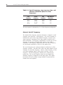
Each input path supports four different filter frequencies: 10Hz,
50Hz, 60Hz and 250Hz. The following table indicates autocalibration time based on the input path, and the selected filter
frequency.
Input Path 250Hz Filter
60Hz Filter
50Hz Filter
10Hz Filter
Low
181mS
384mS
435mS
1.85S
Mid
181mS
384mS
435mS
1.85S
High
96mS
208mS
238mS
1.03S
CJC sensors are acquired through the low voltage input path at
60Hz, to maximize the trade-offs between resolution and update rate.
Once every two minutes, the module calibrates one of the input path and
filter combinations on successive scans until all input path and filter
combinations that are used have been calibrated. During auto-calibration,
the module scan time will increase by the auto-calibration time.
Auto-calibration can be disabled by placing a one in any enabled channel’s
auto-cal disable bit.
32
SLC 500™ Universal Analog Input Module
Response to Slot
Disabling
By writing to the status file in the modular SLC processor, you can disable
any chassis slot. Refer to your SLC programming manual for the slot
disable/enable procedure.
!
CAUTION
POSSIBLE EQUIPMENT OPERATION
Always understand the implications of disabling a
module before using the slot disable feature.
Failure to observe this precaution can cause unintended
equipment operation.
Input Response
When a universal slot is disabled, the universal module continues to
update its input image table. However, the SLC processor does not
read input from a module that is disabled. Therefore, when the
processor disables the universal module slot, the module inputs
appearing in the processor image table remain in their last state, and
the module’s updated image table is not read. When the processor reenables the module slot, the current state of the module inputs are
read by the processor during the subsequent scan.
Output response
The SLC processor may change the universal module output data
(configuration) as it appears in the processor output image.
However, this data is not transferred to the universal module. The
outputs are held in their last state. When the slot is re-enabled, the
data in the processor image is transferred to the universal module.
Chapter 33
4
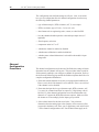
Chapter 4: Channel Configuration, Data, and Status
Channel Configuration, Data,
and Status
Read this chapter to:
• configure each input channel
• check each input channel’s configuration and status
Channel
Configuration
Channel configuration words appear in the SLC controller’s output image
table as shown below. Words 0-7 correspond to module channels 0-7.
After module installation, you must configure each channel to establish the
way the channel operates (e.g., input type, temperature units, etc.). You
configure the channel by setting bits in the configuration word using your
programmer. We present bit descriptions next.
SLC Output Image (Configuration) Words
15
O:e.0
Channel 0 Configuration Word
O:e.1
Channel 1 Configuration Word
O:e.2
Channel 2 Configuration Word
O:e.3
Channel 3 Configuration Word
O:e.4
Channel 4 Configuration Word
O:e.5
Channel 5 Configuration Word
O:e.6
Channel 6 Configuration Word
O:e.7
Channel 7 Configuration Word
0
e = slot number of the module
34
SLC 500™ Universal Analog Input Module
The configuration word default settings are all zero. Next, we describe
how you set configuration bits of a channel configuration word to set up
the following channel parameters:
• type of thermocouple , RTD, resistance, mV, V, or mA input
• RTD or resistance type of 2-wire, 3-wire or 4-wire
• data format such as engineering units, counts, or scaled for PID
• how the channel should respond to a detected open input circuit, if
applicable
• filter frequency selection
• temperature units in °C or °F
• whether the channel is enabled or disabled
• whether auto-calibration is enabled or disabled
• whether status or data information is selected for the module’s input
image table.
Channel
Configuration
Procedure
The channel configuration word consists of bit fields, the settings of which
determine how the channel will operate. This procedure looks at each bit
field separately and helps you configure a channel for operation. Refer to
the chart on the following page and the bit field descriptions that follow for
complete configuration information.
1. Determine which channels are used in your program and enable them.
Place a one in bit 0 if the channel is to be enabled. Place a zero in bit 0
if the channel is to be disabled.
2. Determine the input device type (thermocouple, RTD, resistance, mV,
V, or mA) for a channel and enter its respective 5-digit binary code in
bit field 1-5 of the channel configuration word. Remember that only
channels 4-7 support the RTD and resistance options. Make sure that
the shunts are set accordingly for the input types specified.
3. Select a data format for the data word value. Your selection
determines how the analog input value from the A/D converter will be
expressed in the data word. Enter your 2-digit binary code in bit field 67 of the channel configuration word. Not all data formats apply to all
Chapter 4: Channel Configuration, Data, and Status
35
input types. Check table 11 to make sure you selected a valid
combination.
4. Determine the desired state for the channel data word if an open circuit
condition is enabled and detected for that channel. Enter the 2-digit
binary code in bit field 8-9 of the channel configuration word. Not all
input types support open circuit detection. Review the “Open Circuit
State” description on page 43 to verify applicability.
5. If the channel is configured for thermocouple inputs, RTD or the CJC
sensor, determine if you want the channel data word to read in degrees
Fahrenheit or degrees Celsius and enter a one or a zero in bit 10 of the
configuration word. If the channel is configured for a mV, V, mA, or
resistance analog sensor, enter a zero in bit 9.
6. Determine the desired input filter frequency for the channel and enter
the 2-digit binary code in bit field 11-12 of the channel configuration
word. A lower filter frequency increases the channel update time, but
also increases the noise rejection and channel resolution. A higher
filter frequency decreases the channel update time, but also decreases
the noise rejection and effective resolution.
7. If an RTD or resistance input type was selected, enter the digit binary
code corresponding to 2- or 4-wire, or 3-wire, RTD inputs in bit 13. If
a thermocouple, mV, V, or mA type is used, enter a 0 in bit 13.
8. If auto-calibration is desired, place a zero in bit 14. If auto-calibration
is not desired, place a one in bit 14.
9. Determine whether the channel input image word should contain data
or status. Place a one in bit 15 if channel data is desired. Place a zero
in bit 15 if status is desired.
10. Build the channel configuration word for every channel on each
universal module repeating the procedures given in steps
1-9.
11.Enter this configuration into your ladder program and copy it to the
universal module.
Each channel has a word in the module’s output image which determines
the way that channel functions. Channels 0 through 3 may be configured
for current, voltage or thermocouple input types. No RTD or resistance
input types are allowed on those channels. Channels 4 through 7 may be
configured for current, voltage, thermocouple, RTD or resistance inputs.
The definition of the bits in the configuration words are described in the
charts below.
36
SLC 500™ Universal Analog Input Module
Table 4.1
Channel 3:0
Channel
Enable
Input
Type
Channel Configuration Word (O:e.3:0)
15 14 13 12 11 10
9
8
7
6
Channel disable
Channel enable
4 to 20 mA
0 to 20 mA
± 0.05 V
± 0.10 V
± 0.50 V
± 2.0 V
0 to 5 V
1 to 5V
0 to 10V
±10V
Thermocouple Type J
Thermocouple Type K
Theromcouple Type T
Thermocouple Type E
Thermocouple Type R
Thermocouple Type S
Thermocouple Type B
Thermocouple Type N
Invalid
Invalid
Invalid
Invalid
Thermocouple Type C
CJC
0
0
0
0
0
0
0
0
0
0
0
0
0
0
0
0
1
1
1
1
1
1
1
1
0
0
Data
Engineering Units x10
0
1
Format
Scaled for PID
1
0
1
1
Proportional counts
Open
Circuit
Zero on open circuit
Max. on open circuit
Min. on open circuit
Disabled
Temperature
Degrees C
0
Units
Degrees F
1
0
0
1
1
Channel
10 Hz input filter
0
0
filter
50 Hz input filter
0
1
freq.
60 Hz input filter
1
0
250 Hz input filter
1
1
Unused
0
Enabled
Disabled
Input Image
Type
Status word
Data word
4
3
2
1
0
0
1
Engineering Units x1
Auto-cal
5
0
1
0
1
0
1
0
1
0
0
0
0
0
0
0
0
1
1
1
1
1
1
1
1
0
0
0
0
1
1
1
1
0
0
0
0
1
1
1
1
0
0
0
0
1
1
1
1
0
0
0
1
0
1
1
1
0
0
1
1
0
0
1
1
0
0
1
1
0
0
1
1
0
0
1
x
x
0
1
1
0
1
0
1
0
1
0
1
0
1
0
1
0
1
0
1
0
1
x
x
x
x
0
1
Chapter 4: Channel Configuration, Data, and Status
Table 4.2
Channel 7:4
Channel
Enable
Input
Type
15 14
Channel Configuration Word (O:e.7:4)
13 12 11 10
9
8
7
6
Channel disable
Channel enable
4 to 20 mA
0 to 20 mA
± 0.05 V
± 0.10 V
± 0.50 V
± 2.0 V
0 to 5 V
1 to 5 V
0 to 10 V
±10V
Thermocouple Type J
Thermocouple Type K
Thermocouple Type T
Thermocouple Type E
Thermocouple Type R
Thermocouple Type S
Thermocouple Type B
Thermocouple Type N
RTD 100 Ω 385
RTD 200 Ω Pt 385
RTD 500 Ω Pt 385
RTD 1000 Ω Pt 385
RTD 100 Ω Pt 3916
RTD 200 Ω Pt 3916
RTD 500 Ω Pt 3916
RTD 1000 Ω Pt 3916
RTD 10 Ω Cu 426
RTD 120 Ω Ni 618
RTD 120 Ω Ni 672
Resistance 3000 Ω
Thermocouple Type C
CJC
0
0
0
0
0
0
0
0
0
0
0
0
0
0
0
0
1
1
1
1
1
1
1
1
1
1
1
1
1
1
1
1
Engineering Units x1
0
0
Engineering Units x10
0
1
Format
Scaled for PID
1
0
Proportional counts
1
1
Open
Circuit
Zero on open circuit
Max. on open circuit
Min. on open circuit
Disabled
Temperature
Degrees C
Units
Degrees F
Channel
10 Hz input filter
0
0
filter
50 Hz input filter
0
1
freq.
60 Hz input filter
1
0
0
0
1
1
1
1
Auto-cal
Enabled
Disabled
4
3
2
0
0
0
0
0
0
0
0
1
1
1
1
1
1
1
1
0
0
0
0
0
0
0
0
1
1
1
1
1
1
1
1
0
0
0
0
1
1
1
1
0
0
0
0
1
1
1
1
0
0
0
0
1
1
1
1
0
0
0
0
1
1
1
1
0
0
1
1
0
0
1
1
0
0
1
1
0
0
1
1
0
0
1
1
0
0
1
1
0
0
1
1
0
0
1
1
0
1
0
1
0
1
250 Hz input filter
2 or 4 wire
3 wire
5
1
0
0
1
Data
RTD Type
37
0
1
0
1
Input Image
Status word
0
Type
Data word
1
The configuration word default setting is all zeros. Whan a voltage or current input type is selected, the bit setting for
temperature units is ignored.
0
1
0
1
0
1
0
1
0
1
0
1
0
1
0
1
0
1
0
1
0
1
0
1
0
1
0
1
0
1
0
1
38
SLC 500™ Universal Analog Input Module
Select Channel Enable (Bit 0)
Use the channel enable bit to enable a channel. The universal module only
scans those channels that are enabled. To optimize module operation and
minimize throughput times, unused channels should be disabled by setting
the channel enable bit to zero.
When set (1) the channel enable bit is used by the module to read the
configuration word information you have selected. While the enable bit is
set, modification of the configuration word may lengthen the module
update time for one cycle. If any change is made to the configuration
word, the change will be reflected in the status word before new data is
valid (described in the last section of this chapter).
While the channel enable bit is cleared (0), the associated channel data/
status word values are cleared. After the channel enable bit is set, the
associated channel data/status word remains cleared until the universal
module sets the channel status bit (bit 0) in the channel status word.
Select Input Types (Bits 1-5)
The input type bit field lets you configure the channel for the type of input
device you have connected to the module. Valid input devices are types J,
K, T, E, R, S, B, N, and C thermocouple sensors, 100Ω, 200Ω, 500Ω, and
1000Ω Pt 385 RTDs; 100Ω, 200Ω, 500Ω, and 1000Ω Pt 3916 RTDs; 10Ω
Cu 426 RTD, 120Ω Ni 618 RTD, and 120Ω Ni 672 RTD sensors; 3000Ω
resistance devices and ±50mV, ± 100mV, ±500mV, ±2V, 0-5V, 1-5V, 010V, ±10V, 0-20mA, and 4-20mA analog input signals. The channel can
also be configured to read the cold-junction temperature calculated for that
specific channel. When the cold-junction compensation (CJC)
temperature is selected, the channel ignores the physical input signal.
RTD and resistance inputs can only be supported by channels 4-7.
Select Data Format (Bits 6 and 7)
The data format bit field lets you define the expressed format for the
channel data word contained in the module input image. The data types
are engineering units, scaled-for-PID, and proportional counts.
The engineering units allow you to select from two resolutions, x1 or
x10. For engineering units x1, values are expressed in 0.1 degrees,
0.01mV or 0.001mA. For engineering units x10, values are expressed in
1.0 degrees, 1mV or 0.01mA. (Use the x10 setting to produce
temperature readings in whole degrees Celsius or Fahrenheit.) You will
notice in Table 11 that not all input types can support the x1 format.
The scaled-for-PID value is the same for millivolt, milliamp,
thermocouple, RTD, resistance,) and CJC input types. The input signal
range is proportional to your selected input type and scaled into a 0-16,383
range, which is standard to the SLC PID algorithm.
Chapter 4: Channel Configuration, Data, and Status
39
The proportional counts are scaled to fit the defined temperature,
voltage, or current range. The input signal range is proportional to your
selected input and scaled into a (-32,768 to 32,767) range.
Using Scaled-for-PID and Proportional Counts
The universal module provides eight options for displaying input channel
data. These are 0.1°F, 0.1°C, 1°F, 1°C, 0.01 mV, 0.1 mV, Scaled-for-PID,
and Proportional Counts. The first six options represent real Engineering
Units provided/displayed by the 1746sc-NI8u, and do not require
explanation. The Scaled-for-PID and Proportional Counts selections
provide the highest NI8u display resolution, but also require you to
manually convert the channel data to real Engineering Units.
The equations below show how to convert from Scaled-for-PID to
Engineering Units, Engineering Units to Scaled-for-PID, Proportional
Counts to Engineering Units, and Engineering Units to Proportional
Counts. To perform the conversions, you must know the defined
temperature or millivolt range for the channel’s input type. Refer to the
Channel Data Word Format table on the following page. The lowest
possible value for an input type is SLOW, and the highest possible value is
S HIGH.
It is important to note that the Scaled for PID and proportional counts
format do not linearize inputs that are not linear. The module assumes that
current and voltage inputs are linear prior to insertion into the universal
module’s input stage. Thermocouple inputs are cold junction compensated,
and are linearized in their temperature conversion process through the
NIST ITS-90 tables. RTDs are converted from their resistance value to
degrees according to their associated IEC or JISC standards.
Scaling Examples
Scaled-for-PID to Engineering Units
Equation:
Engr Units Equivalent = SLOW + [(SHIGH-SLOW) x (Scaled-for-PID value displayed/16384)]
Assume type J input type, scaled-for-PID display type, channel data = 3421.
Want to calculate °C equivalent.
From Channel Data Word Format table, SLOW = -210°C and SHIGH = 760°C.
Solution:
Engr Units Equivalent = -210°C + [(760°C-(-210°C)) x (3421/16384)] = -7.46°C.
Engineering Units to Scaled-for-PID
Equation:
Scaled-for-PID Equivalent = 16384 x [(Engineering Units desired -SLOW)/(S HIGH-SLOW)]
Assume type J input type, scaled-for-PID display type, desired channel
temp. = 344°C.
Want to calculate Scaled-for-PID equivalent.
From Channel Data Word Format table, SLOW = -210°C and SHIGH = 760°C.
Solution:
Scaled-for-PID Equivalent = 16384 x [(344°C - (-210°C))/(760°C - (-210°C))] = 9357
40
SLC 500™ Universal Analog Input Module
Proportional Counts to Engineering Units
Equation:
Engr Units Equivalent = SLOW + {(SHIGH-SLOW) x [(Proportional Counts value displayed + 32768)/65536]}
Assume type E input type, proportional counts display type, channel data =
21567.
Want to calculate °F equivalent.
From Channel Data Word Format table, S LOW = -454°F an d SHIGH =1832°F
Solution:
Engr Units Equivalent = -454°F + {[1832°F -(-454°F)] x [(21567 + 32768)/65536]} = 1441.3°F
Engineering Units to Proportional Counts
Equation:
Proportional Counts Equivalent = {65536 x[(Engineering Units desired - SLOW)/(SHIGH-SLOW)]} -32768
Assume type E input type, proportional counts display type, desired channel
temp. = 1000°F.
Want to calculate Proportional Counts equivalent.
From Channel Data Word Format table, SLOW = -454°F and S HIGH = 1832°F.
Solution:
Proportional Counts Equivalent = {65536 x[{1000°F - (-454°F))/(1832°F - (-454°F))]} - 32768 = 8916.
Chapter 4: Channel Configuration, Data, and Status
41
Table 4.3 1746sc-NI8u Universal Module Channel Data Word Format
Data Format
Input
Type
Engineering Units x 10
° Celsius
° Fahrenheit
Engineering Units x 1
° Celsius
° Fahrenheit
Scaled-for-PID
Proportional
Counts
4-20 mA *
+400 to +2,000
+4,000 to +20,000
0 to 16,383
-32,768 to 32,767
0-20 mA *
0 to +2,000
+0 to +20,000
0 to 16,383
-32,768 to 32,767
± 0.05 V *
-500 to +500
-5,000 to +5,000
0 to 16,383
-32,768 to 32,767
± 0.10 V *
-1,000 to +1,000
-10,000 to +10,000
0 to 16,383
-32,768 to 32,767
± 0.50 V *
-5,000 to +5,000
N/A
0 to 16383
-32,768 to 32,767
± 2.0 V *
-2,000 to +2,000
-20,000 to +20,000
0 to 16,383
-32,768 to 32,767
0-5 V *
0 to +5,000
N/A
0 to 16,383
-32,768 to 32,767
1-5 V *
+1,000 to +5,000
N/A
0 to 16,383
-32,768 to 32,767
0-10 V *
0 to +10,000
N/A
0 to 16,383
-32,768 to 32,767
±10 V *
-10,000 to +10,000
N/A
0 to 16,383
-32,768 to 32,767
J
-210 to 760
-346 to 1,400
-2,100 to 7,600
-3,460 to 14,000
0 to 16,383
-32,768 to 32,767
K
-270 to 1,370
-454 to 2,498
-2,700 to 13,700
-4,540 to 24,980
0 to 16,383
-32,768 to 32,767
T
-270 to 400
-454 to 752
-2,700 to 4,000
-4,540 to 7,520
0 to 16,383
-32,768 to 32,767
E
-270 to 1,000
-454 to 1,832
-2,700 to 10,000
-4,540 to 18,320
0 to 16,383
-32,768 to 32,767
R
0 to 1,768
32 to 3,214
0 to 17,680
320 to 32,140
0 to 16,383
-32,768 to 32,767
S
0 to 1,768
32 to 3,214
0 to 17,680
320 to 32,140
0 to 16,383
-32,768 to 32,767
B
300 to 1,820
572 to 3,308
3,000 to 18,200
5,720 to 32,767**
0 to 16,383
-32,768 to 32,767
N
0 to 1,300
32 to 2,372
0 to 13,000
320 to 23,720
0 to 16,383
-32,768 to 32,767
C
0 to 2315
32 to 4199
0 to 23,150
32 to 32767**
0 to 16,383
-32, 768 to 32-767
10Ω Cu 426
-100 to 260
-148 to 500
-1,000 to 2,600
-1,480 to 5,000
0 to 16,383
-32, 768 to 32-767
120 Ω Ni 618
-100 to 260
-148 to 500
-1,000 to 2,600
-1,480 to 5,000
0 to 16,383
-32, 768 to 32-767
120 Ω Ni 672
-80 to 260
-112 to 500
-800 to 2,600
-1,120 to 5,000
0 to 16,383
-32, 768 to 32-767
3000Ω*
0 to 3,000
0 to 30,000
0 to 16,383
-32, 768 to 32-767
100Ω Pt 385
-200 to 850
-328 to 1,562
-2,000 to 8,500
-3,280 to 15,620
0 to 16,383
-32,768 to 32,767
200Ω Pt 385
-200 to 750
-328 to 1,382
-2,000 to 7,500
-3,280 to 13,820
0 to 16,383
-32,768 to 32,767
500Ω Pt 385
-200 to 850
-328 to 1,562
-2,000 to 8,500
-3,280 to 15,620
0 to 16,383
-32,768 to 32,767
1,000Ω Pt 385
-200 to 850
-328 to 1,562
-2,000 to 8,500
-3,280 to 15,620
0 to 16,383
-32,768 to 32,767
100Ω Pt 3916
-200 to 630
-328 to 1,166
-2,000 to 6,300
-3,280 to 11,660
0 to 16,383
-32,768 to 32,767
200Ω Pt 3916
-200 to 630
-328 to 1,166
-2,000 to 6,300
-3,280 to 11,660
0 to 16,383
-32,768 to 32,767
500Ω Pt 3916
-200 to 630
-328 to 1,166
-2,000 to 6,300
-3,280 to 11,660
0 to 16,383
-32,768 to 32,767
1,000Ω Pt 3916
-200 to 630
-328 to 1,166
-2,000 to 6,300
-3,280 to 1,1660
0 to 16,383
-32,768 to 32,767
CJC
-25 to 105
-13 to 221
-250 to 1,050
-130 to 2,210
0 to 16,383
-32,768 to 32,767
* When current, voltage, or resistance input types are selected, the temperature setting is ignored and does not affect the data format.
** When Type B or Type C thermocouples cannot be represented in engineering units x 1 in °F above 3276.6°F, the module’s software will treat it as an
over range condition if that channel has input to full scale.
42
SLC 500™ Universal Analog Input Module
Table 4.4
1746sc-NI8u Thermocouple Module Channel Data Word Resolution
Data Format
Input
Type
Engineering Units x 10
° Celsius
° Fahrenheit
Engineering Units x 1
° Celsius
° Fahrenheit
Scaled-for-PID
° Celsius
° Fahrenheit
Proportional Counts
° Celsius
° Fahrenheit
0-20mAn
0.01mA/step
0.01mA/step
0.001mA/step
0.001mA/step
1.221µA/step
1.221µA/step
0.3052µA/step
0.3052µA/step
4-20mAn
0.01mA/step
0.01mA/step
0.001mA/step
0.001mA/step
0.9766µA/step
0.9766µA/step
0.2441µA/step
0.2441µA/step
±0.05Vn
0.1mV/step
0.1mV/step
0.01mV/step
0.01mV/step
6.104µV/step
6.104µV/step
1.526µV/step
1.526µV/step
±0.100Vn
0.1mV/step
0.1mV/step
0.01mV/step
0.01mV/step
12.21µV/step
12.21µV/step
3.052µV/step
3.052µV/step
±0.5Vn
0.1mV/step
0.1mV/step
N/A
N/A
61.04µV/step
61.04µV/step
15.26µV/step
15.26µV/step
±2.0Vn
0.001V/step
0.001V/step
0.01mV/step
0.01mV/step
244.1µV/step
244.1µV/step
61.04µV/step
61.04µV/step
0-5Vn
0.001V/step
0.001V/step
N/A
N/A
305.2µV/step
305.2µV/step
76.29µV/step
76.29µV/step
1-5Vn
0.001V/step
0.001V/step
N/A
N/A
244.1µV/step
244.1µV/step
61.04µV/step
61.04µV/step
0-10Vn
0.001V/step
0.001V/step
N/A
N/A
610.4µV/step
610.4µV/step
152.6µV/step
152.6µV/step
±10Vn
0.001V/step
0.001V/step
N/A
N/A
1.221mV/step
1.221mV/step
305.2µV/step
305.2µV/step
100Ω Pt 385
1°C/step
1°F/step
0.1°C/step
0.1°F/step
0.06409°C/step 0.01154°F/step 0.01602°C/step 0.02884°F/step
200Ω Pt 385
1°C/step
1°F/step
0.1°C/step
0.1°F/step
0.06409°C/step 0.01154°F/step 0.01602°C/step 0.02884°F/step
500Ω Pt 385
1°C/step
1°F/step
0.1°C/step
0.1°F/step
0.06409°C/step 0.01154°F/step 0.01602°C/step 0.02884°F/step
1,000Ω Pt 385
1°C/step
1°F/step
0.1°C/step
0.1°F/step
0.06409°C/step 0.01154°F/step 0.01602°C/step 0.02884°F/step
100Ω Pt 3916
1°C/step
1°F/step
0.1°C/step
0.1°F/step
0.05066°C/step 0.09119°F/step 0.01266°C/step 0.02280°F/step
200Ω Pt 3916
1°C/step
1°F/step
0.1°C/step
0.1°F/step
0.05066°C/step 0.09119°F/step 0.01266°C/step 0.02280°F/step
500Ω Pt 3916
1°C/step
1°F/step
0.1°C/step
0.1°F/step
0.05066°C/step 0.09119°F/step 0.01266°C/step 0.02280°F/step
1,000Ω Pt 3916
1°C/step
1°F/step
0.1°C/step
0.1°F/step
0.05066°C/step 0.09119°F/step 0.01266°C/step 0.02280°F/step
10Ω Cu 426
1°C/step
1°F/step
0.1°C/step
0.1°F/step
0.0220°C/step
0.0396°F/step
0.0055°C/step 0.00990°F/step
120Ω Ni 618
1°C/step
1°F/step
0.1°C/step
0.1°F/step
0.0220°C/step
0.0396°F/step
0.0055°C/step 0.00990°F/step
120Ω Ni 672
1°C/step
1°F/step
0.1°C/step
0.1°F/step
0.0208°C/step
0.0374°F/step
0.0052°C/step 0.00993°F/step
3,000Ω
1Ω/step
1Ω/step
0.1Ω/step
0.1Ω/step
0.183Ω/step
0.183Ω/step
0.0458Ω/step
0.0458Ω/step
J
1°C/step
1°F/step
0.1°C/step
0.1°F/step
0.0592°C/step
0.1066°F/step
0.0148°C/step
0.0266°F/step
K
1°C/step
1°F/step
0.1°C/step
0.1°F/step
0.1001°C/step
0.1802°F/step
0.0250°C/step
0.0450°F/step
T
1°C/step
1°F/step
0.1°C/step
0.1°F/step
0.0409°C/step
0.0736°F/step
0.0102°C/step
0.0184°F/step
E
1°C/step
1°F/step
0.1°C/step
0.1°F/step
0.0775°C/step
0.1395°F/step
0.0194°C/step
0.0349°F/step
R
1°C/step
1°F/step
0.1°C/step
0.1°F/step
0.1079°C/step
0.1942°F/step
0.0270°C/step
0.0486°F/step
S
1°C/step
1°F/step
0.1°C/step
0.1°F/step
0.1079°C/step
0.1942°F/step
0.0270°C/step
0.0486°F/step
B
1°C/step
1°F/step
0.1°C/step
0.1°F/step
0.0928°C/step
0.1670°F/step
0.0232°C/step
0.0417°F/step
N
1°C/step
1°F/step
0.1°C/step
0.1°F/step
0.0793°C/step
0.1428°F/step
0.0198°C/step
0.0357°F/step
C
1°C/step
1°F/step
0.1°C/step
0.1°F/step
0.1413°C/step
0.2543°F/step
0.0353°C/step
0.0636°F/step
CJC
Sensor
1°C/step
1°F/step
0.1°C/step
0.1°F/step
0.0079°C/step
0.0143°F/step
0.0020°C/step
0.0036°F/step
n When millivolts or resistance are selected, the temperature setting is ignored. Analog input data is the same for either °C or °F selection.
Chapter 4: Channel Configuration, Data, and Status
43
Important: Data resolution is not equivalent to data accuracy. Data
resolution merely indicates what a bit-weight is in any given
input type and data format combination. Input accuracy of
±50µV may span multiple steps for PID and Proportional
Counts data types. As an example a Type B thermocouple
temperature range of 0 to 1820°C provides a voltage input
range of 0 to 13.82mV to the NI8u. This is a very small
input range and when it is scaled to PID or proportional
counts ranges a small input change will result in many
counts being changed.
Select Open Circuit State (Bits 8 and 9)
The open-circuit bit field lets you define the state of the channel data word
when an open-circuit condition is detected for that channel. The open
circuit does not apply to the 0-5V, 1-5V, 0-10V, ±2V, ±10V, or 0-20mA
input types and should be disabled when those types are selected, or else a
configuration error will result. It can be enabled for all other types,
including the CJC input. This feature can be disabled by selecting the
disable option.
An open circuit condition occurs when the input path is physically
separated or open. For thermocouples or RTDs, either the sensor or the
extension wire may be broken. The voltage or current input wire may be
cut or disconnected from the terminal block. For RTDs only, a short
circuit of less than 3 ohms will also flag this error.
If either of the two CJC devices are removed from the module wiring
terminal, any input channel configured for either a thermocouple or CJC
temperature input will be placed in an open circuit condition. An input
channel configured for millivolt, volt, milliamp, or RTD input is not affected
by CJC open-circuit conditions.
The results of the data word in an open-circuit condition depend upon the
selection of bits 8 and 9.
If zero is selected, the channel data word is forced to 0 during an opencircuit condition.
Selecting maximum forces the channel data word value to its full scale
value during an open-circuit condition. The full scale value is determined
by the selected input type and data format.
Selecting minimum forces the channel data word value to its low scale
value during an open-circuit condition. The low scale value is determined
by the selected input type and data format.
When the open-circuit option applies, disabling the open-circuit selection
may result in unintended operation on a failure because the returned data
word value is unknown. The open circuit error bit and the channel LED
will flag the condition until the error is resolved.
44
SLC 500™ Universal Analog Input Module
For example, if channel one is configured as a thermocouple type when
the CJC breaks in an open-circuit condition, if open-circuit detection is
disabled, the data word will remain unchanged. If the circuit selection is
set at minimum, the data word will be set to the low scale value for the
range and format.
Select Temperature Units (Bit 10)
The temperature units bit lets you select temperature engineering units for
thermocouple, RTD, and CJC input types. Units are either degrees
Celsius (°C) or degrees Fahrenheit (°F). This bit field is only active for
thermocouple, RTD and CJC input types. It is ignored when millivolt or
current inputs types are selected.
Select Channel Filter Frequency (Bits 11 and 12)
The channel filter frequency bit field lets you select one of four filters
available for a channel. The filter frequency affects the channel update
time and noise rejection characteristics. A smaller filter frequency
increases the channel update time, but also increases the noise rejection
and channel resolution. A larger filter frequency decreases the noise
rejection, but also decreases the channel update time and channel
resolution.
• 250 Hz setting provides minimal noise filtering.
• 60 Hz setting provides 60 Hz AC line noise filtering.
• 50 Hz setting provides 50 Hz AC line noise filtering.
• 10 Hz setting provides both 50 Hz and 60 Hz AC line noise filtering.
When a CJC input type is selected, this field is ignored. To maximize the
speed versus resolution trade-off, CJC inputs are sampled at 60 Hz.
Select RTD Type (Bit 13)
The selection for RTD or resistance type is only valid for channels 4
through 7, and should be set to zero for channels 0 through 3.
If the Input Type selection defines an RTD or resistance type, then the
wire type also needs to be specified. The universal module converts the
RTD or resistance type input data differently according to whether the 2
or 4 wire method is used, or the 3 wire method is used.
Select Auto-Calibration Disable (Bit 14)
The auto-calibration disable bit allows you to disable periodic autocalibration. Set this bit on any enabled channel to disable auto-calibration
for all channels. Clear this bit on all enabled channels to enable autocalibration on all channels.
Chapter 4: Channel Configuration, Data, and Status
45
Select Input Image Type (Bit 15)
The input image type bit allows you to select data or status information in
the channel’s input image word. When set (1) the module places channel
data in the corresponding input image word. When the bit is cleared (0)
the module places channel status in the corresponding input image word.
Channel Data/Status
Word
The actual thermocouple, RTD, resistance, millivolt, volt, or milliamp input
data values or channel status reside in I:e.0 through I:e.7 of the universal
module input image file. The data values present will depend on the input
type and data formats you have selected. When an input channel is
disabled, its data word is reset (0).
Module Input Image (Data/Status) Words
15
O:e.0
Channel 0 Channel Data/Status Word
O:e.1
Channel 1 Channel Data/Status Word
O:e.2
Channel 2 Channel Data/Status Word
O:e.3
Channel 3 Channel Data/Status Word
O:e.4
Channel 4 Channel Data/Status Word
O:e.5
Channel 5 Channel Data/Status Word
O:e.6
Channel 6 Channel Data/Status Word
O:e.7
Channel 7 Channel Data/Status Word
Channel Status
Checking
0
The input image of the module is 8 words. Since there are 8 channels
with a data word and a status word for each channel, the input image
information is multiplexed. The information in the input image is the
channel data word if bit 15 of the channel’s configuration word is 1. The
information in the input image is the channel status word if bit 15 of the
channel’s configuration word is 0.
You can use the information provided in the status word to determine if the
input configuration data for any channel is valid per your configuration in
O:e.0 through O:e.7.
46
SLC 500™ Universal Analog Input Module
The channel status can be analyzed bit by bit. In addition to providing
information about an enabled or disabled channel, each bit’s status (0 or 1)
tells you how the input data from the analog sensor connected to a
specific channel will be translated for your application. The bit status also
informs you of any error condition and can tell you what type of error
occurred.
The status word definitions for channels 0 through 3 do not include the
RTD or resistance support that is provided by channels 4 through 7. The
charts on the following pages provide a bit by bit examination of the
respective status words.
Table 4.5
Channel 3:0
Channel
Status
Input
Type
Data
Format
Open
Circuit
Channel
filter
freq.
Open circuit
Under range
error
Over range
error
Channel
error
Channel 0-7 Status Word (I:e.0 through
I:e.7) - Bit Definitions
15 14 13 12 11 10
Channel disabled
Channel enable
4 to 20 mA
0 to 20 mA
± 0.05 V
± 0.10 V
± 0.50 V
± 2.0 V
0 to 5 V
1 to 5V
0 to 10V
±10V
Thermocouple Type J
Thermocouple Type K
Theromcouple Type T
Thermocouple Type E
Thermocouple Type R
Thermocouple Type S
Thermocouple Type B
Thermocouple Type N
Invalid
Invalid
Invalid
Invalid
Thermocouple Type C
CJC temperature
Engineering Units x1
Engineering Units x10
Scaled for PID
Proportional counts
Zero on open circuit
Max. on open circuit
Min. on open circuit
Disabled
10 Hz input filter
50 Hz input filter
60 Hz input filter
250 Hz input filter
No error
Open circuit detected
No error
Under range condition
No error
Over range condition
No error
Channel error
9
8
7
6
5
0
0
0
0
0
0
0
0
0
0
0
0
0
0
0
0
1
1
1
1
1
1
1
1
0
0
1
1
0
0
1
1
0
0
1
1
0
1
0
1
0
1
0
1
0
1
0
1
0
1
0
1
0
1
0
1
4
0
0
0
0
0
0
0
0
1
1
1
1
1
1
1
1
0
0
0
0
1
1
1
1
3
0
0
0
0
1
1
1
1
0
0
0
0
1
1
1
1
0
0
0
1
0
1
1
1
2
0
0
1
1
0
0
1
1
0
0
1
1
0
0
1
1
0
0
1
x
x
0
1
1
1
0
1
0
1
0
1
0
1
0
1
0
1
0
1
0
1
0
1
x
x
x
x
0
1
0
0
1
Chapter 4: Channel Configuration, Data, and Status
Channel 7:4
Channel
Status
Input
Type
15 14 13 12 11 10
9
8
7
6
Channel disabled
Channel enable
4 to 20 mA
0 to 20 mA
± 0.05 V
± 0.10 V
± 0.50 V
± 2.0 V
0 to 5 V
1 to 5 V
0 to 10 V
±10V
Thermocouple Type J
Thermocouple Type K
Thermocouple Type T
Thermocouple Type E
Thermocouple Type R
Thermocouple Type S
Thermocouple Type B
Thermocouple Type N
RTD 100 Ω 385
RTD 200 Ω Pt 385
RTD 500 Ω Pt 385
RTD 1000 Ω Pt 385
RTD 100 Ω Pt 3916
RTD 200 Ω Pt 3916
RTD 500 Ω Pt 3916
RTD 1000 Ω Pt 3916
RTD 10 Ω Cu 426
RTD 120 Ω Ni 618
RTD 120 Ω Ni 672
Resistance 3000 Ω
Thermocouple Type C
CJC temperature
0
0
0
0
0
0
0
0
0
0
0
0
0
0
0
0
1
1
1
1
1
1
1
1
1
1
1
1
1
1
1
1
0
0
Data
Engineering Units x10
0
1
Format
Scaled for PID
1
0
1
1
Proportional counts
Open
Circuit
Zero on open circuit
Max. on open circuit
Min. on open circuit
Disabled
Channel
10 Hz input filter
0
0
filter
50 Hz input filter
0
1
Open circuit
0
0
1
1
60 Hz input filter
1
0
250 Hz input filter
1
1
No error
0
Open circuit detected
1
Under range
No error
error
Over range
error
Channel
error
Under range condition
No error
Over range condition
No error
Channel error
4
3
2
1
0
0
1
Engineering Units x1
freq.
5
47
0
1
0
1
0
1
0
1
0
1
0
0
0
0
0
0
0
0
1
1
1
1
1
1
1
1
0
0
0
0
0
0
0
0
1
1
1
1
1
1
1
1
0
0
0
0
1
1
1
1
0
0
0
0
1
1
1
1
0
0
0
0
1
1
1
1
0
0
0
0
1
1
1
1
0
0
1
1
0
0
1
1
0
0
1
1
0
0
1
1
0
0
1
1
0
0
1
1
0
0
1
1
0
0
1
1
0
1
0
1
0
1
0
1
0
1
0
1
0
1
0
1
0
1
0
1
0
1
0
1
0
1
0
1
0
1
0
1
48
SLC 500™ Universal Analog Input Module
Important: If the channel for which you are seeking status is disabled,
all bit fields are cleared. The status word for any disabled
channel is always 0000 0000 0000 0000 regardless of any
previous setting that may have been made to the
configuration word.
Explanations of the status conditions follow.
Channel Status (Bit 0)
The channel status bit indicates operational state of the channel. When
the channel enable bit is set in the configuration word (bit 0), the universal
module configures the selected channel and takes a data sample for the
channel data word before setting this bit in the status word.
Input Type Status (Bits 1-5)
The input type bit field indicates what type of input signal you have
configured for the channel. This field reflects the input type defined in the
channel configuration word.
Data Format Type Status (Bits 6 and 7)
The data format bit field indicates the data format you have defined for
the channel. This field reflects the data type selected in bits 6 and 7 of the
channel configuration word.
Open Circuit Type Status (Bits 8 and 9)
The open-circuit bit field indicates how you have defined the open circuit
bits configuration word, and therefore, the response of the universal
module to an open-circuit condition. This feature does not apply to the 0-5
V, 1-5 V, 0-10 V, ±2 V, ±10 V, or 0-20mA input ranges, and a properly
configured channel of those types will give the disabled status. It applies
to all others, including CJC temperature input.
Channel Filter Frequency (Bits 10 and 11)
The channel filter frequency bit field reflects the filter frequency you
selected in the configuration word.
Open Circuit Error (Bit 12)
This bit is set (1) whenever a configured channel detects an open-circuit
condition at its input. Short circuited RTD inputs will also flag this error
condition. A short circuit for RTDs exist when the module reads less than
3 ohms across the RTD input. An open-circuit at the CJC sensor will also
flag this error if the channel input type is either thermocouple or CJC
temperature. A range error on the CJC sensor will also flag this bit if the
input type is a thermocouple type.
Chapter 4: Channel Configuration, Data, and Status
49
Under-Range Error (Bit 13)
This bit is set (1) whenever a configured channel detects an under-range
condition for the channel data. An under-range condition exists when the
input value is equal to or below the specified lower limit of the particular
sensor connected to that channel.
Over-Range Error (Bit 14)
This bit is set (1) whenever a configured channel detects an over-range
condition for the channel data. An over-range condition exists when the
input value is equal to or above the specified upper limit of the particular
sensor connected to that channel.
Channel Error (Bit 15)
This bit is set (1) whenever a configured channel detects an error in the
configuration word, or an error has occurred while acquiring the ADC
data value. If during the auto-calibration process, the module detects an
out-of-range condition for the filter frequency selected for the channel, the
channel error bit will be set. An out-of-range condition occurring during
auto-calibration would be the result of an overly noisy environment,
whereby the module cannot maintain accuracy specifications, thus flagging
an error. The error bit is cleared when the error condition is resolved.
The channel data word is still updated during a period of auto-calibration
filter frequency tolerance errors, but accuracy may be degraded.
50
SLC 500™ Universal Analog Input Module
Chapter 51
5
Chapter 5: Ladder Program Examples
Programming Examples
Earlier chapters explained how the configuration word defines the way a
channel operates. This chapter shows the programming required to
enter the configuration word into the processor memory. It also
provides you with segments of ladder logic specific to unique situations
that might apply to your programming requirements. The example
segments include:
• initial programming of the configuration word
• dynamic programming of the configuration word
• verifying channel configuration changes
• interfacing the universal module to a PID instruction
• monitoring channel status bit
Initial Programming
To enter data into the channel configuration word (O:e.0 through O:e.7)
when the channel is disabled (bit 0 = 0), follow these steps. Refer to
page 30 (Table 9) for specific configuration details.
Example - Configure eight channels of a universal module residing in
slot 3 of a 1746 chassis. Configure each channel with the same
parameters.
Figure 5.1
Channel configuration
15
14
13
12
11
10
9
8
7
6
5
4
3
2
1
0
1
0
0
0
0
0
1
1
0
1
0
1
0
0
1
1
Configure Channel For:
Channel Enable Bit
± 10.0 V Range
Engineering Units x 10
Open Circuit Disabled
Degrees C (N/A)
10 Hz Filter
RTD Type (N/A)
Auto-cal Disable Bit
Channel Data Word
This example transfers configuration data and sets the channel enable
bits of all eight channels with a single File Copy instruction.
52
SLC 500™ Universal Analog Input Module
Procedure
1. Using the memory map function, create integer file N10. Integer file
N10 should contain eight elements (N10:0 through N10:7).
2. Using the APS software data monitor function, enter the
configuration parameters for all eight universal channels into a source
integer data file N10.
Figure 5.2
address 15
N10:0
0000
N10:3
0000
N10:4
0000
N10:5
0000
N10:6
0000
N10:7
0000
Data table for initial programming
0010
0010
0010
0010
0010
0010
data
0010
0010
0010
0010
0010
0010
0
0011
0011
0011
0011
0011
0011
address
15
data
Press a key or enter value
N10:3/0 = 1
offline
no forces
binary data
CHANGE
RADIX
SPECIFY
ADDRESS
NEXT
FILE
PREV
FILE
F1
F5
F7
F8
decimal addr
0
File EXMPL
3. Program a rung in your ladder logic to copy the contents of integer
file N10 to the eight consecutive output words of the universal
module beginning with O:3.0.
Figure 5.3
First Pass Bit
s:1
]
[
15
Initial programming example
Initialize Module
COP
COPY FILE
Source
#N10:0
Length
8
Dest
#O:3.0
On power up, bit S:1/15 is set for the first program scan, and integer file N10
is sent to the NI8u channel configuration words.
53
Chapter 5: Ladder Program Examples
Dynamic
Programming
The following example explains how to change data in the channel
configuration word when the channel is currently enabled.
Example - Execute a dynamic configuration change to channel 2 of the
universal module located in slot 3 of a 1746 chassis. Change from
monitoring a bipolar 10 V signal to monitoring the CJC sensors
mounted on the terminal block. This gives a good indication of what
the temperature is inside the control cabinet. Finally, set channel 2 back
to the bipolar 10 V range.
Figure 5.4
Dynamic programming example
Program Listing
Rung 2:0
Rung 2:1
Set up all eight channels
s:1
] [
15
Set channel 2 to CJC
s:1
B3
] [ { OSR ]
0
0
COP
COPY FILE
Source #N10:0
Dest
#O:3.0
Length
8
MOV
MOVE
Source N10:8
Dest
Rung 2:2
Set channel 2 back ±10V
I:1.0 B3
]/[ { OSR ]
0
1
MOV
MOVE
Source N10:2
Dest
Rung 2:3
I ENDI
O:3.2
O:3.2
54
SLC 500™ Universal Analog Input Module
Figure 5.5
address
N10:0
N10:1
N10:2
N10:3
N10:4
N10:5
N10:6
N10:7
15
1000
1000
1000
1000
1000
1000
1000
1000
data
0011 0101
0011 0101
0011 0101
0011 0101
0011 0101
0011 0101
0011 0101
0011 0101
Data table for dynamic programming
0
0011
0011
0011
0011
0011
0011
0011
0011
address
N10:8
15
data
0
1000 0000 0111 1111
Important: While the module performs the configuration alteration, it
does not monitor input device data change at any channel.
Verifying Channel
Configuration
Changes
When executing a dynamic channel configuration change, there will
always be a delay from the time the ladder program makes the change
to the time the NI8u gives you a data word using that new configuration
information. Therefore, it is very important to verify that a dynamic
channel configuration change took effect in the module, particularly if
the channel being dynamically configured is used for control. The
following example explains how to verify that channel configuration
changes have taken effect.
Example - Execute a dynamic configuration change to channel 2 of the
universal module located in slot 3 of a 1746 chassis, and set an internal
“data valid” bit when the new configuration has taken effect. In this
example the input image of the channel is selected to contain the
channel status word.
55
Chapter 5: Ladder Program Examples
Figure 5.6
Programming for configuration changes
example
Rung 2:0
Set up all eight channels
s:1
] [
15
Rung 2:1
Set channel 2 to CJC
I:1.0
B3
] [
{ OSR ]
0
0
Rung 2:2
COP
COPY FILE
Source
#N10:0
Dest
#O:3.0
Length
8
Set channel 2 back to ±10V
I:1.0
B3
]/[
{ OSR ]
0
1
MOV
MOVE
Source
N10:8
Dest
O:3.2
MOV
MOVE
Source
N10:2
Dest
O:3.2
Check that the configuration written to channel two
is being echoed back in channel two's status word.
Rung 2:3
EQU
EQUAL
Source
A I:3.2
Source
B O:3.2
B3
( )
3
Rung 2:4
I END I
Figure 5.7
Data table for configuration changes
Data Table
address
N10:0
N10:1
N10:2
N10:3
N10:4
N10:5
N10:6
N10:7
15
1000
1000
1000
1000
1000
1000
1000
1000
data
0011 0101
0011 0101
0011 0101
0011 0101
0011 0101
0011 0101
0011 0101
0011 0101
0
0011
0011
0011
0011
0011
0011
0011
0011
address
N10:8
15
data
0
0000 0000 0111 1111
56
SLC 500™ Universal Analog Input Module
Interfacing to the PID
Instruction
The universal module was designed to interface directly to the SLC
5/02™ or later processor PID instruction without the need for an
immediate scale operation.
Example - Use NI8u channel data as the process variable in the PID
instruction.
1. Select scaled-for-PID as the data type in the channel configuration
word.
2. Specify the input channel data word as the process variable for the
PID instruction.
In this example, the value -32,617 is the numeric equivalent of
configuration word N10:0 for channel 0. It is configured for a type K
thermocouple, scaled-for-PID, zero the signal for an open circuit, 10
Hz, °C, channel enabled, to return the data word.
Figure 5.8
Programming for PID Control Example
Program Listing
Rung 2:0
Rung 2:1
First Pass Bit
Initialize NI8u
Channel 0
MOV
MOVE
Source
N10:0
-32,617
Dest
O:3.0
0
s:1
] [
15
PID
PID
Control
Process
Control
Control
Rung 2:2
Block
N11:0
Variable
I:3.0
Variable
N11:23
Block Length
23
SCL
SCALE
Source
N11:23
Rate [/10000]
Offset
Dest
The Rate and Offset parameters should be set per
your application. The Dest will typically be an
analog output channel. Refer to the APS User Manual
or Analog I/O Modules User Manual for specific
examples of the SLC instruction.
Rung 2:3
I END I
57
Chapter 5: Ladder Program Examples
Figure 5.9
Data table for PID Control
Data Table
address
N10:0
Monitoring Channel
Status Bits
15
data
0
1000 0000 1001 0111
address
15
data
0
The example shows how you could monitor the open circuit error bits of
each channel and set an alarm in the processor if one of the inputs
opens. An open circuit error can occur if one of the input signal wires
gets cut or disconnected from the terminal block, or if the CJC sensors
are not installed or are damaged.
Important: If a CJC input is not installed or is damaged, all
thermocouple alarms are set, and their respective channel LEDs blink.
58
SLC 500™ Universal Analog Input Module
Figure 5.10
Rung 2:0
Monitoring channel status bits example
Program Listing
First Pass Bit
Initialize NI8u
Channel 0
COP
COPY FILE
Source
#N10:0
Dest
#O:3.0
Length
8
s:1
] [
15
Rung 2:1
Channel 0
Enable
I:3.0
] [
0
Channel 0
Open
I:3.0
] [
12
Channel 0
Alarm
O:2.0
( )
0
Rung 2:2
Channel 1
Enable
I:3.1
] [
0
Channel 1
Open
I:3.1
] [
12
Channel 1
Alarm
O:2.0
( )
1
Rung 2:3
Channel 2
Enable
I:3.2
] [
0
Channel 2
Open
I:3.2
] [
12
Channel 2
Alarm
O:2.0
( )
2
Rung 2:4
Channel 3
Enable
I:3.3
] [
0
Channel 3
Open
I:3.3
] [
12
Channel 3
Alarm
O:2.0
( )
3
Rung 2:5
Channel 4
Enable
I:3.4
] [
0
Channel 4
Open
I:3.4
] [
12
Channel 4
Alarm
O:2.0
( )
4
Rung 2:6
Channel 5
Enable
I:3.5
] [
0
Channel 5
Open
I:3.5
] [
12
Channel 5
Alarm
O:2.0
( )
5
Rung 2:7
Channel 6
Enable
I:3.6
] [
0
Channel 6
Open
I:3.6
] [
12
Channel 6
Alarm
O:2.0
( )
6
Rung 2:8
Channel 7
Enable
I:3.7
] [
0
Channel 7
Open
I:3.7
] [
12
Channel 7
Alarm
O:2.0
( )
7
Figure 5.11
Data table for monitoring channel status
bits
Data Table
address
N10:0
N10:1
N10:2
N10:3
15
0000
0000
0000
0000
data
0000 1001
0000 1001
0000 1001
0000 1001
0
0111
0111
0111
0111
address
N10:4
N10:5
N10:6
N10:7
15
0000
0000
0000
0000
data
0000 1001
0000 1001
0000 1001
0000 1001
0
0111
0111
0111
0111
59
Chapter 5: Ladder Program Examples
This is an example of how to automatically switch between reading the
channel status words and channel data words. Specifically, this
example shows a very simple method of utilizing a timer to periodically
switch between reading the channel status and data words.
The program utilizes a timer accumulator value to determine when to
set up the configuration words, and when to read in the channel status
and channel data information. The channel status information is copied
from the I:2.0 to I:2.7 registers into registers N7:10 to N7:17. The
channel data information is copied from I:2.0 to I:2.7 into registers N7:0
to N7:7. This allows sensor data and channel status information to be
accessed at any time from these registers. However, when the module
channels are configured to read sensor data, the channel status words
(as reflected in N7:10 to N7:17) are not being dynamically updated, and
vice-versa.
A longer interval between reading in the channel status information
could be achieved through the utilization of a combination of counters
and timers. If you are utilizing an SLC 5/03 or SLC 5/04 or later
processor, the internal processor clock registers S:40 to S:42 could be
utilized to determine the timing.
Rung 2:0
TON
TIMER ON DELAY
Timer
T4:0
Timer Base
0.01
Preset
1001
Accum
0
(EN)
(DN)
Timer T4:0 counts out a 10 second interval. Its accumulator indicates
the progress it has made toward completion. The accumulator value
shall be utilized to determine when to set the channel configuration
word to send sensor data or to send status information.
A longer interval between transitions can be achieved using a
combination of timers and counters.
60
SLC 500™ Universal Analog Input Module
Rung 2:1
This rung tests to see if T4:0.ACC is at a value between 800 and 950
counts. If so, the channel configuration words are defined (through the
Fill File command) to send status information.
LIM
LIMIT TEST
Low Lim
Test
800
T4:0.ACC
0
High Lim
FLL
FILL FILE
Source
151
Dest
#O:2.0
Length
8
950
Rung 2:2
This rung executes a Copy File command to move the channel status
word (as enabled in the previous rung) into registers N7:10 through
N7:17 for all channels.
Though the module is quick about switching from sensor data to status
information, it is a good idea to give the module a little time to switch
modes. That is why this example uses a half second period in time
between when the channel is set-up to send the status word and when
the status word is read into the N7 table.
LIM
LIMIT TEST
Low Lim
Test
950
T4:0.ACC
0
High Lim
1000
COP
COPY FILE
Source
#I:2.0
Dest
#N7:10
Length
8
Chapter 5: Ladder Program Examples
61
Rung 2:3
This rung will copy the channel sensor data into registers N7:0 through
N7:7, about 2 seconds after the configuration word has been changed to
send sensor data.
Timing is important here. Because the channels are multiplexed, it can
take the module some amount of time to update the channel input word
with sensor data it has been sending channel status information. That
amount of time is determined by the module update time and the worst
case autocalibration time that could occur based on the filter frequencies
and input types selected.
LIM
LIMIT TEST
Low Lim
Test
COP
COPY FILE
Source
#I:2.0
Dest
#N7:0
Length
8
200
T4:0.ACC
0
High Lim
750
Rung 2:4
This rung will set the channel configuration words for sending sensor
data, each time the timer completes a cycle. It also resets the timer.
FLL
FILL FILE
Source
-32617
Dest
#O2:0
Length
8
T4:0
] [
DN
T4:0
(RES)
Rung 2:5
|END|
62
SLC 500™ Universal Analog Input Module
Chapter 6
Testing Your Module
This chapter describes troubleshooting with channel-status and modulestatus LEDs. It explains the types of conditions that might cause the
module to flag an error, and suggests what corrective action you could
take. Topics include:
• module and channel diagnostics
• LED indicators
• Interpreting I/O error codes
• troubleshooting flowchart
Module and Channel
Diagnostics
The module operates at two levels:
• module level
• channel level
Module level operation includes functions such as power-up, configuration,
and communication with the SLC processor. ON indicates the module is
OK. OFF indicates a fault.
Channel level operation includes functions such as data conversion and
open-circuit detection. ON indicates the channel is OK. Blinking
indicates a fault.
The module performs internal diagnostics at both levels, and immediately
indicates detected error conditions with either of its status LEDs. When a
status LED is continuously ON, the status is OK.
Module Diagnostics at Power-up
At module power-up, the module performs a series of internal diagnostic
tests. If the module detects a failure, its module status LED remains off.
Channel Diagnostics
When a channel is enabled, the module checks for a valid configuration.
Then on each scan of its inputs, the module checks for out-of-range and
open-circuit fault conditions of its inputs including the CJC input.
When the module detects a failure of any channel diagnostic test, it causes
the channel status LED to blink and sets the corresponding channel fault
64
SLC 500™ Universal Analog Input Module
bit (bits 12-15 of the channel status word). Channel fault bits and LEDs
are self-clearing when fault conditions are corrected.
Important: If you clear the channel enable bit, channel status bits are
reset.
LED Indicators
The module has nine LEDs:
• eight channel-status LEDs, numbered to correspond with each channel
• one module-status LED
INPUT
LED for Module Status
Channel 0
Status 1
2
Module
3
4
5
6
7
LEDs for Channels 0-7
Universal Analog
LED Troubleshooting Tables
Table 6.1
Module-status LED
If Module
Status LED is:
Then:
Take this Corrective Action:
On
The module is OK.
No action required.
Off
The module is turned off,
or it detected a module
fault.
Cycle power. If the condition persists,
call your local distributor or Spectrum
Controls for assistance.
Table 6.2
Module-status and Channel-status LED
If Module
Status
And Channel
LED is:
Status LED is:
Then:
Take this Corrective Action:
On
The channel
is enabled.
No action required.
Blinking
The module
detected:
open-circuit condition
under-range condition
over-range condition
channel error
Examine error bits in status word
if bit 12=1, the input has an open circuit
if bit 13=1, the input value is under range
if bit 14=1, the input value is over range
if bit 15=1, the channel has a diagnostic
or channel error
Off
The module is in
power up, or the
channel is disabled.
No action is required.
On
Chapter 6: Testing Your Module
65
Channel-status LEDs (Green)
The channel-status LED operates with status bits in the channel status
word to indicate the following faults detected by the module:
• invalid channel configuration
• an open-circuit input
• out-of-range errors
• selected filter frequency data acquisition or auto-calibration errors
When the module detects any of the following fault conditions, it causes
the channel-status LED to blink and sets the corresponding fault bit in the
channel status word. Channel fault bits (bits 12-15) and channel-status
LEDs are self-clearing when fault conditions are corrected.
Open-circuit Detection (Bit 12)
If open-circuit is enabled for an applicable input channel, the module tests
the channel for an open-circuit condition each time it scans its input.
Open-circuit detection is always performed for the CJC inputs. Open
circuit does not apply to ±2V, 0-5V, 1-5V, ±10V, 0-10V, or 0-20mA ranges.
Possible causes of an open circuit include:
• broken thermocouple, RTD or CJC sensor
• thermocouple, RTD or CJC sensor wire cut or disconnected
• millivolt, volt or milliamp input wire cut or disconnected
• less than 3 ohms has been detected on an RTD input.
Out-of-Range Detection (Bit 13 for under range, bit
14 for over range)
The module tests all enabled channels for an out-of-range condition each
time it scans its inputs. Possible causes of an out-of-range condition
include:
• the temperature is too hot or too cold for the thermocouple or RTD
being used
• a type B thermocouple may be registering a °F value in EU x1 beyond
the range allowed by the SLC processor (beyond 32,767) for the data
word
• a CJC sensor may be damaged or the temperature being detected by
the CJC may be outside the CJC sensor range limits
• the millivolt, Volt, or milliamp input is outside of its selected input range
66
SLC 500™ Universal Analog Input Module
Channel Error (Bit 15)
The module sets this fault bit when it detects any of the following:
Configuration erorrs:
- configuration bits Data Format definition, invalid Input Types for
channels 0 through 3: 10010 - 11101
- configuration bits Data Format definition of Engineering Units x 1 for
Input Types of ±500mV, 0-5V, 1-5V, 0-10V, ±10V, 0-20mA
- configuration bits where Open Circuit is enabled with Input types of 05V, 1-5V, 0-10V, ±10V, or 0-20mA
- invalid data acquisition of an input channel
- the filter frequency selected for the valid channel currently fails
autocalibration range checks
Module Status LED (Green)
The module-status LED indicates when the module detects a
nonrecoverable fault at power up or during operation. For this type of
fault, the module:
• no longer communicates with the SLC processor
• disables all channels
• clears all data and status words
A module failure is non-recoverable and requires the assistance of your
local distributor or Spectrum Controls.
Interpreting I/O Error
Codes
I/O error codes appear in word S:6 of the SLC processor status file. The
first two digits of the error code identify the slot (in hexadecimal) with the
error. The last two digits identify the I/O error code (in hexadecimal).
The error codes that apply to your module include (in hexadecimal):
• 50–5E
• 71 (watchdog error)
• 90–94
For a description of the error codes, refer to the Allen-Bradley Advanced
Programming Software (APS) Reference Manual, Allen-Bradley
publication 1746-6.11.
Chapter 6: Testing Your Module
Verifying With Test
Instrumentation
67
The 1746sc-NI8u has multiplexed channel inputs which switch in order to
read an input channel. The settling time is 3ms. Caution must be used
when testing the module with a test instrument, because the instrument
may require a settling time much greater than 3 ms. Errors will result in
the test instrument sourcing if its settling time requirement is not met.
Contact the instrumentation manufacturer for settling time requirements
before using the instrument to test your module.
68
SLC 500™ Universal Analog Input Module
Figure 6.1 Troubleshooting Flowchart
Check LEDs
on module.
Module
Status LED(s)
off.
Module
Status LED
on.
Module fault
condition.
Normal module
operation.
Check to see
that module is
seated properly
in chassis.
Cycle power.
End
Channel
Status LED(s)
blinking.
Fault
condition.
mV, mA,
Are
RTD or resistance
faulted channel(s)
configured for mV or
thermocouple
input?
Channel
Status LED(s)
off.
Channel
Status LED(s)
on.
Channel is
not enabled.
Channel is
enabled and
working.
Enable channel if
desired by setting
channel config.
word (bit 0 = 1).
Retry.
End
Thermocouple
No
Is more than one
LED blinking?
Yes
CJC fault
has probably
occurred
Check channel
status word
bits 1215.
Check that wiring is secure
at both CJCs and that the
temperature within the
enclosure is in the range
limits of the CJC sensor.
(Refer to Chapter One.)
Is problem
corrected?
No
Contact you local
distributor or
Spectrum
Controls.
Yes
End
Yes
Bit 15
set (1)
Bit 14
set (1)
Is problem
corrected?
No
Bit 13
set (1)
Contact you local
distributor or
Spectrum
Controls.
Bit 12
set (1)
Channel error. Check
configuration word
for a valid input type
configuration and insure
bit 14 is set to zero.
Retry.
Over-range condition exists.
The input signal is greater
than the high scale limit for
the channel or the CJC
connections. Correct and
Retry.
Under-range condition exists.
The input signal is less than
the low scale limit for the
channel or the CJC
connections. Correct and
Retry.
An open-circuit condition is
present. Check channel and
CJC wiring for open or
loose connections. Check
for short circuited RTD
connections. Retry.
Yes
Is problem
corrected?
No
Contact you local
distributor or
Spectrum
Controls.
Chapter 69
7
Chapter 7: Maintaining Your Module And Ensuring Safety
Maintaining Your Module
And Ensuring Safety
Read this chapter to familiarize yourself with:
• preventive maintenance
• safety considerations
The National Fire Protection Association (NFPA) recommends
maintenance procedures for electrical equipment. Refer to article 70B of
the NFPA for general safety-related work practices.
Preventive Maintenance
The printed circuit boards of your module must be protected from dirt,
oil, moisture, and other airborne contaminants. To protect these boards,
install the SLC 500 system in an enclosure suitable for its operating
environment. Keep the interior of the enclosure clean, and whenever
possible, keep the enclosure door closed.
Also, regularly inspect the terminal connections for tightness. Loose
connections may cause a malfunctioning of the SLC system or damage to
the components.
!
WARNING
POSSIBLE LOOSE CONNECTIONS
Before inspecting connections, always ensure that
incoming power is OFF.
Failure to observe this precaution can cause personal injury and
equipment damage.
Safety Considerations
Safety is always the most important consideration. Actively think about
the safety of yourself and others, as well as the condition of your
equipment. The following are some things to consider:
Indicator Lights – When the module status LED on your module is
illuminated, your module is receiving power.
Activating Devices When Troubleshooting – Never reach into a
machine to activate a device; the machine may move unexpectedly. Use a
wooden stick.
70
SLC 500™ Universal Analog Input Module
Standing Clear Of Machinery – When troubleshooting a problem with
any SLC 500 system, have all personnel remain clear of machinery. The
problem may be intermittent, and the machine may move unexpectedly.
Have someone ready to operate an emergency stop switch.
!
CAUTION
POSSIBLE EQUIPMENT OPERATION
Never reach into a machine to actuate a switch. Also,
remove all electrical power at the main power disconnect
switches before checking electrical connections or inputs/
outputs causing machine motion.
Failure to observe these precautions can cause personal injury
or equipment damage.
Safety Circuits – Circuits installed on machinery for safety reasons (like
over-travel limit switches, stop push-buttons, and interlocks) should
always be hard-wired to the master control relay. These circuits should
also be wired in series so that when any one circuit opens, the master
control relay is de-energized, thereby removing power. Never modify
these circuits to defeat their function. Serious injury or equipment
damage may result.
!
WARNING
EXPLOSION HAZARD
SUBSTITUTION OF COMPONENTS MAY IMPAIR
SUITABILITY FOR CLASSI DIVISION2.
!
WARNING
EXPLOSION HAZARD
DO NOT DISCONNECT EQUIPMENT UNLESS POWER HAS
BEEN SWITCHED OFF OR THE AREA IS KNOWN TO BE
NON-HAZARDOUS.
NO
TE: THIS EQUIPMENT IS SUITABLE FOR USE IN
NOTE:
CLASSI, DIVISION 2, GROUPS A, B, C, AND D OR NONHAZARDOUS LOCATIONS ONLY.
Chapter 7: Maintaining Your Module And Ensuring Safety
!
WARNING
EXPLOSION HAZARD
WHEN IN HAZARDOUS LOCATIONS, TURN OFF POWER
BEFORE REPLACING OR WIRING MODULES.
!
WARNING
THIS DEVICE IS INTENDED TO ONLY BE USED WITH THE
ALLEN-BRADLEY SLC500 SYSTEMS.
Refer to your system’s Installation & Operation Manual for more
information.
71
72
SLC 500™ Universal Analog Input Module
Appendix A
Module Specifications
This appendix lists the specifications for the 1746sc-NI8u Universal analog
Input Module.
Electrical
Specifications
Backplane Current Consumption
120 mA at 5 VDC
100 mA at 24 VDC
Backplane Power Consumption
3.00W maximum (0.6W @ 5 VDC, 2.4W @ 24 VDC)
Number of Channels
8 (backplane and channel-to-channel isolated)
I/O Chassis Location
Any I/O module slot except 0
A/D Conversion Method
Sigma-Delta Modulation
Input Filtering
Low pass digital filter with programmable notch (filter)
frequencies
Normal Mode Rejection (between
[+] input and [-] input)
100 dB at 50 Hz
100 dB at 60 Hz
Common Mode Rejection (between
inputs and chassis ground)
100 dB at 50/60 Hz
Input Filter Cut-Off Frequencies
2.6 Hz at 10 Hz filter frequency
13.1 Hz at 50 Hz filter frequency
15.72 Hz at 60 Hz filter frequency
65.5 Hz at 250 Hz filter frequency
Calibration
Module autocalibrates at power-up and
approximately every two minutes afterwards*
Input Overvoltage Protection
±14.5 VDC continuous
250W pulsed for 1 msec.
Input Overcurrent Protection
28 mA continuous
40 mA, 1mS pulsed, 10% duty cycle maximum
Isolation
500 VDC continuous between inputs and chassis
ground and between inputs and backplane.
12.5 VDC continuous between channels of TC / V / i
0 VDC between channels of RTD
* = See page 28 for detailed explanation of auto-calibration.
74
SLC 500™ Universal Analog Input Module
Physical
Specifications
LED Indicators
9 green status indicators, one for each of 8
channels and one for module status
Module ID Code
3500
Recommended Cable:
for thermocouple inputs...
for mV, V or mA inputs
for RTD inputs
Shielded twisted pair thermocouple extension wiren
Belden 8761 or equivalent
shielded Belden #9501, #9533, #83503o
Maximum Wire Size
One 16 AWG wire or two 22 AWG wires per terminal
n Refer to the thermocouple manufacturer for the correct extension wire.
o Refer to the RTD manufacturer and Chapter 1 of this user’s manual.
EnvironmentalSpecifications
Operating Temperature
0°C to 60°C (32°F to 140°F)
Storage Temperature
-40°C to 85°C (-40°F to 185°F)
Relative Humidity
5% to 95% (without condensation)
Certification
UL & CUL approved
Hazardous Environment
Classification
Class1 Division 2 Hazardous Environment
Groups A, B, C, D
EMC
CE compliant
Input Specifications
Thermocouple Type J
Thermocouple Type K
Thermocouple Type T
Thermocouple Type E
Type of Input (Selectable) Thermocouple Type R
Thermocouple Type S
Thermocouple Type B
Thermocouple Type N
Thermocouple Type C
-210°C to 760°C
-270°C to 1370°C
-270°C to 400°C
-270°C to 1000°C
0°C to 1768°C
0°C to 1768°C
300°C to 1820°C
0°C to 1300°C
0°C to 2315°C
(-346°F to 1400°F)
(-454°F to 2498°F)
(-454°F to 752°F)
(-454°F to 1832°F)
(32°F to 3214°F)
(32°F to 3214°F)
(572°F to 3308°F)
(32°F to 2372°F)
(32°F to 4199°F)
Millivolt (-50 mVdc to +50 mVdc)
Millivolt (-100 mVdc to +100 mVdc)
Millivolt (±500mV, ±2V, 0-5V, 1-5V, 0-10V, ±10V)
Current (4 to 20mA)
Current ( 0 to 20mA)
RTD Pt 385
-200°C to 850°C
(100Ω, 500Ω, 1000Ω)
RTD Pt 385
-200°C to 750°C
(200Ω)
RTD Pt 3916
-200°C to 630°C
(100Ω, 200Ω, 500Ω, 1000Ω)
RTD 10Ω Cu 426
-100°C to 260°C
RTD 120Ω Ni 618
-100°C to 260°C
RTD 120Ω Ni 672
-80°C to 260°C
Resistance (0 to 3000Ω)
-328°F to 1562°F
-328°F to 1382°F
-328°F to 1166°F
-148°F to 500°F
-148°F to 500°F
-112°F to 500°F
Appendix A: Module Specifications
RTD Conversion
JIS C 1602-1997 for Pt 385
JIS C 1604-1989 for Pt 3916
SAMA RC21-4-1966 for the 10Ω Cu 426 RTD
DIN 43760 Sept. 1987 for the 120Ω Ni 618 RTD
MINCO Application Aid #18 May 1990 for the 120Ω Ni 672 RTD
Thermocouple
Linearization
NIST ITS-90 standard
Channel Multiplexing
Settling Time
3 mS
RTD Current Source
200µA, one for each RTD channel
Cold Junction
Compensation
Accuracy ±1.72°C, -25°C to +105°
On board CJC Sensor Required, Analog Devices AD592CN
Input Impedence
Greater than 10MΩ > Ohm Voltage / Thermocouple / RTD
< 250 Ω current
Temperature Scale
(Selectable)
°C of °F and 0.1°C or 0.1°F
DC Millivolt Scale
(Selectable)
0.1 mV, 0.01 mV, or 0.001 mV
Depending on input type
Milliamp Scale
(Selectable)
.01 mA or .001mA
Open Circuit Detection
(Selectable)
Upscale, Downscale, Zero, or Disabled
Does not apply to 5 or 10V range, or 0-20mA input type
Time to Detect
Open Circuit
One module update time
Input Step Response
0 to 95% in 300 msec (10 Hz)
Display Resolution
See Channel Data Word Resolution table in Chapter 4
75
Overall Module Accuracy See Module Accuracy Tables below
@ 25°C (77°F)
Overall Module Accuracy See Module Accuracy Tables below
(0°C to 60°C, 32°F to 140°F)
Overall Module Drift
See Module Accuracy Tables below
Module Update Time
Dependent upon enabled channels (see Update Time, Chap 3)
Channel Turn-Off Time
Up to one module update time
Overall Accuracy
The accuracy of the module is determined by many aspects of the
hardware and software functionality of the module. The following
attempts to explain what the user can expect in terms of accuracy based
on the thermocouple, RTD, resistance, and millivolt, volt, and milliamp
inputs for the NI8u module.
76
SLC 500™ Universal Analog Input Module
The accuracies specified as follows include errors due to the cold junction
compensation for thermocouples, current source errors for RTDs, and
hardware and software errors associated with the system, which depends
upon input path. RTD accuracies do not include errors due to lead
resistance. The hardware and software errors include calibration of the
system, and non-linearity of the ADC. For the sake of the calculations the
resolution of the ADC was assumed to be at least 16 bits (use of the
10Hz, 50Hz, and 60Hz filter frequencies). Note: The 250Hz frequency
should not be applied to thermocouple or RTD inputs if accuracy is a
concern.
Thermocouple
The following table provides the maximum error for each thermocouple
type when the 10Hz, 50Hz, or 60Hz filters are used and the module is
operating at 25°C and was calibrated at 25°C. Inaccuracies in the cold
junction compensation sensors are not included.
Thermocouple
Type
J
K
K
T
T
E
E
R
S
B
N
C
-225°C to 1370°C
-270°C to -225°C
-230°C to +400°C
-270°C to -230°C
-210°C to +1000°C
-270°C to -210°C
Max. Error
25°C
±0.6°C
±1.0°C
±7.5°C
±1.0°C
±5.4°C
±0.5°C
±4.2°C
±1.7°C
±1.7°C
±3.0°C
±0.4°C
±1.8°C
The following table provides the maximum error for each thermocouple
type when the 10Hz, 50Hz, or 60Hz filters are used and the module is
operating at 0°C to 60°C and was calibrated at that temperature.
Inaccuracies in the cold junction compensation sensors are not included.
Thermocouple
Type
J
K
K
T
T
E
E
R
S
B
N
C
-225°C to 1370°C
-270°C to -225°C
-230°C to +400°C
-270°C to -230°C
-210°C to +1000°C
-270°C to -210°C
Max. Error
0°C to 60°C
±0.9°C
±1.5°C
±10.0°C
±1.5°C
±7.0°C
±0.8°C
±6.3°C
±2.6°C
±2.6°C
±4.5°C
±0.6°C
±3.5°C
77
Appendix A: Module Specifications
The diagrams that follow for each thermocouple type, give data for a
sample module over the input range of the thermocouple, over
temperature. Thermocouples are usually parabolic in their µV to degrees
C curves. Normally, at the ends of any given thermocouple range, the
ratio of change in temperature increases as a result of a change in voltage.
In other words, at the ends, a smaller change in voltage results in a larger
change in degrees.
Thermocouple Type J, Example Deviations
0.1
0.05
-0.05
Ch 2 Delta, 25C
-0.1
Ch 2 Delta, 0C
-0.15
Ch 2 Delta, 60C
-0.2
-0.25
-0.3
-0.35
-210
-110
-10
90
190
290
390
490
590
690
790
Degrees C TC Input
Thermocouple Type K, Example Deviations (Low Range)
3
2.5
Degrees C Deviation
Degrees C Deviation
0
2
Ch 2 Delta, 25C
1.5
Ch 2 Delta, 0C
1
Ch 2 Delta, 60C
0.5
0
-0.5
-270
-260
-250
-240
-230
Degrees C TC Input
-220
-210
-200
SLC 500™ Universal Analog Input Module
Thermocouple Type K, Example Deviations (High Range)
0.3
Degrees C Deviation
0.2
0.1
Ch 2 Delta, 25C
0
Ch 2 Delta, 0C
Ch 2 Delta, 60C
-0.1
-0.2
-0.3
-200
0
200
400
600
800
1000
1200
1400
Degrees C TC Input
Thermocouple Type T, Example Deviations (Low Range)
0.5
0
Degrees C Deviation
78
-0.5
Ch 2, Delta, 25 C
Ch 2 Delta, 0C
Ch 2 Delta, 60C
-1
-1.5
-2
-270
-260
-250
-240
-230
Degrees C TC Input
-220
-210
-200
79
Appendix A: Module Specifications
Thermocouple Type T, Example Deviations (High Range)
0.05
Degrees C Deviation
0
-0.05
Ch 2, Delta, 25 C
-0.1
Ch 2 Delta, 0C
-0.15
Ch 2 Delta, 60C
-0.2
-0.25
-0.3
-200
-100
0
100
200
300
400
Degrees C TC Input
Thermocouple Type E, Example Deviations
Degrees C Deviation
0.2
0
-0.2
Ch 2 Delta, 25C
Ch 2 Delta, 0C
-0.4
Ch 2 Delta, 60C
-0.6
-0.8
-1
-270 -170 -70
30
130 230 330 430 530 630 730 830 930 1030
Degrees C TC Input
SLC 500™ Universal Analog Input Module
Thermocouple Type R, Example Deviations
0.1
0
-0.1
Degrees C Deviation
-0.2
-0.3
-0.4
Ch 2 Delta, 25C
-0.5
Ch 2 Delta, 0C
-0.6
Ch 2 Delta, 60C
-0.7
-0.8
-0.9
-1
-1.1
0
200
400
600
800
1000
1200
1400
1600
1800
Degrees C TC Input
Thermocouple Type S, Example Deviations
0.1
0
-0.1
Degrees C Deviation
80
-0.2
-0.3
-0.4
Ch 2 Delta, 25C
-0.5
Ch 2 Delta, 0C
-0.6
Ch 2 Delta, 60C
-0.7
-0.8
-0.9
-1
-1.1
0
200
400
600
800
1000 1200 1400 1600 1800
Degrees C TC Input
81
Appendix A: Module Specifications
Thermocouple Type B, Example Deviations
0.5
Degrees C Deviation
0
-0.5
Ch 2 Delta, 25C
Ch 2 Delta, 0C
Ch 2 Delta, 60C
-1
-1.5
-2
300
500
700
900
1100
1300
1500
1700
1900
Degrees C TC Input
Thermocouple Type N, Example Deviations
0.1
Degrees C Deviation
0
-0.1
Ch 2 Delta, 25C
Ch 2 Delta, 0C
Ch 2 Delta, 60C
-0.2
-0.3
-0.4
0
100 200
300 400 500
600 700
800
De gree s C TC Input
900 1000 1100 1200 1300
82
SLC 500™ Universal Analog Input Module
Thermocouple C Type, Example Variations
0.5
0.4
Degrees C Variation
0.3
0.2
0.1
Ch 2 Delta, 25C
0
Ch 2 Delta, 0C
CH 2 Delta, 60C
-0.1
-0.2
-0.3
-0.4
-0.5
0
463
926
1389
1852
2315
Degrees C TC Input
RTD and Resistance
The following table provides the maximum error for each RTD and
resistance type when the 10 Hz, 50 Hz, and 60 Hz filters are used and the
module is operating at 25°C and was calibrated at 25°C. Errors due to
lead wire resistance mismatches are not included.
Input
Type
100Ω Pt 385
200Ω Pt 385
500Ω Pt 385
1000Ω Pt 385
100Ω Pt 3916
200Ω Pt 3916
500Ω Pt 3916
1000Ω Pt 3916
10Ω Cu 426
120Ω Ni 618
120Ω Ni 672
3000Ω Resistance
Max. Error
25°C
±1.0°C
±0.7°C
±0.6°C
±0.5°C
±0.9°C
±0.6°C
±0.5°C
±0.4°C
±3.0°C
±0.4°C
±0.4°C
±2.0 Ω
83
Appendix A: Module Specifications
The following table provides the maximum error for each RTD and
resistance type when the 10 Hz, 50 Hz, and 60 Hz filters are used and the
module is operating at 0°C to 60°C and was at that temperature. Errors
due to lead wire resistance mismatches are not included.
Input
Type
Max. Error
0°C to 60°C
100Ω Pt 385
200Ω Pt 385
500Ω Pt 385
1000Ω Pt 385
100Ω Pt 3916
200Ω Pt 3916
500Ω Pt 3916
1000Ω Pt 3916
10Ω Cu 426
120Ω Ni 618
120Ω Ni 672
3000Ω Resistance
±3.3°C
±2.8°C
±3.0°C
±2.9°C
±2.7°C
±2.4°C
±2.3°C
±2.2°C
±4.5°C
±0.8°C
±0.8°C
±7.0 Ω
The diagrams that follow provide data from a sample module for a given
RTD type over a range of inputs, over temperature.
Degrees C Deviation
100Ω Pt 385 RTD, Example Deviations
0.1
0
-0.1
-0.2
-0.3
-0.4
-0.5
-0.6
-0.7
-0.8
-0.9
-1
-1.1
-1.2
-1.3
-1.4
-200 -100
Ch 7 Delta, 25C
Ch 7 Delta, 0C
Ch 7 Delta, 60C
0
100
200
300
400
500
Degrees C RTD Input
600
700
800
900
SLC 500™ Universal Analog Input Module
200Ω Pt 385 RTD, Example Deviations
0.3
0.2
Degrees C Deviation
0.1
0
-0.1
Ch 7 Delta, 25C
-0.2
Ch 7 Delta, 0C
-0.3
Ch 7 Delta, 60C
-0.4
-0.5
-0.6
-0.7
-0.8
-200
-100
0
100
200
300
400
500
600
700
800
Degrees C RTD Input
500Ω Pt 385 RTD, Example Deviations
0.2
0.1
0
Degrees C Deviation
84
-0.1
-0.2
Ch 7 Delta, 25C
-0.3
Ch 7 Delta, 0C
-0.4
Ch 7 Delta, 60C
-0.5
-0.6
-0.7
-0.8
-0.9
-200 -100
0
100
200
300
400
500
Degrees C RTD Input
600
700
800
900
85
Appendix A: Module Specifications
1000 Ω Pt 385 RTD, Example Deviations
0.2
0.1
0
Degrees C Deviation
-0.1
-0.2
-0.3
Ch 7 Delta, 25C
-0.4
Ch 7 Delta, 0C
-0.5
CH 7 Delta, 60C
-0.6
-0.7
-0.8
-0.9
-1
-1.1
-200 -100
0
100
200
300
400
500
600
700
800
900
Degrees C RTD Input
Degrees C Deviation
100Ω Pt 3916 RTD, Example Deviations
0.4
0.3
0.2
0.1
0
-0.1
-0.2
-0.3
-0.4
-0.5
-0.6
-0.7
-0.8
-0.9
-1
-200
Ch 7 Delta, 25C
Ch 7 Delta, 0C
Ch 7 Delta, 60C
-100
0
100
200
300
400
Degrees C RTD Input
500
600
700
SLC 500™ Universal Analog Input Module
200Ω Pt 3916 RTD, Example Deviations
0.3
0.2
Degrees C Deviation
0.1
0
-0.1
Ch 7 Delta, 25C
-0.2
Ch 7 Delta, 0C
-0.3
Ch 7 Delta, 60C
-0.4
-0.5
-0.6
-0.7
-0.8
-200
-100
0
100
200
300
400
500
600
700
Degrees C RTD Input
500 Ω Pt 3916 RTD, Example Deviations
0.3
0.2
0.1
Degrees C Deviation
86
0
-0.1
Ch 7 Delta, 25C
-0.2
Ch 7 Delta, 0C
-0.3
Ch 7 Delta, 60C
-0.4
-0.5
-0.6
-0.7
-0.8
-200
-100
0
100
200
300
400
Degrees C RTD Input
500
600
700
87
Appendix A: Module Specifications
1000Ω Pt 3916 RTD, Example Deviations
0.25
Degrees C Deviation
0
Ch 7 Delta, 25C
-0.25
Ch 7 Delta, 60C
Ch 7 Delta, 0C
-0.5
-0.75
-200
-100
0
100
200
300
400
500
600
700
Degrees C RTD Input
10Ω Cu 426 RTD, Example Deviations
0.1
Degrees C Deviation
0
-0.1
-0.2
-0.3
-0.4
Ch 7 Delta, 25C
-0.5
-0.6
Ch 7 Delta, 60C
Ch 7 Delta, 0C
-0.7
-0.8
-0.9
-1
-1.1
-1.2
-100
-50
0
50
100
150
Degrees C RTD Input
200
250
300
SLC 500™ Universal Analog Input Module
120Ω Ni 618 RTD, Example Deviations
0.1
Degrees C Deviation
0
Ch 7 Delta, 25C
-0.1
Ch 7 Delta, 60C
CH 7 Delta, 0C
-0.2
-0.3
-100
0
100
200
300
Degrees C RTD Input
120Ω Ni 672 RTD, Example Deviations
0.1
0
Degrees C Deviation
88
-0.1
Ch 7 Delta, 25C
Ch 7 Delta, 60C
Ch 7 Delta, 0C
-0.2
-0.3
-0.4
-80
-40
0
40
80
120
160
Degrees C RTD Input
200
240
280
Appendix A: Module Specifications
89
Millivolt, volt, and current
The universal module supports many input paths in order to support the
many different thermocouple, RTD, resistance, millivolt, volt, and millamp
input options. Thus the hardware/software errors of the system depends
greatly upon the input path.
The following table provides the maximum error for each voltage or
current input type when the module is operating at 25°C and was
calibrated at 25°C.
Input
Type
Max. Error
25°C
± 50mV
± 100mV
± 0.5V
± 2.0V
0 to 5V
1 to 5V
0 to 10V
± 10V
4 to 20mA
0 to 20mA
±20 uV
±30 uV
±0.3 mV
±1.0 mV
±2.5 mV
±2.5 mV
±5.0 mV
±5.0 mV
±40 uA
±40 uA
The following table provides the maximum error for each voltage or
current input type when the module is operating at 0°C to 60°C and was
calibrated at that temperature.
Input
Type
Max. Error
0°C to 60°C
± 50mV
± 100mV
± 0.5V
± 2.0V
0 to 5V
1 to 5V
0 to 10V
± 10V
4 to 20mA
0 to 20mA
±30 uV
±50 uV
±0.5 mV
±1.5 mV
±4.0 mV
±4.0 mV
±8.0 mV
±8.0 mV
±80 uA
±80 uA
90
SLC 500™ Universal Analog Input Module
Appendix B
Thermocouple Descriptions
The following information was extracted from the NIST Monograph 175
issued in January 1990, which supersedes the IPTS-68 Monograph 125
issued in March 1974. NIST Monograph 175 is provided by the United
States Department of Commerce, National Institute of Standards and
Technology.
Inter na
tional T emper a tur e Scale of 1990
national
The ITS-90 [1,3] is realized, maintained and disseminated by NIST to
provide a standard scale of temperature for use in science and industry in
the United States. This scale was adopted by the International Committee
of Weights and Measures (CIPM) at its meeting in September 1989, and it
became the official international temperature scale on January 1, 1990.
The ITS-90 supersedes the IPTS-68(75) [2] and the 1976 Provisional 0.5
°K to 30 °K Temperature Scale (EPT-76) [4].
The adoption of the ITS-90 has removed several deficiencies and
limitations associated with IPTS-68. Temperatures on the ITS-90 are in
closer agreement with thermodynamic values than were those of the
IPTS-68 and EPT-76. Additionally, improvements have been made in the
non-uniqueness and reproducibility of the temperature scale, especially in
the temperature range from t68 = 630.74°C to 1064.43°C, where the type
S thermocouple was the standard interpolating device on the IPTS-68.
For additional technical information regarding ITS-90, refer to the NIST
Monograph 175.
J Type
Thermocouples
Ir on Ver sus Copper-Nic
k el Allo
y (SAMA)
Copper-Nick
Alloy
T her m o c o u p l e s
This is one of the most common types of industrial thermocouples,
because of its relatively high Seebeck coefficient and low cost. It has
been reported that more than 200 tons of type J materials are supplied
annually to industry in this country. However, this type is least suitable for
accurate thermometry because there are significant nonlinear deviations in
the thermoelectric output of thermocouples obtained from different
manufacturers. These irregular deviations lead to difficulties in obtaining
accurate calibrations based on a limited number of calibration points. The
positive thermoelement is commercially pure (99.5% Fe) iron, usually
containing significant impurity levels of carbon, chromium, copper,
manganese, nickel, phosphorus, silicon, and sulfur. Thermocouple wire
represents such a small fraction of the total production of commercial iron
wire that the producers do not control the chemical composition to
maintain constant thermoelectric properties. Instead, instrument
companies and thermocouple fabricators select material most suitable for
92
SLC 500™ Universal Analog Input Module
the thermocouple usage. The total and specific types of impurities that
occur in commercial iron change with time, location of primary ores, and
methods of smelting. Many unusual lots have been selected in the past,
for example spools of industrial iron wire and even scrapped rails from an
elevated train line. At present, iron wire that most closely fits these tables
has about 0.25 percent manganese and 0.12 percent copper, plus other
minor impurities.
The negative thermoelement for type J thermocouples is a copper-nickel
alloy known ambiguously as constantan. The word constantan has
commonly referred to copper-nickel alloys containing anywhere from 45 to
60 percent copper, plus minor impurities of carbon, cobalt, iron, and
manganese. Constantan for type J thermocouples usually contains about
55 percent copper, 45 percent nickel, and a small but thermoelectrically
significant amount of cobalt, iron, and manganese, about 0.1 percent or
more. It should be emphasized that type JN thermoelements are
NOT generally interchangeable with type TN (or EN)
thermoelements, although they are all referred to as “constantan”.
In order to provide some differentiation in nomenclature, type JN is often
referred to as SAMA constantan.
Type J thermocouples are recommended by the ASTM [5] for use in the
temperature range from 0°C to 760°C in vacuum, oxidizing, reducing, or
inert atmospheres. If used for extended times in air above 500°C, heavy
gage wires are recommended because the oxidation rate is rapid at
elevated temperatures. Oxidation normally causes a gradual decrease in
the thermoelectric voltage of the thermocouple with time. Because iron
rusts in moist atmospheres and may become brittle, type J thermocouples
are not recommended for use below 0°C. In addition, they should not be
used unprotected in sulfurous atmospheres above 500°C.
The positive thermoelement, iron, is relatively insensitive to composition
changes under thermal neutron irradiation, but does exhibit a slight
increase in manganese content. The negative thermoelement, a coppernickel alloy, is subject to substantial composition changes under thermal
neutron irradiation since copper is converted to nickel and zinc.
Iron undergoes a magnetic transformation near 769°C and an alphagamma crystal transformation near 910°C [6]. Both of these
transformations, especially the latter, seriously affect the thermoelectric
properties of iron, and therefore of type J thermocouples. This behavior
and the rapid oxidation rate of iron are the main reasons why iron versus
constantan thermocouples are not recommended as a standardized type
above 760°C. If type J thermocouples are taken to high temperatures,
especially above 900°C, they will lose the accuracy of their calibration
when they are recycled to lower temperatures. If type J thermocouples
are used in air at temperatures above 760°C, only the largest wire, AWG 8
(3.3mm) should be used and they should be held at the measured
temperature for 10 to 20 minutes before readings are taken. The
thermoelectric voltage of the type J thermocouples may change by as
Appendix B: Thermocouple Descriptions
93
much as 40uV (or 0.6°C equivalent) per minute when first brought up to
temperatures near 900°C.
ASTM Standard E230-87 in the 1992 Annual Book of ASTM Standards
[7] specifies that the initial calibration tolerances for type J commercial
thermocouples be +/-2.2°C or +/-0.75% (whichever is greater) between
0°C and 750°C. Type J thermocouples can also be supplied to meet
special tolerances, which are equal to approximately one-half the standard
tolerances given above. Tolerances are not specified for type J
thermocouples below 0°C or above 750°C.
The suggested upper temperature limit of 760°C given in the above ASTM
standard [7] for protected type J thermocouples applies to AWG 8
(3.25mm) wire. For smaller diameter wires the suggested upper
temperature limit decreases to 590°C for AWG 14 (1.63mm), 480°C for
AWG 20 (0.81mm), 370°C for AWG 24 or 28 (0.51mm or 0.33mm), and
320°C for AWG 30 (0.25mm). These temperature limits apply to
thermocouples used in conventional closed-end protecting tubes and they
are intended only as a rough guide to the user. They do not apply to
sheathed thermocouples having compacted mineral oxide insulation.
K Type
Thermocouples
Nickel-Chromium Alloy Versus Nickel-Aluminum
Alloy Thermocouples
This type is more resistant to oxidation at elevated temperatures than
types E, J, or T thermocouples and, consequently, it finds wide application
at temperatures above 500°C. The positive thermoelement, KP, which is
the same as EP, is an alloy that typically contains about 89 to 90% nickel, 9
to about 9.5% chromium, both silicon and iron in amounts up to about
0.5%, plus smaller amounts of other constituents such as carbon,
manganese, cobalt, and niobium. The negative thermoelement, KN, is
typically composed of about 95 to 96% nickel, 1 to 1.5% silicon, 1 to 2.3%
aluminum, 1.6 to 3.2% manganese, up to about 0.5% cobalt and smaller
amounts of other constituents such as iron, copper, and lead. Also, type
KN thermoelements with modified compositions are available for use in
special applications. These include alloys in which the manganese and
aluminum contents are reduced or eliminated, while the silicon and cobalt
contents are increased.
The low temperature research [8] by members of the NBS Cryogenics
Division showed that the type K thermocouple may be used down to liquid
helium temperatures (about 4°K) but that its Seebeck coefficient becomes
quite small below 20°K. Its Seebeck coefficient at 20°K is only about
4uV/°K, being roughly one-half that of the type E thermocouple which is
the most suitable of the letter-designated thermocouples types for
measurements down to 20°K. Type KP and type KN thermoelements do
have a relatively low thermal conductivity and good resistance to corrosion
in moist atmospheres at low temperatures. The thermoelectric
94
SLC 500™ Universal Analog Input Module
homogeneity of type KN thermoelements, however, was found [8] to be
not quite as good as that of type EN thermoelements.
Type K thermocouples are recommended by the ASTM [5] for use at
temperatures within the range -250°C to 1260°C in oxidizing or inert
atmospheres. Both the KP and the KN thermoelements are subject to
deterioration by oxidation when used in air above about 750°C, but even
so, type K thermocouples may be used at temperatures up to about
1350°C for short periods with only small changes in calibration. When
oxidation occurs it normally leads to a gradual increase in the
thermoelectric voltage with time. The magnitude of the change in the
thermoelectric voltage and the physical life of the thermocouple will
depend upon such factors as the temperature, the time at temperature, the
diameter of the thermoelements and the conditions of use.
The ASTM Manual [5] indicates that type K thermocouples should not be
used at high temperatures in sulfurous, reducing, or alternately oxidizing
and reducing atmospheres unless suitably protected with protecting tubes.
They also should not be used in vacuum (at high temperatures) for
extended times because the chromium in the positive thermoelement, a
nickel-chromium alloy, vaporizes out of solution and alters the calibration.
In addition, their use in atmospheres that promote “green-rot” corrosion
[9] of the positive thermoelement should be avoided. Such corrosion
results from the preferential oxidation of chromium in atmospheres with
low, but not negligible, oxygen content and can lead to a large decrease in
the thermoelectric voltage of the thermocouple with time. The effect is
most serious at temperatures between 800°C and 1050°C.
Both thermoelements of type K thermocouples are reasonably stable,
thermoelectrically, under neutron irradiation since the resulting changes in
their chemical compositions due to transmutation are small. The KN
thermoelements are somewhat less stable than the KP thermoelements in
that they experience a small increase in the iron content accompanied by a
slight decrease in the manganese and cobalt contents.
ASTM Standard E230-87 in the 1992 Annual Book of ASTM Standards
[7] specifies that the initial calibration tolerances for type K commercial
thermocouples be +/2.2°C or +/-0.75% (whichever is greater) between
0°C and 1250°C, and +/-2.2°C or +/-2% (whichever is greater) between 200°C and 0°C. In the 0°C to 1250°C range, type K thermocouples can
be supplied to meet special tolerances that are equal to approximately onehalf the standard tolerances given above. Type K thermocouple materials
are normally supplied to meet the tolerances specified for temperatures
above 0°C. However, the same materials may not satisfy the tolerances
specified for the -200°C to 0°C range. If materials are required to meet
the tolerances below 0°C, this should be specified when they are
purchased.
The suggested upper temperature limit of 1260°C given in the ASTM
standard [7] for protected type K thermocouples applies to AWG 8
Appendix B: Thermocouple Descriptions
95
(3.25mm) wire. It decreases to 1090°C for AWG 14 (1.63mm), 980°C for
AWG 20 (0.81mm), 870 for AWG 24 or 28 (0.51mm or 0.33mm), and
760°C for AWG 30 (0.25mm). These temperature limits apply to
thermocouples used in conventional closed-end protecting tubes and they
are intended only as a rough guide to the user. They do not apply to
thermocouples having compacted mineral oxide insulation.
T Type
Thermocouples
Copper Ver sus Copper-Nic
k el Allo
y
Copper-Nick
Alloy
T her m o c o u p l e s
This type is one of the oldest and most popular thermocouples for
determining temperatures within the range from about 370°C down to the
triple point of neon (-248.5939°C). its positive thermoelement, TP, is
typically copper of high electrical conductivity and low oxygen content that
conforms to ASTM Specification B3 for soft or annealed bare copper
wire. Such material is about 99.95% pure copper with an oxygen content
varying from 0.02 to 0.07% (depending upon sulfur content) and with
other impurities totaling about 0.01%. Above about -200°C the
thermoelectric properties of type TP thermoelements, which satisfy the
above conditions, are exceptionally uniform and exhibit little variation
between lots. Below about -200°C the thermoelectric properties are
affected more strongly by the presence of dilute transition metal solutes,
particularly iron.
The negative thermoelement, TN or EN, is a copper-nickel alloy known
ambiguously as constantan. The word constantan refers to a family of
copper-nickel alloys containing anywhere from 45 to 60% copper. These
alloys also typically contain small percentages of cobalt, manganese and
iron, as well as trace impurities of other elements such as carbon,
magnesium, silicon, etc. The constantan for type T thermocouples
usually contains about 55% copper, 45% nickel, and small but
thermoelectrically significant amounts, about 0.1% or larger, of cobalt, iron,
or manganese. It should be emphasized that type TN (or EN)
thermoelements are NOT generally interchangeable with type JN
thermoelements although they are all referred to as “constantan”.
In order to provide some differentiation in nomenclature, type TN (or EN)
is often referred to as Adams’ (or RP1080) constantan and type JN is
usually referred to as SAMA constantan.
The thermoelectric relations for type TN and type EN thermoelements are
the same, that is the voltage versus temperature equations and tables for
platinum versus type TN thermoelements apply to both types of
thermoelements over the temperature range recommended for each
thermocouple type. However, it should not be assumed that type TN and
type EN thermoelements may be used interchangeably or that they have
the same commercial initial calibration tolerances.
The low temperature research [8] by members of the NBS Cryogenics
Division showed that the type T thermocouple may be used down to liquid
96
SLC 500™ Universal Analog Input Module
helium temperatures (about 4°K) but that its Seebeck coefficient becomes
quite small below 20°K. Its Seebeck coefficient at 20°K is only about
5.6uV/°K, being roughly two-thirds that of the type E thermocouple. The
thermoelectric homogeneity of most type TP and type TN (or EN)
thermoelements is reasonably good. There is considerable variability,
however, in the thermoelectric properties of type TP thermoelements
below about 70°K caused by variations in the amounts and types of
impurities present in these nearly pure materials. The high thermal
conductivity of the type TP thermoelements can also be troublesome in
precise applications. For these reasons, type T thermocouples are
generally unsuitable for use below about 20°K. Type E thermocouples are
recommended as the most suitable of the letter-designated thermocouple
types for general low-temperature use, since they offer the best overall
combination of desirable properties.
Type T thermocouples are recommended by the ASTM [5] for use in the
temperature range from -200°C to 370°C in vacuum or in oxidizing,
reducing or inert atmospheres. The suggested upper temperature limit for
continuous service of protected type T thermocouples is set at 370°C for
AWG 14 (1.63mm) thermoelements since type TP thermoelements oxidize
rapidly above this temperature. However, the thermoelectric properties of
type TP thermoelements are apparently not grossly affected by oxidation
since negligible changes in the thermoelectric voltage were observed at
NBS [10] for AWG 12, 18, and 22 type TP thermoelements during 30
hours of heating in air at 500°C. At this temperature the type TN
thermoelements have good resistance to oxidation and exhibit only small
voltage changes heated in air for long periods of time, as shown by the
studies of Dahl [11]. Higher operating temperatures, up to at least 800°C,
are possible in inert atmospheres where the deterioration of the type TP
thermoelement is no longer a problem. The use of type T thermocouples
in hydrogen atmospheres at temperatures above about 370°C is not
recommended since type TP thermoelements may become brittle.
Type T thermocouples are not well suited for use in nuclear environments
since both thermoelements are subject to significant changes in
composition under thermal neutron irradiation. The copper in the
thermoelements is converted to nickel and zinc.
Because of the high thermal conductivity of type TP thermoelements,
special care should be exercised when using the thermocouples to ensure
that the measuring and reference junctions assume the desired
temperatures.
ASTM Standard E230-87 in the 1992 Annual Book of ASTM Standards
[7] specifies that the initial calibration tolerances for type T commercial
thermocouples be +/-1°C or +/-0.75% (whichever is greater) between 0°C
and 350°C, and +/-1°C or +/-1.5% (whichever is greater) between -200°C
and 0°C. Type T thermocouples can also be supplied to meet special
tolerances which are equal to approximately one-half the standard
tolerances given above. Type T thermocouple materials are normally
Appendix B: Thermocouple Descriptions
97
supplied to meet the tolerances specified for temperatures above 0°C.
However, the same materials may not satisfy the tolerances specified for
the -200°C to 0°C range. If materials are required to meet the tolerances
below 0°C, this should be specified when they are purchased.
The suggested upper temperature limit of 370°C given in the ASTM
standard [7] for protected type T thermocouples applies to AWG 14
(1.63mm) wire. It decreases to 260°C for AWG 20 (0.81mm), 200°C for
AWG 24 or 28 (0.51mm or 0.33mm), and 150°C for AWG 30 (0.25mm).
These temperature limits apply to thermocouples used in conventional
closed-end protecting tubes and they are intended only as a rough guide to
the user. They do not apply to thermocouples having compacted mineral
oxide insulation.
E Type
Thermocouples
Nickel-Chromium Alloy Versus Copper-Nickel Alloy
Thermocouples
This type, and the other base-metal types, do not have specific chemical
compositions given in standards; rather, any materials whose emftemperature relationship agrees with that of the specified reference table
within certain tolerances can be considered to be a type E thermocouple.
The positive thermoelement, EP, is the same material as KP. The negative
thermoelement, EN, is the same material as TN.
The low-temperature research [8] by members of the NBS Cryogenics
Division showed that type E thermocouples are very useful down to liquid
hydrogen temperatures (n.b.p. about 20.3°K) where their Seebeck
coefficient is about 8uV/°C. They may even be used down to liquid
helium temperatures (4.2°K) although their Seebeck coefficient becomes
quite low, only about 2uV/°C at 4°K. Both thermoelements of type E
thermocouples have a relatively low thermal conductivity, good resistance
to corrosion in moist atmospheres, and reasonably good homogeneity. For
these three reasons and their relatively high Seebeck coefficients, type E
thermocouples have been recommended [8] as the most useful of the
letter-designated thermocouple types for low-temperature measurements.
For measurements below 20°K, the non-letter-designated thermocouple,
KP versus gold-0.07 at .% iron, is recommended. The properties of this
thermocouple have been described by Sparks and Powell [12].
Type E thermocouples also have the largest Seebeck coefficient above
0°C for any of the letter-designated thermocouples. For that reason they
are being used more often whenever environmental conditions permit.
Type E thermocouples are recommended by the ASTM [5] for use in the
temperature range from -200°C to 900°C in oxidizing or inert
atmospheres. If used for extended times in air above 500°C, heavy gage
wires are recommended because the oxidation rate is rapid at elevated
temperatures. About 50 years ago, Dahl [11] studies the thermoelectric
98
SLC 500™ Universal Analog Input Module
stability of EP and EN type alloys when heated in air at elevated
temperatures and his work should be consulted for details. More recent
stability data on these alloys in air were reported by Burley et al. [13].
Type E thermocouples should not be used at high temperatures in
sulfurous, reducing, or alternately reducing and oxidizing atmospheres
unless suitably protected with protecting tubes. They also should not be
used in vacuum (at high temperatures) for extended times because the
chromium in the positive thermoelement, a nickel-chromium alloy,
vaporizes out of solution and alters the calibration. In addition, their use in
atmospheres that promote “green-rot” corrosion of the positive
thermoelement should be avoided. Such corrosion results from the
preferential oxidation of chromium in atmospheres with low, but not
negligible, oxygen content and can lead to a large decrease in the
thermoelectric voltage of the thermocouple with time. The effect is most
serious at temperatures between 800°C and 1050°C.
The negative thermoelement, a copper-nickel alloy, is subject to
composition changes under thermal neutron irradiation since the copper is
converted to nickel and zinc.
Neither thermoelement of type E thermocouples is very sensitive to minor
changes in composition or impurity level because both are already heavily
alloyed. Similarly, they are also not extremely sensitive to minor
differences in heat treatment (provided that the treatment does not violate
any of the restrictions mentioned above). For most general applications,
they may be used with the heat treatment given by the wire
manufacturers. However, when the highest accuracy is sought, additional
preparatory heat treatments may be desirable in order to enhance their
performance. Details on this and other phases of the use and behavior of
type KP thermoelements (EP is the same as KP) are given in publications
by Pots and McElroy [14], by Burley and Ackland [15], by Burley [16],
by Wang and Starr [17,18], by Bentley [19], and by Kollie et al. [20].
ASTM Standard E230-87 in the 1992 Annual Book of ASTM Standards
[7] specifies that the initial calibration tolerances for type E commercial
thermocouples be +/-1.7°C or +/-0.5% (whichever is greater) between
0°C and 900°C, and +/-1.7°C or +/-1% (whichever is greater) between 200°C and 0°C. Type E thermocouples can also be supplied to meet
special tolerances which are equal to +/-1°C or +/-0.4% (whichever is
greater) between 0°C and 900°C, and +/-1°C or +/-0.5% (whichever is
greater) between -200°C and 0°C. Type E thermocouple materials are
normally supplied to meet the tolerances specified for temperatures above
0°C. The same materials, however, may not satisfy the tolerances
specified for the -200°C to 0°C range. If materials are required to meet
the tolerances below 0°C, this should be specified when they are
purchased.
The suggested upper temperature limit, 870°C, given in the ASTM
standard [7] for protected type E thermocouples applies to AWG 8
(3.25mm) wire. It decreases to 650°C for AWG 14 (1.63mm), 540°C for
Appendix B: Thermocouple Descriptions
99
AWG 20 (0.81mm), 430°C for AWG 24 or 28 (0.51mm or 0.33mm), and
370°C for AWG 30 (0.25mm). These temperature limits apply to
thermocouples used in conventional closed-end protecting tubes and they
are intended only as a rough guide to the user. They do not apply to
thermocouples having compacted mineral oxide insulation.
R Type
Thermocouples
Pla
tin um-13% Rhodium Allo
y Ver sus Pla
tin
um
Platin
Alloy
Platin
tinum
T her m o c o u p l e s
This type is often referred to by the nominal chemical composition of its
positive (RP) thermoelement: platinum-13% rhodium. The negative (RN)
thermoelement is commercially-available platinum that has a nominal
purity of 99.99% [21]. An industrial consensus standard (ASTM E115987) specifies that rhodium having a nominal purity of 99.98% shall be
alloyed with platinum of 99.99% purity to produce the positive
thermoelement, which typically contains 13.00 +/-0.05% rhodium by
weight. This consensus standard [21] describes the purity of commercial
type R materials that are used in many industrial thermometry applications
and that meet the calibration tolerances described later in this section. It
does not cover, however, the higher-purity, reference-grade materials that
traditionally were used to construct thermocouples used as transfer
standards and reference thermometers in various laboratory applications
and to develop reference functions and tables [22,23]. The higher purity
alloy material typically contains less than 500 atomic ppm of impurities and
the platinum less than 100 atomic ppm of impurities [22]. Differences
between such high purity commercial material and the platinum
thermoelectric reference standard, Pt-67, are described in [22] and [23].
A reference function for the type R thermocouple, based on the ITS-90
and the SI volt, was determined recently from new data obtained in a
collaborative effort by NIST and NPL. The results of this international
collaboration were reported by Burns et al [23]. The function was used to
compute the reference table given in this monograph.
Type R thermocouples have about a 12% larger Seebeck coefficient than
do Type S thermocouples over much of the range. Type R thermocouples
were not standard interpolating instruments on the IPTS-68 for the
630.74°C to gold freezing-point range. Other than these two points, and
remarks regarding history and composition, all of the precautions and
restrictions on usage given in the section on type S thermocouples also
apply to type R thermocouples. Glawe and Szaniszlo [24], and Walker et
al [25,26] have determined the effects that prolonged exposure at elevated
temperatures (>1200°C) in vacuum, air, and argon atmospheres have on
the thermoelectric voltages of type R thermocouples.
ASTM Standard E230-87 in the 1992 Annual Book of ASTM Standards
[7] specifies that the initial calibration tolerances for type R commercial
thermocouples be +/-1.5°C or +/-0.25% (whichever is greater) between
100
SLC 500™ Universal Analog Input Module
0°C and 1450°C. Type R thermocouples can be supplied to meet special
tolerances of +/-0.6°C or +/-0.1% (whichever is greater).
The suggested upper temperature limit, 1480°C, given in the ASTM
standard [7] for protected type R thermocouples applies to AWG 24
(0.51mm) wire. This temperature limit applies to thermocouples used in
conventional closed-end protecting tubes and it is intended only as a rough
guide to the user. It does not apply to thermocouples having compacted
mineral oxide insulation.
S Type
Thermocouples
Pla
tin um-10% Rhodium Allo
y Ver sus Pla
tin
um
Platin
Alloy
Platin
tinum
T her m o c o u p l e s
This type is often referred to by the nominal chemical composition of its
positive (SP) thermoelement: platinum-10% rhodium. The negative (SN)
thermoelement is commercially available platinum that has a nominal purity
of 99.99% [21]. An industrial consensus standard (ASTM E1159-87)
specifies that rhodium having a nominal purity of 99.98% shall be alloyed
with platinum of 99.99% purity to produce the positive thermoelement,
which typically contains 10.00 +/- 0.05% rhodium by weight. The
consensus standard [21] describes the purity of commercial type S
materials that are used in many industrial thermometry applications and
that meet the calibration tolerances described later in this section. It does
not cover, however, the higher-purity, reference-grade materials that
traditionally were used to construct thermocouples used as standard
instruments of the IPTS-68, as transfer standards and reference
thermometers in various laboratory applications, and to develop reference
functions and tables [27,28]. The higher purity alloy material typically
contains less than 500 atomic ppm of impurities and the platinum less than
100 atomic ppm of impurities [27]. Difference between such high purity
commercial material and the platinum thermoelectric reference standard,
Pt-67, are described in [27] and [28].
A reference function for the type S thermocouple, based on the ITS-90
and the SI volt, was determined recently from new data obtained in an
international collaborative effort involving eight national laboratories. The
results of this international collaboration were reported by Burns et al.
[28]. The new function was used to compute the reference table given in
this monograph.
Research [27] demonstrated that type S thermocouples can be used from
-50°C to the platinum melting-point temperature. They may be used
intermittently at temperatures up to the platinum melting point and
continuously up to about 1300°C with only small changes in their
calibrations. The ultimate useful life of the thermocouples when used at
such elevated temperatures is governed primarily by physical problems of
impurity diffusion and grain growth, which lead to mechanical failure. The
thermocouple is most reliable when used in a clean oxidizing atmosphere
(air) but may be used also in inert gaseous atmospheres or in a vacuum for
Appendix B: Thermocouple Descriptions
101
short periods of time. However, type B thermocouples are generally more
suitable for such applications above 1200°C. Type S thermocouples
should not be used in reducing atmospheres, nor in those containing
metallic vapor (such as lead or zinc), nonmetallic vapors (such as arsenic,
phosphorus, or sulfur) or easily reduced oxides, unless they are suitably
protected with nonmetallic protecting tubes. Also, they should never be
inserted directly into a metallic protection tube for use at high
temperatures. The stability of type S thermocouples at high temperatures
(>1200°C) depends primarily upon the quality of the materials used for
protection and insulation, and has been studied by Walker et al. [25,26] and
by Bentley [29]. High purity alumina, with low iron content, appears to be
the most suitable material for insulating, protecting, and mechanically
supporting the thermocouple wires.
Both thermoelements of type S thermocouples are sensitive to impurity
contamination. In fact, type R thermocouples were developed essentially
because of iron contamination effects in some British platinum-10%
rhodium wires. The effects of various impurities on the thermoelectric
voltages of platinum based thermocouple materials have been described by
Rhys and Taimsalu [35], by Cochrane [36] and by Aliotta [37]. Impurity
contamination usually causes negative changes [25,26,29] in the
thermoelectric voltage of the thermocouple with time, the extent of which
will depend upon the type and amount of chemical contaminant. Such
changes were shown to be due mainly to the platinum thermoelement
[25,26,29]. Volatilization of the rhodium from the positive thermoelement
for the vapor transport of rhodium from the positive thermoelement to the
pure platinum negative thermoelement also will cause negative drifts in the
thermoelectric voltage. Bentley [29] demonstrated that the vapor
transport of rhodium can be virtually eliminated at 1700°C by using a
single length of twin-bore tubing to insulate the thermoelements and that
contamination of the thermocouple by impurities transferred from the
alumina insulator can be reduced by heat treating the insulator prior to its
use.
McLaren and Murdock [30-33] and Bentley and Jones [34] thoroughly
studied the performance of type S thermocouples in the range 0°C to
1100°C. They described how thermally reversible effects, such as
quenched-in point defects, mechanical stresses, and preferential oxidation
of rhodium in the type SP thermoelement, cause chemical and physical
inhomogeneities in the thermocouple and thereby limit its accuracy in this
range. They emphasized the important of annealing techniques.
The positive thermoelement is unstable in a thermal neutron flux because
the rhodium converts to palladium. The negative thermoelement is
relatively stable to neutron transmutation. Fast neutron bombardment,
however, will cause physical damage, which will change the
thermoelectric voltage unless it is annealed out.
At the gold freezing-point temperature, 1064.18°C, the thermoelectric
voltage of type S thermocouples increases by about 340uV (about 3%) per
102
SLC 500™ Universal Analog Input Module
weight percent increase in rhodium content; the Seebeck coefficient
increases by about 4% per weight percent increase at the same
temperature.
ASTM Standard E230-87 in the 1992 Annual Book of ASTM Standards
[7] specifies that the initial calibration tolerances for type S commercial
thermocouples be +/-1.5°C or +/-0.25% (whichever is greater) between
0°C and 1450°C. Type S thermocouples can be supplied to meet special
tolerances of +/-0.6°C or +/-0.1% (whichever is greater).
The suggested upper temperature limit, 1480°C, given in the ASTM
standard [7] for protected type S thermocouples applies to AWG 24
(0.51mm) wire. This temperature limit applies to thermocouples used in
conventional closed-end protecting tubes and it is intended only as a rough
guide to the user. It does not apply to thermocouples having compacted
mineral oxide insulation.
B Type
Thermocouples
Pla
tin um-30% Rhodium Allo
y Ver sus Pla
tin umPlatin
Alloy
Platin
6% Rhodium Allo
y T her mocouples
Alloy
This type is sometimes referred to by the nominal chemical composition of
its thermoelements: platinum - 30% rhodium versus platinum - 6%
rhodium or “30-6”. The positive (BP) thermoelement typically contains
29.60 +/- 0.2% rhodium and the negative (BN) thermoelement usually
contains 6.12 +/- 0.02% rhodium. The effect of differences in rhodium
content are described later in this section. An industrial consensus
standard [21] (ASTM E1159-87) specifies that rhodium having a purity of
99.98% shall be alloyed with platinum of 99.99% purity to produce the
thermoelements. This consensus standard [21] describes the purity of
commercial type B materials that are used in many industrial thermometry
applications that meet the calibration tolerances described later in this
section. Both thermoelements will typically have significant impurities of
elements such as palladium, iridium, iron, and silicon [38].
Studies by Ehringer [39], Walker et al. [25,26], and Glawe and Szaniszlo
[24] have demonstrated that thermocouples, in which both legs are
platinum-rhodium alloys, are suitable for reliable temperature
measurements at high temperatures. Such thermocouples have been
shown to offer the following distinct advantages over types R and S
thermocouples at high temperatures: (1) improved stability, (2) increased
mechanical strength, and (3) higher operating temperatures.
The research by Burns and Gallagher [38] indicated that the 30-6
thermocouple can be used intermittently (for several hours) up to 1790°C
and continuously (for several hundred hours) at temperatures up to about
1700°C with only small changes in calibration. The maximum temperature
limit for the thermocouple is governed, primarily, by the melting point of the
Pt-6% rhodium thermoelement which is estimated to be about 1820°C by
Acken [40]. The thermocouple is most reliable when used in a clean
Appendix B: Thermocouple Descriptions
103
oxidizing atmosphere (air) but also has been used successfully in neutral
atmospheres or vacuum by Walker et al [25,26], Hendricks and McElroy
[41], and Glawe and Szaniszlo [24]. The stability of the thermocouple at
high temperatures has been shown by Walker et al. [25,26] to depend,
primarily, on the quality of the materials used for protecting and insulating
the thermocouple. High purity alumina with low iron-content appears to
be the most suitable material for the purpose.
Type B thermocouples should not be used in reducing atmospheres, nor
those containing deleterious vapors or other contaminants that are reactive
with the platinum group metals [42], unless suitably protected with
nonmetallic protecting tubes. They should never be used in metallic
protecting tubes at high temperatures.
The Seebeck coefficient of type B thermocouples decreases with
decreasing temperature below about 1600°C and becomes almost
negligible at room temperature. Consequently, in most applications the
reference junction temperature of the thermocouple does not need to be
controlled or even known, as long as it between 0°C and 50°C. For
example, the voltage developed by the thermocouple, with the reference
junction at 0°C, undergoes a reversal in sign at about 42°C, and between
0°C and 50°C varies from a minimum of -2.6uV near 21°C to a maximum
of 2.3uV at 50°C. Therefore, in use, if the reference junction of the
thermocouple is within the range 0°C to 50°C, then a 0°C reference
junction temperature can be assumed and the error introduced will not
exceed 3uV. At temperatures above 1100°C, an additional measurement
error of 3uV (about 0.3°C) would be insignificant in most instances.
ASTM Standard E230-87 in the 1992 Annual Book of ASTM Standards
[7] specifies that the initial calibration tolerances for type B commercial
thermocouples be +/-0.5% between 870°C and 1700°C. Type B
thermocouples can also be supplied to meet special tolerances of +/0.25%. Tolerances are not specified for type B thermocouples below
870°C.
The suggested upper temperature limit of 1700°C given in the ASTM
standard [7] for protected type B thermocouples applies to AWG 24
(0.51mm) wire. This temperature limit applies to thermocouples used in
conventional closed-end protecting tubes and it is intended only as a rough
guide to the user. It does not apply to thermocouples having compacted
mineral oxide insulation.
N Type
Thermocouples
Nickel-Chromium-Silicon Alloy Versus Nickel-SiliconMagnesium Alloy Thermocouples
This type is the newest of the letter-designated thermocouples. It offers
higher thermoelectric stability in air above 1000°C and better air-oxidation
resistance than types E, J, and K thermocouples. The positive
thermoelement, NP, is an alloy that typically contains about 84% nickel, 14
104
SLC 500™ Universal Analog Input Module
to 14.4% chromium, 1.3 to 1.6% silicon, plus small amounts (usually not
exceeding about 0.1%) of other elements such as magnesium, iron,
carbon, and cobalt. The negative thermoelement, NN, is an alloy that
typically contains about 95% nickel, 4.2 to 4.6% silicon, 0.5 to 1.5%
magnesium, plus minor impurities of iron, cobalt, manganese and carbon
totaling about 0.1 to 0.3%. The type NP and NN alloys were known
originally [16] as nicrosil and nisil, respectively.
The research reported in NBS Monograph 161 showed that the type N
thermocouple may be used down to liquid helium temperatures (about
4°K) but that its Seebeck coefficient becomes very small below 20°K. Its
Seebeck coefficient at 20°K is about 2.5uV/°K, roughly one-third that of
type E thermocouples which are the most suitable of the letter-designated
thermocouples types for measurements down to 20°K. Nevertheless,
types NP and NN thermoelements do have a relatively low thermal
conductivity and good resistance to corrosion in moist atmospheres at low
temperatures.
Type N thermocouples are best suited for use in oxidizing or inert
atmospheres. Their suggested upper temperature limit, when used in
conventional closed-end protecting tubes, is set at 1260°C by the ASTM
[7] for 3.25mm diameter thermoelements. Their maximum upper
temperature limit is defined by the melting temperature of the
thermoelements, which are nominally 1410°C for type NP and 1340°C for
type NN [5]. The thermoelectric stability and physical life of type N
thermocouples when used in air at elevated temperatures will depend upon
factors such as the temperature, the time at temperature, the diameter of
the thermoelements, and the conditions of use. Their thermoelectric
stability and oxidation resistance in air have been investigated and
compared with those of type K thermocouples by Burley [16], by Burley
and others [13,44-47], by Wang and Starr [17,43,48,49], by McLaren and
Murdock [33], by Bentley [19], and by Hess [50].
Type N thermocouples, in general, are subject to the same environmental
restrictions as types E and K. They are not recommended for use at high
temperatures in sulfurous, reducing, or alternately oxidizing and reducing
atmospheres unless suitably protected with protecting tubes. They also
should not be used in vacuum (at high temperatures) for extended times
because the chromium and silicon in the positive thermoelement, a nickelchromium-silicon alloy, vaporize out of solution and alter the calibration. In
addition, their use in atmospheres with low, but not negligible, oxygen
content is not recommended, since it can lead to changes in calibration due
to the preferential oxidation of chromium in the positive thermoelement.
Nevertheless, Wang and Starr [49] studied the performances of type N
thermocouples in reducing atmospheres, as well as in stagnant air, at
temperatures in the 870°C to 1180°C range and found them to be
markedly more stable thermoelectrically than type K thermocouples under
similar conditions.
Appendix B: Thermocouple Descriptions
105
The performance of type N thermocouples fabricated in metal-sheathed,
compacted ceramic insulated form also has been the subject of
considerable study. Anderson and others [51], Bentley and Morgan [52],
and Wang and Bediones [53] have evaluated the high-temperature,
thermoelectric stability of thermocouples insulated with magnesium oxide
and sheathed in Inconel and in stainless steel. Their studies showed that
the thermoelectric instabilities of such assemblies increase rapidly with
temperature above 1000°C. It was found also that the smaller the
diameter of the sheath the greater the instability. Additionally,
thermocouples sheathed in Inconel showed substantially less instability
above 1000°C than those sheathed in stainless steel. Bentley and Morgan
[52] stressed the importance of using Inconel sheathing with a very low
manganese content to achieve the most stable performance. The use of
special Ni-Cr based alloys for sheathing to improve the chemical and
physical compatibility with the thermoelements also has been investigated
by Burley [54-56] and by Bentley [57-60].
Neither thermoelement of a type N thermocouple is extremely sensitive to
minor differences in heat treatment (provided that the treatment does not
violate any of the restrictions mentioned above). For most general
applications, they may be used with the heat treatment routinely given by
the wire manufacturer. Bentley [61,62], however, has reported reversible
changes in the Seebeck coefficient of type NP and NN thermoelements
when heated at temperatures between 200°C and 1000°C. These impose
limitations on the accuracy obtainable with type N thermocouples. The
magnitude of such changes was found to depend on the source of the
thermoelements. Consequently, when the highest accuracy and stability
are sought, selective testing of materials, as well as special preparatory
heat treatments beyond those given by the manufacturer, will usually be
necessary. Bentley’s articles [61,62] should be consulted for guidelines
and details.
ASTM Standard E230-87 in the 1992 Annual Book of ASTM Standards
[7] specifies that the initial calibration tolerances for type N commercial
thermocouples be +/-2.2°C or +/-0.75% (whichever is greater) between
0°C and 1250°C. Type N thermocouples can also be supplied to meet
special tolerances that are equal to approximately one-half the standard
tolerances given above. Tolerances are not specified for type N
thermocouples below 0°C.
The suggested upper temperature limit of 1260°C given in the ASTM
standard [7] for protected type N thermocouples applies to AWG 8
(3.25mm) wire. It decreases to 1090°C for AWG 14 (1.63mm), 980°C for
AWG 20 (0.81mm), 870°C for AWG 24 or 28 (0.51mm or 0.33mm), and
760°C for AWG 30 (0.25mm). These temperature limits apply to
thermocouples used in conventional closed-end protecting tubes and they
are intended only as a rough guide to the user. They do not apply to
hermocouples having compacted mineral oxide insulation.
106
SLC 500™ Universal Analog Input Module
References
[1] Preston-Thomas, H. The International Temperature Scale of 1990
(ITS-90). Metrologia 27, 3-10; 1990. ibid. p. 107.
[2] The International Practical Temperature Scale of 1968, Amended
Edition of 1975. Metrologia 12, 7-17, 1976.
[3] Mangum, B. W.; Furukawa, G. T. Guidelines for realizing the
International Temperature Scale of 1990 (ITS-90). Natl. Inst. Stand.
Technol. Tech. Note 1265; 1990 August. 190 p.
[4] The 1976 Provisional 0.5 to 30 K Temperature Scale. Metrologia 15,
65-68; 1979.
[5] ASTM, American Society for Testing and Materials. Manual on the
use of thermocouples in temperature measurement. Special Tech. Publ.
470B; edited by Benedict, R. P.; Philadelphia: ASTM; 1981. 258p.
[6] Hansen, M.; Anderko, K. Constitution of binary alloys. New York:
McGraw-Hill Book Co.; 1958.
[7] ASTM, American Society for Testing and Materials, Standard E23087, 1992 Annual Book of ASTM Standards. Vol. 14.03; Philadelphia:
ASTM; 1992. 102-230.
[8] Sparks, L. L.; Powell, R. L.; Hall, W. J. Reference tables for lowtemperature thermocouples. Natl. Bur. Stand. (U.S.) Monogr. 124;
1972 June. 61p.
[9] Starr, C.D.; Wang, T. P. Effect of oxidation on stability of
thermocouples, Proceedings of the American Society for Testing and
Materials Vol. 63, 1185-1194; 1963.
[10] Roeser, W. F.; Dahl, A. I. Reference tables for iron-constantan and
copper-constantan thermocouples. J. Res. Natl. Bur. Stand. (U.S.) 20,
337-355; RP1080; 1938 March.
[11] Dahl, A. I. Stability of base-metal thermocouples in air from 800 to
2200F. J. Res. Natl. Bur. Stand. (U.S.) 24, 205-224; RP1278; 1940
February.
[12] Sparks, L. L.; Powell, R. L. Low temperatures thermocouples: KP,
“normal” silver, and copper versus Au-0.02 at % Fe and Au-0.07 at % Fe.
J. Res. Natl. Bur. Stand. (U.S.) 76A(3), 263-283; 1972 May-June.
[13] Burley, N. A.; Hess, R. M.; Howie, C. F.; Coleman, J. A. The
nicrosil versus nisil thermocouple: A critical comparison with the ANSI
standard letter-designated base-metal thermocouples. Temperature: Its
Measurement and Control in Science and Industry; Vol. 5, Schooley, J.
F., ed.; New York: American Institute of Physics; 1982. 1159-1166.
Appendix B: Thermocouple Descriptions
107
[14] Potts, J. F. Jr.; McElroy, D. L. The effects of cold working, heat
treatment, and oxidation on the thermal emf of nickel-base
thermoelements. Herzfeld, C. M.; Brickwedde, F. G.; Dahl, A. I.; Hardy,
J. D., ed. Temperature: Its Measurement and Control in Science and
Industry; Vol. 3, Part 2; New York: Reinhold Publishing Corp.; 1962.
243-264.
[15] Burley, N. A.; Ackland, R. G. The stability of the thermo-emf/
temperature characteristics of nickel-base thermocouples. Jour. of
Australian Inst. of Metals 12(1), 23-31; 1967.
[16] Burley, N. A. Nicrosil and nisil: Highly stable nickel-base alloys for
thermocouples. Temperature: Its Measurement and Control in Science
and Industry; Vol. 4, Plumb, H. H., ed.; Pittsburgh: Instrument Society of
America; 1972. 1677-1695.
[17] Wang, T. P.; Starr, C. D. Electromotive force stability of nicrosilnisil. Journal of Testing and Evaluation 8(4), 192-198; 1980.
[18] Starr, C. D.; Wang, T. P. Effect of oxidation on stability of
thermocouples, Proceedings of the American Society for Testing and
Materials Vol. 63 1185-1194; 1963.
[19] Bentley, R. E. Short-term instabilities in thermocouples containing
nickel-based alloys. High Temperatures- High Pressures 15, 599-611;
1983.
[20] Kollie, T. G.; Horton, J. L.; Carr, K. R.; Herskovitz, M. B.;
Mossman, C. A. Temperature measurement errors with type K (Chromel
vs. Alumel) thermocouples due to short-ranged ordering in Chromel. Rev.
Sci. Instrum. 46, 1447-1461; 1975.
[21] ASTM, American Society for Testing and Materials, Standard E115987, 1992 Annual Book of ASTM Standards. Vol. 14.03; Philadelphia:
ASTM; 1992. 388-389.
[22] Bedford, R. E.; Ma, C. K.; Barber, C. R.; Chandler, T. R.; Quinn, T.
J.; Burns, G. W.; Scroger, M. New reference tables for platinum 10%
rhodium/platinum and platinum 13% rhodium/platinum thermocouples.
Temperature: Its Measurement and Control in Science and Industry;
Vol. 4, Part 3, p. 1585; Plumb, H. H., ed.; Pittsburgh: Instrument Society
of America; 1972.
[23] Burns, G. W.; Strouse, G. F.; Mangum, B. W.; Croarkin, M. C.;
Guthrie, W. F.; Chattle, M. New reference functions for platinum-13%
rhodium versus platinum (type R) and platinum-30% rhodium versus
platinum-6% rhodium (type B) thermocouples based on the ITS-90. in
Temperature: Its Measurement and Control in Science and Industry;
Vol. 6; Schooley, J. F., ed.; New York: American Institute of Physics;
1992. 559-564.
108
SLC 500™ Universal Analog Input Module
[24] Glawe, G. E.; Szaniszlo, A. J. Long-term drift of some noble- and
refractory-metal thermocouples at 1600K in air, argon, and vacuum.
Temperature: Its Measurement and Control in Science and Industry;
Vol. 4; Plumb, H. H., ed.; Pittsburgh: Instrument Society of America;
1972. 1645-1662.
[25] Walker, B. E.; Ewing, C. T.; Miller, R. R. Thermoelectric instability
of some noble metal thermocouples at high temperatures. Rev. Sci.
Instrum. 33, 1029-1040; 1962.
[26] Walker, B. E.; Ewing, C. T.; Miller, R. R. Study of the instability of
noble metal thermocouples in vacuum. Rev. Sci. Instrum. 36, 601-606;
1965.
[27] Bedford, R. E.; Ma, C. K.; Barber, C. R.; Chandler, T. R.; Quinn, T.
J.; Burns, G. W.; Scroger, M. New reference tables for platinum 10%
rhodium/platinum and platinum 13% rhodium/platinum thermocouples.
Temperature: Its Measurement and Control in Science and Industry;
Vol. 4; Plumb, H. H., ed.; Pittsburgh: Instrument Society of America;
1972. 1585-1603.
[28] Burns, G. W.; Strouse, G. F.; Mangum, B. W.; Croarkin, M. C.;
Guthrie, W. F.; Marcarino, P.; Battuello, M.; Lee, H. K.; Kim, J. C.; Gam,
K. S.; Rhee, C.; Chattle, M.; Arai, M.; Sakurai, H.; Pokhodun, A. I.;
Moiseeva, N. P.; Perevalova, S. A.; de Groot, M. J.; Zhang, J.; Fan, K.;
Wu, S. New reference functions for platinum-10% rhodium versus
platinum (type S) thermocouples based on the ITS-90, Part I and Part II.
in Temperature: Its Measurement and Control in Science and Industry;
Vol. 6; Schooley, J. F., ed.; New York: American Institute of Physics;
1992. 537-546.
[29] Bentley, R. E. Changes in Seebeck coefficient of Pt and Pt 10% Rh
after use to 1700C in high-purity polycrystalline alumina. Int. J.
Thermophys. 6(1), 83-99; 1985.
[30] McLaren, E. H.; Murdock, E. G. New considerations on the
preparation, properties and limitations of the standard thermocouple for
thermometry. Temperature: Its Measurement and Control in Science
and Industry; Vol. 4; Plumb, H. H., ed.; Pittsburgh: Instrument Society of
America; 1972. 1543-1560.
[31] McLaren, E. H.; Murdock, E. G. The properties of Pt/PtRh
thermocouples for thermometry in the range 0-1100C: I. Basic
measurements with standard thermocouples. National Research Council
of Canada Publication APH 2212/NRCC 17407; 1979.
[32] McLaren, E. H.; Murdock, E. G. The properties of Pt/PtRh
thermocouples for thermometry in the range 0-1100C: II. Effect of heat
treatment on standard thermocouples. National Research Council of
Canada Publication APH 2213/NRCC 17408; 1979.
Appendix B: Thermocouple Descriptions
109
[33] McLaren, E. H.; Murdock, E. G. Properties of some noble and base
metal thermocouples at fixed points in the range 0-1100C. Temperature:
Its Measurement and Control in Science and Industry; Vol. 5;
Schooley, J. F., ed.; New York: American Institute of Physics; 1982. 953975.
[34] Bentley, R. E.; Jones, T. P. Inhomogeneities in type S thermocouples
when used to 1064C. High Temperatures- High Pressures 12, 33-45;
1980.
[35] Rhys, D. W.; Taimsalu, P. Effect of alloying additions on the
thermoelectric properties of platinum. Engelhard Tech. Bull. 10, 41-47;
1969.
[36] Cochrane, J. Relationship of chemical composition to the electrical
properties of platinum. Engelhard Tech. Bull. 11, 58-71; 1969. Also in
Temperature: Its Measurement and Control in Science and Industry;
Vol. 4; Plumb, H. H., ed.; Pittsburgh: Instrument Society of America;
1972. 1619-1632.
[37] Aliotta, J. Effects of impurities on the thermoelectric properties of
platinum. Inst. and Control Systems, 106-107; March 1972.
[38] Burns, G. W.; Gallagher, J. S. Reference tables for the Pt-30 percent
Rh versus Pt-6 percent Rh thermocouple. J. Res. Natl. Bur. Stand.
(U.S.) 70C, 89-125; 1966.
[39] Ehringer, H. Uber die lebensdauer von PtRh-thermoelementen.
Metall 8, 596-598; 1954.
[40] Acken, J. S. Some properties of platinum-rhodium alloys. J. Res.
Natl. Bur. Stand. (U.S.) 12, 249; RP650; 1934.
[41] Hendricks, J. W.; McElroy, D. L. High temperature- high vacuum
thermocouple drift tests. Environmental Quarterly, 34-38; March 1967.
[42] Zysk, E. D. Platinum metal thermocouples. Temperature: Its
Measurement and Control in Science and Industry; Vol. 3; Herzfeld,
C. M., ed.; New York: Reinhold Publishing Corp.; 1962. Part 2, pp. 135156.
[43] Starr, C. D.; Wang, T. P. A new stable nickel-base thermocouple.
Journal of Testing and Evaluation 4(1), 42-56; 1976.
[44] Burley, N. A.; Powell, R. L.; Burns, G. W.; Scroger, M. G. The
nicrosil versus nisil thermocouple: properties and thermoelectric reference
data. Natl. Bur. Stand. (U.S.) Monogr. 161; 1978 April. 167p.
[45] Burley, N. A.; Jones, T. P. Practical performance of nicrosil-nisil
thermocouples. Temperature Measurement, 1975; Billing, B. F.; Quinn,
T. J., ed.; London and Bristol: Institute of Physics; 1975. 172-180.
110
SLC 500™ Universal Analog Input Module
[46] Burley, N. A.; Hess, R. M.; Howie, C. F. Nicrosil and nisil: new
nickel-based thermocouple alloys of ultra-high thermoelectric stability.
High Temperatures- High Pressures 12, 403-410; 1980.
[47] Burley, N. A.; Cocking, J. L.; Burns, G. W.; Scroger, M. G. The
nicrosil versus nisil thermocouple: the influence of magnesium on the
thermoelectric stability and oxidation resistance of the alloys.
Temperature: Its Measurement and Control in Science and Industry;
Vol. 5, Schooley, J. F., ed.; New York: American Institute of Physics;
1982. 1129-1145.
[48] Wang, T. P.; Starr, C. D. Nicrosil-nisil thermocouples in production
furnaces in the 538C (1000F) to 1177C (2150F) range. ISA Transactions
18(4), 83-99; 1979.
[49] Wang, T. P.; Starr, C. D. Oxidation resistance and stability of
nicrosil-nisil in air and in reducing atmospheres. Temperature: Its
Measurement and Control in Science and Industry; Vol. 5, Schooley, J.
F., ed.; New York: American Institute of Physics; 1982. 1147-1157.
[50] Hess, T. G. Nicrosil-nisil: high-performance thermocouple alloys.
ISA Transactions 16(3), 81-84; 1977.
[51] Anderson, R. L.; Lyons, J. D.; Kollie, T. G.; Christie, W. H.; Eby, R.
Decalibration of sheathed thermocouples. Temperature: Its
Measurement and Control in Science and Industry; Vol. 5., Schooley, J.
F., ed.; New York: American Institute of Physics; 1982. 977-1007.
[52] Bentley, R. E.; Morgan, T. L. Ni-based thermocouples in the
mineral-insulated metal-sheathed format: thermoelectric instabilities to
1100C. J. Phys. E: Sci. Instrum. 19, 262-268; 1986.
[53] Wang, T. P.; Bediones, D. 10,000 hr. stability test of types K, N, and
a Ni-Mo/Ni-Co thermocouple in air and short-term tests in reducing
atmospheres. Temperature: Its Measurement and Control in Science
and Industry; Vol. 6; Schooley, J. F., ed.; New York: American Institute
of Physics; 1992. 595-600.
[54] Burley, N. A. N-CLAD-N: A novel advanced type N integrallysheathed thermocouple of ultra-high thermoelectric stability. High
Temperatures- High Pressures 8, 609-616; 1986.
[55] Burley, N. A. A novel advanced type N integrally-sheathed
thermocouple of ultra-high thermoelectric stability. Thermal and
Temperature Measurement in Science and Industry; 3rd Int. IMEKO
Conf.; Sheffield; Sept. 1987. 115-125.
[56] Burley, N. A. ‘N-CLAD-N’ A novel integrally sheathed
thermocouple: optimum design rationale for ultra-high thermoelectric
stability. Temperature: Its Measurement and Control in Science and
Industry; Vol. 6; Schooley, J. F., ed.; New York: American Institute of
Physics; 1992. 579-584.
Appendix B: Thermocouple Descriptions
111
[57] Bentley, R. E. The new nicrosil-sheathed type N MIMS
thermocouple: an assessment of the first production batch. Mater.
Australas. 18(6), 16-18; 1986.
[58] Bentley, R. E.; Russell, Nicrosil sheathed mineral-insulated type N
thermocouple probes for short-term variable-immersion applications to
1100C. Sensors and Actuators 16, 89-100; 1989.
[59] Bentley, R. E. Irreversible thermoelectric changes in type K and
type N thermocouple alloys within nicrosil-sheathed MIMS cable. J.
Phys. D. 22, 1908-1915; 1989.
[60] Bentley, R. E. Thermoelectric behavior of Ni-based ID-MIMS
thermocouples using the nicrosil-plus sheathing alloy. Temperature: Its
Measurement and Control in Science and Industry; Vol. 6; Schooley, J.
F., ed.; New York: American Institute of Physics; 1992. 585-590.
[61] Bentley, R. E. Thermoelectric hysteresis in nicrosil and nisil. J.
Phys. E: Sci. Instrum. 20, 1368-1373; 1987.
[62] Bentley, R. E. Thermoelectric hysteresis in nickel-based
thermocouple alloys. J. Phys. D. 22, 1902-1907; 1989.
112
SLC 500™ Universal Analog Input Module
Appendix C
Using Grounded Junction,
Ungrounded Junction, and Exposed
Junction Thermocouples
This appendix describes the types of thermocouples available, and
explains the trade-offs in using them with the NI8u module.
Thermocouple Types
There are three (3) types of thermocouple junctions:
• Grounded Junction - The measuring junction is physically connected
to the protective sheath forming a completely sealed integral junction.
If the sheath is metal (or electrically conductive) then there is
electrical continuity between the junction and sheath. The junction is
protected from corrosive or erosive conditions. The response time
approaches that of the exposed junction type.
• Ungrounded Junction - The measuring junction is electrically isolated
from the protective metal sheath. This may also be referred to as an
insulated junction. This type is often used where noise would affect
the reading and for frequent or rapid temperature cycling. The
response time is longer than the grounded junction.
• Exposed Junction - The measuring junction does not have a protective
metal sheath so it is exposed. This junction style provides the fastest
response time but leaves the thermocouple wires unprotected against
corrosive or mechanical damage.
The illustration that follows shows each of the three (3) thermocouple
types.
Grounded Junction
Extension Wire
Metal Sheath
Measuring Junction is
connected to sheath
114
SLC 500™ Universal Analog Input Module
Ungrounded (Insulated) Junction
Measuring Junction is
isolated from sheath
Exposed Junction
Measuring Junction
has no sheath
Isolation
The NI8u module provides 12.5 VDC electrical isolation channel to
channel, 500 VDC electrical isolation channel to chassis ground, and 500
VDC electrical isolation channel to backplane. Care must be taken when
choosing a thermocouple type, and connecting it from the environment
being measured to the NI8u module. If adequate precautions are not
taken for a given thermocouple type, the electrical isolation of the NI8u
module may be compromised.
Grounded Junction Thermocouples
As shown in the illustration that follows, the shield input terminals are
connected together, which are then connected to chassis ground. Using
grounded junction thermocouples with electrically conductive sheaths,
removes the thermocouple signal to chassis ground isolation of the
module. This is inherent to the thermocouple construction. In addition,
if multiple grounded junction thermocouples are used, the module’s
channel to channel isolation is removed since there is no isolation
between signal and sheath, and the sheaths are tied together. It should be
noted that the isolation is removed even if the sheaths are connected to
chassis ground at a location other than the module, since the module is
connected to chassis ground.
For grounded junction thermocouples it is recommended that they have
protective sheathes made of electrically insulated material (e.g. ceramic),
or the metal protective sheaths be floated. The metal sheaths would need
to be floated with respect to any path to chassis ground or to another
thermocouple metal sheath. This means the metal sheath must be
insulated from electrically conductive process material, and have all
connections to chassis ground broken. It should be noted that a floated
sheath may result in a less noise immune thermocouple signal.
115
Appendix B: Using Grounded Junction, Ungrounded Junction, and Exposed Junction Thermocouples
1746sc-NI8u
Grounded junction with shielded cable
MUXES
+ CH0
-
+ CH3
Metal sheath with electrical
continuity to thermocouple
signal wires.
Exposed Junction Thermocouples
As shown in the illustration that follows, using exposed junction
thermocouples may result in removal of channel to channel isolation.
This may occur if multiple exposed thermocouples are in direct contact
with electrically conductive process material. To prevent violation of
channel to channel isolation:
116
SLC 500™ Universal Analog Input Module
• For multiple exposed thermocouples, do not allow the measuring
junction of the thermocouple to make direct contact with electrically
conductive process material.
• Use a single exposed junction thermocouple with multiple ungrounded
junction thermocouples.
• Use all ungrounded junction thermocouple instead of the exposed
junction type.
Conductive Material
1746sc-NI8u
Exposed junction with shielded cable
MUXES
+ CH0
-
+ CH3
-
Getting Technical
Assistance
If you need technical assistance, please review the information in Chapter
6, “Testing Your Module,” before calling your local distributor of Spectrum
Controls.
Note that your module contains electronic components which are
susceptible to damage from electrostatic discharge (ESD). An
electrostatic charge can accumulate on the surface of ordinary plastic
wrapping or cushioning material. In the unlikely event that the module
should need to be returned to Spectrum Controls, please ensure
that the unit is enclosed in approved ESD packaging (such as
static-shielding / metallized bag or black conductive container).
Spectrum Controls reserves the right to void the warranty on any unit that
is improperly packaged for shipment.
For further information or assistance, please contact your local distributor
or call Spectrum Controls Customer Satisfaction department at (425) 7469481 from 8:00 A.M. to 5:00 P.M. Pacific Time.
Declaration of
Conformity
Available upon request.
©2001-2004 Spectrum Controls, Inc. All rights reserved. Specifications subject to change without notice. The Encompass logo and SLC
500 are trademarks of Rockwell Automation.
Publication 0300172-03 Rev. D May 2004. Printed in U.S.A.
Corporate Headquarters
Spectrum Controls Inc.
P.O. Box 5533
Bellevue, WA 98006 USA
Fax: 425-641-9473
Tel: 425-746-9481
Web Site: www.spectrumcontrols.com
E-mail: [email protected]