1
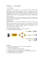
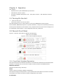
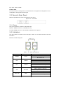
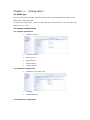
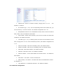
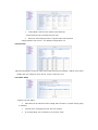
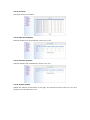
MRS4616A User Manual Contents Chapter 1 Introduction................................................................................ 3 1.1 overview.............................................................................................. 3 1.2 Physical Description........................................................................ 4 1.3 Technical Specifications.................................................................4 Chapter 2 Operation.................................................................................... 6 2.1 Turning On the Unit.........................................................................6 2.2 Device’s Front Panel........................................................................6 2.3 Device’s Rear Panel.........................................................................7 2.4 Indicators............................................................................................ 7 2.5 Turning Off the Unit........................................................................ 8 Chapter 3 Configuration........................................................................... 9 3.1 WEB Login...........................................................................................9 3.2 System configuration..................................................................... 9 Appendix A....................................................................................................... 15 Appendix B....................................................................................................... 16 Chapter 1 Introduction 1.1 overview MRS4616A Series Gateway is a channelized Ethernet gateway for interconnecting TDM and packet-based networks. The Ethernet Gateway aggregates and switches Ethernet traffic into 8 or 16 channelized E1 circuits, each supporting up to 16 VCG. Ethernet traffic over channelized E1 lines is aggregated and transferred to the packet-switched network via the unit’s Gigabit Ethernet ports. The encapsulation method support HDLC/PPP-BCP (RFC3518)/GFP-F. The unit enables service providers to supp ly high capacity Ethernet services to remote locations. The units can also transparently connect corporate LANs utilizing existing E1 or T1 lines. Applications Typically deployed at a central location, MRS46xxA Series Gateway aggregates Ethernet Data received from other devices, thus completing a full access solution from the service provider’s central site to the customer premises. The unit supports up to maximum 16VCG, allowing the connection of up to maximum 16 different customers per site. Other typical applications include: Aggregation of Ethernet traffic over TDM wireless links Network management backhauling. Features Up to 16 remote LANs over 8 or 16 E1 circuits aggregation Support 2047Bytes frames Support VLAN tagging and QinQ function Support HDLC/PPP-BCP (RFC3518)/GFP-F encapsulation Support E1 frame or un-frame application, and N*64K for framed mode Provide statistics for each E1 channel Support E1 proprietary ring protection Configure via CLI/Web/SNMP (v1/v2c/v3) Support software and firmware upgrade -48VDC/110/220VAC flexible redundant power inputs Encapsulation MRS4616A supports HDLC、PPP and GFP-F encapsulation GFP (ITU-T G.8040, G.7041/Y.1303) 1.2 Physical Description MRS4616A is a standalone or rack mountable device. LEDs, interfaces, and control connectors are located on the front panel. For additional information, refer to Chapter 2. 1.3 Technical Specifications E1 Interface Number of Ports: 16 Compliance: G.703, G.704 Data Rate: 2.048 Mbps Impedance: 120 Ω, balanced 75Ω, unbalanced (via adapter cable Line Coding: HDB3 Connector: BNC, RJ-45 Line Protection: 15 KV ESD protections 6KV/42Ω surge protection Ethernet Interface Number of Ports: Rj45: 2 SFP: 2 Type: 10/100 Mbps, auto-negotiation, full/half duplex, flow control, MDI/MDX crossover Compliance: Relevant sections of IEEE 802.3 Max Frame Size: 2047 bytes Connector: RJ-45 Electrical Cable Type: SFP Line Protection: Built-in 1.5 KV Magnetic Isolation Protection 6KV/42Ω surge protection Internal Bridge Number of VLANs: Up to 16 Compliance: Relevant sections of 802.1Qand QinQ double tagging LAN Table: Up to 2K MAC addresses (learned) Management Ports Console Port Interface standard: RS-232 Connector: RJ-45 Baud Rate: 115.2 kbps Power Input Voltage: AC: 100-240VAC,50/60Hz DC: -48VDC (36-72VDC) AD: AC/DC dual power supply universal input Power Consumption: <10 watts Environmental Limits Operating Temperature: 0 to 50°C (32 to 122˚F) Storage Temperature: -40 to 70°C (-40 to 158˚F) Humidity: 10 to 95% (non-condensing) Physical Housing: Metal Height: 43.5 mm (1.7 in) Width: 430.0 mm (16.9 in) Depth: 200.0 mm (7.9 in) Weight: 2.7 kg (5.9 lb) Standard 1U and 19-inch rack mount size Chapter 2 Operation This chapter: • Explains how to power MRS4616A up and down. • Describes the device's panel • Provides a detailed description of the front panel controls and indicators and their functions. 2.1 Turning On the Unit • To turn on the unit: Connect the power cord to the mains. The PWR indicator turns on and remains on as long as MRS4616A receives power. Once installed, MRS4616A requires no operator attention, except for occasionally monitoring the front panel indicators. Intervention is only required when the unit must be configured to its operational requirements, or when diagnostic tests are performed. 2.2 Device’s Front Panel Figure 3-1 lists the front panel of different specifications Figure 2-1 Front Panel Figure 2-1-1 E1 120Ω 2 optical 2 Ethernet Figure 2-1-2 E1 120Ω 4 Ethernet Figure 2-1-3 E1 75Ω 2 optical 2 Ethernet Figure 2-1-4 E1 75Ω 2 Ethernet 2.2.1 Front Panel Interface Description The front panel has four Ethernet interfaces or two Ethernet interfaces and two SFP optical interface, a Console port, 8/16 of the E1 (BNC or RJ45) interface and RESET button. Ethernet interface Ethernet interface using with Lamp Reset Used to restore the factory default configuration,. The system during normal operation, if you hold down the Reset button more than 3 seconds, the system will restore the factory default configuration and restart. E1 Interface Q9(75Ω),RJ45(120Ω) Console Port Provide a series of Config and CLI command device configuration management. Local configuration through the Console port 2.3 Device’s Rear Panel Different specifications of the rear panel are the same. Figure 2-2 Rear Panel 2.3.1 Power Two power interface, AC220V or DC-48V input AC220V: POWER connect ‘L’, RETURN then ‘N’; DC-48V: POWER connect to the cathode, RETURN then negative. 2.4 Indicators The unit's LEDs are located on the front panel. Table 3-1 lists the functions of the LED indicators. Ethernet indicator diagram Table Name POWER 2-1. LEDs and Controls Colors Green Functions On- Unit is powered Off- Unit is off On- Fiber connected FB2 GREEN Flash- Device transmitting data Off- Fiber disconnected On- Fiber connected FB1 GREEN Flash- Device transmitting data Off- Fiber disconnected Flash- System is working SYS YELLOW On- System is abnormal Off- System is booting abnormally LOS1~16 RED SPD1~4 GREEN On- Channel alarm detected Off- no alarm currently detected On- Ethernet Speed is 100M Off- Ethernet Speed is 10M Flash- Device is transmitting data. ACT1~4 YELLOW On- Network is established Off- Ethernet disconnected 2.5 Turning Off the Unit To turn off the unit: • Remove the power cord from the power source. Chapter 3 Configuration 3.1 WEB Login Use IE browser as an example. Open the web browser, input the default IP address in the address bar: 192.168.0.168. As below the login dialog, input the right username and password. The username and password is all “root”. 3.2 System configuration 3.2.1 System information Software Version. Firmware Version. Running Time. MAC Address. System Name. System Reboot. 3.2.2 Network configuration IP Address: 192.168.0.168. Net Mask. Default Gateway. 3.2.3 Password configuration User can change password on this page and re-login use the new password. 3.2.4 SNMP configuration Test SNMP function in this web page. 3.2.5 Global Configuration Dot1Q Vlan Enable: Vlan&QinQ function enable. ①Enable②Disable,The default configuration is Disable. Admin Vlan: User interface VLAN. The default configuration If Dot1Q Vlan Enable is set to Enable, then that becomes closed, you need this first configuration is 0 or WEB page will not be able to enter. QinQ Enable: Double Vlan enable. ①Enable②Disable QinQ Ether Type: Double Vlan type setup. E1 QinQ Pvid: Double VLAN value. Ethernet Isolation 3.2.6 Channel configuration Channel ID: Choice of channel number, ranging from 1 to 16. The default is 1 channel. E1 List Bind (eg: 1, 3-5): The corresponding channel E1 number list, you can choose any 1-16 a few road E1. The default configuration for 1-16. Encapsulation Protocol: E1 encapsulation mode, there are three modes of GFP / HDLC / PPP. The default is GFP mode. Frame Mode: Frame mode selection, there are two modes of framed and unframed. The default is framed. Time Slot (eg: 1, 3-5): In framing mode, the choice of the number of time slots, ranging from 1 to 31. Can be arbitrarily chosen, the default configuration of 1-31. GFP TX Scramble:GFP sent scrambling code, the default is Both。 GFP Rx Scramble:GFP receive scrambling code, the default is Both。 GFP LCAS:GFP LCAS enabled,the default is Enable GFP FCS:GFP frame check,the default is Disable。 GFP Ext Header:involve Null-Header and Linear-Framer,the default is Null-Header。 Vlan Mode:vlan mode,involve access/Trunk。 PVid(1-4094):Port Vlan id,Divided Vlan network identification number, the default is 1。 Loop Detection:E1 loopback detection。the default is Enable。 3.2.7 Ethernet configuration Config Mode: Set the work mode of the Ethernet ①auto②half-10③full-10④half-100⑤full-100 Ethernet rate-limiting function ①Egress Rate Limit transmit ②Ingress Rate Limit receive:The default configuration is 0. 3.2.8 E1 Test Open this web page, set the E1 Index same with self-loop port number,Pattern Text choice enable and click Config to check the E1 circuit is normal or not. 3.2.9 Vlan Table Support 16 vlan tables: Vlan table will be effective when 'Dot1Q Vlan' function in ‘System Config' page is enabling. 0 delete vlan, management vlan can’t be deleted. If corresponding vlan is deleted, pvid need be reset. 3.2.10 E1 alarm This page shows the E1 alarm. 3.2.11 Ethernet Statistics Ethernet statistics will automatically refresh every 10s. 3.2.12 Channel statistics Channel statistics will automatically refresh every 10s. 3.2.13 System update Update the software and firmware in the page, the software must be named as *.bin and firmware must be named as *.rbf. Appendix A Connector Wiring A.1 Ethernet Connector The 10/100BaseT Ethernet electrical interface is an 8-pin RJ-45 connector, wired according to Table A-1. Table A-1. 10/100BaseTX Ethernet Connector Pinouts Pin Function 1 Tx+ 2 Tx- 3 Rx+ 4, 5 - 6 Rx- 7, 8 - A.2 E1 Connector The E1 electrical interface is an 8-pin RJ-45 connector, wired according to Table A-2. Table A-2. E1 Connector Pinouts Pin Function 1 Rx+ 2 Rx- 3 NC 4 Tx+ 5 Tx- 6 NC 7 NC 8 NC A.3 Console The Console interface is an 8-pin RJ-45 connector, wired according to Table A-3. Table A-3. Console Pinouts Pin Function 3 Txd (TD) 6 Rxd (RD) 4, 5 Ground (GND) Appendix B Warranty Card Our company is committed to provide users with the following terms: 1. Warranty service 1) Within the charge free warranty term (within 12 months since the purchase of the product), damaged parts can be exchanged free of charge and maintenance charges will be free in the conditions that the device is considered to be malfunctioned in normal service by our company. 2) Within the charged warranty term (more than 12 months and within 36 months since the purchase of the product), damaged parts will be charged for corresponding cost with free maintenance service in the conditions that the device is considered to be malfunctioned in normal service by our company. 2. Users can not enjoy warranty service with the following cases and corresponding cost of damaged parts replacing and maintenance service will be charged (1) Exceed 36 months since the purchase of the product (2) Can’t provide certificate of purchasing date, and serial No. of product shows that ex-works term has exceeded 36 months; (3) Include but not limit to the abnormal service conditions such as violent knocking, extrusion, drop, liquid immersion that cause damages; (4) Fragile label on the device is damaged; (5) User disassembles this product himself (6) Force majeure that leads to product damage, such as earthquake, flooding and lightening stroke; 3. The newly installed parts after maintenance will be repaired free of charge within 12 months since the installation date. 4. When malfunction occurs, users can choose to send it to our company to receive maintenance service or to post it to maintenance points of our company all over the country to be repaired. 5. Our company does not undertake any responsibilities for losses caused by abnormal operation; for losses really caused by product itself, including but not limited to all direct or indirect losses due to data loss, our company will only undertake responsibilities within the selling price of products. Repair and Maintenance Record Product Name: MRS 4616A Maintenance date 1 2 3 4 5 Device No.: No. of Service Bill