1
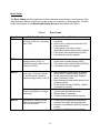
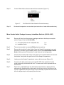
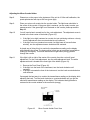
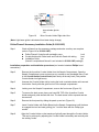
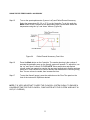
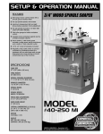
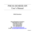
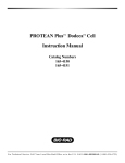
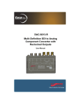
Cole-Parmer
2100/2100UV SERIES
SPECTROPHOTOMETER
USER’S MANUAL
Cole Parmer Instruments Company
625 East Bunker Court
Vernon Hills, IL 60061
800-323-4340
Table of Contents
General Information…………………………………………………………………………………….……....
3
Introduction………………………….………………………................................................................................. 4
Working Principle………………………………..………………………………………………………..….…..... 4
Specifications........................…………………..…………...………………………………………………………. 5
Unpacking Instructions………………………..……………………………………………………………..... 5
Installation………………………………………………..……………………………………………………………..... 6
2100 and 2100UV Spectrophotometer Operation Panel………………………...... 6
Model 2100UV Operation Panel……………………………………………………...........
Model 2100 Operation Panel………………….…………………………………………….
6
9
Start-up Self Calibration…………………………………………………………………………………….… 10
Changing Curette Holders……………………………………………..……….…………….………….... 13
Basic Operation…………………………………………………………………………………………………….... 14
Sample Preparation and Analysis………………………………………………………...
Concentration Mode……………………………………………………………………………..
Factor Mode…………………………………………………………………………………………...
14
15
15
Output and Data Processing……………………………………………………………………………..
16
16
16
Printer………………………………………………………………………………………………….....
Application Software……………………………………………………..…………………..
Maintenance…………………………………………………………………………………………………………..
Lamp Replacement………………………………………………………………………..…....
Wavelength Calibration Check…………………………………………………………...
Absorbance Accuracy Check……………………………………………………………..
Stray Light Check…………………………………………………………………………………...
17
17
18
19
20
2100 and 2100UV Parts List………………………………………………………………………….……..... 21
Troubleshooting………………………………………………………………….…………………….……….……. 23
Error Codes……………………………………………………………………………………………………………… 25
Attachment……………………………………………………………………………………………………………… 26
2
General Information
The spectrophotometer described in this manual is designed to be used by properly
trained personnel in a suitable equipped laboratory. For the correct and safe use of this
spectrophotometer it is essential that laboratory personnel follow generally accepted safe
procedures in addition to the safety precautions called for in this manual.
The inside of the power supply unit is a hazardous area and its cover should not be
removed under any circumstances. ANY Servicing must be done by an authorized person.
Some of the chemicals you use in the spectrophotometer may be corrosive, flammable,
radioactive, toxic, and/or potentially infective. Care should be taken to follow the normal
laboratory procedures for handling chemicals and samples. Please carefully read the
Safety, Electrical, Warning, Performance and Radio Interference instructions below.
Safety
This spectrophotometer has been designed and tested in accordance with EN 61326-1:
1997 Safety Requirements for Electrical Equipment for Measurement, Control, and
Laboratory Use standard (EMC Requirements). The spectrophotometer has been supplied
in a safe condition.
The safety statements in this manual comply with the requirements of the HEALTH AND
SAFETY AT WORK ACT, 1974.
Read the following before installing and using the instrument and its accessories.
Electrical
Before switching on the spectrophotometer, make sure it is set to the voltage of the local
power supply (see Installation).
The main plug shall be inserted in a socket provided with a protective earth contact. The
protective action must not be negated by the use of an extension cord without a protective
conductor.
Warning
Any interruption of the protective conductor inside or outside the spectrophotometer or
disconnection of the protective earth terminal is likely to make the spectrophotometer
dangerous. Intentional interruption is prohibited. Whenever it is likely that the protection
has been impaired, the spectrophotometer shall be made inoperative and be secured
against any unintended operation. NEVER touch or handle the power supply on the Model
2100UV due to the high voltage.
The protection is likely to be impaired if, for example, the apparatus
• Shows visible damage
• Fails to perform the intended measurements
• Has been subjected to prolonged storage under unfavorable conditions
3
•
Has been subjected to severe transport stresses
Performance
Carry out performance checks with particular reference to wavelength and absorbance
accuracy to ensure that the spectrophotometer is working within its specification,
especially when making measurements of an important nature. Performance checks are
detailed in this manual.
Radio Interference
For compliance with the EMC standards referred to in the EC Declaration of Conformity, it
is necessary that only shielded cables supplied by are used when connecting the
instrument to computers and accessories.
Introduction
The Model’s 2100 and 2100UV Spectrophotometers are single beam, general purpose
instruments designed to meet the needs of the conventional laboratory. 2100 and 2100UV
are ideal for various applications, such as: Clinical Chemistry, Biochemistry,
Petrochemistry, Environmental Protection, Food and Beverage Labs, Water and Waste
Water Labs and other fields of quality control.
Featuring a digital display of photometric result, easy operation and wavelength range of
325~1000 nm (Model 2100) or 200~1000 nm (Model 2100UV), 2100 and 2100UV are
ideal for measurements in the visible wavelength region of the electromagnetic spectrum
(ultraviolet and visible for the Model 2100UV).
Working Principle
The spectrophotometer consists of five parts:
1) Halogen/Deuterium Lamp to supply the light;
2) A Monochromator to isolate the wavelength of interest and eliminate the unwanted
second order radiation;
3) A Sample Compartment to accommodate the sample solution;
4) A Detector to receive and convert the transmitted light to an electrical signal;
5) A Digital Display to show absorbance or transmittance. Figure-1 illustrates the
relationship between these parts.
100%T
0A
Light Source
Monochromator
Figure-1
Sample Compartment
Detector
Digital Display
Block Diagram for the Spectrophotometer
In your spectrophotometer, light from the lamp is focused on the entrance slit of the
monochromator where the collimating mirror directs the beam onto the grating. The grating
4
disperses the light beam to produce the spectrum, a portion of which is focused on the exit
slit of the monochromator by a collimating mirror. From here the beam is passed to a
sample compartment through one of the filters, which helps to eliminate unwanted second
order radiation from the diffraction grating. Upon leaving the sample compartment, the
beam is passed to the silicon photodiode detector and causes the detector to produce an
electrical signal that is displayed on the digital display.
Specifications
Table-1 lists the specification for both Model 2100 and 2100UV.
Table-1
Specifications
Model 2100
Wavelength Range
Spectral Bandpass
Wavelength Accuracy
Wavelength Repeatability
Stray Radiant Energy
Photometric Range
Model 2100UV
325~1000 nm
200~1000 nm
5 nm
Better than 2 nm
Better than 1 nm
< 0.3% T at 340 and 400 nm
0~125%T
-0.1~2.5 Abs
0~1999 C (0~1999 Factor)
±0.004 Abs at 0.5 Abs
115/230 V. ±10%, 60/50 Hz switchable
4-poisiton Cuvette Holder
470W x 400D x 140H (mm)
10 kg (22 lbs)
12 kg (27 lbs)
Photometric Accuracy
Power Requirements
Sample Holder
Dimensions
Net Weight
Unpacking Instructions
Carefully unpack the contents and check the materials against the following packing list to
ensure that you have received everything in good condition:
Packing List
Table-2
Packing List
Quantity
Description
Spectrophotometer
Dust Cover
Cuvette
4-position Cuvette Holder (Manual)
Power Cord
User Manual
Model 2100
1
1
Set of 4, glass
Model 2100V
1
1
Set of 2, quartz; Set of 4, glass
1 (installed)
1
1
1 (installed)
1
1
5
Installation
1. After carefully unpacking the contents, check the materials with the packing list above to
ensure that you have received everything in good condition.
2. Place the instrument in a suitable location away from direct sunlight. In order to have the
best performance from your instrument, keep it as far as possible from any strong
magnetic or electrical fields or any electrical device that may generate high-frequency
fields. Set the unit up in an area that is free of dust, corrosive gases and strong vibrations.
3. Remove any obstructions or materials that could hinder the flow of air under and around
the instrument.
4. Select either 230V or 125V/115V on the voltage selector switch on the back of the 2100
and 2100UV shown in Figure-2, to match your local main voltage supply.
5. Turn on your 2100 and 2100UV and allow it to warm up for 15 minutes before taking
any readings.
Figure-2
Back of 2100 and 2100UV
2100 and 2100UV Spectrophotometer Operation Panel
Model 2100UV Operation Panel
Figure-3 shows the Model 2100UV and its Components:
• Sample Compartment: Accommodate different cuvette holders. 4-position Cuvette
Holder is preinstalled in the standard package
• Power Indicator: Indicate whether power is on or off
• Cuvette Holder Control Knob: Select the sample position of the 4-position Cuvette
Holder by pulling out or pushing in
•
Operation Panel: has eleven components, see below for details.
6
Figure-4 illustrated the detailed information of the Operation Panel:
1. Data Display Screen: Display the data of Transmittance, Absorbance, Concentration, and
Factor modes.
2. Mode Indicator: The red LED light indicates the operation MODE. Allow the operator to
know the measurement mode currently in use (T--%Transmittance, A--Absorbance, C-Concentration, and F--Factor).
3. 0A/100%T Button: Blank the 2100/2100UV when blank reference solution is in the Sample
Compartment. Every time a new wavelength is selected, press 0A/100%T Button to
confirm. It will automatically blank the 2100/2100UV.
4. MODE Button: There are four modes. T mode is transmittance mode; A mode is
absorbance mode; C mode is to measure unknown sample concentration through a
standard solution; F mode is to measure unknown value with a previously determined
factor.
5. PRINT Button: Press to send Data Display Screen and Wavelength Display Screen
results to RS-232C port and printer.
6. Wavelength Display Screen: Display the current/desired wavelength.
7. Wavelength Control Buttons: Allow user to select the desired wavelength with the ∧ and
∨ (increase and decrease) buttons.
8. INC/DEC (Concentration/Factor Buttons) and Lamp Control Buttons: Allow user to
increase or decrease the displayed Concentration at C mode or Factor number at F mode.
At T mode or A mode, press INC button will shutdown the halogen lamp (W), press DEC
mode will shutdown the deuterium lamp (D2). To turn on the lamps, just press the
INC/DEC button again.
9. ENT Button: First press at C mode enters reading on Data Display Screen. Other
presses send displayed results to printer. If using Windows-based Application Software,
press this button to communicate with the software (refer to the 2100 Series
Spectrophotometer Software User’s Manual Version SB-2.10 for details). If operating in
F Mode, then press to enter factor. This causes the Mode to enter the factor number and
change to C mode.
10. Visible Lamp Indicator (W): In the operating mode of Absorbance or %Transmittance (A
or T), pressing the INC button will turn off/on the lamp.
11. UV Lamp Indicator (D2): In the operating mode of Absorbance or %Transmittance (A or
T), pressing the DEC button will turn off/on the lamp. Since Deuterium lamp (D2) is an
expensive item, it is recommended to turn off the) when not using ultraviolet light for
measurement.
7
Figure-3
Model 2100UV Spectrophotometer
Figure-4
Operation Panel of Model 2100UV
8
Model 2100 Operation Panel
The Model 2100 has the similar outlook as Model 2100UV. It also has the following
components:
• Sample Compartment: Accommodate different cuvette holders. 4-position Cuvette
Holder is preinstalled in the standard package
• Power Indicator: Indicate whether power is on or off
• Cuvette Holder Control Knob: Select the sample position of the 4-position Cuvette
Holder by pulling out or pushing in
•
Operation Panel: has nine components, see below for details.
Figure-5 illustrated the detailed information of the Operation Panel:
1. Data Display Screen: Display the data of Transmittance, Absorbance, Concentration, and
Factor modes.
2. Mode Indicator: The red LED light indicates the operation MODE. Allow the operator to
know the measurement mode currently in use (T--%Transmittance, A--Absorbance, C-Concentration, and F--Factor).
3. 0A/100%T Button: Blank the 2100/2100UV when blank reference solution is in the Sample
Compartment. Every time a new wavelength is selected, press 0A/100%T Button to
confirm. It will automatically blank the 2100/2100UV.
4. MODE Button: There are four modes. T mode is transmittance mode; A mode is
absorbance mode; C mode is to measure unknown sample concentration through a
standard solution; F mode is to measure unknown value with a previously determined
factor.
5. PRINT Button: Press to send Data Display Screen and Wavelength Display Screen
results to RS-232C port and printer.
6. Wavelength Display Screen: Display the current/desired wavelength.
7. Wavelength Control Buttons: Allow user to select the desired wavelength with the ∧
and ∨ (increase and decrease) buttons.
8. INC/DEC (Concentration/Factor Buttons): Allow user to increase or decrease the
displayed Concentration at C mode or Factor number at F mode.
9. ENT Button: First press at C mode enters reading on Data Display Screen. Other
presses send displayed results to printer. If using Windows-based Application Software,
press this button to communicate with the software (refer to the 2100 Series
Spectrophotometer Software User’s Manual Version SB-2.10 for details). If operating in
F Mode, then press to enter factor. This causes the Mode to enter the factor number and
change to C mode.
9
Figure-5
Operation Panel of Model 2100
Start-up Self-Calibration
The Model 2100 and 2100UV have self-calibration programs that begin when the
instrument is powered on. The following are the steps taken automatically each time the
instrument is switched on. Each step is displayed on the Wavelength Display Screen.
Figure-6 to Figure 12 and Table-3 show the detailed information of the Start-up SelfCalibration: P1 Process, P2 Process, P3 Process, P4 Process, Show Process, PC CONN
Process, and Normal Start-up Screen.
Figure-6
P 1 Process
10
Table-3
Start-up Self-Calibration
Display
P1
2100
Check the electronic components and
positions secondary filters
P2
P3
Monochromator locates starting position
Monochromator locate “0” order light
and measure initial light energy
• Monochromator go to 546 nm
• Instrument sets 0%T
• Initiates RS-232C port. Show
“PC-CONN”
• Set 100%T (blank reference)
P4
2100UV
Check electronic components, initiates
lamp selection and positions secondary
filters
Monochromator locates starting position
Monochromator locate “0” order light, and
measure initial light energy
• Monochromator goes to 546 nm
• Instrument sets 0%T.
• Initiates RS-232C port. Show
“PC-CONN”
• Set 100%T (blank reference)
Figure-7
P 2 Process
Figure-8
P 3 Process
11
Figure-9
Figure-10
Figure-11
Figure-12
P 4 Process
Show Process
PC CONN Process
Normal Start-up Screen
12
Changing Cuvette Holders
There are seven different Cuvette Holders (Sample Holders) (refer to Figure-13 and
Figure-14, from left to right):
• S2100-101P: Test Tube Holder for 8~25 mm diameter test tubes. Includes Universal
Base, one holder, and Top Hat for up to 150 mm tall test tubes
• S2100-102P: Rectangular Long Path Cell Package for cells up to 100 mm pathlength.
Includes Universal Base and one holder
• S2100-103P: Single 10 mm Cuvette Holder Package. Includes Universal Base and one
holder
• S2100-104P: Cylindrical Cuvette Holder Package for cells up to 100 mm pathlength.
(22 mm diameter). Includes Universal Base and one holder
• S2100-105P: Water-Jacketed Single Cuvette Holder Package for 10 mm cuvettes for
temperatures from 0~95°C. Includes Holder, Universal Base, and Flowthru Panel (Water Bath Required)
• S2100-106P: Micro-Cuvette Holder Package for use with 10 mm microcuvettes.
Includes adjustable x-y base and holder
• S2100-109P: Peltier Flowcell Package for 15°C to 40°C. Includes p/n S2100-109,
peristaltic temperature/pump/flow-thru controller, p/n S2100-107A, Peltier
Thermal Electric Cuvette Holder and Peltier/Flow-thru
Refer to the Attachment in this Manual for the detailed Installation Guide. The only tool
needed is a standard Philips head screwdriver.
Figure-13
Figure-14
Cuvette Holder S2100-101P to S2100-104P
Cuvette Holder S2100-105P, 106P and 109P
13
Basic Operation
Three Basic Operations: Sample Preparation and Analysis, Concentration Mode--C,
and Factor Mode are shown in this section.
Sample Preparation and Analysis
A.
1.
Spectrophotometer Warm-up and %T Check
Turn on the spectrophotometer by turning on the Power Switch (IO). Allow 15
minutes for the instrument to warm up.
Operational Note: The instrument performs four self-calibration checks every time the
power is turned on. For details of the self-calibration and the error codes associated with
this, please see the Error Codes section of this manual.
2.
3.
B.
4.
5.
6.
7.
C.
8.
9.
10.
Select either the T (Transmittance Mode) or A (Absorbance Mode) by pressing the
MODE button until the red light for T or A is on.
Select the desired wavelength by pressing the appropriate Wavelength Control
buttons ∧ and ∨. At any time if the wavelength is changed, the Data Display
Screen will display “BLA”. This serves as a reminder that a reference is necessary
with the change of the wavelength and you need to push 0A/100%T Button to blank.
Sample Preparation
Make a blank reference solution by filling a clean cuvette (or test tube) half full with
distilled or de-ionized water or other specified solvent. Wipe the cuvette with tissue
to remove the fingerprints and droplets of liquid.
Insert the blank cuvette into one cell of the 4-position Cuvette Holder. Push or pull the
Cuvette Holder Control Knob so that the cuvette is in the light path). Close the cover.
Set 0.000A or 100%T with the 0A/100%T Button.
Remove the blank cuvette if you are testing more than three samples. Set it aside in
the case that you may need to adjust the 0A/100%T button later (i.e. change the
wavelength).
Sample Analysis
Rinse a second cuvette with a small amount of the sample solution to be tested. Fill
the cuvette half full and wipe it.
Put the sample cuvette in the Sample Compartment. Close the cover.
Read the T or A from the Data Display Screen. If you are reading more than one
cuvette, be sure to carefully move the stage to the next position by pulling on the Cuvette
Holder Control Knob until you feel the holder “click” into place. Be sure to make note of
the test results (or print) for each sample. Remove the sample cuvette(s).
11.
12.
If you are to test the same sample at other wavelengths, repeat step 3 to 10 for
each wavelength.
For each new sample you analyze, repeat step 2 to 11.
14
Concentration Mode
C is used for determining the concentration of unknown samples.
NOTE: This method should only be used when the relationship between Absorbance and
Concentration is known to be linear. The concentration of the Standard solution used to
calibrate the instrument should be higher than the most concentrated sample.
1. Select the desired wavelength by pressing Wavelength Control buttons ∧ and
∨turning the wavelength control knob.
2. Using the MODE button, select A mode.
3. Insert the cuvette containing the blank solution.
4. Set 0.000A with the 0A/100%T button.
5. Using the MODE button, select C mode.
6. Insert a cuvette containing a standard solution of known concentration in the first
position of the Sample Compartment and set the Data Display Screen to be the value
of the standard by using the INC and DEC buttons.
7. Press the ENT button.
NOTE: If the reading changes, the factor required is too high (i.e. >1999) to be displayed.
In this case, divide the concentration by 10; re-select the C mode by successive presses
on the MODE button, cycling through the F, T, and A modes, and follow step 2 above to
set the concentration of the standard to the reduced value.
8. With the standard concentration set, determine the concentration values of samples
with unknown concentration by inserting the sample cuvette into the Sample
Compartment and reading the value direct from the Data Display Screen.
9. To read the value of the multiplier used to convert Abs to Concentration, after
measuring all the samples, change the mode to F and read the multiplier from Data
Display Screen. Keep a record of this value for future use.
Operational Note: if the mode switch is changed to read F or A, the Concentration C
reading is “frozen”, and cannot be changed. This requires the operator to re-start at step 1.
Factor Mode
This is a special mode for measuring concentration values of unknown samples using a
previously determined factor to convert absorbance readings to concentration.
1.
2.
3.
4.
After setting the wavelength, and setting zero Abs on the blank solution, using the
MODE button, select F mode.
Insert a cuvette containing a sample.
Using the INC and DEC buttons, set the Data Display Screen to the desired value
of the multiplier.
Press the ENT button. The spectrophotometer switches to the C mode.
Operational Note: If the Concentration of the sample is too high to be displayed, the
instrument will not switch to C mode when the ENT button is pressed. Dilute the sample
and multiply the concentration reading by the dilution factor to obtain the original sample
15
concentration. If dilution is impossible or causes other problems, you may divide the factor
value by “10” or “100” and follow Step 1 to 4 to enter the “new” factor value. You need to
calculate the sample concentration by multiplying readout with the multiple “10” or “100”.
5.
6.
Read the concentration value of the sample direct from Data Display Screen.
Insert a cuvette containing the next sample and read the result. Repeat until all
samples have been measured.
Operational Note: If the MODE switch is changed to A or T, then the concentration
reading is “frozen”. This requires the operator to re-start at step 1.
Output and Data Processing
Printer
Model 2100 and 2100UV have a RS232C Interface connector that can be connected to
any RS232 printers (provides RS232 printer, p/n: S1100-206, as an optional accessory). It
requires a 9-pin, null modem connection cable. The RS232 Printer Setting should be as
follows:
• Baud Rate: 9600bps
• Parity: None
• Data Bits: 8
• Stop Bit: 1
Application Software
The Application Software--2100 is Windows-based software designed to operate with
Spectrophotometer Model 2100 and 2100UV. Model 2100 and 2100UV uses its RS232C
Interface connector to connect with a PC. The software runs on a PC with Windows®
95/98/Me/NT/2000/XP operating system installed. The Software offers two additional
analytical methods: Standard Curve and Absorbance vs. Time Kinetics. It performs the
following methods for analysis:
• Absorbance/%Transmittance/Concentration: measure the Absorbance,
%Transmittance, Concentration/Standard, or Concentration/Factor at a single
wavelength within the range of 325~1000 nm (200~1000 nm for 2100UV).
• Standard Curve: create a calibration curve (choice of 4 curve fits) with up to 8
standard solutions at a single wavelength to determine concentrations of unknown
samples.
Absorbance vs. Time Kinetics: measure a sample’s absorbance change over a
selected period of time, store the test results in data table, and display the results
graphically.
Refer to the 2100 Series Spectrophotometer Software User’s Manual Version SB-2.10
for detail.
16
Maintenance
Lamp Replacement
A.
Replace Tungsten-Halogen Lamp
1. Turn off and unplug the instrument.
2. Remove the four screws on the sides of the spectrophotometer.
3. Remove the Cuvette Holder Control Knob by unscrewing the rod counterclockwise.
4. Remove the cover of the instrument very carefully and place it in front of the instrument.
HINT: Lift up about 3~4 inches, and once the instrument has cleared the backside grill
plate, lift the back of the cover up towards the front. The front of the instrument will act as a
“hinge”. BE SURE TO NOT PULL PANEL WIRING LOOSE!
5. Unplug and remove the lamp from ceramic base (the white connector). Insert the new
lamp; pushing it in as far as it will go.
Part Number: S2100-515 (6V 10W G4 type)
CAUTION: DO NOT HANDLE THE LAMP WITH BARE FINGERS. USE TISSUE OR
CLOTH WHEN HANDLING LAMP.
6. Turn on the instrument. Set the wavelength at 340 nm, insert an empty cuvette, and
blank the instrument. If the energy is low, adjust the lamp by “pulling” or “pushing” it so
that the light beam is focused on the entrance slot of the monochromator. Since the
lamp socket is pre-aligned, there will be minimum, if any, adjustment required.
7. Reinstall the instrument cover by positioning the front of the cover first and then sliding
the back of the cover over the backside grill plate. Be sure all wires from the front panel
are not pinched in the process.
Note: The latest version of Model 2100/2100UV has a lamp access door at the back of the
instrument. If your Model 2100/2100UV has the lamp access door, you do not need to
open the cover. Just open this door to replace the lamp.
8. Reinstall the four screws and the Cuvette Holder Control Knob.
B.
Replace Deuterium Lamp
WARINING: Wear UV protection Glasses before changing the Deuterium Lamp!
1. Turn off and unplug the instrument (VERY IMPORTANT: HIGH VOLTAGE).
2. Remove the four screws on the sides of the spectrophotometer.
3. Remove the Cuvette Holder Control Knob by unscrewing the rod counterclockwise.
4. Remove the cover of the instrument very carefully and place it in front of the instrument.
HINT: Lift up about 3~4 inches, and once the instrument has cleared the backside grill
plate, lift the back of the cover up towards the front. The front of the instrument will act as a
“hinge”. BE SURE TO NOT PULL PANEL WIRING LOOSE!
17
5. Remove the metal plate covering the Deuterium lamp by removing the two screws
from the rear of the plate (make a note of the wire color and their matching connectors).
6. Remove the lamp by disconnecting the 3-wire connector and pulling straight up on the
lamp socket. DO NOT PULL on the lamp itself. This may cause the lamp to break.
7. Replace the pre-aligned lamp with a lamp provided by or an authorized Service
Provider (Call 1-800-588-9776 for details). This comes pre-assembled with lamp socket.
8. Reconnect the wire connector and be sure the lamp and lamp socket is securely in
place (make sure the wire connection orientation is the same as step 5.)
9. Turn on the instrument. After the Start-up Self Calibration, select 300 nm and press
0A/100%T Button. Check to make sure that the light beam is focused on the entrance slit
of the monochromator. If it is not, adjust the mounting screws on the Deuterium lamp
holder to align the lamp.
Note: The latest version of Model 2100/2100UV has a lamp access door at the top of the
instrument. If your Model 2100/2100UV has the lamp access door, you do not need to
open the cover. Just open this door to replace the lamp.
CAUTION: THE LAMP MAY BE HOT! TAKE PRECAUTIONS TO PREVENT POSSIBLE
BURNS.
Wavelength Calibration Check
Normally the 2100 Series spectrophotometer retains its wavelength calibration indefinitely.
However if the instrument receives a severe shock or is abused, use the following methods
to check wavelength calibration. Please note that this test requires the Didymium filter, p/n
S2100-116, or the Holmium Oxide filter, p/n S2100-115.
In the filter method, the didymium filter has two distinct absorbance peaks at 529 nm and
807 nm. The Holmium filter has a distinct peak at 361 nm. When the instrument is
calibrated properly you will find minimum Transmittance (maximum Absorbance) at the
range ± 2 nm from these peaks. Note that the specific Transmittance values are not
important as you are only looking for the wavelength where the minimum Transmittance
(maximum Absorbance) occurs.
Note: If you calibration filter has a certified peak/valley curve attached, please use the
peaks on the curve to verify the instrument.
Holmium Oxide Filter Method
1. Turn instrument on and allow it to warm up for 15 minutes.
2. Select the A mode.
3. Set the wavelength to 350 nm.
4. Make sure the cuvette holder is empty and place it in the Sample Compartment. Close
the lid.
5. Set zero Absorbance by pressing the 0A/100%T button. Wait a few seconds while the
display flashes ‘BLA--’. The reading on the Data Display Screen should be 0.000A. If
not, repeat step 5.
6. Remove the cuvette holder and insert the Holmium filter into it. Place it in the Sample
Compartment and close the lid.
18
7. Record the Absorbance reading on the Data Display Screen.
8. Advance the wavelength setting by 1 nm and repeat step 4 to 7.
9. Repeat step 8 until the wavelength setting reaches 370 nm.
10. Look for the maximum absorbance reading obtained, and this should be found between
359 and 363 nm. The wavelength accuracy of the 2100 is ± 2 nm.
Didymium Filter Method
1. Set the Wavelength to 800 nm.
2. Make sure the cuvette holder is empty and place it in the Sample Compartment. Close
the lid.
3. Set zero Abs by pressing the 0A/100%T button. Wait a few seconds while the display
flashes ‘BLA--’. The Data Display Screen should then be 0.000A. If not, repeat step 3.
4. Remove the cuvette holder and insert the Didymium filter into it. Place it in the Sample
Compartment and close the lid.
5. Record the Absorbance reading on the Data Display Screen.
6. Advance the wavelength setting by 1nm and repeat step 2 to 5.
7. Repeat step 6 until the wavelength setting reaches 815 nm.
8. Look for the maximum absorbance reading obtained, and this should be found between
805 and 809 nm. The wavelength accuracy of the 2100 is ± 2 nm.
9. If a “middle” wavelength check is desired, set the wavelength to 522 nm (optional)
10. Make sure the cuvette holder is empty and place it in the Sample Compartment. Close
the lid.
11. Set zero Abs by pressing the 0A/100%T button. Wait a few seconds while the display
flashes ‘BLA’. The reading should then be 0.000A. If not repeat step 11.
12. Remove the cuvette holder and insert the Didymium filter into it. Place it in the Sample
Compartment and close the lid.
13. Record the absorbance reading on the Data Display Screen.
14. Advance the wavelength setting by 1nm and repeat step 10 to 13.
15. Repeat step 14 until the wavelength setting reaches 536 nm. Again, look for the
maximum absorbance reading. It should be between 527 and 531 nm.
Absorbance Accuracy Check
Specification: ± 0.5% at 1A, ± 1% at 2A.
The absorbance accuracy should be checked against a set of neutral density filters
accurately calibrated to the NIST standards. Contact your representative for more
information (1-800-588-9776).
An alternative method using potassium dichromate is described below. Due to the many
factors that might affect the results (i.e. temperature, bandpass, weighing and diluting
errors), this method is less accurate and should only be used as a guide.
Reference: Johnson E A
Potassium Dichromate as an absorbance standard
PSG Bulletin 1967, No. 17, page 505
1.
Make up N/100 sulfuric acid as the solvent and use part of it to make a solution
19
2.
3.
4.
5.
6.
7.
8.
9.
containing 120 + 0.5 mg/liter of potassium dichromate.
Wash out a square cuvette with solvent, and fill with solvent.
Put the cuvette in the adapter into the Sample Compartment and close the lid.
Set the wavelength to 350 nm.
Set the MODE button to A.
Set the reading on the Data Display Screen to 0.000A using the 0A/100%T button.
Empty the cuvette. Wash out with dichromate solution, and fill with dichromate
solution.
Put the cuvette in the adapter into the Sample Compartment and close the lid.
Read the absorbance of the standard from the Data Display Screen. The value
should be 1.288 ± 0.02 A. Refer to the notes above when interpreting the result.
Stray Light Check
Specification: Less than 0.3%T at 340 nm by ASTM E 387
A good indication as to whether the stray light level is within specification may be obtained
as follows:
1.
Set the wavelength to 340 nm.
2.
Set the MODE button to T.
3.
With the Sample Compartment empty, close the lid and press the 0A/100%T button
to set the display to 100.0%.
4.
Hold the MODE key for at least 5 s. This will set the 0.00%T. This may take a few
minutes.
5.
Prepare a solution containing 50 gm/L of sodium nitrite (NaNO2) in distilled water
and fill a square cuvette with this solution.
6.
Insert the cuvette into the Sample Compartment, and close the lid. The Data
Display Screen display should read < 0.3%T. If the reading obtained in step 4 is
greater than 0.00, it should be subtracted from the displayed Data Display Screen
to give the correct reading for the stray light value.
20
2100 and 2100UV Parts List
Table-4
2100 an d 2100UV Parts List
Catalog #
S-2100
S-2100-E
S-2100UV
S-2100UV-E
Software
S-2100-401
Accessories
S-2100-101P
S-2100-102P
S-2100-103P
S-2100-104P
S-2100-105P
S-2100-106P
S-2100-107P
S-2100-108P
S-2100-109P
S-2100-101
S-2100-102
S-2100-103
S-2100-104
S-2100-105
S-2100-107A
S-2100-107B
S-2100-108A
S-2100-109
Description
Model 2100 Spectrophotometer 5 nm Bandpass
Wavelength range: 325~1000 nm, automatic wavelength change, Voltage preset at 110V
Complete with 4-position Cuvette Holder, 4 matched Optical Glass Cuvettes
RS-232C Port, Dust Cover, User Manual
Same as Model 2100 but preset at 220 V
Model 2100UV Spectrophotometer 5 nm Bandpass
Wavelength range: 200~1000 nm, automatic wavelength change, Voltage preset at 110V
Complete with 4-position Cuvette Holder, 4 matched Optical Glass Cuvettes, 2 Quartz Cuvettes
RS-232C Port, Dust Cover, User Manual
Same as Model 2100UV but preset at 220 V
Application Software for PC's, Window's 95®/98® or above Required. Programs include Standard
Curve, Abs. /%T/Conc., and Abs.vs.Time. Includes S-2100-226 serial cable
Test Tube Holder Package for 8 to 20 mm diameter test tubes. Includes Universal Base, one
holder, and Top Hat for up to 150 mm tall test tubes
Rectangular Long Path Cuvette Holder Package for cells up to 100 mm pathlength. Includes
Universal Base and one holder
Single 10 mm Cuvette Holder Package. Includes Universal Base & one holder
Cylindrical Cuvette Holder Package for cells up to 100 mm pathlength. (22 mm diameter).
Includes Universal Base and one holder
Water-Jacketed Single Cuvette Holder Package for 10 mm cuvettes for Temperatures from
0~95°C. Includes Holder, Universal Base, and Flow-thru Panel (Water Bath Required)
Micro-Cuvette Holder Package for use with 10 mm microcuvettes. Includes adjustable x-y base
and single Cuvette Holder for 10 mm square cuvette
Peltier Package for continuous temperature control from 15 to 40°C. Includes p/n S-2100-107A,
peltier thermal electric 10 mm Cuvette Holder and p/n S-2100-107B peltier controller unit
Flow-thru Package for continuous temperature control from 15 to 40°C. Includes p/n S-2100-109
Flow-thru controller and p/n S-2100-108B flow-thru panel (requires flowcell and tubing)
Peltier/Zipper Package for flow through and continuous temperature control from 15 to 40°C.
Includes p/n S-2100-109, peristaltic/flow-thru controller and p/n S-2100-107A, Peltier Cuvette
Holder with panel (requires flowcell and tubing)
Test Tube Holder without base (Requires Universal Base)
Rectangular Long Path Cuvette Holder without base (requires universal base)
Single 10 mm Cuvette Holder without base (requires universal base)
Cylindrical Cuvette Holder without base (Requires Universal Base)
Water-Jacketed Single Cuvette Holder with flow-thru panel but without base (Requires Universal
Base, Water Bath)
Peltier Thermal Electric 10 mm Cuvette Holder with panel
Peltier controller unit for controlling temperature from 15 to 40°C
Flow-thru panel for use with ambient flowcell system (requires flowcell, tubing and p/n S-2100109 flow-thru/peltier controller
Peristaltic Pump, Peltier Thermal Temperature, and Flow-thru Controller Only
21
2100 and 2100UV Parts List continued
Catalog #
Accessories
S-2100-111
S-2100-112
S-2100-113
S-2100-114
S-2100-115
S-2100-116
S-2100-120
S-2100-121
Description
Manual 4-position Cuvette Holder (included with 2100 and 2100UV)
Universal Base. Accommodates up to 2 same or different type of holders
Top Hat for test tubes with height of 75~150 mm
Spacers for 5 mm Cuvettes
Holmium Oxide Filter
Didymium Filter
°
Haake Model DC10-B3 water bath for temperatures from 25~100 C. For use with S-2100105
°
Haake Model DC10-K10 water bath for temperature ranges of -10~100 C. For use with S2100-105
Output Device
S-1100-206
Printer (requires S-1100-207 printer cable)
S-1100-207
Printer Cable (Male 25-pin to Female 9-pin, Null Modem)
S-2100-226
RS-232C Cable (9-pin to 9-pin Female/Female, Null Modem)
Glassware
S-90-301
S-90-302P100
S-90-302P500
S-90-305P
S-90-304G
S-90-309Q
S-90-308-50G
S-90-326G
S-90-344FG
S-90-346FQ
S-90-350G
S-90-351Q
S-90-352Q
S-90-353G
S-90-354Q
S-90-355Q
S-90-358Q
S-90-359Q
Test Tube Cuvettes, 10 mm Diameter, 12 pcs
Disposable Cuvettes, Polystyrene, 10 mm Pathlength, 100 pcs
Disposable Cuvettes, Polystyrene, 10 mm Pathlength, 500 pcs
Semi-micro Disposable Cuvettes, Polystyrene, 4 mm window, 500 pcs
Square Cuvettes, Optical Glass, Set of Two
Square Cuvettes, Quartz, 10 mm, Set of Two
Cylindrical cell, 50 mm pathlength
Rectangular cell, Optical glass, 50 mm pathlength, with stopper
Flowcell, Optical glass, 4x12 mm window, 0.48 ml
Flowcell, Quartz, 4x12 mm window, 0.48 ml
Square cuvettes, optical Glass, 4 mm width 1.0 ml
Square cuvettes, Quartz, 4 mm width, 1.0 ml
Square cuvettes, Quartz, 4 mm width, with stopper, 0.5ml
Square cuvettes, Optical glass, 2 mm width, 0.5 ml
Square cuvettes, Quartz, 2 mm width, 0.5 ml
Square cuvettes, Quartz, 2 mm width, with stopper, 0.5 ml
Square cuvettes, Quartz, 2x5 mm window, 0.100 ml
Square cuvettes, Quartz, 2x2.5 mm window, 0.0 50 ml
Misc. and Replacement Items
S-1100-508
S-2100-510
S-2100-511
S-2100-515
S-2100-525
S-2100-535
Printer Paper, Package of 3
User Manual
Dust Cover
Tungsten-Halogen lamp for 2100 and 2100UV, Package of 2 (6V 10W G4 type)
Deuterium lamp for 2100UV
Fuse, 3A, quantity 1 (size 5 x 20)
22
Troubleshooting
Table-5
Troubleshooting
PROBLEM
Possible Cause
Power cord not connected to outlet
Instrument
Inoperative
Dead Power outlet
(Power
Wrong voltage setting
indicator has no Internal fuse blown or defective
light)
electronic component
No cuvette in the Sample Compartment
Instrument
cannot set
100%T (0.000A)
Check sample holder
Lamp is old or defective
Lamp is off alignment
Replace lamp
Refer to lamp replacement
instructions in this manual
Call an authorized service
engineer
Remove cuvette holder or
test tube
May be stuck open Close
shutter
Sample holder
Sample holder shutter
Defective electronic component
Incorrect
Transmittance
to Absorbance
correlation
Digital Display
does not
change
regardless of
sample
concentration
Call an authorized service
engineer
Cuvette adapter must be in
Sample Compartment to
open sample holder shutter
Light beam blocked:
• Holder misaligned
• Shutter
Defective electronic component
%T cannot be
set to 00.0%T
Solution
Plug instrument in
Change to a different outlet
Call an authorized service
engineer
Bubbles or particles in solution
Check sample preparation
and analytical procedure
Defective electronic component
Call an authorized service
engineer
Concentration reading “frozen”
MODE switch has been
changed from C to F, T or A
and back to C Restart
measurement procedure
Wrong wavelength setting
Check sample procedure
and wavelength setting
Insufficient sample volume
Fill cuvette with more
samples
Stray sample preparation vapors
Prepare the sample away
from the instrument. Use
proper ventilation
Bubbles or particles in solution
Check sample preparation
and analytical procedure
Defective electronic component or loose Call an authorized service
wiring.
engineer
23
PROBLEM
Instrument drift
and noise
Possible Cause
No sufficient warm up time
Significant temperature change
Lamp not adjusted properly
Lamp old or defective
Incorrect
readings
obtained
Solution
Check lamp has been
properly installed or has
moved during transit
Refer to lamp replacement
instructions in this manual
Replace with a new lamp
Sample Holder Misaligned
Refer to lamp replacement
instructions in this manual
Unstable power supply
Defective or dirty detector or defective
electronic component
Insufficient sample volume
Call an authorized service
engineer
Wrong wavelength setting
Failed to blank (0A/100%T)
Failed to set 0%T
Stray sample preparation vapors
Bubbles or particles in solution
Instrument out of electronic calibration
24
Fill cuvette with more
samples
Check analytical procedure
and wavelength setting
Check wavelength accuracy
according to procedure in
this manual
Prepare sample away from
instrument. Use proper
ventilation
Check sample preparation
and analytical procedure
Call an authorized service
engineer
Error Codes
The Error Codes are the classification for errors detected automatically by the instrument. Each
code represents different errors that occur during the self-calibration or during operation. The Error
Codes are displayed on the Wavelength Display Screen and are defined as Table-5.
Table-6
Error Code
ERR 01
Error Codes
Definition/Function
Causes/Solutions
Instrument unable to initialize
the lamp (2100UV) or secondary
filter (2100)
•
•
•
•
•
ERR 02
ERR 03
Monochromator unable to locate
starting position (2100); or
initialize secondary filter will not
initialize (2100UV)
•
Instrument unable to locate “0”
order light ( 2100 and 2100UV);
or monochromator unable to
locate starting position (2100UV)
•
•
•
•
•
•
ERR 04
Tungsten-halogen or deuterium
lamp is misaligned or no longer
functioning
•
Instrument is unable to locate
546nm and automatically set
0%T and 0A/100%T
•
•
•
•
•
25
Check power supply to see if proper voltage
is selected
Open cover to instrument and check CPU
board connections
Lamp-change-over motor or lamp
initialization switch malfunctioning (2100UV)
Filter-driven motor malfunctioning (2100)
Call authorized service engineer
Monochromator contact switch or gratingdriven motor is malfunctioning (2100)
Filter-driven motor malfunctioning (2100UV)
Call authorized service engineer
Monochromator contact switch or gratingdriven motor is malfunctioning (2100UV)
Check tungsten-halogen lamp. Replace
lamp if necessary (both)
Monochromator contact switch loose or mispositioning (both)
Check deuterium lamp (2100UV)—WEAR
UV-protective eyewear
Check lamps by opening cover as instructed
in this manual (See Maintenance)
Replace lamps if necessary
Contact an authorized service engineer
Check sample compartment and remove
cuvette or any object blocking light path
Place the 4-cell sample holder in the proper
position
Contact an authorized service engineer
Attachment
Refer the following attachments for the Accessory Installation Guide:
•
•
•
•
Universal Holder and Accessory Installation Guide (2100-101P to 2100-104P)
Water-Jacketed Single Cuvette Accessory Installation Guide (2100-105P)
Micro-Cuvette Holder Package Accessory Installation Guide (2100-106P)
Peltier/Flowcell Accessory Installation Guide (2100-109P)
Universal Holder and Accessory Installation Guide (S-2100-101P to S-2100-104P)
Step 1
Remove all items from the accessory package and make sure that they are
complete (refer to Figure-13 for the S-2100-101P to S-2100-104P):
z A Universal Platform
1 pc
z The specified holder
1 pc
z Installation Guide
1 pc
Step 2
The only tool needed is a standard Philips head screwdriver.
Step 3
Remove the 4-position Cuvette Holder: Open the Sample Compartment cover and
remove any cuvettes or any breakable items. Push in the Cuvette Holder Control
Knob (black knob) all the way back (First position is into the light beam).
Step 4
Unscrew the Cuvette Holder rod by turning the knob counterclockwise until removed
from holder. Gently slide the guide rod out of the Sample Compartment.
Step 5
Looking over the Sample Compartment, remove the front screw (Figure-15).
Figure-15
Remove Front Screw
Step 6
To remove the back screw, place your hand ON TOP of the 4-position Cuvette
Holder and gently slide towards the front. The back screw is then exposed and can
be removed.
Step 7
Insert Universal Holder by repeating Step 4 to 6 in reverses.
Step 8
Screw in your holder to any of the open four positions on the holder.
NOTE: If a second holder is purchased (i.e. to make into a 2-position Cuvette Holder), place the second
holder in a position so one position is skipped. For example, if the first holder is in position one,
26
and then the second must be in either position 3 or 4 of the Universal Holder.
(Two same type or different types of holders can be installed on the universal platform).
Water-Jacketed Single Cuvette Accessory Installation Guide (S-2100-105P)
Step 1
Remove all items from the accessory package made sure that they are complete
(refer to Figure-14 for S-2100-105P):
z
z
z
z
Universal Platform
Water-Jacketed Holder
Flow-thru Panel
Installation Guide
1 pc
1 pc
1 pc
1 pc
Step 2
The only tool needed is a standard Philips head screwdriver.
Step 3
Remove the 4-position Cuvette Holder: Open the Sample Compartment cover and
remove any cuvettes or any breakable items. Push-in the Cuvette Holder Control
Knob (black knob) all the way back (First position Cuvette Holder is into the light
path).
Step 4
Unscrew the Cuvette Holder rod by turning the knob counterclockwise until removed
from holder. Gently slide the guide rod out of the Sample Compartment.
Step 5
Looking over the Sample Compartment, remove the front screw (Figure-15).
Step 6
To remove the back screw, place your hand ON TOP of the 4-position Cuvette
Holder and gently slide towards the front. The back screw is then exposed and can
be removed.
Step 7
Insert Universal Holder by repeating Step 4 to 6 in reverses.
Step 8
Screw in the Water-Jacketed Holder to the first (front) position of the Universal
Holder (platform). This is to prevent stretching the tubing.
Step 9
Remove the front panel by sliding the panel up and out (Figure-16).
Figure-16
Step 10
Removable Front Panel Front View
Insert Front Panel for Water-Jacketed Cuvette in place of removed panel.
27
Step 11
Connect Water bath to the front panel tubing connectors (Figure-17).
Figure-17
Step 12
Front Panel for Water-Jacketed Cuvette Accessory
Set desired temperature on water bath (see instructions of water bath manufacturer).
Micro-Cuvette Holder Package Accessory Installation Guide for (S-2100-106P)
Step 1
Remove all items from the accessory package made sure that they are complete
(refer to Figure-14 for the S-2100-106P):
z
z
A Cuvette Holder with X-Y adjustable bas
Installation Guide
1 pc
1 pc
Step 2
The only tool needed is a standard Philips head screwdriver.
Step 3
Remove the 4-position Cuvette Holder: Open the Sample Compartment cover and
remove any cuvettes or any breakable items. Push-in the Cuvette Holder Control
Knob all the way back (First position Cuvette Holder is into the light path).
Step 4
Unscrew the Cuvette Holder rod by turning the knob counterclockwise until removed
from holder. Gently slide the guide rod out of the Sample Compartment.
Step 5:
Looking over the Sample Compartment, remove the front screw (Figure-15).
Step 6:
To remove the back screw, place your hand ON TOP of the 4-position Cuvette
Holder and gently slide towards the front. The back screw is then exposed and can
be removed.
Step 7:
Place the x-y adjustable base into the Sample Compartment by aligning the two
alignment pins (parallel with the light beam) with the two holes on the bottom of the
x-y base. Tighten the rear screw. It may not be necessary to replace the front screw
since the alignment pins will properly place the base.
28
Adjusting the Micro-Cuvette Holder
Step 8
Please turn on the power to the instrument if the unit is off. After self-calibration, the
spectrophotometer will stop at 546 nm (green light)
Step 9
Place your micro-cell cuvette into the cuvette holder. The light beam should be in
the center of the cuvette. If the green light is centered, you are ready to make your
measurements. If the green light is not centered on the cuvette, please proceed to
Step 10.
Step 10
You will need a basic screwdriver for the y-axis adjustment. The adjustment screw is
located in the front-center of the holder (Figure-18).
¾
¾
If the light is too high (centered on cuvette, but not optimizing minimum volume),
turn the adjustment screw counterclockwise until centered.
If the light is too low (centered on cuvette, but light beam is focused below
window), turn the adjustment screw clockwise until centered.
A simple way of doing this is to monitor the transmittance reading on the display
while adjusting the screw. The best position is that you get maximum transmittance
reading on the display. This mean that maximum light beam (energy) passes
through the cuvette.
Step 11
If the light is left or right of the center of the cuvette, then the x-axis will need
adjustment. For the x-axis adjustment, turn the white adjustment knob. The white
adjustment knob is located at the front-right of the holder (Figure-19).
¾
¾
¾
Remove the Front Panel (Figure-16).
If the light is to the back of the instrument, turn the knob clockwise until
centered.
If the light is towards the front of the instrument, turn the knob counterclockwise
until centered.
Once again the best way is to monitor the transmittance reading on the display while
adjusting the knob. Turn the knob clockwise or counterclockwise until you get the
maximum transmittance reading on the display. This indicates that light beam is
centered to the cuvette window to the maximum (energy)
Figure-18
Micro-Cuvette Holder Front View
29
Figure-19
Micro-Cuvette Holder Right-side View
(Note: Light beam guide is eliminated from latest design change)
Peltier/Flowcell Accessory Installation Guide (S-2100-109P)
Step 1
Check all items from the accessory package and make sure they are complete
(refer to Figure-14 for S-2100-109P):
z
z
z
Peltier/Flowcell Controller with peristaltic pump
1 unit
Cuvette Holder with Peltier base and Flow-thru Panel with tubing
1 set
Installation Guide
1 pc
(flowcell is required and flowcell is not included in S-2100-109P package)
Installation preparation and installation procedures (tool needed: standard Philips head
screwdriver)
Step 2
Remove the 4-position Cuvette Holder from the Sample Compartment: Open the
Sample Compartment cover and remove any cuvettes or any breakable items. Push
in the Cuvette Holder Control Knob (black knob) all the way back (First position
Cuvette Holder into light beam).
Step 3
Unscrew the Cuvette Holder rod by turning the knob counterclockwise until removed
from holder. Gently slide the guide rod out of the sample compartment.
Step 4
Looking over the Sample Compartment, remove the front screw (Figure-15).
Step 5
To remove the back screw, place your hand ON TOP of the 4-position Cuvette
Holder and gently slide towards the front. The back screw is then exposed and can
be removed.
Step 6
Remove the front panel by sliding the panel up and out (Figure-16).
Step 7
Insert Cuvette Holder with Peltier Base into the Sample Compartment until the base
is engaged into two hex-head guiding “pin”. Lock the base with the Philips type
screws.
Step 8
Align the Cuvette Holder so that maximum light will pass through the Cuvette Holder.
This can be achieved by adjusting the Cuvette Holder horizontally and vertically with
two setting “knobs”
30
a)
Horizontal setting: There is one knob located in front-right of the Cuvette Holder
base for horizontal (backward or forward) adjustment. Turning this knob
clockwise will “push” the Cuvette Holder backward and counterclockwise will
“push” the Cuvette Holder toward you. Turn on the spectrophotometer and
MONITOR the transmittance reading on the display. Locate the maximum
transmittance reading on the display by turning the knob and this should be the
best horizontal Cuvette Holder setting.
b)
Vertical setting: There is a long crew on top right behind the Cuvette Holder for
vertical position adjustment. Turn this screw clockwise will raise the Cuvette
Holder and vise visa. Locate the maximum transmittance reading and it should
be the best vertical Cuvette Holder setting (Generally speaking the Cuvette
Holder should be almost at its lowest position. The Z-dimension is 15 mm)
Minor adjustment may be required if micro flowcell is used after such flowcell is
installed.
Step 9
Place Flowcell into the Cuvette Holder. Be sure to align the windows of the flowcell
with the horizontal light path of the instrument.
Step 10
Insert Flow-thru Panel for Peltier/Flowcell Accessory in place of removed panel.
Step 11
Connect Peltier/Flowcell Controller to the Outlet Tube Connector (Figure-20).
Figure -20
Step 12
Flow-thru Panel for Peltier/Flowcell Accessory
Connect the 9-PIN Cable from the Flow-Thru Panel to the back of the
Peltier/Flowcell Controller (Figure-21).
Figure -21
Back View of Peltier/Flowcell Controller
31
Step 13
Connect the tubing from the outlet connector of the Flow-Thru Panel to the
Peltier/Flowcell Controller (Figure-22). Push the tubing into one of the two locking
positions on both the Front and Back side of the Peristaltic Pump.
Figure -22
Step 14
Peltier/Flowcell Controller Side View
The external components are ready. Now, with tubing supplied by either the
manufacturer or the user, connect the flowcell to the Flow-Thru Panel. Two different
tubing will be needed inside the Sample Compartment: Inlet tubing: from inlet
connector (pipe) to the flowcell. Depend on the type of flowcell; the inlet tubing may
have a cap with thread. The inlet tubing is usually smaller in diameter.
Outlet tubing: from the flowcell to the outlet connector. This tubing is usually the
same size as the tubing from the outlet connector to the peristaltic pump.
The length should be no less than 10 cm for each section of tubing. The
Peltier/Flowcell Accessory is now ready for testing (Figure-23).
Inlet pipe
Inlet Tubing
Outlet Tubing
(Panel)
Tubing to pump
(Panel)
Pump
Sample
Flowcell
Figure-23
The Liquid Flow Chart
32
Waste
USING THE PELTIER/FLOWCELL ACCESSORY
Step 15
Turn on the spectrophotometer (if power is off) and Peltier/Flowcell Accessory.
Select the temperature (25, 30, or 37°C) on the Controller. To do this, push the
Mode button on the Controller so the temperature light is illuminated. Select the
temperature using the “up” and “down” buttons (Figure-24).
Figure-24
Peltier/Flowcell Accessory Front View
Step 16
Press the Mode button on the Controller. The number showing is the number of
seconds the peristaltic pump on the flowcell system will operate. To adjust this, use
the “up” and “down” buttons. PLEASE NOTE: Since sample size and desired
volume varies from sample to sample, the user must experiment to find the optimum
pump time. If less volume to be used is desired, then decrease the Flowcell (pump)
time. If more volume is needed, then increase the time.
Step 17
To start the flowcell (pump), press the red button on the Flow-Thru panel on the
front of the instrument. Repeat as desired.
NOTE: IT IS VERY IMPORTANT TO KEEP THE FLOWCELL SYSTEM CLEAN. TO ENSURE A
LONGERLIFETIME FOR THE FLOWCELL, PUMP WATER INTO THE SYSTEM WHEN NOT IN
USE (I.E. OVERNIG)
33