1
FX Configurator-FP
OPERATION MANUAL
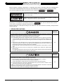
Safety Precautions
(Read these precautions before using.)
Before installing, operating, maintenance or inspecting this product, thoroughly read and understand this
manual and the associated manuals. Also pay careful attention to handle the module properly and safety.
This manual classifies the safety precautions into two categories:
and
.
Indicates that incorrect handling may cause hazardous conditions, resulting in
death or severe injury.
Indicates that incorrect handling may cause hazardous conditions, resulting in
medium or slight personal injury or physical damage.
Depending on circumstances, procedures indicated by
may also be linked to serious results.
In any case, it is important to follow the directions for usage.
Store this manual in a safe place so that you can take it out and read it whenever necessary. Always forward
it to the end user.
1. DESIGN PRECAUTIONS
Reference
• Provide a safety circuit on the outside of the PLC so that the whole system operates to ensure the
safety even when external power supply trouble or PLC failure occurs.
Otherwise, malfunctions or output failures may result in an accident.
1) An emergency stop circuit, a protection circuit, an interlock circuit for opposite movements,
such as normal and reverse rotations, and an interlock circuit for preventing damage to the
machine at the upper and lower positioning limits should be configured on the outside of the
PLC.
2) When the PLC CPU detects an error, such as a watch dog timer error, during self-diagnosis, all
outputs are turned off. When an error that cannot be detected by the PLC CPU occurs in an
input/output control block, output control may be disabled.
Design external circuits and mechanisms to ensure safe operations of the machine in such a
case.
3) When some sort of error occurs in a relay, triac or transistor of the output unit, output may be
kept on or off.
For output signals that may lead to serious accidents, design external circuits and mechanisms
to ensure safe operations of the machine in such cases.
60
Reference
• Observe the following items. Failure to do so may cause incorrect data-writing by noise to PLCs
and result the PLC failure, machine damage or an accident.
1) Do not lay close or bundle with the main circuit line, high-voltage line, or load line.
Noise and Surge induction interfere with the system operation.
Keep a safe distance of least 100 mm (3.94") from the above lines during wiring.
2) Ground the shield wire or shield of a shielded cable at one point on the PLC. However, do not
ground at the same point as high voltage lines.
• Install in a manner which prevents excessive force from being applied to the built-in connectors
dedicated to programming, power connectors and I/O connectors.
Failure to do so may result in wire breakage or failure of the PLC.
(i)
60
Safety Precautions
(Read these precautions before using.)
2. INSTALLATION PRECAUTIONS
Reference
• Make sure to cut off all phases of the power supply externally before starting the installation or
wiring work.
Failure to do so may cause electric shock.
60
Reference
• Fit the extension cables, peripheral device connecting cables, input/output cables and battery
connecting cable securely to the designated connectors.
Contact failures may cause malfunctions.
• Make sure to attach the terminal cover offered as an accessory to the product before turning on
the power or starting the operation after installation or wiring work.
Failure to do so may cause electric shock.
60
3. STARTUP AND MAINTENANCE PRECAUTIONS
Reference
• Do not touch any terminal while the PLC's power is on.
Doing so may cause electrical shock or malfunctions.
• Before cleaning or retightening terminals, externally cut off all phases of the power supply.
Failure to do so may expose you to shock hazard.
• Before modifying the program under operation or performing operation for forcible output, running
or stopping, carefully read the manual, and sufficiently ensure the safety.
An operation error may damage the machine or cause accidents.
• To test Zero-return, JOG operation and Positioning data, throughly read this manual, ensure the
safe system operation
An operation error may damage the machine or cause accidents.
The response, such as the JOG operation, may be slow according to the running state of the
personal computer at the time of the test operation. In the test operation, the PLC performance can
be slower due to the busy state of personal computer.
- End all other applications running except FX Configurator-FP.
- At destination specification (refer to chapter 6), set the transmission speed at 38.4kbps or
higher.
61
Reference
• Do not disassemble or modify the PLC.
Doing so may cause failures, malfunctions or fire.
For repair, contact your local Mitsubishi Electric distributor.
• Before connecting or disconnecting any extension cable, turn off power.
Failure to do so may cause unit failure or malfunctions.
• Before attaching or detaching the following devices, turn off power.
Failure to do so may cause device failure or malfunctions.
- Peripheral devices, expansion boards and special adapters
- I/O extension blocks/units and terminal blocks
(ii)
61
FX Configurator-FP Operation Manual
FX Configurator-FP
Operation Manual
Manual number
JY997D21801
Manual revision
H
Date
7/2012
Foreword
This manual describes FX Configurator-FP Setting/Monitoring Tool and should be read and understood
before attempting installation or operation of software.
Store this manual in a safe place so that you can take it out and read it whenever necessary. Always forward
it to the end user.
This manual confers no industrial property rights or any rights of any other kind, nor does it confer any patent
licenses. Mitsubishi Electric Corporation cannot be held responsible for any problems involving industrial property
rights which may occur as a result of using the contents noted in this manual.
© 2005 MITSUBISHI ELECTRIC CORPORATION
1
FX Configurator-FP Operation Manual
Outline Precautions
• This manual provides information for the use of the FX Configurator-FP. The manual has been written to
be used by trained and competent personnel. The definition of such a person or persons is as follows;
1) Any engineer who is responsible for the planning, design and construction of automatic equipment
using the product associated with this manual should be of a competent nature, trained and qualified
to the local and national standards required to fulfill that role. These engineers should be fully aware of
all aspects of safety with regards to automated equipment.
2) Any commissioning or service engineer must be of a competent nature, trained and qualified to the
local and national standards required to fulfill that job. These engineers should also be trained in the
use and maintenance of the completed product. This includes being completely familiar with all
associated documentation for the said product. All maintenance should be carried out in accordance
with established safety practices.
3) All operators of the completed equipment should be trained to use that product in a safe and
coordinated manner in compliance to established safety practices. The operators should also be
familiar with documentation which is connected with the actual operation of the completed equipment.
Note:
the term 'completed equipment' refers to a third party constructed device which contains or uses
the product associated with this manual
• This product has been manufactured as a general-purpose part for general industries, and has not been
designed or manufactured to be incorporated in a device or system used in purposes related to human life.
• Before using the product for special purposes such as nuclear power, electric power, aerospace, medicine
or passenger movement vehicles, consult with Mitsubishi Electric.
• This product has been manufactured under strict quality control. However when installing the product
where major accidents or losses could occur if the product fails, install appropriate backup or failsafe
functions in the system.
• When combining this product with other products, please confirm the standard and the code, or regulations
with which the user should follow. Moreover, please confirm the compatibility of this product to the system,
machine, and apparatus with which a user is using.
• If in doubt at any stage during the installation of the product, always consult a professional electrical
engineer who is qualified and trained to the local and national standards. If in doubt about the operation or
use, please consult the nearest Mitsubishi Electric distributor.
• Since the examples indicated by this manual, technical bulletin, catalog, etc. are used as a reference,
please use it after confirming the function and safety of the equipment and system. Mitsubishi Electric will
accept no responsibility for actual use of the product based on these illustrative examples.
• This manual content, specification etc. may be changed without a notice for improvement.
• The information in this manual has been carefully checked and is believed to be accurate; however, if you
have noticed a doubtful point, a doubtful error, etc., please contact the nearest Mitsubishi Electric
distributor.
Registration
• Microsoft® and Windows® are either registered trademarks or trademarks of Microsoft Corporation in the
United States and/or other countries.
• The company name and the product name to be described in this manual are the registered trademarks or
trademarks of each company.
2
FX Configurator-FP Operation Manual
Table of Contents
Table of Contents
SAFETY PRECAUTIONS ................................................................................................... (i)
Functions and Use of This Manual .......................................................................................... 6
Associated Manuals.................................................................................................................. 7
Generic Names and Abbreviations Used in Manuals ............................................................ 8
Reading of the Manual ............................................................................................................ 10
Included items ......................................................................................................................... 11
1. Introduction
12
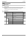
1.1 Product Outline ............................................................................................................................. 12
1.2 Function List.................................................................................................................................. 12
1.3 System Configuration.................................................................................................................... 13
1.3.1 System Configuration .................................................................................................................... 13
1.3.2 Applicable models ......................................................................................................................... 16
1.3.3 Operating System Requirements .................................................................................................. 16
2. Installation, Uninstallation, Startup and Exit
17
2.1 Installation ..................................................................................................................................... 17
2.2 Uninstallation................................................................................................................................. 17
2.3 Starting FX Configurator-FP.......................................................................................................... 18
2.3.1 Starting FX Configurator-FP from the start menu.......................................................................... 18
2.3.2 Starting FX-Configurator-FP from the tool menu in GX Developer. .............................................. 19
2.4 Closing FX Configurator-FP .......................................................................................................... 20
3. Window configuration and basic operation
3.1
3.2
3.3
3.4
3.5
21
Window configuration.................................................................................................................... 21
Menu configuration........................................................................................................................ 21
Tool menus and tool button list ..................................................................................................... 23
Shortcut key list............................................................................................................................. 24
Basic operation ............................................................................................................................. 24
3.5.1 Basic operations in the file data list ............................................................................................... 24
3.5.2 Basic operations in dialog box....................................................................................................... 25
3.6 Help............................................................................................................................................... 25
4. Creating files
26
4.1 Creating a new file ........................................................................................................................ 27
4.1.1 Creating a new file......................................................................................................................... 27
4.1.2 Creating a new file with the data inside 20SSC-H......................................................................... 28
4.2 Opening a stored file ..................................................................................................................... 29
4.3 File storage ................................................................................................................................... 31
4.3.1 Saving files .................................................................................................................................... 31
4.3.2 Saving as files ............................................................................................................................... 32
4.4 Closing files................................................................................................................................... 33
3
FX Configurator-FP Operation Manual
5. Data set
Table of Contents
34
5.1 User unit and Converted pulse data.............................................................................................. 34
5.1.1 User unit ........................................................................................................................................ 34
5.1.2 Converted pulse data .................................................................................................................... 34
5.1.3 Rotation and operation speed of servo motor (Converted pulse data).......................................... 34
5.2 Setting positioning parameters...................................................................................................... 35
5.3 Setting servo parameters .............................................................................................................. 40
5.4 Setting table information ............................................................................................................... 43
5.4.1 The common items in table information......................................................................................... 43
5.4.2 Setting X/Y-axis table information ................................................................................................. 44
5.4.3 Setting XY-axis table information .................................................................................................. 45
5.5 Error check.................................................................................................................................... 46
6. Setting the connection destination
47
7. Read / Write / Verify / Initialize
49
7.1 Data type and storage location ..................................................................................................... 49
7.2 Reading [positioning/servo parameters and table information] ..................................................... 52
7.3 Writing [positioning/servo parameters and table information] ....................................................... 53
7.3.1 Writing to the BFM......................................................................................................................... 53
7.3.2 Writing to the Flash ROM .............................................................................................................. 54
7.4
7.5
7.6
7.7
7.8
Verifying [positioning parameters, servo parameters table information] ....................................... 55
Initializing the BFM and Flash ROM.............................................................................................. 57
Execute system reset of the 20SSC-H.......................................................................................... 58
Sets the servo parameter update stop .......................................................................................... 58
The displayed messages and countermeasures........................................................................... 59
8. Debug in the positioning
60
8.1 Monitor .......................................................................................................................................... 62
8.1.1
8.1.2
8.1.3
8.1.4
Monitoring the operation................................................................................................................ 62
Signal monitor................................................................................................................................ 64
Operation status monitor ............................................................................................................... 65
Monitoring table information .......................................................................................................... 68
8.2 Testing the Operation.................................................................................................................... 69
8.2.1 Switching into test mode................................................................................................................ 69
8.2.2 Operation test in the positioning (except JOG/MPG) .................................................................... 70
8.2.3 Changing the present value........................................................................................................... 73
8.2.4 Speed change ............................................................................................................................... 75
8.2.5 Zero return..................................................................................................................................... 77
8.2.6 JOG/MPG ...................................................................................................................................... 79
8.2.7 Turning OFF m codes.................................................................................................................... 81
8.2.8 Stopping all axis ............................................................................................................................ 81
8.2.9 Error rest........................................................................................................................................ 81
8.2.10 Servo ON/OFF............................................................................................................................. 82
9. Print
83
9.1 Setting the printer.......................................................................................................................... 83
9.2 Printing .......................................................................................................................................... 84
9.2.1 Setting the item to print.................................................................................................................. 84
9.2.2 Printing examples .......................................................................................................................... 87
4
FX Configurator-FP Operation Manual
10. Edit function in data setting
Table of Contents
88
10.1 Cut / Copy / Paste / Select all ..................................................................................................... 88
10.1.1 Cut/Copy...................................................................................................................................... 88
10.1.2 Paste ........................................................................................................................................... 89
10.1.3 Select all ...................................................................................................................................... 90
10.2
10.3
10.4
10.5
10.6
Cursor jump................................................................................................................................. 90
Initializing rows/columns ............................................................................................................. 91
Insert row .................................................................................................................................... 91
Delete row ................................................................................................................................... 92
Initializing data ............................................................................................................................ 93
Warranty................................................................................................................................... 95
Revised History ....................................................................................................................... 96
5
FX Configurator-FP Operation Manual
Functions and Use of This Manual
Functions and Use of This Manual
FX Configurator-FP is the setting/monitor tool for use with a personal computer.
FX Configurator-FP is a setting/monitor tool for the FX3U-20SSC-H positioning block and the servo amplifier
applicable to SSCNETIII can perform the parameter setup, the table information setting, the monitor, and the
test.
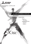
PLC
For wiring and installation of PLC:
FX 3U Series
Hardware manual
Supplied Manual
User’s Manual - Hardware Edition
Additional Manual
FX 3UC Series
FX Configurator-FP
FX3U -20SSC-H
FX3U -20SSC-H
FX Configurator-FP
This Manual
Installation and Operation procedure
Supplied Manual
For specification and parts names
Installation Manual Supplied Manual
Operating instructions and program examples
Operation manual
Describes the servo parameter
setting for the test/monitor mode
and other parameters.
User’s manual
Servo amplifier, Servo motor
Obtain the instruction manual of the servo motor that is to be
connected to your system.
This manual will be needed to set the parameters for the servo
amplifier or write the servo amplifier.
6
FX Configurator-FP Operation Manual
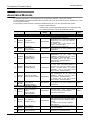
Associated Manuals
Associated Manuals
For detailed explanation of FX Configurator-FP Configuration Software, refer to this manual.
For the hardware information and instruction on the PLC main unit, other special function unit/block, etc., refer
to it's respective manual.
For acquiring required manuals, contact the distributor from who you have purchased the product.
~ Refer to these manuals
{ Refer to the manual required depending on the equipment used
U For detail explanation, refer to an additional manual
Title of manual
Document
number
Description
Model
code
Manual for the Main Module
FX3U Series PLCs Main Unit
U
Supplied
Manual
FX3U Series
Hardware Manual
FX3U Series
Additional
User’s Manual
Manual
- Hardware Edition
FX3UC Series PLCs Main Unit
~
Describes the FX3U Series PLC
specifications for I/O, wiring and installation
extracted from the FX3U User’s Manual JY997D18801
Hardware Edition.
For details, refer to FX3U Series User’s
Manual - Hardware Edition.
Describes the FX3U Series PLC
JY997D16501 specifications for I/O, wiring, installation and
maintenance.
U
Supplied
Manual
FX3UC-32MT-LT
Hardware Manual
(Japanese Only)
JY997D12701
U
Supplied
Manual
FX3UC-32MT-LT-2
Hardware Manual
JY997D31601
U
Supplied
Manual
FX3UC (D, DS, DSS)
Series Hardware Manual
JY997D28601
Describes the FX3UC-32MT-LT PLC
specifications for I/O, wiring and
installation extracted from the FX3UC
User’s Manual - Hardware Edition.
For details, refer to the FX3UC Series
User’s Manual - Hardware Edition
(Japanese Only).
I/O specifications, wiring and installation of
the PLC main unit FX3UC-32MT-LT-2
extracted from the FX3UC Series User's
Manual - Hardware Edition. For detailed
explanation, refer to the FX3UC Series
User's Manual - Hardware Edition.
Describes the FX3UC-(D, DS, DSS) Series
PLC specifications for I/O, wiring and
installation extracted from the FX3UC
User’s Manual - Hardware Edition.
For details, refer to the FX3UC Series
User’s Manual - Hardware Edition.
Describes the FX3UC Series PLC
specifications for I/O, wiring, installation and
maintenance.
FX3UC Series
Additional
User’s Manual
JY997D28701
Manual
- Hardware Edition
Programming for FX3U/FX3UC Series
FX3G / FX3U / FX3UC
Series Programmin
Describes FX3G / FX3U / FX3UC Series
Additional
Manual
JY997D16601 PLC programming for basic/ applied
~
Manual
- Basic & Applied
instructions and devices.
Instruction Edition
Manuals for FX3U-20SSC-H Positioning Block
Describes the FX3U-20SSC-H positioning
block specifications for I/O, power supply
extracted from the FX3U-20SSC-H User’s
Supplied FX3U-20SSC-H
JY997D21101
U Manual Installation Manual
Manual.
For details, refer to the FX3U-20SSC-H
User's Manual.
Additional FX3U-20SSC-H
Describes the FX3U-20SSC-H Positioning
JY997D21301
~
Manual User's Manual
block specifications.
Supplied FX Configurator-FP
Describes the FX Configurator-FP Setting/
JY997D21801
~
Manual Operation Manual
Monitoring Tool operation details.
~
-
09R516
-
-
-
09R519
09R517
-
09R622
09R916
7
FX Configurator-FP Operation Manual
Generic Names and Abbreviations Used in Manuals
Generic Names and Abbreviations Used in Manuals
Generic name or
abbreviation
Description
PLC
FX3U series
FX3U PLC or main unit
FX3UC series
FX3UC PLC or main unit
Generic name for FX3U Series PLC
Generic name for FX3U Series PLC main unit
Generic name for FX3UC Series PLC
Generic name for FX3UC Series PLC main unit
Expansion board
Expansion board
Generic name for expansion board
The number of connectable units, however, depends on the type of main unit.
To check the number of connectable units, refer to the User's Manual - Hardware
Edition of main unit to be used for your system.
Special adapter
Special adapter
Generic name for high-speed input/output special adapter, communication special
adapter, and analog special adapter
The number of connectable units, however, depends on the type of main unit.
To check the number of connectable units, refer to the User's Manual - Hardware
Edition of main unit to be used for your system.
Special function unit/block
Generic name for special function unit and special function block
Special function unit/block or The number of connectable units, however, depends on the type of main unit.
Special extension unit
To check the number of connectable units, refer to the User's Manual - Hardware
Edition of main unit to be used for your system.
Special function unit
Generic name for special function unit
Special function block
Generic name for special function block
The number of connectable units, however, depends on the type of main unit.
To check the number of connectable units, refer to the User's Manual - Hardware
Edition of main unit to be used for your system.
Positioning special
function block
or 20SSC-H
Abbreviated name of FX3U-20SSC-H
Optional unit
Memory cassette
FX3U-FLROM-16, FX3U-FLROM-64, FX3U-FLROM-64L
Battery
FX3U-32BL
FX Series terminal block
FX-16E-TB, FX-32E-TB
Input/output cable
or Input cable
FX-16E-500CAB-S, FX-16E-
CAB, FX-16E-
CAB-R
represents 150, 300, or 500.
Input/output connector
FX2C-I/O-CON, FX2C-I/O-CON-S, FX2C-I/O-CON-SA
Power cable
FX2NC-100MPCB, FX2NC-100BPCB, FX2NC-10BPCB1
Peripheral unit
Peripheral unit
Generic name for programming software, handy programming panel, and indicator
Programming tool
Programming tool
Generic name for programming software and handy programming panel
Programming software
Generic name for programming software
GX Developer
Generic name for SW
D5C-GPPW-J/SW
D5C-GPPW-E programming software
package
FX-PCS/WIN(-E)
Generic name for FX-PCS/WIN or FX-PCS/WIN-E programming software package
Handy programming panel
(HPP)
8
Generic name for FX-20P(-E) and FX-10P(-E)
FX Configurator-FP Operation Manual
Generic Names and Abbreviations Used in Manuals
Generic name or
abbreviation
Description
Setting/Monitoring Tool
Setting/monitoring tool or
FX Configurator-FP
Abbreviated name of FX Configurator-FP Setting/Monitoring Tool
Indicator
GOT1000 series
Generic name for GT16, GT15, GT14, GT11 and GT10
GOT-900 series
Generic name for GOT-A900 series and GOT-F900 series
GOT-A900 series
Generic name for GOT-A900 series
GOT-F900 series
Generic name for GOT-F900 series
ET-940 series
Generic name for ET-940 series
Only manuals in Japanese are available for these products
Drive unit for servo motor and stepping motor
Servo motor
Generic name for servo motor or stepping motor
Including servo amplifier corresponding to SSCNET III.
Servo amplifier
Generic name for servo amplifier corresponding to SSCNET III
MELSERVO series
Generic name for MELSERVO-J3 series and MELSERVO-J4 series
Other unit
Manual pulse generator
Generic name for manual pulse generator (prepared by user)
Manual
FX3U hardware Edition
FX3U Series User's Manual - Hardware Edition
FX3UC hardware Edition
This manual is available only in Japanese.
Programming manual
FX3U/FX3UC Series Programming Manual - Basic and Applied Instructions Edition
Communication control
Edition
FX Series User's Manual - Data Communication Edition
Analog control Edition
FX3U/FX3UC Series User's Manual - Analog Control Edition
Positioning control Edition
FX3U/FX3UC Series User's Manual - Positioning Control Edition
9
FX Configurator-FP Operation Manual
Reading of the Manual
Reading of the Manual
Shows the manual title.
This area shows the
manual title for the page
currently opened.
Shows the title of the chapter and the title
of the section.
This area shows the title of the chapter and the
title of the section for the page currently opened.
Indexes the chapter number.
The right side of each page
indexes the chapter number
for the page currently opened.
1 2 3...
Indicates the procedure steps.
This manual differentiates
the menu and items with
parentheses
[ ] : Refers to the options
in the menu bars,
dialog box items or
FX Configurator-FP
utility menu.
< > : Refers to the dialog
box buttons or the
PC keyboard.
Shows the reference.
The mark of "
" is
expressing the reference
destination and the
reference manual.
The above diagram differs from the actual page, as it is provided for explanation only.
10
FX Configurator-FP Operation Manual
Included items
Included items
Type
(model name)
Product Name
FX Configurator-FP Version 1(1-license product) (CD-ROM)
FX Configurator-FP
(SW1D5C-FXSSC-E)
Quantity
1
Software license agreement
1
Software registration Card (Japanese document)
1
FX Configurator- FP Operation Manual (this manual)
1
11
FX Configurator-FP
1 Introduction
Operation Manual
1.
1.1
1.1 Product Outline
Introduction
Product Outline
The FX Configurator-FP is a personal computer software for FX3U-20SSC-H and servo amplifiers, applicable
to SSCNET ΙΙΙ.
• Setting, monitoring and testing the parameters and table information of FX3U-20SSC-H.
• Setting the parameters of servo amplifiers, applicable to SSCNET ΙΙΙ.
1.2
Function List
Function
File
Edit
Online
Test
Reads, saves and prints the contents
Chapter 4, 9
Setting positioning parameters in
20SSC-H
Sets the operation parameter, pulse rate, feed rate,
MAX/JOG speed
Section 5.1
Setting parameters in servo
amplifiers
Sets the basic, extension, gain/filter and I/O parameters Section 5.2
Setting table information
Sets the X/Y/XY-axis Table information
Reads, writes and verifies the parameter information in
Read/Write/Verify the module data
positioning modules
Operation monitor
Operation
Signal
monitor
Operation status
monitor
Chapter 7
Monitors the present address, present speed, axis
status of all axis
Monitors the module status and servo status
Section 8.1
Monitors the parameters and operation status of all axis
Specifies the table number and tests the operation
Present value change
Tests the feed present value change
Operation
Speed change
test
OPR
Section 5.3
Monitors the present address, status info and servo
Section 8.1
status
Positioning starting
JOG/MPG Operation
12
Reference
New/Open/Save/Print
Monitoring table information
Monitor
Contents
Tests the speed change
Tests the OPR
Tests the operation by JOG/MPG
Section 8.2
FX Configurator-FP
1 Introduction
Operation Manual
1.3 System Configuration
System Configuration
1.3.1
System Configuration
1
Introduction
1.3
2
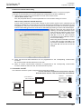
The personal computer can be connected to the FX3U-20SSC-H in two ways.
Install
Uninstall
Start&Exit
1) Direct PLC connection
The personal computer is connected to the PLC main unit directly.
2) Connection via GOT
The personal computer is connected via the GOT’s Transparent mode*1 to the PLC main unit.
*1.
3
Connection via GOT supported by GOT1000 Series only.
This subsection shows the system configurations for direct PLC connection.
1) Connection to
PLC via RS-422
FX3U/FX3UC
FX3U-20SSC-H
Window and
Operation
Config
1. Direct PLC connection
4
Converter/cable
FX3U/FX3UC*2
FX Configurator-FP
FX3U-20SSC-H
5
FX3U-422-BD
FX3U/FX3UC*2
FX3U-20SSC-H
FX3U/FX3UC*3
FX3U-20SSC-H
FX3U/FX3UC*2
FX3U-20SSC-H
RD
Cable
Data set
2) Connection to
PLC via RS-232C
Creating
Files
Standard built-in port
SD
FX3U-232-BD
FX 3U -232ADP
POWER
RD
SD
FX3U-232ADP
USB cable
Setting
The
Connection
3) Connection to
PLC via USB
6
FX3U-***-BD
7
RD
SD
FX3U/FX3UC
FX3U-20SSC-H
Data flow
And
Procedure
FX3U-USB-BD
FX
(RS-422)
PW
SD
RD
FX-USB-AW
MITSUBISHI
FX-USB-AW
8
Standard built-in port
FX3U-20SSC-H
Debug
In the
Positioning
FX3U/FX3UC*2
FX3U-422-BD
Expansion boards (FX3U-***-BD) can not be attached to the FX3UC-
MT/D(SS) and FX3UC-16MR/
D(S)-T PLC.
*3.
The FX3UC-
MT/D(SS) and FX3UC-16MR/D(S)-T PLC can be attached to the FX3U-232ADP
without an expansion board (FX3U-***-BD).
9
Print
*2.
10
Edit
Function
In data
13
FX Configurator-FP
1 Introduction
Operation Manual
1.3 System Configuration
1) The equipment for RS-422 connection
Personal
Computer
Connector
Converter/Cable
Converter
(interface)
RS-232C Cable
PLC Connector
RS-422 Cable
FX-422CAB0[1.5m(4'11")]
F2-232CAB-1[3m(9'10")]
FX-232AWC-H
D-SUB
9Pin
Built-in dedicated
programming
connector of the
main unit
FX3U-422-BD
(D-SUB 25Pin
⇔ MINI DIN 8Pin)
(D-SUB 9Pin
⇔ D-SUB 25Pin)
→ When using FX3U-422-BD, refer to the cautions on communication settings
2) The equipment for RS-232C connection
Personal computer
connector
RS-232C Cable
PLC Connector
FX3U-232-BD
RD
SD
FX-232CAB-1[3m(9'10")]
D-SUB 9Pin
FX3U-232ADP*1
(D-SUB 9Pin ⇔ D-SUB 9Pin)
→ When using FX3U-232-BD, FX3U-232ADP, refer to the cautions on communication settings
*1.
An expansion board is necessary when using FX3U-232ADP except the FX3UC-
MT/D(SS) and
FX3UC-16 MR/D(S)-T PLC.
3) The equipment for USB connection
Personal Computer
Connector
Converter/Cable
USB
Cable*2
Converter (interface)
PLC Connector
Built-in dedicated
programming connector of
the main unit
FX3U-422-BD
FX-USB-AW*3
FX
(RS-422)
MITSUBISHI
PW
SD
RD
(USB connector A plug
[male] ⇔ MINI B plug [male])
FX-USB-AW
USB
FX3U-USB-BD*3
⎯
RD
SD
→ When using FX3U-USB-BD, refer to the cautions on communication settings
→ When using FX3U-422-BD, refer to the cautions on communication settings
14
*2.
The USB cable comes with FX-USB-AW and FX3U-USB-BD.
*3.
For the applicable Windows® Operating Systems, refer to each manual.
FX Configurator-FP
1 Introduction
Operation Manual
1.3 System Configuration
1
Do not change the communication settings for outside modules via parameters or sequence program.
If changed, a communication error occurs between FX Configurator-FP and PLC (20SSC-H).
Introduction
Cautions on communication setting
4) Check that the format of the communication connector to be used is correct.
(D8120, D8400, D8420 = K0)
Also, with peripheral devices, check that parameters for communication setting are correct.
2
Install
Uninstall
Start&Exit
3
Window and
Operation
Config
4
Creating
Files
How to check parameters with GX Developer
A check mark to [Operate communication setting] on [PLC system (2)] tab in [PLC parameter] of GX
Developer disables the communication through the selected port between FX Configurator-FP and
PLC(20SSC-H). When the communication fails, write the parameter that clears the check box [Operate
communication setting] to the PLC via the built-in dedicated programming connector with GX Developer.
When the PLC type of the project is the
FX3U(C), the channel specification (CH1/
CH2) combo box appears. When using
the FX3U -422-BD, FX3U-232-BD, FX3UUSB-BD or the first FX3U-232ADP
connected to the FX3U-CNV-BD, set CH1
and check the settings.
When using the FX3U-232ADP connected
to other than the FX 3U -CNV-BD or the
second FX3U-232ADP connected to the
FX 3U -CNV-BD, set CH2 and check the
settings.
5
Data set
6
6) When an inverter communication instruction is programmed for the corresponding communication
connector, delete the instruction first, and reboot the PLC's power.
This subsection shows the system configurations for Connection via GOT.
→ For the connection equipment for the personal computer,
GOT1000 Series and PLC, refer to the GOT1000 series Manual.
FX3U/FX3UC
FX3U-20SSC-H
8
Debug
In the
Positioning
1) Connection to
GOT via RS-232C
7
Data flow
And
Procedure
2. Connection via GOT
Setting
The
Connection
5) Check that RS and RS2 instructions are not programmed for the corresponding communication
connector.
Do not execute RS and RS2 instructions in this case.
FX Configurator-FP
9
Print
2) Connection to
GOTvia USB
FX3U/FX3UC
FX3U-20SSC-H
10
Edit
Function
In data
15
FX Configurator-FP
1 Introduction
Operation Manual
1.3.2
1.3 System Configuration
Applicable models
• FX3U-20SSC-H type positioning module
• Servo amplifier, applicable to SSCNET III (up to 2pcs)
Connect these servo amplifiers to the FX3U-20SSC-H via SSCNET ΙΙΙ.
1.3.3
Operating System Requirements
Item
Description
32 bit version
• Microsoft® Windows® 95 English version (Service Pack 1 or later)
• Microsoft® Windows® 98 English version
• Microsoft® Windows® Millennium Edition English version
• Microsoft® WindowsNT® 4.0 Workstation English version (Service Pack 3 or later)
• Microsoft® Windows® 2000 professional English version
• Microsoft® Windows® XP English version (Home Edition or Professional)
OS
• Microsoft® Windows Vista® English version (Home Basic, Home Premium, Business,
Ultimate or Enterprise)*1
• Microsoft® Windows® 7 English version (Ultimate, Enterprise, Professional, Home
Premium or Starter)*2
64 bit version
• Microsoft® Windows® 7 English version (Ultimate, Enterprise, Professional or Home
Premium)*2
PC main body
• Microsoft® Windows® 95:
CPU Pentium 133MHz or higher
• Microsoft® Windows® 98:
CPU Pentium 133MHz or higher
• Microsoft® Windows® Millennium Edition:
CPU Pentium 150MHz or higher
• Microsoft® WindowsNT® 4.0:
CPU Pentium 133MHz or higher
• Microsoft® Windows® 2000:
CPU Pentium 133MHz or higher
• Microsoft® Windows® XP:
CPU Pentium 300MHz or higher
®
®
• Microsoft Windows Vista :
®
CPU Pentium 1GHz or better one
®
®
64MB or more
Microsoft®
Windows®
®
®
• Microsoft Windows 7:
• Microsoft Windows 95:
•
Required memory
16
CPU Pentium 1GHz or higher
®
98:
64MB or more
• Microsoft Windows Millennium Edition:
64MB or more
• Microsoft® WindowsNT® 4.0:
64MB or more
• Microsoft® Windows® 2000:
64MB or more
• Microsoft® Windows® XP:
128MB or more
• Microsoft® Windows Vista®:
1GB or more
• Microsoft® Windows® 7:
1GB or more
Hard disk capacity
65MB or more
Disk drive
CD-ROM drive
Display
SVGA (800 × 600) or higher*3
Interface
RS-232C port or USB port
Printer
Printer, applicable to those OS above
Others
Mouse or other pointing device
*1.
*2.
This Operating System is supported in FX Configurator-FP Ver.1.30 or later.
This Operating System is supported in FX Configurator-FP Ver.1.50 or later.
*3.
When using Microsoft® Windows Vista® or Microsoft® Windows® 7, the recommended resolution is
1024 × 768 or more.
FX Configurator-FP
2 Installation, Uninstallation, Startup and Exit
Operation Manual
2.1 Installation
1
2
Installation
Insert the FX Configurator-FP CD-ROM into the CD-ROM drive.
3
Execute SETUP.EXE in the CD-ROM.
Window and
Operation
Config
1
2
3
Installation, Uninstallation, Startup and Exit
Install
Uninstall
Start&Exit
2.1
Introduction
2.
Follow the guidance on the PC display to complete the installation.
Caution
Windows® 95, Windows® 98, Windows® Millennium Edition,
WindowsNT® 4.0, Windows® 2000, Windows® XP
Ver.8.23Z or later
Windows Vista®
Ver.8.62Q or later
Windows® 7
Ver.8.91V or later
5
Uninstallation
6
Setting
The
Connection
1
GX Developer (SW
D5C-GPPW-E)
Version
Data set
2.2
Operating System
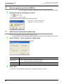
Double-click [Add or Remove Programs] in the control panel.
Note
• [Add/Remove Programs] appears in Windows® 95, Windows® 98, Windows® Millennium Edition, Windows
NT® 4.0 and Windows® 2000.
Select [Change or Remove Programs] in [Add or Remove Programs] window.
Note
8
®
• Click [Add/Remove] on [Add/Remove Programs] property in Windows 95, Windows 98, Windows
Millennium Edition, Windows NT® 4.0 and Windows® 2000.
®
Debug
In the
Positioning
®
• Double-click [Uninstall a program] of [Programs and Features] in Windows Vista® or Windows® 7.
3
7
Data flow
And
Procedure
• [Programs] appears in Windows Vista® or Windows® 7.
2
4
Creating
Files
FX Configurator-FP requires the following version of GX Developer (SW
D5C-GPPW-E) or later:
FX Configurator-FP must be reinstalled if it was first installed prior to the applicable version of GX Developer.
9
Click [FX Configurator-FP] to uninstall.
Print
Note
Double-click [FX Configurator-FP] to uninstall in Windows Vista® or Windows® 7, and go to step 5.
Click [Change/Remove] button.
10
Edit
Function
In data
4
5
Follow the guidance on the PC display to complete the uninstallation.
17
FX Configurator-FP
Operation Manual
2.3
2 Installation, Uninstallation, Startup and Exit
2.3 Starting FX Configurator-FP
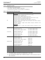
Starting FX Configurator-FP
To start up FX Configurator-FP, follow the 2 procedures below.
2.3.1
1
Starting FX Configurator-FP from the start menu.
Click [Start] → [All Programs] → [MELSOFT Application].
Select [FX Configurator-FP].
Note
[Programs] appears in Windows® OS versions other than When Windows® XP, Windows Vista® or Windows® 7.
2
18
FX Configurator-FP starts up.
FX Configurator-FP
Operation Manual
1
2.3 Starting FX Configurator-FP
1
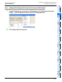
Starting FX-Configurator-FP from the tool menu in GX Developer.
Introduction
2.3.2
2 Installation, Uninstallation, Startup and Exit
Select [Tools] at the menu bar in GX Developer, click [FX special function
utility] → [FX Configurator-FP] to start FX Configurator-FP.
2
Install
Uninstall
Start&Exit
3
Window and
Operation
Config
FX Configurator-FP starts up.
Creating
Files
2
4
5
Data set
6
Setting
The
Connection
7
Data flow
And
Procedure
8
Debug
In the
Positioning
9
Print
10
Edit
Function
In data
19
FX Configurator-FP
Operation Manual
2.4
2 Installation, Uninstallation, Startup and Exit
2.4 Closing FX Configurator-FP
Closing FX Configurator-FP
Note
When closing files or the application while online, i.e. Monitor Mode, Test Mode, the message bellow
appears. Close the application while offline.
1
Select [File] → [Exit].
2
FX Configurator-FP closes.
How to close the application from the title bar
• Right-click on the title bar and select [Close].
• Click
20
on the right edge of the title bar.
FX Configurator-FP
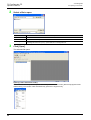
3 Window configuration and basic operation
Operation Manual
3.1 Window configuration
1
Window configuration and basic operation
2
Window configuration
Install
Uninstall
Start&Exit
3.1
Introduction
3.
Title bar
Menu bar
Screen minimize button
Toolbar
Test toolbar
3
Screen maximize button
Drop-down menu
Window and
Operation
Config
Online toolbar
Exits FX Configurator-FP
4
Creating
Files
File data list
Window
5
Data set
Status bar
6
Menu configuration
Setting
The
Connection
3.2
1) File
7
Data flow
And
Procedure
Creates a new file, reads a stored file and prints a
content being edited.
Also shows the history of the files recently
opened.
8
Debug
In the
Positioning
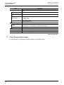
2) Edit
Cuts, copies, pastes and clears row/column, etc.
9
Print
10
Edit
Function
In data
21
FX Configurator-FP
3 Window configuration and basic operation
Operation Manual
3.2 Menu configuration
3) View
Shows /hides the tool bar, status bar and file data
list.
4) Online
Reads/Writes/Verifies, monitors and tests the
module data, etc.
5) Tool
Enables Error check and data initialization.
6) Window
Cascades multiple windows and arranges icons.
7) Help
Shows product information.
22
FX Configurator-FP
3 Window configuration and basic operation
Operation Manual
1
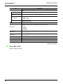
Tool menus and tool button list
Introduction
3.3
3.3 Tool menus and tool button list
The tool bar has the menus below.
Click the toolbar to show (checked)/hide (unchecked).
2
Install
Uninstall
Start&Exit
Shows the file data list
Shows the tool bar
Shows the online tool bar
Shows the test tool bar
3
Shows the status bar
Window and
Operation
Config
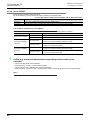
Tool button list
Tool bar
menu
Name
Description
New
Creates a new file
Open
Opens an existing file
Save
Saves the file being edited
Cut
Cuts
Copy
Copies
Paste
Pastes
Print
Prints
Read from module
Reads from the module
Write to module
Writes to the module
Verify module data
Verifies the module data
Monitor On/Off switch
Switches the table information window into monitor mode/edit mode
Test On/Off switch
Switches into test mode
All axis stop
Stops all axis
4
Creating
Files
Tool bar
Tool
button
5
Data set
6
Resets errors at X-axis
Error reset
Y-axis
Resets errors at Y-axis
m code off
X-axis
Turns off the m code at X-axis
m code off
Y-axis
Turns off the m code at Y-axis
Test-operates X-axis
Operation test Y-axis
Test-operates Y-axis
System reset
Execute system reset
9
Print
Operation test X-axis
8
Debug
In the
Positioning
X-axis
7
Data flow
And
Procedure
Test tool bar
Error reset
Setting
The
Connection
Online tool bar
10
Edit
Function
In data
23
FX Configurator-FP
3 Window configuration and basic operation
Operation Manual
3.4
3.4 Shortcut key list
Shortcut key list
Item
Shortcut key
New (N)
Ctrl + N
Open (O)
Ctrl + O
Save (S)
Ctrl + S
Print (P)
Ctrl + P
Cut (T)
Ctrl + X
Copy (C)
Ctrl + C
Paste (V)
Ctrl + V
−
Select all (A)
Ctrl + A
−
Jump (J)
Ctrl + J
Write to module (W)
Ctrl + T
Monitor On/Off (S)
Ctrl + M
File
Edit
Online
3.5
Basic operation
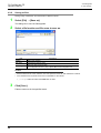
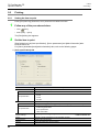
3.5.1
Basic operations in the file data list
[File data list] shows the currently opened file. To open the window, operate as follows. Right-click menu does
not appear for all items below.
1) To display functions, double-click the file name, or click <+>.
(In keyboard operation, select the file name and press <→>)
2) To display the windows, double-click the function name, or click <+>.
(In keyboard operation, select the function name and press <→>)
3) To open the window, double-click the window name.
(In keyboard operation, select the window name and press <Space> bar)
Double-click to
open the window
[File name (e.g. unset file)]
24
Double-click [Edit]
FX Configurator-FP
3 Window configuration and basic operation
Operation Manual
1
Basic operations in dialog box
1)Tab
2)Radio button
2
Install
Uninstall
Start&Exit
1) Tab
Click to switch the items.
2) Radio button
Click <{> to select 1 out of multiple items.
3) Check box
Click <> to put ✔ mark to execute the item.
Introduction
3.5.2
3.6 Help
3)Check box
3
Window and
Operation
Config
4
Creating
Files
5
Data set
4) Text box
Input numbers/characters.
5) List box
Click ▼ to display the selection list, and click
the item to select.
6) Command button
Command buttons appears with <OK> and
<Cancel>, etc. Click those buttons to
execute.
6
5) List box
6) Command button
Setting
The
Connection
4) Text box
Note
In keyboard operations, select the item with <Tab> key. To select more items, use <←>, <→>, <↑>, <↓>
keys.
Data flow
And
Procedure
3.6
7
Help
This function shows FX Configurator-FP version in the product information.
8
Select [Help] → [Product information].
Debug
In the
Positioning
1
The product information appears.
9
Print
10
Edit
Function
In data
25
FX Configurator-FP
4 Creating files
Operation Manual
4.
Creating files
FX Configurator-FP sets and controls the data in the table below.
Data
Description
Positioning
parameter
Parameters for positioning operations, i.e. pulse rate, feed rate and maximum speed of
20SSC-H
Table information
Setting data for table operations of X/Y/XY-axis
Servo parameter
Data to be transferred from 20SSC-H to servo amplifiers, including servo amplifier series, gain/
filter, expansion, I/O, basic setting parameters.
Caution
When creating and saving-as files, the characters and symbols below are not available for the file paths and
names.
/ , : ; * " < > | \ COM LPT AUX CON PRN NUL CLOCK
26
FX Configurator-FP
4 Creating files
Operation Manual
4.1 Creating a new file
Creating a new file
4.1.1
Creating a new file
1
Introduction
4.1
2
This subsection shows how to create a new file.
Install
Uninstall
Start&Exit
Caution
When creating a new file while other files are opened, the following messages appear.
1) When the opened file is not changed
• Click <Yes> to close the current file, and to create a new file.
3
• Click <No> to cancel the operation.
Window and
Operation
Config
4
2) When the opened file is changed
Creating
Files
• Click <Yes> to close the current file without saving, and to create a
new file.
• Click <No> to cancel the operation.
5
Data set
1
Follow any of the procedures below to create a new file.
• Click
(New).
6
Setting
The
Connection
• Select [File] → [New].
FX Configurator-FP creates a new file.
7
Data flow
And
Procedure
8
Debug
In the
Positioning
9
Print
10
Edit
Function
In data
27
FX Configurator-FP
4 Creating files
Operation Manual
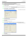
4.1.2
1
4.1 Creating a new file
Creating a new file with the data inside 20SSC-H.
Creating a new file with the data stored in 20SSC-H.
Create a new file.
→ For the details, refer to Subsection 4.1.1.
2
Connect FX3U/3UC PLC with Personal Computer.
3
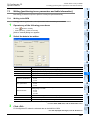
Select [Online] → [Connection setup].
→ For the connection cables configuration, refer to Subsection 1.3.1
Set the destination in [Connection setup] dialog box.
→ For the details, refer to Chapter 6.
4
5
6
7
Click <Comm. Test>.
Check that the communication is properly executed.
Click <OK>.
[Connection setup] dialog box closes.
Select [Online] → [Read from module], and specify the data to be read.
→ For the details, refer to Section 7.2.
Click <OK>.
The specified data is read out.
28
FX Configurator-FP
4 Creating files
Operation Manual
1
Opening a stored file
Introduction
4.2
4.2 Opening a stored file
Opening a stored file.
Caution
2
When opening a stored file while other files are opened, the following messages appear.
Install
Uninstall
Start&Exit
1) When the opened file is not changed
• Click <Yes> to close the current file, and to open a stored file.
• Click <No> to cancel the operation.
3
• Click <Yes> to close the current file without saving, and to open a
stored file.
• Click <No> to cancel the operation.
Window and
Operation
Config
2) When the opened file is changed
4
Creating
Files
Other messages
Messages
5
Conditions
Selected file type is not supported
The extension of the selected file is not supported
Failed to open the file. Because the moduleCan't read the file when the module type is not supported
type is not supported
7
Data flow
And
Procedure
1
Could not open the file.
The following causes are thought
• The specified file does not exist
• The data in the file is completely damaged
• The data is created by other S/W
8
Follow any of the procedures below to open a stored file.
Debug
In the
Positioning
• Click
6
Setting
The
Connection
The file was saved by different FX Configurator-FP version. The file
This file has been made with a newer product can be opened by clicking <OK> but will not be opened properly
version. There is a possibility the data may not <countermeasures>
be read correctly.
Use the FX Configurator-FP version that is the same as or later
than the FX Configurator-FP version used to create the file.
Failed to open the file.
The following causes are thought
• The specified file does not exist
• The data in the file is completely damaged
• The data is created by other S/W
Data set
The allowable No. of characters has been The total amount of the character in the file path and name
exceeded. Set to less than 150 characters
exceeded 150 characters
(Open).
• Select [File] → [Open].
The dialog box to open a file appears.
9
Print
10
Edit
Function
In data
29
FX Configurator-FP
4 Creating files
Operation Manual
2
4.2 Opening a stored file
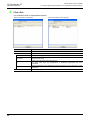
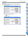
Select a file to open.
Item
Look in
3
Description
Select a file location
File name
Enter the file name to open
Files of type
Select the files of type to open
FX Configurator-FP FILE (*.fsn) : opens data for FX Configurator-FP
Click [Open].
The selected file opens.
Opening a file in Recent file history
A file in Recent file history can be opened. The history shows the latest 4 files. [Recent file] appears at the
default setting. The number of files simultaneously opened is a single file only.
30
FX Configurator-FP
4 Creating files
Operation Manual
1
File storage
Introduction
4.3
4.3 File storage
Storable information
• Versions of files
2
• Module type
Install
Uninstall
Start&Exit
• Positioning parameters
• Servo parameters
• Table information
• Connection Destination
3
Messages
Window and
Operation
Config
Messages
Conditions
The allowable No. of characters has been The total amount of the character in the file path and
exceeded. Set to less than 150 characters
name exceeded 150 characters
4.3.1
4
Could not save the file.
The following causes are thought
• The specified file does not exist
• The data in the file is completely damaged
• The data is created by other S/W
Creating
Files
Failed to save data to the file in selected drive.
The following causes are thought.
• The error occurred while saving project.
• The target Memory is low.
• The medium of selected drive is incorrect.
Saving files
5
Data set
Saving stored files after editing.
1
Follow any of the procedures below to save as files.
• Click
(Save).
6
Setting
The
Connection
• Select → [File] → [Save].
The currently opened file is saved.
When using a floppy disk (FD).
7
Data flow
And
Procedure
When saving a file in a floppy disk, Floppy disk itself needs the same amount of another free space with the
file to be saved, so floppy disk sometimes does not save the file due to the out of disk space.
When the file cannot be saved in floppy disk, save the file once in the hard drive of PC, and copy the file to
floppy disk.
8
Debug
In the
Positioning
9
Print
10
Edit
Function
In data
31
FX Configurator-FP
4 Creating files
Operation Manual
4.3.2
4.3 File storage
Saving as files
Saving newly created files, and stored files in different names.
1
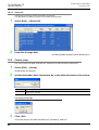
Select [File] → [Save as].
The dialog box to save as files appears.
2
Select a file location and file name to save as.
Item
Description
Look in
Select a file location
File name
Enter the file name to open
Files of type
Select the files of type to open
FX Configurator-FP FILE (*.fsn) : opens data for FX Configurator-FP
Caution
• Set the total amount of the character in the file path and name at 150 characters or below.
• The characters and symbols below are not available for file names.
/ , : ; * " < > | \ COM LPT AUX CON PRN NUL CLOCK
3
Click [Save].
Files are saved as in the specified name.
32
FX Configurator-FP
4 Creating files
Operation Manual
1
Closing files
Introduction
4.4
4.4 Closing files
Closing currently opened files.
Select [File] → [Close].
2
Install
Uninstall
Start&Exit
1
2
A message appears depending on the situation. Follow the message.
1) When the opened file is not changed
• Click <Yes> to close the current file.
3
• Click <No> to cancel the operation.
Window and
Operation
Config
2) When the opened file is changed
Click <Yes> to close the current file without saving.
•
Click <No> to cancel the operation.
4
Creating
Files
•
5
Data set
6
Setting
The
Connection
7
Data flow
And
Procedure
8
Debug
In the
Positioning
9
Print
10
Edit
Function
In data
33
FX Configurator-FP
5 Data set
Operation Manual
5.
5.1 User unit and Converted pulse data.
Data set
This chapter explains the procedures to set and error-check Positioning parameters, Servo parameters and
Table information.
→ For the detail on Positioning parameters and Table information, refer to
FX3U-20SSC-H user's manual.
→ For the detail on Servo parameters, refer to the manual of servo amplifier to be used.
5.1
User unit and Converted pulse data.
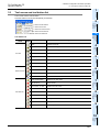
5.1.1
User unit
User units appear as follows, depending on the unit setting and position data magnification.
Unit settings (Positioning units)
Position data
magnification
PLS
1 times
5.1.2
PLS
µm
0.0001 inch
Unit settings (Velocity units)
mdeg
µm ×0.0001 inch
Hz
cm/min
inch/min
10deg/min
Hz
cm/min
inch/min
×10deg/min
mdeg
10 times
×10PLS
×10µm
×0.001 inch
×10mdeg
100 times
×100PLS
×100µm
×0.01 inch
×100mdeg
1000 times
×1000PLS
mm
×0.1 inch
deg
Converted pulse data
For items within a data set range, make sure to set the value does not overlap the range of converted pulse
data.
Pulse conversion procedures are as follows.
1) Travel distance
Travel distance by converted pulse data =
Travel distance(µm, 10-4inch, mdeg) × Position data magnification × (Pulse rate ÷ Feed rate)
2) Operation speed
Operation speed by converted pulse data =
Operation speed(cm/min, inch/min, 10deg/min) × 104 × (Pulse rate ÷ Feed rate) ÷ 60
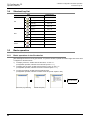
5.1.3
Rotation and operation speed of servo motor (Converted pulse data)
When setting operation speed (incl. Maximum speed, JOG speed, Zero return speed), make sure to set the
value within the Max. rotation speed range of servo motor. The formula to calculate the rotation speed of
servo motor from the operation speed (Converted pulse data) is as follows.
Rotation speed of the servo motor (r/min) =
operation speed by converted pulse data × 60 ÷ resolution per servo motor rotation.
34
Servo amplifier
Resolution per servo motor rotation
MR-J3B
262144
MR-J4B
(J3 compatibility mode)
262144
FX Configurator-FP
5 Data set
Operation Manual
1
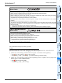
Setting positioning parameters
Introduction
5.2
5.2 Setting positioning parameters
Setting parameters (positioning parameters) for positioning control.
1
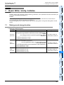
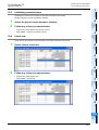
An edit window for positioning parameters appears.
2
2
Install
Uninstall
Start&Exit
Double-click [File name] → [Edit] → [Positioning parameters] in the file data
list.
Set the items for positioning parameters.
To enter texts and select items, double-click the cell.
3
Window and
Operation
Config
→ For positioning parameter details, refer to FX3U-20SSC-H User's Manual.
4
Creating
Files
5
Data set
6
Setting
The
Connection
7
Data flow
And
Procedure
8
Debug
In the
Positioning
9
Print
10
Edit
Function
In data
35
FX Configurator-FP
5 Data set
Operation Manual
5.2 Setting positioning parameters
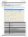
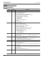
Item
Description
Sets the system of units for positioning for the X/Y-axis.
0: Motor (PLS, Hz)
1: Mechanical (µm, cm/min)
2: Mechanical (0.0001inch, inch/min)
3: Mechanical (mdeg, 10deg/min)
4: Composite (µm, Hz)
5: Composite (0.0001inch, Hz)
6: Composite (mdeg, Hz)
System of unit
Pulse rate
Sets the pulse rate for the X/Y-axis.
Pulse per
Set the resolution per servo motor rotation.
rotation
Setting range : 1~200,000,000 PLS/REV
Feed rate
Travel per Sets the feed rate for the X/Y-axis.
rotation
Setting range : 1~200,000,000 [User unit]*1/REV
Sets the position data magnification for the X/Y-axis.
0: ×1 times
Position data magnification 1: ×10 times
2: ×100 times
3: ×1000 times
Ring counter setting
Sets the Ring counter to valid/invalid for the X/Y-axis.
0: Invalid
1: Valid
Ring counter upper limit Sets the Ring counter upper limit value for the X/Y-axis.
value
Setting range : 1~359,999,999 [User unit]*1
36
Default value
0: Motor (PLS, Hz)
262,144 PLS/REV
52,428,800 PLS/REV
0: ×1 times
0: Invalid
359999PLS
FX Configurator-FP
5 Data set
Operation Manual
5.2 Setting positioning parameters
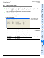
1
Maximum speed
Default value
Sets the maximum speed for the X/Y-axis.
Set the speed at or below the maximum rotation speed*2 of
servo motor.
Setting range : 1~2,147,483,647 [User unit]*1
Set the value within 1~50,000,000Hz in the
converted pulse data.
4,000,000Hz
Sets the JOG speed for the X/Y-axis.
Set the speed at or below the maximum rotation speed*2 of
servo motor.
Setting range : 1~Maximum speed [User unit]*1
Set the value within 1~50,000,000Hz in the
converted pulse data.
2,000,000Hz
3
300ms
Sets the ACC time for the X/Y-axis.
Setting range : 1~5000ms
200ms
ACC time 2
Sets the ACC time for the X/Y-axis.
Setting range : 1~5000ms
200ms
DEC time
Sets the DEC time for the X/Y-axis.
Setting range : 1~5000ms
200ms
DEC time 2
Sets the DEC time for the X/Y-axis.
Setting range : 1~5000ms
200ms
Interpolation time constant
Sets the interpolation time constant for the X/Y-axis.
Setting range : 1~5000ms
100ms
Sudden stop deceleration
time
Sets the sudden stop deceleration time for the X/Y-axis.
Setting range : 1~5000ms
200ms
Sudden stop interpolation
time constant
Sets the sudden stop interpolation time constant for the X/Yaxis.
Setting range : 1~5000ms
100ms
Sudden stop selection
(STOP command)
Set the stop method when the Stop command turns ON
for the X/Y-axis.
0: Normal deceleration stop
1: Sudden stop
0: Normal deceleration stop
Sudden stop selection
(Software limit)
Set the stop method when the software limit turns ON
for the X/Y-axis.
0: Normal deceleration stop
1: Sudden stop
0: Normal deceleration stop
Sudden stop selection
(PLC limit)
Set the stop method when the PLC limit turns ON
for the X/Y-axis.
0: Normal deceleration stop
1: Sudden stop
0: Normal deceleration stop
Sudden stop selection
(Servo amplifier limit)
Set the stop method when the Servo amplifier limit turns ON
for the X/Y-axis.
0: Normal deceleration stop
0: Normal deceleration stop
1: Sudden stop
Interpolation gear ratio
selection
Sets the interpolation gear ratio selection
0: X-axis
1: X-axis, Y-axis
STOP mode
Sets the STOP mode for the X/Y-axis.
0: Positioning end
1: Remaining distance operation
Software limit (upper)
Sets the software limit (upper) address for the X/Y-axis.
Setting range : -2,147,483,648~2,147,483,647 [User unit]*1
Set the value within -2,147,483,648~
2,147,483,647PLS in the converted pulse
data*1.
4
5
6
Setting
The
Connection
ACC time
0: Trapezoid ACC/DEC
Data set
Sets the ACC/DEC mode for the X/Y-axis.
0: Trapezoid ACC/DEC
1: Approximate S curve ACC/DEC
Creating
Files
ACC/DEC mode
Window and
Operation
Config
JOG instruction evaluation Sets the JOG instruction evaluation time for the X/Y-axis.
time
Setting range : 0~5000ms
2
Install
Uninstall
Start&Exit
JOG speed
Description
Introduction
Item
7
Data flow
And
Procedure
Debug
In the
Positioning
0: X-axis
8
9
Print
0: Positioning end
37
10
Edit
Function
In data
0 PLS
FX Configurator-FP
5 Data set
Operation Manual
5.2 Setting positioning parameters
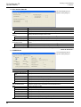
Item
Description
Software limit (lower)
FLS,RLS
External input
selection
38
Sets the software limit (lower) address for the X/Y-axis.
Setting range : -2,147,483,648~2,147,483,647 [User unit]*1
Set the value within -2,147,483,648~
2,147,483,647PLS in the converted pulse
data.*1
Default value
0 PLS
Signal
selection
Sets the FLS and RLS signals to be used/not used in the
servo amplifier. The FLS and RLS on PLC side are always
0: Use signal via FX3U(C)
used.
0: Use signal via FX3U(C)
1: Use signal via FX3U(C) & servo amp
Signal
logic
Sets the FLS and RLS signal logic in the servo amplifier.
0: A-contact (servo amplifier)
1: B-contact (servo amplifier)
1: B-contact
(servo amplifier)
Torque limit
Sets the torque limit for the X/Y-axis.
Setting range : 1~10000×0.1%
Servo ready check
Sets the servo ready check valid/invalid for the X/Y-axis.
0: Invalid
1: Valid
1: Valid
Servo end check
Sets the servo end check valid/invalid for the X/Y-axis.
0: Invalid
1: Valid
1: Valid
Servo end evaluation time
Sets the ON/OFF status in the servo at startup.
Setting range : 1~5000ms
Servo startup
ON/OFF selection
Sets the ON/OFF in the servo for startup.
0: Servo ON at startup.
1: Servo OFF at startup.
Positioning completion
signal output waiting time
Sets the positioning completion signal output waiting time
for the X/Y-axis.
Setting range : 0~5000ms
OPR mode
Sets the OPR mode for the X/Y-axis.
0: DOG
1: Data set
2: Stopper #1
3: Stopper #2
OPR direction
Sets the OPR direction for the X/Y-axis.
0: Decrease present value
1: Increase present value
Machine zero point
address
Sets the OPR address for the X/Y-axis.
Setting range : -2,147,483,648~2,147,483,647 [User unit]*1
Set the value within -2,147,483,648~
2,147,483,647PLS in the converted pulse
data.*1
0 PLS
OPR speed (High speed)
Sets the OPR speed (High speed) for the X/Y-axis.
Set the speed at or below the maximum rotation speed*2 of
the servo motor.
Setting range : 1~Maximum speed [User unit]*1
Set the value within 1~50,000,000Hz in the
converted pulse data. *1
4,000,000Hz
OPR speed (Creep)
Sets the OPR speed (Creep) for the X/Y-axis.
Set the speed at or below the maximum rotation speed*2 of
the servo motor.
Setting range : 1~OPR speed (High speed) [User unit]*1
Set the value within 1~50,000,000Hz in the
converted pulse data. *1
100,000Hz
OPR torque limit value
Sets the torque limit for the X/Y-axis in during OPR.
Setting range : 1~10000×0.1%
3000×0.1%
OPR interlock setting
Sets the OPR interlock to valid/invalid.
0: Invalid
1: Valid
3000×0.1%
5000ms11
0: Servo ON at startup
0ms
0: DOG
0: Decrease present value
1: Valid
FX Configurator-FP
5 Data set
Operation Manual
5.2 Setting positioning parameters
1
Description
Sets the Zero signal count start timing for the X/Y-axis.
Zero signal count start
0: Backward end of DOG
timing
1: Forward end of DOG
Default value
0: Backward end of DOG
Sets the Zero signal count for the X/Y-axis.
Setting range : 0~32767PLS
Zero signal count
1 PLS
0: Use signal via 20SSC-H
Signal
logic
Sets the DOG signal logic for the servo amp.
0: A-contact (servo amplifier)
1: B-contact (servo amplifier)
0: A-contact
(servo amplifier)
DOG switch input logic
Sets the DOG switch input logic for the X/Y-axis.
0: A-contact (20SSC-H)
1: B-contact (20SSC-H)
0: A-contact (20SSC-H)
Servo parameter transfer
mode selection
Sets the Servo parameter transfer mode selection for the
X/Y-axis.
0: Flash ROM → Servo amp
1: BFM → Servo amp
0: Flash ROM Servo amp
DOG External
input selection
3
*2.
For the servo motor rotation speed and the operation speed (converted pulse data), refer to the
following.
→ Refer to Subsection. 5.1.3
→ Refer to Section 5.1.
4
Creating
Files
For the user unit and the converted pulse data, refer to the following.
Window and
Operation
Config
*1.
5
Data set
Display colors of the positioning parameters edit window
Display colors of the positioning parameters edit window have meanings as follows.
Display color of the
characters and frame
2
Install
Uninstall
Start&Exit
Signal
selection
Sets the DOG signal to be used.
0: Use signal via 20SSC-H
1: Use signal via Servo Amplifier
Introduction
Item
Description
6
Nondefault settings with no error.
Red
The content has a setting range error.
Gray
NA items.
• When [System of units] is [Motor], [Pulse rate] and [Feed rate] are not available.
• When [Ring counter setting] is [0: Invalid], [Ring counter upper limit value] is not
available.
• Sets the [Interpolation gear ratio selection] for the X-axis only. The Y-axis is not
available.
• When [Signal selection] in [FLS,RLS External input selection] is [0: Use signal via
FX3U(C)]. [Signal logic] is not available.
• When [Servo end check] is [0: Invalid], [Servo end evaluation time] is not available.
• When [Signal selection] in [DOG External input selection] is [0: Use signal via 20SSC-H],
[Signal logic] is not available.
• When [Signal selection] in [DOG External input selection] is [1: Use signal via Servo
Amplifier], [DOG switch input logic] is not available.
7
8
Debug
In the
Positioning
Black
Data flow
And
Procedure
Default settings.
Setting
The
Connection
Blue
9
Print
10
Edit
Function
In data
39
FX Configurator-FP
Operation Manual
5.3
1
2
5 Data set
5.3 Setting servo parameters
Setting servo parameters
Setting the parameters (servo parameters) to transfer from 20SSC-H to servo amplifiers via SSCNET III.
Double-click [File name] → [Edit] → [Servo parameters] in the file data list.
An edit window for servo parameters appears.
Set the items of servo parameters.
To enter texts and select items, double-click the cell.
→ For servo parameter details, refer to the FX3U-20SSC-H User's Manual and Servo Amplifier
Instruction Manuals.
Servo series [Servo parameters (Basic setting)]
This parameter must be set to transfer information between 20SSC-H and the servo amplifier. Set the servo
parameters according to the servo amplifier being used.
40
5.3 Setting servo parameters
Operation Manual
5 Data set
FX Configurator-FP
1
Introduction
2
Install
Uninstall
Start&Exit
3
Window and
Operation
Config
4
Creating
Files
5
Data set
6
Setting
The
Connection
7
Data flow
And
Procedure
8
Debug
In the
Positioning
9
Print
10
Edit
Function
In data
41
FX Configurator-FP
5 Data set
Operation Manual
5.3 Setting servo parameters
Display colors of the servo parameters edit window
Display colors of the servo parameters edit window have meanings as follows.
Display color of the
characters and frame
Blue
Black
Red
Gray
42
Description
Default settings.
Nondefault settings with no error.
The content has a setting range error.
NA items.
• Depending on the [Gain Changing Selection] content, [Gain Changing Condition] is
not available.
• Depending on the [Servo amplifier series] content, [Forced stop deceleration time
constant] and [Vertical axis freefall prevention compensation amount] are not
available.
FX Configurator-FP
5 Data set
Operation Manual
5.4 Setting table information
1
Setting table information
5.4.1
The common items in table information.
Introduction
5.4
1. The number of table information available for X, Y, XY-axis is as follows.
Table information
Independent operation
300
Y-axis table information
300
XY-axis table information
300
3
2. Items of each operation information for table information
3: Available −: Not available
Operation info
Available axis Address Speed
Arc
radius
Wait time
Jump
m code
destination
X, Y, XY-axis
3
3
−
−
−
−
3
4
X, Y, XY-axis
3
3
−
−
−
−
3
Creating
Files
Arc
center
Window and
Operation
Config
Simultaneous operation at XY-axis
The available table information number
X-axis table information
2
Install
Uninstall
Start&Exit
Setting the table information at X, Y, XY-axis. Set the contents below for each axis.
→ For table information details, refer to the FX3U-20SSC-H user’s manual.
X, Y, XY-axis
3
3
−
−
−
−
3
X, Y, XY-axis
3
3
−
−
−
−
−
X, Y, XY-axis
3
3
−
−
−
−
3
X, Y, XY-axis
−
3
−
−
−
−
−
Interrupt stop*1
Operation at multi-step
speed*4
X, Y, XY-axis
3
3
−
−
−
−
3
X, Y, XY-axis
3
3
−
−
−
−
3
Linear interpolation
XY-axis
3
3*3
−
−
−
−
3
XY-axis
3
3*3
−
−
−
−
3
XY-axis
3
3*3
3
−
−
−
3
XY-axis
3
3*3
3
−
−
−
3
XY-axis
3
3*3
−
3
−
−
3
XY-axis
3
3*3
−
3
−
−
3
X, Y, XY-axis
−
−
−
−
−
−
3
X, Y, XY-axis
3
−
−
−
−
−
3
X, Y, XY-axis
−
−
−
−
−
−
3
X, Y, XY-axis
−
−
−
−
−
−
3
X, Y, XY-axis
X, Y, XY-axis
X, Y, XY-axis
X, Y, XY-axis
X, Y, XY-axis
−
−
−
−
−
−
−
−
−
−
−
−
−
−
−
−
−
−
−
−
3
−
−
−
−
−
3
−
−
−
3
−
3
−
−
10
Edit
Function
In data
43
9
Print
*4.
XY-axis table information also sets X-axis and Y-axis independently.
[Positioning at 2-step speed] and [Interrupt stop at 2-step speed] occupy 2 lines in table information.
Available at X-axis only.
When selecting the items only for X-axis or Y-axis at the operation information in the XY-axis table
information, the items for the other axis are not available.
XY-axis table information is available only for operation at multi-step speed of the X-axis and operation at
multi-step speed of the Y-axis. It is not available for operation at multi-step speed of the XY-axis.
8
Debug
In the
Positioning
*1.
*2.
*3.
7
Data flow
And
Procedure
Machine zero return*1
Present address
changing*1
Absolute address
specification
Incremental address
specification
Dwell
Jump
m code
No processing
End
6
Setting
The
Connection
Linear interpolation
(interrupt)
Circular interpolation
(CNT,CW)
Circular interpolation
(CNT,CCW)
Circular interpolation
(RAD,CW)
Circular interpolation
(RAD,CCW)
5
Data set
Positioning at 1-step
speed*1
Interrupt stop at 1-step
speed*1
Positioning at 2-step
speed*1*2
Positioning at 2-step
speed (Paired line)*1*2
Interrupt stop at 2-step
speed*1*2
Interrupt stop at 2-step
speed (Paired line)*1*2
FX Configurator-FP
5 Data set
Operation Manual
5.4.2
5.4 Setting table information
Setting X/Y-axis table information
Setting X/Y-axis table information
1
Double-click [File name] → [Edit] → [X-axis table information] or [Y-axis table
information] in the file data list.
The selected X or Y-axis table information edit window appears.
2
Set each item for the table information.
To enter texts and select items, double-click the cell.
→ For table information details, refer to FX3U-20SSC-H User's Manual.
This window displays [X-axis table information] edit window.
Item
Table information number
Command code
Sets command code
Address [PLS]
Speed [Hz]
44
Description
No.
Note
→ Refer to Subsection 5.4.1
Sets the address.
Setting range : -2,147,483,648~2,147,483,647 [User unit]*1
Set the value within -2,147,483,648~
2,147,483,647PLS in the converted pulse
data.
[User unit] varies depending on
positioning parameters.
Sets the operation speed.
→ Refer to Section 5.2
*2
Set the speed at or below the maximum rotation speed of
servo motor.
Setting range : 1~Maximum speed [User unit]*1
Set the value within 1~50,000,000Hz in the
converted pulse data.
Time [10ms]
Sets the wait time.
Setting range : 0~32767×10ms
Jump No.
Sets the jump No.
Setting range : 0~299
m code
Sets the m code.
Setting range : -1~32767*3
*1.
For the user unit and the converted pulse data, refer to the following.
*2.
For the servo motor rotation speed and the operation speed (converted pulse data), refer to the
following.
→ Refer to Subsection. 5.1.3
*3.
When the operation information is m code, the setting range is 0~32767.
→ Refer to Section 5.1.
FX Configurator-FP
5 Data set
Operation Manual
1
Setting XY-axis table information
Introduction
5.4.3
5.4 Setting table information
Setting XY-axis table information.
1
Double-click [File name] → [Edit] → [XY-axis table information] in the file data
list.
Install
Uninstall
Start&Exit
XY-axis table information edit window appears.
2
2
Set each item for the table information.
To enter texts and select items, double-click the cell.
3
Window and
Operation
Config
→ For table information details, refer to FX3U-20SSC-H User's Manual.
4
Creating
Files
5
Speed
fx: [Hz] (Upper)
fy: [Hz] (Lower)
Time [10ms]
Jump No.
*1.
For the user unit and the converted pulse data, refer to the following.
*2.
For the servo motor rotation speed and the operation speed (converted pulse data), refer to the following.
→ Refer to Subsection. 5.1.3
*3.
When the operation information is m code, the setting range is 0~32767.
9
Print
m code
8
Debug
In the
Positioning
Arc radius
r: [PLS]
7
Data flow
And
Procedure
Arc center
i: [PLS] (Upper)
j: [PLS] (Lower)
6
Setting
The
Connection
Address
x: [PLS] (Upper)
y: [PLS] (Lower)
Description
Note
→ Refer to Subsection
Table information number
5.4.1
Sets command code
Sets the address.
Setting range : -2,147,483,648~2,147,483,647 [User unit]*1
Set the value within -2,147,483,648~
2,147,483,647PLS in the converted pulse data.
Sets the operation speed.
Set the speed at or below the maximum rotation speed*2 of
servo motor.
Setting range : 1 ~ Maximum speed [User unit]*1
[User unit] varies
Set the value within 1~50,000,000Hz in the depending on positioning
converted pulse data.
parameters.
→ Refer to Section 5.2
Sets the arc center.
Setting range : -2,147,483,648~2,147,483,647 [User unit]*1
Set the value within -2,147,483,648~
2,147,483,647PLS in the converted pulse data.
Sets the arc radius.
Setting range : -2,147,483,648~2,147,483,647 [User unit]*1
Set the value within -2,147,483,648~
2,147,483,647PLS in the converted pulse data.
Sets the wait time.
Setting range : 0~32767×10ms
Sets the jump No.
Setting range : 0~299
Sets the m code.
Setting range : -1~32767*3
Data set
Item
No.
Command code
→ Refer to Section 5.1.
10
Edit
Function
In data
45
FX Configurator-FP
5 Data set
Operation Manual
5.5
5.5 Error check
Error check
Checking the consistency and the incomplete settings in positioning parameters, servo parameters and table
information.
1
Select [Tool] → [Error check].
Error check dialog box appears.
2
Select the item to be checked.
Error check result
Item
Error check items
Positioning parameters
Select the item targeted for Error check
Checks the positioning parameters when ticked off here
Servo parameters
Checks the servo parameters when ticked off here
Table information
Checks the table information when ticked off here
Error check result
3
Description
Displays the items, axis, No. and error items after the error check
Item
Displays the positioning parameter, servo parameter or table information with errors
Axis
Displays X, Y, XY-axis with errors
No.
Displays the table information No. with errors
It is blank here when any error in the positioning parameter or servo parameter
Error items
Displays the details of the error items
<Action>
Executes [Error check]
<Close>
Closes the dialog box
<Jump>
Displays the selected error location
Enabled only with error detection
Click <Action>.
The error check result of the selected item appears.
46
FX Configurator-FP
6 Setting the connection destination
Operation Manual
1
Introduction
6.
Setting the connection destination
2
Setting the connection destination (COM port, transmission speed and the 20SSC-H module No.).
• When connecting the personal computer interfaces to the same COM port in FX Configurator-FP and GX
Developer, set the same baud rate for both. When FX Configurator-FP and GX Developer are running
simultaneously, the baud rate that was set first has priority.
• A communication error may occur depending on the combination of the personal computer model, USB
cable and so on. In that case, refer to the message displayed and perform the operation again.
1
Select [Online] → [Connection setup].
5
Connection setup dialog box appears.
Data set
2
4
Creating
Files
• When the baud rate changes for the fast communication at the serial port of the personal computer, it may
disable the communication, or communication may delay due to too many retries depending on the
personal computer spec. When the fast communication is not enabled, reduce the baud rate and restart
communication.
3
Window and
Operation
Config
• An error may occur in the communication with FX PLC when used with the resume function, suspend
setting, power-saving function and standby mode of the peripheral device. For this reason, do not set the
functions above when communicating with the 20SSC-H.
Install
Uninstall
Start&Exit
Cautions on communication
Set each item.
6
Setting
The
Connection
7
Data flow
And
Procedure
PC side
Description
Default setting
Sets the COM port and transmission speed at PC side.
COM port
Sets the COM port at PC side.
Setting range: COM1 to 10
Transmission Sets the transmission speed.
speed
Setting range: 9.6kbps to 115.2kbps
9
Print
PC side
Selects the personal computer to PLC connection method. (Ver.1.30 or later)
• RS-232C:
Select this connection method when connecting via RS-232C, RS-422, or
RS-232C
USB (FX-USB-AW / FX3U-USB-BD only).
• USB (GOT transparent):
Select this connection method when connecting via the GOT1000 USB
transparent mode.
8
Debug
In the
Positioning
Item
COM1
10
115.2kbps
Edit
Function
In data
47
FX Configurator-FP
6 Setting the connection destination
Operation Manual
Item
Module
Description
Default setting
Sets the module No. for 20SSC-H.
Sets the module No. for 20SSC-H.
Setting range: 0 to 7
0
Time check
Sets the timeout determination time. Unit: second
Setting range: 1 to 9999 seconds
5 seconds
<Comm. Test>
Executes the communication test.
Module No.
Displayed messages
The message below appears depending on the communication setting.
Displayed Message
Description
Cannot communicate with the PLC.
A communication error has occurred. Check the
Execute again after checking the connections with the
connection with PLC, and the communication settings at
PLC.
the destination.
<ES: Error code>
The connected PLC does not support this function.
The connected PLC is not supported.
Please execute again after confirming the version of the
Confirm the version of the PLC.
PLC.
48
The module which supported this function is not found.
Please execute again after confirming the module.
The special function block with assigned module No. is
not 20SSC-H.
Confirm the module No. and the connection between PLC
and 20SSC-H.
Don't change connection data while online.
User has selected [Connection setup] menu while
monitoring.
(displaying operation monitor or the table information edit
window for monitoring).
Select [Connection setup] menu after disrupting the
monitoring.
Module No. is range over.
User set the value outside the module No. range.
Confirm the module No.
Time check is range over.
User set the value outside the time check range.
Confirm the time check setting.
FX Configurator-FP
7 Read / Write / Verify / Initialize
Operation Manual
7.1 Data type and storage location
1
Introduction
7.
Read / Write / Verify / Initialize
Caution
7.1
Data type and storage location
1. Data type and Description
Description
4
Storage location
Table
information
The data for table operation.
• Table information for X-axis.
• Table information for Y-axis.
• Table information for XY-axis.
• The BFM in 20SSC-H
• Flash ROM in 20SSC-H
6
Setting
The
Connection
Servo
parameters
The parameters of servo amp. 20SSC-H transfers servo parameters to
servo amps via SSCNET ΙΙΙ at power on.
→ For servo parameters details, refer to the manual of the
• The BFM in 20SSC-H
servo amp to be used.
→ For setting procedures of servo parameters, refer to Section 5.3. • Flash ROM in 20SSC-H
• Servo parameters for X-axis.
• Servo parameters for Y-axis
5
Data set
Positioning
parameters
The parameters required for positioning control.
→ For positioning parameters details, Refer to FX3U-20SSC-H User's
manual.
• The BFM in 20SSC-H
→ For setting procedures of positioning parameters, refer to
Section 5.2. • Flash ROM in 20SSC-H
• Positioning parameters for X-axis.
• Positioning parameters for Y-axis
Creating
Files
Data type
3
Window and
Operation
Config
When reading or writing data, use the FX Configurator-FP version that is the same as or later than the
FX Configurator-FP used to write data to the 20SSC-H.
Using FX Configurator-FP of earlier version may clear the setting data or change the setting data to invalid
values.
2
Install
Uninstall
Start&Exit
Reading, Writing and Verifying the data (positioning parameters, servo parameters and table information) for
each axis, and initializing the 20SSC-H.
7
Data flow
And
Procedure
8
Debug
In the
Positioning
9
Print
10
Edit
Function
In data
49
FX Configurator-FP
7 Read / Write / Verify / Initialize
Operation Manual
7.1 Data type and storage location
2. Data flow
FX Configurator-FP: Setting/Monitoring tool for 20SSC-H
GX Developer
: Programming software for PLC
1
2
3
FX3U-20SSC-H
Buffer Memory (BFM)
7
- Positioning parameters
- Servo parameters
- Table information
Sequence
program
4
8
- Monitor data
- Control data
FX3U/FX3UC PLC
5
6
Flash ROM
Servo amplifier
Servo amplifier
- Servo parameters
- Servo parameters
- Positioning parameters
- Servo parameters
- Table information
No.
50
Description
c
Read/Write/Monitor/Test the sequence programs with GX Developer.
d
Read out the following data from the 20SSC-H BFM to FX Configurator-FP.
• Positioning parameters
• Servo parameters
• Table information
• Monitor data (Operation status, motion status and input signal status, etc.)
e
Write the following data from FX Configurator-FP to the 20SSC-H BFM.
• Positioning parameters
• Servo parameters
• Table information
• Control data (The present value change, speed change and operation test command, etc.)
f
Read/Write the following data in BFM with sequence program.
• Positioning parameters
• Servo parameters
• Table information
• Monitor data (Operation status, motion status and input signal status, etc.)
• Control data (The present value change, speed change and operation test command, etc.)
g
Store the following BFM data to the Flash ROM by the store command from the sequence
program or FX Configurator-FP.
• Positioning parameters
• Servo parameters
• Table information
h
Positioning/servo parameters and table information transfer from the Flash ROM to the BFM in
20SSC-H at power ON, simultaneously servo parameters transfer to servo amps.
i
Servo parameters transfer to servo amps at power ON.
→ For transfer procedure, refer to the next page.
j
20SSC-H retrieves servo parameters changed at servo amp sides, and updates the servo
parameters in its BFM.
FX Configurator-FP
Operation Manual
7 Read / Write / Verify / Initialize
7.1 Data type and storage location
1
When the power is turned ON or when the system is reset*1, servo parameters stored in the flash ROM are
transferred to the buffer memory. After that, when the servo series (BFM #15000 and #15200) are set to the
corresponding values for the connected servo amplifiers, servo parameters are transferred from the buffer
memory to the servo amplifiers.
The following two transfer methods are available:
• Method to transfer servo parameters set in the sequence program to the servo amplifiers
(Available in 20SSC-H Ver. 1.10 or later)
When turning OFF and then ON the servo parameter transfer command [BFM #519 b9 (X-axis), #619 b9 (Yaxis)], the following parameters in BFM transfer to servo amps.
3
Window and
Operation
Config
System reset is supported in FX3U-20SSC-H Ver. 1.10 or later.
→ Refer to the FX3U-20SSC-H User's Manual for more details on transfer methods
and system reset.
Note
4
1) Servo parameters to be transferred.
Creating
Files
Auto tuning
Auto tuning response
Feed forward gain
Ratio of load inertia moment to servo motor inertia moment.
Model loop gain
Position loop gain
Speed loop gain
Speed integral compensation
Speed differential compensation
5
Data set
-
2
Install
Uninstall
Start&Exit
• Method to transfer servo parameters stored in the flash ROM to the servo amplifiers
*1.
Introduction
How to transfer (write) servo parameters to servo amplifiers
2) The execution condition of the servo parameter transfer command [BFM #519 b9 (X-axis), #619 b9 (Yaxis)] 20SSC-H ignores the servo parameter transfer command during positioning motion.
Setting
The
Connection
3) Servo parameters in transmission [BFM #28 b10 (X-axis), #128 b10 (Y-axis)]
[Servo parameters in transmission] in status information turns ON during servo parameters in
transmission.
→ For details, refer to the FX3U-20SSC-H User's Manual.
6
7
Data flow
And
Procedure
8
Debug
In the
Positioning
9
Print
10
Edit
Function
In data
51
FX Configurator-FP
7 Read / Write / Verify / Initialize
Operation Manual
7.2
7.2 Reading [positioning/servo parameters and table information]
Reading [positioning/servo parameters and table information]
Reading [positioning/servo parameters and table information] from the 20SSC-H BFM.
1
Operate any of the following procedures
• Click
[Read from module].
• Select [Online] → [Read from module].
[Read from module] dialog box appears.
2
Select the data to be read.
Item
COM port
3
Description
Displays [COM port] in [Connection setup] dialog box
Transmission speed
Displays [Transmission speed] in [Connection setup] dialog box
Module No.
Displays [Module No.] in [Connection setup] dialog box
Item
Ticks off the data to be read
Positioning parameters
Ticks off the axis of positioning parameters to be read
• X-axis
• Y-axis
Servo parameters
Ticks off the axis of servo parameters to be read
• X-axis
• Y-axis
Table information
Sets the reading range after ticking off the axis of table information to be read
Setting range : 0 to 299
• X-axis
• Y-axis
• XY-axis
<OK>
Reads the selected data from the BFM
<Cancel>
Cancels selecting and closes the dialog box
Click <OK>.
FX Configurator-FP reads out the selected data from the 20SSC-H BFM.
→ For the displayed messages, refer to Section 7.6.
52
FX Configurator-FP
7 Read / Write / Verify / Initialize
Operation Manual
1
Writing [positioning/servo parameters and table information]
Introduction
7.3
7.3 Writing [positioning/servo parameters and table information]
Data writing procedures comprise of [Write to module] and [Flash ROM write].
7.3.1
Writing to the BFM
2
1
Install
Uninstall
Start&Exit
Writing [positioning parameters, servo parameters table information] to the 20SSC-H BFM.
Operate any of the following procedures
• Click
[Write to module].
• Select [Online] → [Write to module].
3
2
Window and
Operation
Config
[Write to module] dialog box appears.
Select the data to be written.
4
Creating
Files
5
Data set
6
Description
Displays [COM port] in [Connection setup] dialog box
Displays [Transmission speed] in [Connection setup] dialog box
Module No.
Displays [Module No.] in [Connection setup] dialog box
Item
Ticks off the data to be read
7
Data flow
And
Procedure
Transmission speed
Positioning parameters
Ticks off the axis of positioning parameters to be written
• X-axis
• Y-axis
Servo parameters
Ticks off the axis of servo parameters to be written
• X-axis
• Y-axis
Table information
Sets the writing range after ticking off the axis of table information to be written
Setting range : 0 to 299
• X-axis
• Y-axis
• XY-axis
<OK>
Writes the selected data to the BFM
*1.
9
Print
Ticks off when writing the data selected in [Item] to Flash ROM
8
Debug
In the
Positioning
Flash ROM write*1
<Cancel>
Cancels selecting and closes the dialog box
For the flash ROM write, refer to the following.
→ For the flash ROM write, refer to Subsection 7.3.2.
Click <OK>.
FX Configurator-FP writes the selected data to the 20SSC-H BFM.
→ For the displayed messages, refer to Section 7.6.
53
10
Edit
Function
In data
3
Setting
The
Connection
Item
COM port
FX Configurator-FP
7 Read / Write / Verify / Initialize
Operation Manual
7.3.2
7.3 Writing [positioning/servo parameters and table information]
Writing to the Flash ROM
Storing [positioning parameters, servo parameters and table information written beforehand in the 20SSC-H
BFM] in the Flash ROM. After setting up and adjusting the system, it is handy when storing [positioning
parameters, servo parameters and table information] in the BFM.
1
Select [Online] → [Flash ROM write].
[Flash ROM write (BFM -> Flash ROM)] appears.
2
Select the data to be stored in the Flash ROM.
Item
COM port
Transmission speed
Displays [Transmission speed] in [Connection setup] dialog box
Module No.
Displays [Module No.] in [Connection setup] dialog box
Item
3
Description
Displays [COM port] in [Connection setup] dialog box
Ticks off the data to be stored
Positioning parameters
Ticks off the axis of positioning parameters to be stored
• X-axis
• Y-axis
Servo parameters
Ticks off the axis of servo parameters to be stored
• X-axis
• Y-axis
Table information
Ticks off the axis of table information to be stored
• X-axis
• Y-axis
• XY-axis
<OK>
Store the selected data in the BFM
<Cancel>
Cancels selecting and closes the dialog box
Click <OK>.
FX Configurator-FP stores the selected 20SSC-H BFM data in the Flash ROM.
Caution
While data on the X- or Y-axis cannot be written, data on both the X- and Y-axes cannot be written to the flash
ROM.
Wait until data on both the X- and Y-axes can be written, and then write data to the flash ROM.
54
FX Configurator-FP
7 Read / Write / Verify / Initialize
Operation Manual
Verifying [positioning parameters, servo parameters table information]
Verifying the following FX Configurator-FP data with the 20SSC-H BFM.
1
Introduction
7.4
7.4 Verifying [positioning parameters, servo parameters table information]
• Positioning parameters
2
• Servo parameters
1
Install
Uninstall
Start&Exit
• Table information
Operate any of the following procedures
• Click
[Verify module data].
3
• Select [Online] → [Verify module data].
Window and
Operation
Config
[Verify module data] dialog box appears.
2
Select the data to be verified.
4
Creating
Files
5
Data set
6
Setting
The
Connection
Item
Description
Displays [COM port] in [Connection setup] dialog box
Transmission speed
Displays [Transmission speed] in [Connection setup] dialog box
Module No.
Displays [Module No.] in [Connection setup] dialog box
Item
Ticks off the data to be verified
7
Data flow
And
Procedure
COM port
Positioning parameters
Ticks off the axis of positioning parameters to be verified
• X-axis
• Y-axis
Servo parameters
Ticks off the axis of servo parameters to be verified
• X-axis
• Y-axis
Table information
Sets the verifying range after ticking off the axis of table information to be verified
Setting range : 0 to 299
• X-axis
• Y-axis
• XY-axis
Cancels selecting and closes the dialog box
9
Print
verifies the selected data by FX Configurator-FP and the BFM
<Cancel>
Debug
In the
Positioning
<OK>
8
10
Edit
Function
In data
55
FX Configurator-FP
7 Read / Write / Verify / Initialize
Operation Manual
3
7.4 Verifying [positioning parameters, servo parameters table information]
Click <OK>.
The verification result of selected data appears.
When the verification result agrees.
Item
Verify
Verification result
Description
Displays the special function unit/block name of verifying destination
Displays the item, axis, No. and error item when completing the verification
Axis
Displays the disagreed axis by X, Y or XY
Data name
Displays the positioning parameter, servo parameter or table information as a
disagreed data name
No.
Displays the disagreed table information No.
It is blank here when any disagreement in positioning parameters and servo
parameters
Item
Displays the details of the disagreed positioning parameter, servo parameter or table
information
<Close>
56
When the verification result disagrees.
Closes the dialog box
FX Configurator-FP
7 Read / Write / Verify / Initialize
Operation Manual
1
Initializing the BFM and Flash ROM
Initializing [positioning parameters, servo parameters and table information] in the 20SSC-H BFM and Flash
ROM.
2
Select [Online] → [Initialize module].
Install
Uninstall
Start&Exit
1
[Initialize module] dialog box appears.
2
Introduction
7.5
7.5 Initializing the BFM and Flash ROM
Select the data to be initialized.
3
Window and
Operation
Config
4
Creating
Files
5
Data set
Item
COM port
Displays [COM port] in [Connection setup] dialog box
Transmission speed
Displays [Transmission speed] in [Connection setup] dialog box
Module No.
Displays [Module No.] in [Connection setup] dialog box
Item
Ticks off the data to be initialized
Servo parameters
Ticks off the axis of servo parameters to be initialized
• X-axis
• Y-axis
Table information
Ticks off the axis of table information to be initialized
• X-axis
• Y-axis
• XY-axis
Flash ROM write
Ticks off when initializing the Flash ROM data selected in [Item]
<OK>
Initializes the selected data
<Cancel>
Cancels selecting and closes the dialog box
7
8
Debug
In the
Positioning
Ticks off the axis of positioning parameters to be initialized
• X-axis
• Y-axis
Data flow
And
Procedure
Positioning parameters
6
Setting
The
Connection
9
Click <OK>.
Print
3
Description
FX Configurator-FP initializes the selected data in the 20SSC-H BFM.
→ For the displayed messages, refer to Section 7.6.
Caution
57
10
Edit
Function
In data
While data on the X- or Y-axis cannot be initialized, data on both the X- and Y-axes stored in the unit cannot
be initialized.
Wait until data on both the X- and Y-axes can be initialized, and then initialize the unit.
FX Configurator-FP
7 Read / Write / Verify / Initialize
Operation Manual
7.6
7.6 Execute system reset of the 20SSC-H
Execute system reset of the 20SSC-H
→ For more details on system reset details, Refer to the FX3U-20SSC-H User's manual.
1
Operate any of the following procedures
• Click
[System reset].
• Select [Online] → [System reset].
Executing system reset displays the following message.
• Click <Yes> to execute system reset.
• Click <No> to cancel the operation.
7.7
Sets the servo parameter update stop
Sets the servo parameter update stop valid/invalid at X/Y-axis.
→ For more details on servo parameter update stop details, Refer to the FX3U-20SSC-H User's manual.
1
Select [Online] → [Servo parameter update stop].
Servo parameter update stop dialog box appears.
Item
Description
Sets the servo parameter update stop valid/invalid at X/Y-axis.
Servo parameter
• X-axis : Invalid (Allow updating) / Valid (Stop updating)
update stop
• Y-axis : Invalid (Allow updating) / Valid (Stop updating)
2
<OK>
Changes the servo parameter update stop
<Cancel>
Cancels selecting and closes the dialog box
Click <OK>.
The setting of servo parameter update stop is changed to "valid" or "invalid".
58
FX Configurator-FP
7 Read / Write / Verify / Initialize
Operation Manual
1
The displayed messages and countermeasures
Introduction
7.8
7.8 The displayed messages and countermeasures
This section explains the countermeasures for error messages.
Displayed Message
Description
The connected PLC dose not support this function.
The connected PLC is not supported.
Please execute again after confirming the version of the
Confirm the version of the PLC.
PLC.
It is range over.
Check that the value is correct, and execute again.
It is range over.
Because data disagreement has exceeded 100 items, the
The disagreement in verification has exceeded 100.
verify processing is interrupted.
3
Window and
Operation
Config
The special function block with assigned module No. is
The module which supported this function is not found. not 20SSC-H.
Please execute again after confirming the module.
Confirm the module No. and the connection between PLC
and 20SSC-H.
2
Install
Uninstall
Start&Exit
Cannot communicate with the PLC. Execute again after A communication error has occurred.
checking the connections with the PLC.
Check the connection with PLC, and the communication
<ES: Error code>
settings at the destination.
4
Creating
Files
5
Data set
6
Setting
The
Connection
7
Data flow
And
Procedure
8
Debug
In the
Positioning
9
Print
10
Edit
Function
In data
59
FX Configurator-FP
8 Debug in the positioning
Operation Manual
8.
Debug in the positioning
DESIGN PRECAUTIONS
• Provide a safety circuit on the outside of the PLC so that the whole system operates to ensure the safety even
when external power supply trouble or PLC failure occurs.
Otherwise, malfunctions or output failures may result in an accident.
1) An emergency stop circuit, a protection circuit, an interlock circuit for opposite movements, such as normal
and reverse rotations, and an interlock circuit for preventing damage to the machine at the upper and lower
positioning limits should be configured on the outside of the PLC.
2) When the PLC CPU detects an error, such as a watch dog timer error, during self-diagnosis, all outputs are
turned off. When an error that cannot be detected by the PLC CPU occurs in an input/output control block,
output control may be disabled.
Design external circuits and mechanisms to ensure safe operations of the machine in such a case.
3) When some sort of error occurs in a relay, triac or transistor of the output unit, output may be kept on or off.
For output signals that may lead to serious accidents, design external circuits and mechanisms to ensure safe
operations of the machine in such cases.
DESIGN PRECAUTIONS
• Observe the following items. Failure to do so may cause incorrect data-writing by noise to PLCs and result the
PLC failure, machine damage or an accident.
1) Do not lay close or bundle with the main circuit line, high-voltage line, or load line.
Noise and Surge induction interfere with the system operation.
Keep a safe distance of least 100 mm (3.94") from the above lines during wiring.
2) Ground the shield wire or shield of a shielded cable at one point on the PLC. However, do not ground at the
same point as high voltage lines.
• Install in a manner which prevents excessive force from being applied to the built-in connectors dedicated to
programming, power connectors and I/O connectors.
Failure to do so may result in wire breakage or failure of the PLC.
INSTALLATION PRECAUTIONS
• Make sure to cut off all phases of the power supply externally before starting the installation or wiring work.
Failure to do so may cause electric shock.
INSTALLATION PRECAUTIONS
• Fit the extension cables, peripheral device connecting cables, input/output cables and battery connecting cable
securely to the designated connectors.
Contact failures may cause malfunctions.
• Make sure to attach the terminal cover offered as an accessory to the product before turning on the power or
starting the operation after installation or wiring work.
Failure to do so may cause electric shock.
60
FX Configurator-FP
8 Debug in the positioning
Operation Manual
1
2
Install
Uninstall
Start&Exit
3
Window and
Operation
Config
• Do not touch any terminal while the PLC's power is on.
Doing so may cause electrical shock or malfunctions.
• Before cleaning or retightening terminals, externally cut off all phases of the power supply.
Failure to do so may expose you to shock hazard.
• Before modifying the program under operation or performing operation for forcible output, running or stopping,
carefully read the manual, and sufficiently ensure the safety.
An operation error may damage the machine or cause accidents.
• To test Zero-return, JOG operation and Positioning data, throughly read this manual, ensure the safe system
operation
An operation error may damage the machine or cause accidents.
The response, such as the JOG operation, may be slow according to the running state of the personal computer at
the time of the test operation. In the test operation, the PLC performance can be slower due to the busy state of
personal computer.
- End all other applications running except FX Configurator-FP.
- At destination specification (refer to chapter 6), set the transmission speed at 38.4kbps or higher.
Introduction
STARTUP AND MAINTENANCE
PRECAUTIONS
4
Creating
Files
STARTUP AND MAINTENANCE
PRECAUTIONS
• Do not disassemble or modify the PLC.
Doing so may cause failures, malfunctions or fire.
For repair, contact your local Mitsubishi Electric distributor.
• Before connecting or disconnecting any extension cable, turn off power.
Failure to do so may cause unit failure or malfunctions.
• Before attaching or detaching the following devices, turn off power.
Failure to do so may cause device failure or malfunctions.
- Peripheral devices, expansion boards and special adapters
- I/O extension blocks/units and terminal blocks
5
Data set
6
Setting
The
Connection
The monitors/tests debug the positioning operation.
Caution
When the communication error due to the forced termination of FX Configurator-FP, peripheral devices'
power OFF and the connection cable unplugging occurs, all axis stops.
7
Data flow
And
Procedure
1) Operate any of the following procedures when turning OFF m code while monitoring/testing.
- Click
[m code off X-axis] /
[m code off Y-axis].
- Click [Online] → [Test] → [m code off] → [m code off X-axis] / [m code off Y-axis].
- Click
[All axis stop command].
- Click [Online] → [Test] → [All axis stop].
8
Debug
In the
Positioning
2) Operate any of the following procedures when suspending all axis in operation due to peripheral the
devices' error, etc. while monitoring/testing.
9
Print
10
Edit
Function
In data
61
FX Configurator-FP
8 Debug in the positioning
Operation Manual
8.1 Monitor
8.1
Monitor
8.1.1
Monitoring the operation
Monitoring the operation status along each axis.
1
Double-click [File name] → [Monitor] → [Operation monitor] in the file data
list.
[Operation monitor] dialog box appears.
Item
The present address
Description
Displays the present address of X/Y-axis
[Unit : User unit*1]
Operation speed present Displays the operation speed present value along X/Y-axis
value
[Unit : User unit*1]
READY/BUSY
62
Displays READY/BUSY status along X/Y-axis
• READY : Standby
• BUSY : Active
Torque limit storing value
Displays the value stored in the X/Y-axis torque limit
Pattern
Displays the pattern along X/Y-axis
Table No. being executed
Displays the X/Y-axis table No. in execution
It is blank here at other than table operation
Command code
Displays the X/Y-axis command code in table operation
It is blank here at other than table operation
ACC time (ms)
Displays the ACC time set in the X/Y-axis positioning parameter
DEC time (ms)
Displays the DEC time set in the X/Y-axis positioning parameter
ACC time 2(ms)
Displays the ACC time 2 set in the X/Y-axis positioning parameter
DEC time2 (ms)
Displays the DEC time 2 set in the X/Y-axis positioning parameter
Error BFM
Displays the error BFM numbers along the X/Y-axis
It is blank here with no error
FX Configurator-FP
8 Debug in the positioning
Operation Manual
8.1 Monitor
1
Error code
Displays the X/Y-axis error code
Displays 0 with no error
m code
Displays the X/Y-axis ON-state m code
Displays -1 with no ON-state m code
Flash ROM write count
Displays the writing count to Flash ROM
<Signal>
Opens the signal monitor window, available only while monitoring
→ For the signal monitor window, refer to Section 8.1.2
<X-axis Operation status>
Opens the X-axis Operation status monitor window, available only while monitoring
→ For the X-axis Operation status monitor window, refer to 8.1.3
<Y-axis Operation status>
Opens the Y-axis Operation status monitor window, available only while monitoring
→ For the Y-axis Operation status monitor window, refer to 8.1.3
Monitoring
Displays [Monitoring] when monitoring
<Monitor Start>
Starts operation monitor, validating [Signal], [X-axis Operation status], [Y-axis Operation
status] and [Monitor Stop].
<Monitor Stop>
Stops the operation monitor, closing the signal, X/Y-axis operation status monitor widow
Click <Monitor Start>.
The operation monitor starts
4
Creating
Files
→ Refer to Section 5.1.
3
Window and
Operation
Config
For the user unit and the converted pulse data, refer to the following.
2
Install
Uninstall
Start&Exit
*1.
2
Description
Introduction
Item
5
Data set
6
Setting
The
Connection
7
Data flow
And
Procedure
8
Debug
In the
Positioning
9
Print
10
Edit
Function
In data
63
FX Configurator-FP
8 Debug in the positioning
Operation Manual
8.1.2
8.1 Monitor
Signal monitor
Monitoring the status information and servo status information.
1
Double-click [File name] → [Monitor] → [Operation monitor] → [Signal] in the
file data list.
[Status signal] tab in [Signal] dialog box appears.
2
Click the status tab to be monitored.
• Click [Status signal] tab to display the status signal.
• Click [Servo status signal] tab to display the servo status signal.
1. Status signal tab
Item
Description
Unit ready flag
READY/BUSY flag
Zero point return completion flag
Positioning completion flag
Present value overflow
Error flag
Forward rotation pulse outputting
flag
Reverse rotation pulse outputting flag Displays each
flag status
Table operation flag
along X/Y-axis
In m code ON flag
as follows
In remaining distance drive standby on : ON
off : OFF
flag
In speed change processing flag
In target address change
processing flag
In servo parameter transfer flag
In saving flag
Initializing flag
Positioning parameter change
completion flag
2. Servo status signal tab
Item
Description
Zeroing over
Zero speed
Ready ON
Servo ON
Alarm
In-position
Torque control
Absolute position lost
Warning
64
Displays each
flag status
along X/Y-axis
as follows
on : ON
off : OFF
FX Configurator-FP
8 Debug in the positioning
Operation Manual
1
Operation status monitor
Introduction
8.1.3
8.1 Monitor
Monitoring the detailed operation status along X/Y-axis.
1
Double-click [File name] → [Monitor] → [Operation monitor] → [X-axis Operation status] / [ Y-axis Operation status] in the file data list.
Install
Uninstall
Start&Exit
[Axis control data] tab in [X/Y-axis Operation status] dialog box appears.
2
2
Click the tab to be monitored.
• Click [Axis control data] tab to display the axis control data.
3
Window and
Operation
Config
• Click [JOG/MPG] tab to display the JOG/MPG.
• Click [Servo monitor] to display the servo monitor
1. Axis control data tab
This window displays [X-axis
Operation status] dialog box.
4
Creating
Files
5
Data set
Item
Description
Displays target address1 [Unit : User unit]
Displays operation speed1 [Unit : User unit]
Target address2
Displays target address2 [Unit : User unit]
Operation speed2
Displays operation speed2 [Unit : User unit]
Override setting
Displays the override setting [Unit : 0.1%]
→ For [user unit], refer
to Section 5.1
6
Setting
The
Connection
Target address1
Operation speed1
Note
Torque output setting value Displays the torque output setting value [Unit : 0.1%]
Displays the Velocity change value [Unit : User unit]
Displays Target position change value (address)
[Unit : User unit]
Target position change
value (speed)
Displays Target position change value (speed)
[Unit : User unit]
→ For [user unit], refer
to Section 5.1
7
Data flow
And
Procedure
Velocity change value
Target position change
value (address)
8
Debug
In the
Positioning
9
Print
10
Edit
Function
In data
65
FX Configurator-FP
8 Debug in the positioning
Operation Manual
8.1 Monitor
2. Axis monitor data tab
This window displays [X-axis
Operation status] dialog box.
Item
Real current value monitor
Real current address
Received target value
monitor
Description
Displays the Real current value monitor
Displays the Real current address [Unit : User unit*1]
Displays the Received target value monitor
Received target address Displays the Received target address [Unit : User unit*1]
Received target speed
Current address when
an interrupt occurs
Displays the Received target speed [Unit : User unit*1]
In interrupt operation, the current address is stored and displayed when an interrupt
occurs.
Address at interrupt INT0 Displays the address at interrupt INT0. [Unit : User unit*1]
Address at interrupt INT1 Displays the address at interrupt INT1. [Unit : User unit*1]
*1.
For user units and the converted pulse data, refer to the following.
→ Refer to Section 5.1.
3. JOG/MPG tab
This window displays [X-axis
Operation status] dialog box.
Item
JOG
Forward JOG,Reverse
JOG
Displays the JOG monitor
Displays the JOG rotation direction
JOG ACC time
Displays the JOG speed [Unit : User unit*1]
Displays the JOG ACC time [Unit : ms]
JOG speed limit value
Displays the JOG speed limit value [Unit : User unit*1]
JOG speed
JOG DEC time
Operating using acceleration
and deceleration time 2
MPG
Operation status
MPG input selection
MPG input magnification
MPG response
MPG input present value
MPG input frequency
*1.
66
Description
Displays the JOG DEC time [Unit : ms]
Indicates operation using acceleration and deceleration time 2.
Displays the MPG monitor
Displays the Operation status
Displays the MPG input selection
Displays the MPG input magnification
Displays the MPG response
Displays the MPG input present value [Unit : PLS]
Displays the MPG input frequency [Unit : Hz]
For user units and the converted pulse data, refer to the following.
FX Configurator-FP
8 Debug in the positioning
Operation Manual
8.1 Monitor
4. Servo monitor tab
This window displays [X-axis
Operation status] dialog box.
1
Introduction
→ Refer to Section 5.1.
2
Install
Uninstall
Start&Exit
3
Deviation counter value
Window and
Operation
Config
Item
Servo status
Description
Displays Servo status
Displays the deviation counter value [Unit : PLS]
4
Motor revolution number Displays the motor revolution number [Unit : 0.1r/min]
Displays the motor current value [Unit : 0.1%]
Creating
Files
Motor current value
Load ratio
Revival load proportion
Displays the revival load proportion [Unit : %]
Execution load
proportion
Displays the execution load proportion [Unit : %]
Peak load proportion
Displays the peak load proportion [Unit : %]
5
Data set
Error/Warning
Servo parameter error
Displays the servo parameter error
Servo warning code
Displays the servo warning code
6
Setting
The
Connection
7
Data flow
And
Procedure
8
Debug
In the
Positioning
9
Print
10
Edit
Function
In data
67
FX Configurator-FP
8 Debug in the positioning
Operation Manual
8.1.4
8.1 Monitor
Monitoring table information
Monitoring the table information in execution, from the table information edit window.
Caution
Monitor mode doesn't allow each item to change. Change/set the value after switching the window into the
edit mode.
1
Display the X-axis, Y-axis and XY-axis edit window.
→ To display the windows, refer to Section 5.4.
This window displays [X-axis table information edit window].
2
Follow any of the procedures below.
• Click
[Monitor On/Off].
• Select [Online] → [Monitor] → [Monitor On/Off].
X, Y, XY-axis table information edit window changes into monitor mode.
The items in table information edit window of each axis is the same as those in the table information edit window.
- X or Y-axis table information changes into monitor mode when operating from the X-axis table
information or Y-axis table information edit window.
- Only XY-axis table information changes into monitor mode when operating from XY-axis table
information edit window.
→ For table information edit windows, refer to Section 5.4.
This window displays [X-axis table information edit window].
Item
Title bar
⎯
68
Description
Displays X/Y/XY-axis status information
• Operation
• Standby
• Stopped
Highlights table No. line in execution
FX Configurator-FP
8 Debug in the positioning
Operation Manual
1
Testing the Operation
Introduction
8.2
8.2 Testing the Operation
STARTUP AND MAINTENANCE
PRECAUTIONS
5
Switching into test mode
Data set
Switching into FX Configurator-FP into test mode.
1
4
Creating
Files
8.2.1
3
Window and
Operation
Config
Testing each operation in the position start, Feed present value change, velocity change, zero return, JOG
and MPG, switching the 20SSC-H into the test mode while operation monitoring.
2
Install
Uninstall
Start&Exit
• Do not touch any terminal while the PLC's power is on.
Doing so may cause electrical shock or malfunctions.
• Before cleaning or retightening terminals, externally cut off all phases of the power supply.
Failure to do so may expose you to shock hazard.
• Before modifying the program under operation or performing operation for forcible output, running or stopping,
carefully read the manual, and sufficiently ensure the safety.
An operation error may damage the machine or cause accidents.
• To test Zero-return, JOG operation and Positioning data, throughly read this manual, ensure the safe system
operation
An operation error may damage the machine or cause accidents.
The response, such as the JOG operation, may be slow according to the running state of the personal computer at
the time of the test operation. In the test operation, the PLC performance can be slower due to the busy state of
personal computer.
- End all other applications running except FX Configurator-FP.
- At destination specification (refer to chapter 6), set the transmission speed at 38.4kbps or higher.
Follow any of the procedures below.
• Click
6
[Test On/Off].
FX Configurator-FP switches into test mode.
Setting
The
Connection
When switching test mode into monitor mode
7
• Select [Online] → [Test] → [Test On/Off].
Data flow
And
Procedure
1) Follow any of the procedures below when switching the test mode into monitor mode.
- Click
[Test On/Off].
- Select [Online] → [Test] → [Test On/Off].
8
2) FX Configurator-FP starts monitoring
Debug
In the
Positioning
9
Print
10
Edit
Function
In data
69
FX Configurator-FP
8 Debug in the positioning
Operation Manual
8.2.2
8.2 Testing the Operation
Operation test in the positioning (except JOG/MPG)
Testing the operation in the 20SSC-H positioning (except into JOG/MPG) by test mode.
→ For the procedure to switch into test mode, refer to Subsection 8.2.1.
1
Follow any of the procedures below when switching the test mode into
monitor mode.
• Click
[Operation test X-axis] /
[Operation test Y-axis].
• Select [Online] → [Test] → [Operation test] → [Operation test X-axis] / [Operation test Y-axis].
The position start tab in [Operation test X-axis] / [Operation test Y-axis] dialog box appears.
→ For Feed present value CHG tab, refer to Subsection 8.2.3.
→ For velocity change tab, refer to Subsection 8.2.4.
→ For zero return tab, refer to Subsection 8.2.5.
→ For JOG/MPG tab, refer to Subsection 8.2.6.
2
Set the items below.
Item
Monitor item
Present address
Description
Displays present address, Operation speed present value, status information and Error
code
Displays the present address [Unit : User unit*1]
Operation speed present
Displays the operation speed present value [Unit : User unit*1]
value
70
READY/BUSY
Displays status information
• READY : ON
• BUSY : OFF
Table No. being
executed
Displays X/Y-axis table No. in execution
It is blank here at other than table operation
Error code
Displays error codes
Displays 0 with no error
FX Configurator-FP
8 Debug in the positioning
Operation Manual
8.2 Testing the Operation
1
X/Y-axis
Description
Introduction
Item
Sets the positioning operation along X/Y-axis
2
3
4
Creating
Files
Patterns
Sets/displays the operation pattern
Available in [X-axis operation test] only
• Positioning at 1-step speed
• Interrupt stop at 1-step speed
• Positioning at 2-step speed
• Interrupt stop at 2-step speed
• Interrupt stop
• Variable speed operation
• MPG operation*2
• Linear interpolation*2
• Linear interpolation(interrupt)*2
• X-axis table operation (available in [Operation test X-axis] dialog box)
• Y-axis table operation (available in [Operation test y-axis] dialog box)
• XY-axis table operation*2
• Reciprocal movement instruction*3
Window and
Operation
Config
Ticks off to start X and Y-axis simultaneously
[Operation test X-axis] dialog box displays the check box in the Y-axis item
[Operation test Y-axis] dialog box displays the check box in the X-axis item
Install
Uninstall
Start&Exit
Sync start
Table operation start No.
Sets the table operation No. to start table operation
Setting range : 0 to 299
Mode selection
Select the mode of interruption Interrupt stop at 1-step speed
• Rel ring counter INT stop mode
• Abs ring counter INT stop mode
Target address1*4
Sets the Target address1
Setting range : -2,147,483,648 to 2,147,483,647 [User unit]*1
Set the value within -2,147,483,648 to 2,147,483,647PLS in the
converted pulse data*1
Operation speed1*4
Sets the Operation speed1
Set the speed at or below the maximum rotation speed*5 of servo motor
Setting range : 1 to Maximum speed[User unit]*1
Set the value within 1 to 50,000,000Hz in the converted pulse data*1
5
Starts the positioning operation with the pre-set contents
<Cancel remaining distance Cancels the standby in remaining distance operation, and ends the positioning
operation>
operation
Stops all axis
<Stop>
Stops the axis in operation test
<Close>
Cancels the setting, and closes the dialog box
*1.
For the user unit, refer to the following.
9
Print
<All axis stop>
8
Debug
In the
Positioning
<Start>
Setting range : 1 to Maximum speed[User unit]*1
Set the value within 1 to 50,000,000Hz in the converted pulse data*1
7
Data flow
And
Procedure
Operation speed2*4
Sets the Operation speed2
Set the speed at or below the maximum rotation speed*5 of servo motor
Setting
The
Connection
Target address2*4
Sets the Target address2
Setting range : -2,147,483,648 to 2,147,483,647 [User unit]*1
Set the value within -2,147,483,648 to 2,147,483,647PLS in the
converted pulse data*1
Data set
Start using acceleration
Starts using with acceleration and deceleration time 2.
and deceleration time 2
6
→ Refer to Section 5.1.
Not available when ticking off [Simultaneous start].
*3.
*4.
*5.
Reciprocal movement instruction is supported in the 20SSC-H Ver.1.10 or later.
Not available depending on the operation pattern
For the servo motor rotation speed and the operation speed (converted pulse data), refer to the
following.
→ Refer to Section 5.1.3.
71
10
Edit
Function
In data
*2.
FX Configurator-FP
Operation Manual
3
Click <Start>
20SSC-H starts the table operation with the pre-set contents.
72
8 Debug in the positioning
8.2 Testing the Operation
FX Configurator-FP
8 Debug in the positioning
Operation Manual
1
Changing the present value
Changing the present value the 20SSC-H's present value by test mode.
→ For the procedure to switch into test mode, refer to Subsection 8.2.1.
1
2
Follow any of the procedures below.
[Operation test X-axis] /
Install
Uninstall
Start&Exit
• Click
[Operation test Y-axis].
• Select [Online] → [Test] → [Operation test] → [Operation test X-axis] / [Operation test Y-axis].
The position start tab in [Operation test X-axis] / [Operation test Y-axis] dialog box appears.
Click [Feed present value CHG] tab.
4
The display switches into [Feed present value CHG] tab.
Creating
Files
3
3
Window and
Operation
Config
→ For position start tab, refer to Subsection 8.2.2.
→ For velocity change tab, refer to Subsection 8.2.4.
→ For zero return tab, refer to Subsection 8.2.5.
→ For JOG/MPG tab, refer to Subsection 8.2.6.
2
Introduction
8.2.3
8.2 Testing the Operation
Set each item for [Feed present value CHG].
This window displays
[X-axis Operation status]
dialog box.
5
Data set
6
Setting
The
Connection
7
Data flow
And
Procedure
8
Debug
In the
Positioning
9
Print
10
Edit
Function
In data
73
FX Configurator-FP
8 Debug in the positioning
Operation Manual
8.2 Testing the Operation
Item
Monitor item
Present address
Description
Displays present address, Operation speed present value, status information and Error
code
Displays the present address [Unit : User unit*1]
Operation speed present
Displays the operation speed present value [Unit : User unit*1]
value
READY/BUSY
Displays status information
• READY : ON
• BUSY : OFF
Error code
Displays error codes
Displays 0 with no error
Present value change
Address
Changes the present address to the specified one
Sets the present address to be changed
Setting range : -2,147,483,648 to 2,147,483,647 [User unit]*1
<Present value change> Executes the present value change
<All axis stop>
Stops all axis
<Stop>
Stops the axis in operation test
<Close>
Cancels the setting, and closes the dialog box
*1.
4
For the user unit, refer to the following.
Click <Present value change>.
FX Configurator-FP changes the present address to the specified value.
74
→ Refer to Section 5.1.
FX Configurator-FP
8 Debug in the positioning
Operation Manual
1
Speed change
Changing the operation speed and speed override setting in the following operations, by test mode.
→ For the procedure to switch into test mode, refer to Subsection 8.2.1.
→ For more details on each operation and the speed override function, refer to the FX3U-20SSC-H
user's manual.
Operation speed
change
Mechanical zero return (High speed), JOG operation, Positioning at 1-step speed,
Interrupt stop at 1-step speed, Positioning at 2-step speed,
Interrupt stop at 2-step speed, Interrupt stop, Multi-speed operation,
Linear interpolation, Linear interpolation (interrupt), Circular interpolation,
Reciprocal movement instruction
Speed override
Mechanical zero return (High speed), JOG operation, Positioning at 1-step speed,
Interrupt stop at 1-step speed, Positioning at 2-step speed,
Interrupt stop at 2-step speed, Interrupt stop, Variable speed operation,
Multi-speed operation, Linear interpolation, Linear interpolation (interrupt),
Circular interpolation, Reciprocal movement instruction
3
4
[Operation test X-axis] /
Creating
Files
Follow any of the procedures below.
• Click
2
Window and
Operation
Config
1
Applicable operation pattern
Install
Uninstall
Start&Exit
Function
Introduction
8.2.4
8.2 Testing the Operation
[Operation test Y-axis].
• Select [Online] → [Test] → [Operation test] → [Operation test X-axis] / [Operation test Y-axis].
The position start tab in [Operation test X-axis] / [Operation test Y-axis] dialog box appears.
2
Click [Speed CHG] tab.
6
Setting
The
Connection
The display switches into [Speed CHG] tab.
3
5
Data set
→ For position start tab, refer to Subsection 8.2.2.
→ For Feed present value CHG tab, refer to Subsection 8.2.3.
→ For zero return tab, refer to Subsection 8.2.5.
→ For JOG/MPG tab, refer to Subsection 8.2.6.
Set each item for [Speed CHG].
This window displays
[X-axis Operation status]
dialog box.
7
Data flow
And
Procedure
8
Debug
In the
Positioning
9
Print
10
Edit
Function
In data
75
FX Configurator-FP
8 Debug in the positioning
Operation Manual
8.2 Testing the Operation
Item
Monitor item
Present address
Description
Displays present address, Operation speed present value, status information and Error
code
Displays the present address [Unit : User unit*1]
Operation speed present
Displays the operation speed present value [Unit : User unit*1]
value
READY/BUSY
Displays status information
• READY : ON
• BUSY : OFF
Table No. being
executed
Display X/Y-axis table No. in execution
This item is blank when using an operation pattern other than table operation
Error code
Displays error codes
Displays 0 with no error
Speed CHG
Speed change
Sets the Operation speed
When setting the speed at or above the maximum speed, the speed is set to the
maximum speed.
Set the speed at or below the maximum rotation speed*2 of servo motor
Setting range : 1 to Maximum speed[User unit]*1
Set the value within 1 to 50,000,000Hz in the converted pulse data
<REQ. present value
change value>
Executes the speed change
Speed override
Speed override
<REQ. speed override>
<All axis stop>
4
Changes the speed to the specified one
Changes the operation speed override setting
Sets the speed override ratio
Setting range : 1 to 30000 [×0.1%]
Executes the speed override change
Stops all axis
<Stop>
Stops the axis in operation test
<Close>
Cancels the setting, and closes the dialog box
*1.
For the user unit, refer to the following.
*2.
For the servo motor rotation speed and the operation speed (converted pulse data), refer to the
following.
→ Refer to Section 5.1.3.
Click <REQ. present value change value> / <REQ. speed override>.
1. <REQ. present value change value>
FX Configurator-FP changes the operation speed to the specified value.
2. <REQ. speed override>
FX Configurator-FP changes the operation speed at the specified ratio.
76
→ Refer to Section 5.1.
FX Configurator-FP
8 Debug in the positioning
Operation Manual
1
Zero return
Executing the mechanical zero return by the OPR mode specified in test mode.
→ For the procedure to switch into test mode, refer to Subsection 8.2.1.
1
2
Follow any of the procedures below.
[Operation test X-axis] /
Install
Uninstall
Start&Exit
• Click
[Operation test Y-axis].
• Select [Online] → [Test] → [Operation test] → [Operation test X-axis] / [Operation test Y-axis].
The position start tab in [Operation test X-axis] / [Operation test Y-axis] dialog box appears.
Click [OPR] tab.
3
Window and
Operation
Config
→ For position start tab, refer to Subsection 8.2.2.
→ For Feed present value CHG tab, refer to Subsection 8.2.3.
→ For velocity change tab, refer to Subsection 8.2.4.
→ For JOG/MPG tab, refer to Subsection 8.2.6.
2
Introduction
8.2.5
8.2 Testing the Operation
4
The display switches into [OPR] tab.
Creating
Files
This window displays
[X-axis Operation status]
dialog box.
5
Data set
6
Setting
The
Connection
7
Data flow
And
Procedure
8
Debug
In the
Positioning
9
Print
10
Edit
Function
In data
77
FX Configurator-FP
8 Debug in the positioning
Operation Manual
8.2 Testing the Operation
Item
Monitor item
Present address
Description
Displays present address, Operation speed present value, status information and Error
code
Displays the present address [Unit : User unit*1]
Operation speed present
Displays the operation speed present value [Unit : User unit*1]
value
READY/BUSY
Displays status information
• READY : ON
• BUSY : OFF
Error code
Displays error codes
Displays 0 with no error
OPR type
Displays the machine OPR as an OPR type
OPR mode
Displays the OPR mode
(Displays the OPR mode in the 20SSC-H positioning parameter)
• DOG
• Data set
• Stopper #1
• Stopper #2
OPR speed
Displays the OPR speed(High speed) stored in the positioning parameter
[Unit : User unit*1]
OP address
Displays the OP address stored in the positioning parameter
[Unit : User unit*1]
<REQ. OPR>
Executes the mechanical OPR by the specified OPR type
<All axis stop>
Stops all axis
<Stop>
Stops the axis in operation test
<Close>
Cancels the setting, and closes the dialog box
*1.
3
For the user unit, refer to the following.
Click <REQ. OPR>.
20SSC-H starts the OPR.
78
→ Refer to Section 5.1.
FX Configurator-FP
8 Debug in the positioning
Operation Manual
1
JOG/MPG
3
Follow any of the procedures below.
• Click
[Operation test X-axis] /
Window and
Operation
Config
1
[Operation test Y-axis].
• Select [Online] → [Test] → [Operation test] → [Operation test X-axis] / [Operation test Y-axis].
The position start tab in [Operation test X-axis] / [Operation test Y-axis] dialog box appears.
Click [JOG/MPG] tab.
5
Data set
The display switches into [JOG/MPG] tab.
3
4
Creating
Files
→ For position start tab, refer to Subsection 8.2.2.
→ For Feed present value CHG tab, refer to Subsection 8.2.3.
→ For velocity change tab, refer to Subsection 8.2.4.
→ For zero return tab, refer to Subsection 8.2.5.
2
2
Install
Uninstall
Start&Exit
Executing the JOG/MPG in test mode, also confirming the following operations, by JOG/MPG in the
positioning control debug.
→ For the procedure to switch into test mode, refer to Subsection 8.2.1.
• Forward/Reverse rotation direction
• ON/OFF of the external input signals, i.e. Upper/Lower limit switch, zero signal and near-point DOG. signal
• Operation speed test(JOG only)
• Correction of Forward/Reverse rotation Backlash
• Travel distance
Introduction
8.2.6
8.2 Testing the Operation
Set each item for JOG/MPG.
This window displays
[X-axis Operation status]
dialog box.
6
Setting
The
Connection
7
Data flow
And
Procedure
8
Debug
In the
Positioning
9
Print
10
Edit
Function
In data
79
FX Configurator-FP
8 Debug in the positioning
Operation Manual
8.2 Testing the Operation
Item
Description
Displays present address, Operation speed present value, status information and Error
code
Monitor item
Present address
Displays the present address [Unit : User unit*1]
Operation speed present
Displays the operation speed present value [Unit : User unit*1]
value
READY/BUSY
Displays status information
• READY : ON
• BUSY : OFF
Error code
Displays error codes
Displays 0 with no error
JOG operation
Executes the JOG at the specified JOG speed and JOG instruction evaluation time
Sets the JOG speed in 20SSC-H positioning parameter
JOG speed
Setting range : 1 to Maximum speed [User unit*1]
Set the value within 1 to 50,000,000Hz in the converted pulse data.
JOG instruction
evaluation time
Sets the JOG instruction evaluation time in 20SSC-H positioning parameter
Setting range : 0 to 5000ms
Start using acceleration
and deceleration time 2
Starts using with acceleration and deceleration time 2.
<RVS JOG>
Executes reverse JOG while held
<FWD JOG>
Manual pulse operation
MPG input
selection*2
Sets the MPG input selection
0: X input - X opr / Y input - Y opr
1: X input / Y opr
2: X input - X and Y opr
Manual pulse input
magnification
Sets the manual pulse input magnification (numerator/denominator)
Setting range : (Numerator) 1 to 1,000,000
(Denominator) 1 to 1,000,000
MPG response
Sets the MPG response
Setting range : 1 to 32767
MPG Enable flag
Enables the MPG operation when ticked off
<Setup>
Sets the MPG Enable flag and manual pulse input magnification (numerator/
denominator)
<All axis stop>
4
Executes forward JOG while held
Sets the MPG operation
Stops all axis
<Stop>
Stops the axis in operation test
<Close>
Cancels the setting, and closes the dialog box
*1.
For the user unit, refer to the following.
*2.
Available at X-axis operation test only.
→ Refer to Section 5.1.
Click <RVS JOG>, <FWD JOG> or <Setup>.
1. <RVS JOG>
20SSC-H executes the reverse JOG operation at the specified JOG speed and JOG instruction evaluation
time.
2. <FWD JOG>
20SSC-H executes the forward JOG operation at the specified JOG speed and JOG instruction evaluation
time.
3. <Setup>
FX Configurator-FP sets the MPG Enable flag and manual pulse input magnification (numerator/
denominator).
80
FX Configurator-FP
8 Debug in the positioning
Operation Manual
1
Turning OFF m codes
Turning off the m code while monitor/test mode.
→ For the procedure to switch into test mode, refer to Subsection 8.2.1.
1
2
Follow any of the procedures below.
[m code off X-axis] /
Install
Uninstall
Start&Exit
• Click
[m code off Y-axis].
• Select [Online] → [Test] → [m code off] → [m code off X-axis] / [m code off Y-axis].
The m code at the selected axis turns OFF.
3
Stopping all axis
Stopping all axis while test mode.
→ For the procedure to switch into test mode, refer to Subsection 8.2.1.
1
4
Follow any of the procedures below.
Creating
Files
• Click
Window and
Operation
Config
8.2.8
Introduction
8.2.7
8.2 Testing the Operation
[All axis stop command].
• Select [Online] → [Test] → [All axis stop].
All axis stops.
5
Error rest
Resetting the errors in monitor/test mode.
→ For the procedure to switch into test mode, refer to Subsection 8.2.1.
1
Follow any of the procedures below.
[Error reset X-axis] /
6
Setting
The
Connection
• Click
Data set
8.2.9
[Error reset Y-axis].
• Select [Online] → [Test] → [Error reset] → [Error reset X-axis] / [Error reset Y-axis].
The errors are reset at the selected axis.
7
Data flow
And
Procedure
8
Debug
In the
Positioning
9
Print
10
Edit
Function
In data
81
FX Configurator-FP
8 Debug in the positioning
Operation Manual
8.2 Testing the Operation
8.2.10 Servo ON/OFF
Executing servo ON/OFF while test mode.
By servo ON/OFF, the servo motor turns into the state in the following table.
→ For the procedure to switch into test mode, refer to Subsection 8.2.1.
The servo motor state
Servo ON
Locks servo motors and turns them into the standby state
Servo OFF
Unlocks servo motors, and also turns OFF the servo motor electromagnetic brake
The execution conditions for servo ON/OFF
Servo ON/OFF is executable when the execution conditions in the following table are fulfilled.
Menu
All axis Servo ON/OFF
X-axis servo ON/OFF
command
Y-axis servo ON/OFF
command
1
Operation
Execution conditions
Servo ON all axis
• All axis (X and Y-axis) are executable for servo ON
Servo OFF all axis
• X or Y-axis are executable for servo OFF
Servo ON X-axis
• X-axis status information in 20SSC-H is READY
• X-axis servo status is READY ON and servo OFF
Servo OFF X-axis
• X-axis status information in 20SSC-H is READY
• X-axis servo status is servo ON
Servo ON Y-axis
• Y-axis status information in 20SSC-H is READY
• Y-axis servo status is READY ON and servo OFF
Servo OFF Y-axis
• Y-axis status information in 20SSC-H is READY
• Y-axis servo status is servo ON
Follow any of the procedures below depending on the content to be
executed.
• When executing all axis servo ON/OFF
Select [Online] → [Test] → [All axis Servo On/Off].
• When executing servo ON/OFF along the specified axis
Select [Online] → [Test] → [Tool] → [X-axis Servo On/Off command] / [X-axis Servo On/Off command]
Note
3 mark appears on the left of the menu items while the servo is ON.
82
FX Configurator-FP
9 Print
Operation Manual
9.1 Setting the printer
1
Print
2
Setting the printer
Install
Uninstall
Start&Exit
9.1
Introduction
9.
Setting the printer, paper and orientation.
1
Select → [File] → [Printer setup].
3
2
Set each item for the print setup.
→ For print setup details, refer to the OS manual to be used.
→ For the printer property, refer to the printer manual to be used.
Window and
Operation
Config
[Print Setup] dialog box appears.
4
Creating
Files
5
Data set
6
Setting
The
Connection
7
Data flow
And
Procedure
8
Debug
In the
Positioning
9
Print
10
Edit
Function
In data
83
FX Configurator-FP
9 Print
Operation Manual
9.2 Printing
9.2
Printing
9.2.1
Setting the item to print
Printing the positioning parameters, servo parameters and table information.
1
Follow any of the procedures below.
• Click
[Print].
• Select [File] → [Print].
The [Print] dialog box appears.
2
Set the item to print.
[Print] dialog box has [Item specification], [Servo parameters] and [table information] tabs.
Click the tab to set.
For [Servo parameters] and [table information] tabs, refer to the following pages.
1. [Item specification] tab
Item
Axis specification
Specifies the axis data to print
All axis
Prints X, Y and XY-axis data
Axis specification
Prints the ticked axis data
• X-axis
• Y-axis
• XY-axis
Print data
Specifies the data type to print
All item
Prints [Positioning parameters], [Servo parameters] and [Table information]
Item specification
Prints the ticked data item
• Positioning parameters
• Servo parameters
• Table information
<Printer setting>
84
Description
Displays [Printer setting] dialog box
→ Refer to Section 9.1.
<Print>
Outputs to printer depending on the specified contents
<Print preview>
Displays the print preview
<Close>
Closes the dialog box without printing
FX Configurator-FP
9 Print
Operation Manual
9.2 Printing
1
Introduction
2. [Servo parameters] tab
2
Install
Uninstall
Start&Exit
3
Window and
Operation
Config
4
Servo parameters
Description
Specifies the axis data to print
Prints X, Y and XY-axis data
Item specification
Prints the ticked items
• Servo amplifier series
• Basic setting parameters
• Gain/filter setting
• Extension setting parameters
• I/O setting parameters
Displays [Printer setting] dialog box
→ Refer to Section 9.1.
Outputs to printer depending on the specified contents
<Print preview>
Displays the print preview
<Close>
Closes the dialog box without printing
6
Setting
The
Connection
<Print>
5
Data set
All item
<Printer setting>
Creating
Files
Item
7
Data flow
And
Procedure
8
Debug
In the
Positioning
9
Print
10
Edit
Function
In data
85
FX Configurator-FP
9 Print
Operation Manual
9.2 Printing
3. [Table information] tab
Item
Table information No.
All range
Prints all range of the table information
Range specification
Sets the table information printing range for each axis
Each axis setting range : 0 to 299
• X-axis
• Y-axis
• XY-axis
<Printer setting>
86
Description
Specifies the axis data to print
Displays [Printer setting] dialog box
→ Refer to Section 9.1.
<Print>
Outputs to printer depending on the specified contents
<Print preview>
Displays the print preview
<Close>
Closes the dialog box without printing
FX Configurator-FP
Operation Manual
9.2 Printing
1
Printing examples
Introduction
9.2.2
9 Print
1. Positioning parameters printing examples
2
Install
Uninstall
Start&Exit
3
Window and
Operation
Config
4
Creating
Files
2. Servo parameters printing examples
5
Data set
6
Setting
The
Connection
7
Data flow
And
Procedure
3. Table information printing examples
8
Debug
In the
Positioning
9
Print
10
Edit
Function
In data
87
FX Configurator-FP
10 Edit function in data setting
Operation Manual
10.1 Cut / Copy / Paste / Select all
10. Edit function in data setting
10.1
Cut / Copy / Paste / Select all
Partially cutting/copying/pasting the positioning parameter settings. Also Cutting/copying the value in a table
of Microsoft® Excel or Word, and pasting the data cut/copied onto the FX Configurator-FP positioning
parameters.
10.1.1 Cut/Copy
1
Select cells to cut/copy.
2
Follow any of the procedures below.
• Click
[Cut] /
[Copy].
• Right-click to select [Cut] / [Copy].
• Select [Edit] → [Cut] / [Copy].
Caution on cutting
The selected range is treated as default value.
88
FX Configurator-FP
Operation Manual
10 Edit function in data setting
10.1 Cut / Copy / Paste / Select all
1
1
Introduction
10.1.2 Paste
Select cells to paste.
2
Install
Uninstall
Start&Exit
3
Window and
Operation
Config
4
Creating
Files
2
Follow any of the procedures below.
• Click
[Paste].
5
• Right-click to select [Paste].
Data set
• Select [Edit] → [Paste].
6
Setting
The
Connection
7
Data flow
And
Procedure
8
Debug
In the
Positioning
9
Print
10
Edit
Function
In data
89
FX Configurator-FP
10 Edit function in data setting
Operation Manual
10.2 Cursor jump
10.1.3 Select all
Cutting/copying all range of table information, and pasting.
The data items inconsistency between axis disables all-range-paste.
1
Select [Edit] → [Select all].
2
Paste the all range data.
10.2
→ For the procedure to paste, refer to Section 10.1.2.
Cursor jump
The cursor jumps to the table information No. specified by the table information edit window.
1
Select [Edit] → [Jump].
[JUMP] dialog box appears.
2
Set the destination table information No. in the table information edit window.
Item
Jump No.
Description
Sets the destination table information No. in the table information edit window
Setting range : 0 to 299
The Displayed message
When the value input is out of range, the following message appears.
3
Click <OK>.
The cursor jumps to the table information No. specified by JUMP No.
90
FX Configurator-FP
Operation Manual
10.3 Initializing rows/columns
1
Initializing rows/columns
Introduction
10.3
10 Edit function in data setting
Initializing the rows/columns selected in the table information edit window.
Multiple rows/columns are selectable to initialize.
2
Select the part of rows/columns to initialize.
Install
Uninstall
Start&Exit
1
2
Follow any of the procedures below.
• Right-click to select [Clear row] / [Clear column].
• Select [Edit] → [Clear row] / [Clear column].
Window and
Operation
Config
10.4
3
Insert row
Insert rows by the number of rows selected on the table information edit window.
1
4
Select cells to Insert row
Creating
Files
5
Data set
6
Setting
The
Connection
2
Follow any of the procedures below.
• Right-click to select [Insert row].
7
• Select [Edit] → [Insert row].
Data flow
And
Procedure
8
Debug
In the
Positioning
9
Print
10
Edit
Function
In data
91
FX Configurator-FP
10 Edit function in data setting
Operation Manual
10.5
Delete row
Delete rows by the number of rows selected on the table information edit window.
1
Select cells to Delete row.
2
Follow any of the procedures below.
• Right-click to select [Delete row].
• Select [Edit] → [Delete row].
92
10.5 Delete row
FX Configurator-FP
10 Edit function in data setting
Operation Manual
1
Initializing data
Introduction
10.6
10.6 Initializing data
Initializing the positioning parameters, servo parameters and table information along each axis.
1
Select [Tool] → [Initialize data].
2
2
Install
Uninstall
Start&Exit
[Initialize data] dialog box appears.
Set the data to initialize.
3
Window and
Operation
Config
4
Creating
Files
5
Description
Initializes the positioning parameters along the ticked axis
• X-axis
• Y-axis
Servo Parameters
Initializes the servo parameters along the ticked axis
• X-axis
• Y-axis
Table Information
Initializes the table information along the ticked axis
• X-axis
• Y-axis
• XY-axis
6
Setting
The
Connection
Positioning Parameters
Data set
Item
7
Data flow
And
Procedure
8
Debug
In the
Positioning
9
Print
10
Edit
Function
In data
93
FX Configurator-FP
10 Edit function in data setting
Operation Manual
10.6 Initializing data
MEMO
94
FX Configurator-FP
Operation Manual
Warranty
Warranty
Please confirm the following product warranty details before using this product.
1. Gratis Warranty Term and Gratis Warranty Range
If any faults or defects (hereinafter "Failure") found to be
the responsibility of Mitsubishi occurs during use of the
product within the gratis warranty term, the product shall be
repaired at no cost via the sales representative or
Mitsubishi Service Company. However, if repairs are
required onsite at domestic or overseas location, expenses
to send an engineer will be solely at the customer's
discretion. Mitsubishi shall not be held responsible for any
re-commissioning, maintenance, or testing on-site that
involves replacement of the failed module.
[Gratis Warranty Term]
The gratis warranty term of the product shall be for one
year after the date of purchase or delivery to a designated
place. Note that after manufacture and shipment from
Mitsubishi, the maximum distribution period shall be six (6)
months, and the longest gratis warranty term after
manufacturing shall be eighteen (18) months. The gratis
warranty term of repair parts shall not exceed the gratis
warranty term before repairs.
[Gratis Warranty Range]
1)
2)
The range shall be limited to normal use within the
usage state, usage methods and usage environment,
etc., which follow the conditions and precautions, etc.,
given in the instruction manual, user's manual and
caution labels on the product.
Even within the gratis warranty term, repairs shall be
charged for in the following cases.
a) Failure occurring from inappropriate storage or
handling, carelessness or negligence by the user.
Failure caused by the user's hardware or software
design.
b) Failure caused by unapproved modifications, etc.,
to the product by the user.
c) When the Mitsubishi product is assembled into a
user's device, Failure that could have been
avoided if functions or structures, judged as
necessary in the legal safety measures the user's
device is subject to or as necessary by industry
standards, had been provided.
d) Failure that could have been avoided if
consumable parts (battery, backlight, fuse, etc.)
designated in the instruction manual had been
correctly serviced or replaced.
e) Relay failure or output contact failure caused by
usage beyond the specified Life of contact
(cycles).
f) Failure caused by external irresistible forces such
as fires or abnormal voltages, and failure caused
by force majeure such as earthquakes, lightning,
wind and water damage.
g) Failure caused by reasons unpredictable by
scientific technology standards at time of
shipment from Mitsubishi.
h) Any other failure found not to be the responsibility
of Mitsubishi or that admitted not to be so by the
user.
2. Onerous repair term after discontinuation of
production
1)
Mitsubishi shall accept onerous product repairs for
seven (7) years after production of the product is
discontinued.
Discontinuation of production shall be notified with
Mitsubishi Technical Bulletins, etc.
2)
Product supply (including repair parts) is not available
after production is discontinued.
3. Overseas service
Overseas, repairs shall be accepted by Mitsubishi's local
overseas FA Center. Note that the repair conditions at
each FA Center may differ.
4. Exclusion of loss in opportunity and secondary
loss from warranty liability
Regardless of the gratis warranty term, Mitsubishi shall not
be liable for compensation of damages caused by any
cause found not to be the responsibility of Mitsubishi, loss
in opportunity, lost profits incurred to the user or third
person by Failures of Mitsubishi products, special
damages and secondary damages whether foreseeable or
not, compensation for accidents, and compensation for
damages to products other than Mitsubishi products,
replacement by the user, maintenance of on-site
equipment, start-up test run and other tasks.
5. Changes in product specifications
The specifications given in the catalogs, manuals or
technical documents are subject to change without prior
notice.
6. Product application
1)
In using the Mitsubishi MELSEC programmable logic
controller, the usage conditions shall be that the
application will not lead to a major accident even if any
problem or fault should occur in the programmable
logic controller device, and that backup and fail-safe
functions are systematically provided outside of the
device for any problem or fault.
2)
The Mitsubishi programmable logic controller has
been designed and manufactured for applications in
general industries, etc. Thus, applications in which the
public could be affected such as in nuclear power
plants and other power plants operated by respective
power companies, and applications in which a special
quality assurance system is required, such as for
Railway companies or Public service purposes shall
be excluded from the programmable logic controller
applications.
In addition, applications in which human life or
property that could be greatly affected, such as in
aircraft, medical applications, incineration and fuel
devices, manned transportation, equipment for
recreation and amusement, and safety devices, shall
also be excluded from the programmable logic
controller range of applications.
However, in certain cases, some applications may be
possible, providing the user consults their local
Mitsubishi representative outlining the special
requirements of the project, and providing that all
parties concerned agree to the special circumstances,
solely at the users discretion.
95
FX Configurator-FP
Operation Manual
Revised History
Revised History
Date
Revision
Description
12/2005
A
First Edition
1/2007
B
Added items for Ver.1.10
Supports FX3U-20SSC-H (Ver.1.10)
• Ring counter setting added
• Servo parameter transfer mode selection added
• Mode selection added to the Interrupt stop at 1-step speed
• Reciprocal movement instruction added
• Add the following function of MPG operation.
- MPG input selection
- MPG response
• System Reset added
• Servo parameter update stop added
New features
• Insert row / Delete row added
Clerical error correction
7/2007
C
Added items for Ver.1.20
Supports FX3U-20SSC-H (Ver.1.20)
• Sudden stop deceleration time added
• Sudden stop interpolation time constant added
• Sudden stop selection added
• Interpolation gear ratio selection added
• Positioning completion signal output waiting time added
• Positioning parameter change completion flag added
• Real current value monitor added
- Real current address
• Received target value monitor added
- Received target address
- Received target speed
1/2008
D
Added items for Ver.1.30
• Microsoft® Windows Vista® added to the applicable Operating Systems of the
personal computer.
• Connection via GOT1000 (GT15, GT11) series transparent mode added.
9/2009
E
Added items for Ver.1.40
• Servo startup ON/OFF selection added.
• In interrupt operation, current address storing and display added.
• Acceleration and deceleration time 2 setting is added.
1/2010
F
Setting range for positioning parameter (Ring counter upper limit value) changed.
2/2011
G
Added items for Ver.1.50
Supports FX3U-20SSC-H (Ver.1.40)
• Servo parameter added
Microsoft® Windows® 7 32 bit version added to the applicable Operating System of the
personal computer.
7/2012
96
H
Added items for Ver.1.50
Microsoft® Windows® 7 64 bit version added to the applicable Operating System of the
personal computer.
Added items for Ver.1.60
MELSERVO-J4 for MELSERVO series added.
FX Configurator-FP
OPERATION MANUAL
HEAD OFFICE: TOKYO BUILDING, 2-7-3 MARUNOUCHI, CHIYODA-KU, TOKYO 100-8310, JAPAN
HIMEJI WORKS: 840, CHIYODA CHO, HIMEJI, JAPAN
MODEL
SW-FXSSC-O-E
MODEL CODE
09R916
JY997D21801H
(MEE)
Effective Jul. 2012
Specifications are subject to change without notice.