1
SAG589200300
System Application Guide
Spec. No. 589200300 (Model XP4890)
Issue AM, September 21, 2009
Home
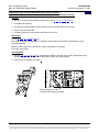
LXP INTRODUCTION
LXP is Emerson Network Power’s next
generation small power platform.
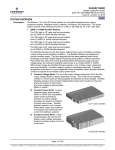
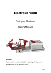
MODEL XP4890 OVERVIEW
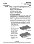
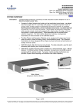
Model XP4890 is a –48VDC Integrated Power
System that operates with LXP Power
Conversion Units (PCUs) powered from
120/208/240 VAC and featuring constantpower design.
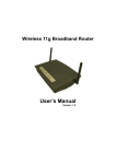
This single-shelf Power System provides up to 5250 watts of power conversion and distribution.
PCUs:
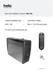
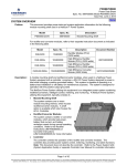
The heart of this system is the LXP Power Conversion Unit (PCU). Available in three output ratings, the LXP
PCU operates at 0.99 power factor and with less than 5% THD. Designed for positive ground applications, the
PCU normal output voltage ranges from 47 to 58 volts, with an equalize voltage adjustable down to 47 volts,
and a test voltage adjustable down to 45 volts.
Each PCU monitors the input voltage and automatically selects one of two operating modes. Full output is
available for nominal 208/240VAC operation. A reduced power mode provides half power for nominal
120VAC input. For 208/240V applications, the reduced-power mode means that the PCU does not inhibit at
low line, but reduces its output to half.
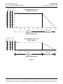
The system can be set by the user to operate the PCUs in either the Power Limit or Current Limit mode.
Power Limit Mode: With the system set to the Power Limit mode, the PCUs will operate as a constantvoltage source or a constant-power source, depending upon load demands. Transition between source
types is completely automatic.
•
Constant Voltage Source: For any initial output voltage setting from 47 to 58 volts, output voltage
remains constant regardless of load. This is the normal operating condition, in which loads are being
supplied and batteries are float charged. PCUs will operate as a constant-voltage source unless load
increases to the point where the product of load current and output voltage equals the specified full
output power rating.
•
Constant Power Source: As load increases above specified full output power rating, output current
continues to increase, but output voltage decreases as required to maintain constant output power.
This will continue until output current reaches a predetermined (non-adjustable) limit. Load demands
above this point result in output voltage dropping rapidly to maintain current and power within their
limits.
Current Limit Mode: With the system set to the Current Limit mode, the PCUs will operate as a
constant-voltage source or a constant-current source, depending upon load demands. Transition
between source types is completely automatic.
•
Constant Voltage Source: For any initial output voltage setting from 47 to 58 volts, output voltage
remains constant regardless of load. This is the normal operating condition, in which loads are being
supplied and batteries are float charged. PCUs will operate as a constant-voltage source unless load
current increases to the user-adjustable current limit setpoint (maximum is 110% of full load rating).
•
Constant Current Source: If load current increases above the current limit setting, output voltage
decreases linearly to maintain output current at current limit.
PCUs will continue to operate in higher ambient temperatures at reduced power. Refer to Paragraph 2.3.6(C)
for further information regarding thermal power and current limiting.
Page 1 of 105
This document is property of Emerson Network Power, Energy Systems, North America, Inc. and contains confidential and proprietary information owned by Emerson Network Power, Energy
Systems, North America, Inc. Any copying, use, or disclosure of it without the written permission of Emerson Network Power, Energy Systems, North America, Inc. is strictly prohibited.
SAG589200300
Issue AM, September 21, 2009
System Application Guide
Spec. No. 589200300 (Model XP4890)
Home
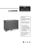
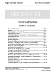
MCA:
The Model LXC300 MCA controls the steady state output voltage to within 0.5% of any setting, from no load
to full load.
The MCA provides a two-line vacuum fluorescent display and keypad for local user interface, as well as an
integrated Web Interface for remote access via an Ethernet connection.
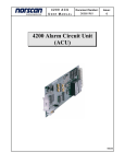
Distribution:
Power distribution is provided through up to (4) bullet nose circuit breakers or TPS/TLS fuses, as well as up to
(10) GMT alarm-type fuses. Battery protection is available through Low Voltage Load Disconnect or Low
Voltage Battery Disconnect options.
Ringing:
An in-shelf ringing generator option provides 50VA of continuous ringing power with built-in redundancy and
transfer capability.
Page 2 of 105
This document is property of Emerson Network Power, Energy Systems, North America, Inc. and contains confidential and proprietary information owned by Emerson Network Power, Energy
Systems, North America, Inc. Any copying, use, or disclosure of it without the written permission of Emerson Network Power, Energy Systems, North America, Inc. is strictly prohibited.
System Application Guide
Spec. No. 589200300 (Model XP4890)
SAG589200300
Issue AM, September 21, 2009
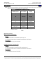
Family:
LXP
Spec. No.:
589200300
Model:
XP4890
Output Voltage:
–48VDC, nominal
Output Capacity:
System:
114 Amperes, 5,250 Watts max. (208/240V)
49 Amperes, 2250 Watts max. (120V)
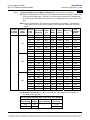
List 53 PCU (LXP1000)
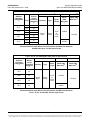
16.7A @ -58.0VDC to 21.7A @ -46VDC, 1000 Watts max. (208/240V)
8.35 @ -58.0VDC to 10.85A @ -46VDC, 500 Watts max. (120V)
List 55 PCU (LXP1500):
25A @ -58.0VDC to 32.6A @ -46VDC, 1500 Watts max. (208/240V)
12.5 @ -58.0VDC to 16.3A @ -46VDC, 750 Watts max. (120V)
List 56 PCU (LXP1750):
29.2A @ -58.0VDC to 38.0A @ -46VDC, 1750 Watts max. (208/240V)
12.5 @ -58.0VDC to 16.3A @ -46VDC, 750 Watts max. (120V)
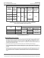
Total Distribution:
List 1, 2, 3, 4, 21, 22, 23, 24: 100 Amperes max.
List 6, 7:
80 Amperes @ 50C° or less ambient
60 Amperes @ above 50C° ambient.
List 11, 12, 13, 14: 100 Amperes @ 50C° or less ambient
90 Amperes @ above 50C° ambient.
Agency Approval:
UL 60950 Recognized, CAN/CSA 22.2
Framework Type:
Equipment Shelf for Relay Rack Mounting
Mounting Width:
23”
Mounting Depth:
12”
Mounting Height:
3.5”
Front Projection:
5”
Access:
List 1, 2, 3, 4, 21, 22, 23, 24: Front, sides, top for installation, front for
operation and maintenance.
List 6, 7: Front, sides for installation, front for operation and
maintenance.
List 11, 12, 13, 14: Front for installation, operation and maintenance.
Expansion Shelves Available:
None
Control:
Microprocessor
Color:
Textured Cool Gray
List Options:
120V Line Cord Kit, 208/240V Line Cord Kit, Local Computer Access
Cable, MCA Control Bus Cable, Analog Battery Temperature Probe,
Digital Battery Temperature Probe, Battery Temperature Probe
Concentrator Module, 50 VA Redundant Ringing Generator Module
Accessory Options:
Circuit Breakers, Fuses, Lugs, Replacement MCA Control Bus
Termination Plug, Load Shed Card, Ringing Distribution Module,
AP6C57EA/EB Ring & Distribution Module, Field-Replaceable
Components
Environment:
Specification Compliant Full
Output:
-20°C to +65°C (-4°F to +149°F)
Reduced Load:
+65°C to +80°C (+149°F to +176°F)
Page 3 of 105
This document is property of Emerson Network Power, Energy Systems, North America, Inc. and contains confidential and proprietary information owned by Emerson Network Power, Energy
Systems, North America, Inc. Any copying, use, or disclosure of it without the written permission of Emerson Network Power, Energy Systems, North America, Inc. is strictly prohibited.
SAG589200300
Issue AM, September 21, 2009
System Application Guide
Spec. No. 589200300 (Model XP4890)
Home
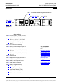
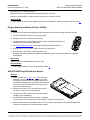
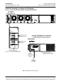
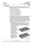
589200300
List 72: 50VA Redundant Ringing Generator Module
List 53, 55, 56: PCU
List 32: MCA
List 1, 2, 3, 4,
6, 7, 11, 12,
13, 14, 21,
22, 23, 24:
Power and
Distribution
Shelf
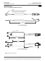
Other Options…
List 40: AC Line Cord Kit, 120VAC, for List 1,
2, 3, 4, 6, 7, 21, 22, 23, 24
List 41: AC Line Cord Kit, 208/240VAC, for
List 1, 2, 3, 4, 6, 7, 21, 22, 23, 24
List 42: Molex Connecor AC Input Option for
List 6, 7
List 43: AC Vertical Feed Assembly
See ACCESSORY
INFORMATION Section
for…
List 46: Molex Connecor AC Input Option for
List 6, 7
List 47: AC Line Cord Kit, 120VAC, for List 11,
12, 13, 14
Distribution Devices
List 48: AC Line Cord Kit, 240VAC, for List 11,
12, 13, 14
Recommended Wire
Sizes, Branch Circuit
Protection, and Lugs
List 50: Blank Module
TXM Extension Cable
List 73: Replacement Ringing Generator for
List 72
Load Shed Card
Ringing Distribution
Module
List 80: Cable, Local Computer Access
AP6C57EA/EB Ring &
Distribution Module
List 81: Cable, MCA Control Bus
List 90: Battery Temperature Probe
List 91, 93: Battery Temperature Probe
List 92: Battery Temperature Probe
Concentrator Module (TXM)
List 94: TXM Interface Cable-10 ft.
List 95: TXM Interface Cable-15 ft.
Page 4 of 105
This document is property of Emerson Network Power, Energy Systems, North America, Inc. and contains confidential and proprietary information owned by Emerson Network Power, Energy
Systems, North America, Inc. Any copying, use, or disclosure of it without the written permission of Emerson Network Power, Energy Systems, North America, Inc. is strictly prohibited.
System Application Guide
Spec. No. 589200300 (Model XP4890)
SAG589200300
Issue AM, September 21, 2009
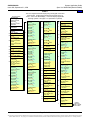
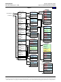
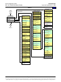
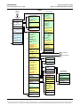
TABLE OF CONTENTS
Ordering Information
System
Overview
Picture
List
Descriptions
Accessory
Descriptions
List of
Parts
Specifications
Physical
Size
Information
Related
Documentation
LXP INTRODUCTION ................................................................................................................................................1
MODEL XP4890 OVERVIEW ....................................................................................................................................1
589200300.............................................................................................................................................................4
TABLE OF CONTENTS.............................................................................................................................................5
ORDERING INFORMATION......................................................................................................................................8
List Options..........................................................................................................................................................8
Accessory Options............................................................................................................................................10
LIST DESCRIPTIONS ..............................................................................................................................................11
List 1: 23” Power and Distribution Shelf with Load Shunt, Dual AC Feed ...................................................11
List 2: 23” Power and Distribution Shelf with Load and Battery Shunts, Dual AC Feed..............................12
List 3: 23” Power and Distribution Shelf with Load and Battery Shunts, Low Voltage Load
Disconnect, Dual AC Feed.............................................................................................................................13
List 4: 23” Power and Distribution Shelf with Load and Battery Shunts, Low Voltage Battery
Disconnect, Dual AC Feed.............................................................................................................................14
List 6: 23” Power and Distribution Shelf with Battery Shunt, Dual AC Feed................................................15
List 7: 23” Power and Distribution Shelf with Battery Shunt, Low Voltage Battery Disconnect, Dual
AC Feed .........................................................................................................................................................16
List 11: 23” Front Access Power and Distribution Shelf with Load Shunt, Dual AC Feed ...........................18
List 12: 23” Front Access Power and Distribution Shelf with Load and Battery Shunts, Dual AC
Feed ...............................................................................................................................................................19
List 13: 23” Front Access Power and Distribution Shelf with Load and Battery Shunts, Low Voltage
Load Disconnect, Dual AC Feed...................................................................................................................20
List 14: 23” Front Access Power and Distribution Shelf with Load and Battery Shunts, Low Voltage
Battery Disconnect, Dual AC Feed ...............................................................................................................21
List 21: 23” Power and Distribution Shelf with Load Shunt, Single AC Feed ..............................................22
List 22: 23” Power and Distribution Shelf with Load and Battery Shunts, Single AC Feed .........................23
List 23: 23” Power and Distribution Shelf with Load and Battery Shunts, Low Voltage Load
Disconnect, Single AC Feed ..........................................................................................................................25
List 24: 23” Power and Distribution Shelf with Load and Battery Shunts, Low Voltage Battery
Disconnect, Single AC Feed ..........................................................................................................................26
List 32: Model LXC300 Meter, Control and Alarm Assembly (MCA) ...........................................................27
List 40: AC Line Cord Kit, 120VAC ...............................................................................................................27
List 41: AC Line Cord Kit, 208/240VAC ........................................................................................................28
List 42: AC Input Molex Connector Option, 120/208/240VAC ......................................................................28
List 43: AC Input Vertical Feed Assembly.....................................................................................................29
List 46: AC Input Molex Connector Option, 120/208/240VAC ......................................................................29
List 47: AC Line Cord Kit, 120VAC ...............................................................................................................29
List 48: AC Line Cord Kit, 240VAC ...............................................................................................................30
List 50: Blank Module....................................................................................................................................30
List 53: 1000 Watt Power Conversion Unit (PCU) ........................................................................................30
List 55: 1500 Watt Power Conversion Unit (PCU) ........................................................................................30
List 56: 1750 Watt Power Conversion Unit (PCU) ........................................................................................31
List 72: Model LXR050 Redundant Ringing Generator Module....................................................................31
List 73: Replacement Ringing Generator......................................................................................................31
Page 5 of 105
This document is property of Emerson Network Power, Energy Systems, North America, Inc. and contains confidential and proprietary information owned by Emerson Network Power, Energy
Systems, North America, Inc. Any copying, use, or disclosure of it without the written permission of Emerson Network Power, Energy Systems, North America, Inc. is strictly prohibited.
SAG589200300
Issue AM, September 21, 2009
List 80:
List 81:
List 90:
List 91:
List 92:
List 93:
List 94:
List 95:
System Application Guide
Spec. No. 589200300 (Model XP4890)
Local Computer Access Cable .........................................................................................................32
RJ-45 MCA Control Bus Cable.........................................................................................................32
Battery Temperature Probe (Analog Output) ...................................................................................32
Battery Temperature Probe (Digital Output).....................................................................................33
Temperature Concentrator Module (TXM) .......................................................................................33
Battery Temperature Probe (Digital Output).....................................................................................34
TXM-MCA Interface Cable ...............................................................................................................34
TXM-MCA Interface Cable ...............................................................................................................34
ACCESSORY DESCRIPTIONS...............................................................................................................................35
Recommended Wire Sizes and Branch Circuit Protection ...........................................................................35
AC Input Wire Sizes, Branch Circuit Protection ............................................................................................35
Distribution (Load) Wire Sizes and Lugs—Bullet Nose Breakers and TPS/TLS Fuseholders ......................38
Load Distribution Wiring—GMT Fuses...........................................................................................................38
Battery Wire Sizes and Lugs—List 1, 2, 3, 4, 21, 22, 23 and 24 Power and Distribution Shelves................40
Battery Wire Sizes and Lugs—List 6 and 7 Power and Distribution Shelves ................................................41
Battery Wire Sizes and Connectors—List 11, 12, 13, and 14 Power and Distribution Shelves ....................41
External Alarm, Reference, and Control Wire Sizes ......................................................................................42
Distribution Devices..........................................................................................................................................43
Bullet Nose Type Circuit Breakers .................................................................................................................43
TPS/TLS-Type Fuses.....................................................................................................................................44
Plug-In Alarm-Type Fuse Distribution Assembly (Part No. 529034) (6) GMT Alarm-Type Fuse
Positions (for List 1, 2, 3, 4 Power and Distribution Shelves) ........................................................................45
Alarm-Type Fuses ..........................................................................................................................................46
Replacement Cables .........................................................................................................................................46
MCA Control Bus Termination Plug ...............................................................................................................46
RJ-45 MCA Control Bus Termination Plug ....................................................................................................46
Bulk Output Cable for List 72 Ringing Generator...........................................................................................47
GMT Distribution Cable for List 6 and 7 .........................................................................................................47
TXM Extension Cable (Part No. 514153) .........................................................................................................47
Load Shed Card (Part No. 528927)...................................................................................................................47
Ringing Distribution Module (Part No. 528608)..............................................................................................48
AP6C57EA/EB Ring & Distribution Module ....................................................................................................48
Field-Replaceable Components.......................................................................................................................50
LIST OF PARTS.......................................................................................................................................................51
SPECIFICATIONS....................................................................................................................................................54
1. System ...........................................................................................................................................................54
1.1 Environmental Ratings .............................................................................................................................54
1.2 Compliance Information ...........................................................................................................................54
1.3 Local Controls and Indicators...................................................................................................................55
2. PCU.................................................................................................................................................................55
2.1 Output Ratings .........................................................................................................................................55
2.2 Input Ratings ............................................................................................................................................57
2.3 Standard Features....................................................................................................................................64
3. MCA ................................................................................................................................................................73
3.1 Standard Features....................................................................................................................................73
3.2 Web Interface ...........................................................................................................................................84
4. List 72 Redundant Ringing Generator System ..........................................................................................85
4.1 Output Ratings .........................................................................................................................................85
4.2 Input Ratings: ...........................................................................................................................................85
4.3 Environmental Ratings .............................................................................................................................85
4.4 Standard Features....................................................................................................................................86
PHYSICAL SIZE INFORMATION ............................................................................................................................88
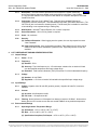
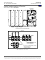
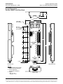
Overall Dimensions – List 1, 2, 3, 4, 21, 22, 23, 24 Power Shelves...............................................................88
Page 6 of 105
This document is property of Emerson Network Power, Energy Systems, North America, Inc. and contains confidential and proprietary information owned by Emerson Network Power, Energy
Systems, North America, Inc. Any copying, use, or disclosure of it without the written permission of Emerson Network Power, Energy Systems, North America, Inc. is strictly prohibited.
System Application Guide
Spec. No. 589200300 (Model XP4890)
SAG589200300
Issue AM, September 21, 2009
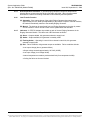
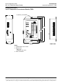
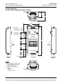
Installer’s Connections Locations and Dimensions – List 1, 2, 3, 4, 21, 22, 23, 24 AC Input,
Alarm, Control & Reference .............................................................................................................................89
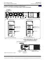
Installer’s Connections Locations and Dimensions – List 1, 2, 3, 4, 21, 22, 23, 24 Distribution...............90
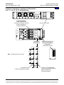
Installer’s Connections Locations and Dimensions – List 1, 2, 3, 4, 21, 22, 23, 24 Battery.......................91
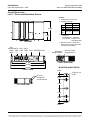
Overall Dimensions – List 6, 7 Power and Distribution Shelves ..................................................................92
Additional Dimensions – List 6, 7 Power and Distribution Shelves When Equipped With List 46...........93
Installer’s Connections Locations and Dimensions – List 6, 7 AC Input, Alarm, Control &
Reference ...........................................................................................................................................................94
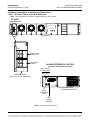
Installer’s Connections Locations and Dimensions – List 6, 7 AC Input When Equipped With
List 46 .................................................................................................................................................................95
Installer’s Connections Locations and Dimensions – List 6, 7 DC Distribution and Battery....................96
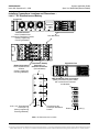
Overall Dimensions – List 11, 12, 13, 14 Power Shelves..............................................................................97
Installer’s Connections Locations and Dimensions – List 11, 12, 13, 14 AC Input, Alarm, Control
& Reference........................................................................................................................................................98
Installer’s Connections Locations and Dimensions – List 11, 12, 13, 14 Distribution and Battery..........99
Overall Dimensions – List 90, 91, 93 Battery Temperature Probes...........................................................100
Overall Dimensions – List 92 Temperature Concentrator Module (TXM) .................................................101
Overall Dimensions – Part No. 528927 Load Shed Card ............................................................................102
Overall Dimensions – Part No. 528608 Ringing Distribution Module .......................................................103
RELATED DOCUMENTATION..............................................................................................................................104
REVISION RECORD ..............................................................................................................................................105
Page 7 of 105
This document is property of Emerson Network Power, Energy Systems, North America, Inc. and contains confidential and proprietary information owned by Emerson Network Power, Energy
Systems, North America, Inc. Any copying, use, or disclosure of it without the written permission of Emerson Network Power, Energy Systems, North America, Inc. is strictly prohibited.
SAG589200300
Issue AM, September 21, 2009
System Application Guide
Spec. No. 589200300 (Model XP4890)
Home
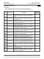
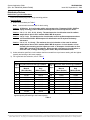
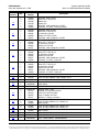
ORDERING INFORMATION
List Options
Order the following by the items Part Number as specified in the following table.
When viewing electronically, click on the List # to jump to the detailed description page.
List
No.
Part Number
1
58920030001
2
58920030002
3
58920030003
4
58920030004
6
58920030006
7
58920030007
11
58920030011
12
58920030012
13
58920030013
14
58920030014
21
58920030021
22
58920030022
23
58920030023
Description
Integrated Power & Distribution Shelf, 23”, up to 114 Amps
(5250W) of power conversion, equipped with Load Shunt, dual
AC feed.
Integrated Power & Distribution Shelf, 23”, up to 114 Amps
(5250W) of power conversion, equipped with Load & Battery
Shunts, dual AC feed.
Integrated Power & Distribution Shelf, 23”, up to 114 Amps
(5250W) of power conversion, equipped with Load & Battery
Shunts & LVLD, dual AC feed.
Integrated Power & Distribution Shelf, 23”, up to 114 Amps
(5250W) of power conversion, equipped with Load & Battery
Shunts & LVBD, dual AC feed.
Integrated Power & Distribution Shelf, 23”, up to 114 Amps
(5250W) of power conversion, equipped with Battery Protective
Device and Battery Shunt, dual AC feed.
Integrated Power & Distribution Shelf, 23”, up to 114 Amps
(5250W) of power conversion, equipped with Battery Protective
Device, Battery Shunt & BLVD, dual AC feed.
23” Integrated Power & Distribution Shelf, All Front Access
Connections, up to 114 Amps (5250W) of power conversion,
equipped with Load Shunt, dual AC feed.
23” Integrated Power & Distribution Shelf, All Front Access
Connections, up to 114 Amps (5250W) of power conversion,
equipped with Load & Battery Shunts, dual AC feed.
23” Integrated Power & Distribution Shelf, All Front Access
Connections, up to 114 Amps (5250W) of power conversion,
equipped with Load & Battery Shunts & LVLD, dual AC feed.
23” Integrated Power & Distribution Shelf, All Front Access
Connections, up to 114 Amps (5250W) of power conversion,
equipped with Load & Battery Shunts & LVBD, dual AC feed.
Integrated Power & Distribution Shelf, 23”, up to 114 Amps
(5250W) of power conversion, equipped with Load Shunt, single
AC feed.
Integrated Power & Distribution Shelf, 23”, up to 114 Amps
(5250W) of power conversion, equipped with Load & Battery
Shunts, single AC feed.
Integrated Power & Distribution Shelf, 23”, up to 114 Amps
(5250W) of power conversion, equipped with Load & Battery
Shunts & LVLD, single AC feed.
Mounting
Positions
(1U = 1-3/4”)
2U
2U
2U
2U
2U
2U
2U
2U
2U
2U
2U
2U
2U
Page 8 of 105
This document is property of Emerson Network Power, Energy Systems, North America, Inc. and contains confidential and proprietary information owned by Emerson Network Power, Energy
Systems, North America, Inc. Any copying, use, or disclosure of it without the written permission of Emerson Network Power, Energy Systems, North America, Inc. is strictly prohibited.
System Application Guide
Spec. No. 589200300 (Model XP4890)
List
No.
Part Number
24
58920030024
32
58920030032
40
58920030040
41
58920030041
42
43
46
58920030042
58920030043
58920030046
47
58920030047
48
58920030048
50
58920030050
53
58920030053
55
58920030055
56
58920030056
72
73
80
81
90
91
92
93
94
95
58920030072
58920030073
58920030080
58920030081
58920030090
58920030091
58920030092
58920030093
58920030094
58920030095
SAG589200300
Issue AM, September 21, 2009
Description
Integrated Power & Distribution Shelf, 23”, up to 114 Amps
(5250W) of power conversion, equipped with Load & Battery
Shunts & LVBD, single AC feed.
LXC300 Meter, Control, Alarm Assembly (MCA), with Ethernet
AC Line Cord Kit, (1) 14.5 ft. cord, 120VAC, NEMA L5-30P
Plugs, for List 1, 2, 3, 4, 21, 22, 23 and 24.
AC Line Cord Kit, (1) 14.5 ft. cord, 208/240VAC, NEMA L6-30P
Plugs, for List 1, 2, 3, 4, 21, 22, 23 and 24.
AC Input Option, Molex connectors on harness, for List 6 & 7.
AC Input Vertical Feed Assembly
AC Input Option, shelf-mounted Molex connectors, for List 6 & 7.
AC Line Cord Kit, (2) 120VAC, NEMA 5-15P Plugs, 6- and 10-ft.
length available, for List 11, 12, 13, and 14 only
AC Line Cord Kit, (2) 240VAC, NEMA 6-20P Plugs, 6- and 10-ft.
length available, for List 11, 12, 13, and 14 only
Blank Module
Model LXP1000 Power Conversion Unit (PCU), 1000W, 48V,
120/208/240VAC
Model LXP1500 Power Conversion Unit (PCU), 1500W, 48V,
120/208/240VAC
Model LXP1750 Power Conversion Unit (PCU), 1750W, 48V,
120/208/240VAC
Redundant Ringing Generator Module, 50VA, In-shelf
Replacement Ringing Generator for List 73
Cable, Local Computer Access
Cable, RJ-45, MCA Control Bus
Battery Temperature Probe, Analog
Battery Temperature Probe, Digital, 25 ft. cord
Temperature Probe Concentrator Module (TXM)
Battery Temperature Probe, digital, 2-1/2 ft. cord
Cable, interface, TXM to MCA, 10 ft. long.
Cable, interface, TXM to MCA, 15 ft. long.
Mounting
Positions
(1U = 1-3/4”)
2U
-----------------------
Page 9 of 105
This document is property of Emerson Network Power, Energy Systems, North America, Inc. and contains confidential and proprietary information owned by Emerson Network Power, Energy
Systems, North America, Inc. Any copying, use, or disclosure of it without the written permission of Emerson Network Power, Energy Systems, North America, Inc. is strictly prohibited.
SAG589200300
Issue AM, September 21, 2009
System Application Guide
Spec. No. 589200300 (Model XP4890)
Home
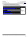
Accessory Options
Order the following by the items Part Number as specified in the following table.
When viewing electronically, click on the link to jump to the detailed description page.
Description
Part Number
Recommended Wire Sizes, Branch Circuit Protection, and Lugs
Distribution Devices
Replacement Cables
See ACCESSORY
DESCRIPTIONS
Section
TXM Extension Cable (Part No. 514153)
Load Shed Card (Part No. 528927)
Ringing Distribution Module (Part No. 528608)
Field-Replaceable Components
Page 10 of 105
This document is property of Emerson Network Power, Energy Systems, North America, Inc. and contains confidential and proprietary information owned by Emerson Network Power, Energy
Systems, North America, Inc. Any copying, use, or disclosure of it without the written permission of Emerson Network Power, Energy Systems, North America, Inc. is strictly prohibited.
System Application Guide
Spec. No. 589200300 (Model XP4890)
SAG589200300
Issue AM, September 21, 2009
Home
LIST DESCRIPTIONS
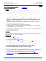
List 1: 23” Power and Distribution Shelf
with Load Shunt, Dual AC Feed
List of Parts
Features
♦
Provides common equipment for one (1) Integrated Power & Distribution Shelf rated for up to 114
Amperes (5250W) of power conversion and up to 100A of distribution.
♦
Provides (4) mounting positions for bullet nose Load Distribution Fuseholders or Circuit Breakers (3 to
100A TPS/TLS-Type Fuses or 1 to 100A Bullet Nose Type Circuit Breakers). Unless otherwise specified,
circuit breakers or fuses will be mounted from top to bottom, starting with the highest capacity and
working to the lowest capacity.
Caution: A circuit breaker or fuse with a rating greater than 75 amperes SHALL HAVE an empty
mounting position between it and any other overcurrent protective device.
Caution: The maximum size circuit breaker or fuse used in ambient temperatures above +50°C
ambient SHALL BE 40 amperes.
♦
Provides ten (10) mounting positions for GMT-type distribution fuses (30A max. total, 1-15A fuses).
♦
Provides one (1) load shunt (total distribution current).
♦
Provides mounting positions for one (1) MCA and up to three (3) PCUs.
♦
Provides two (2) AC input circuits via front-access terminal block connections. Conduit openings are
provided on side panel in front of mounting angle.
♦
Included are two (2) control bus termination plugs. (All control bus ports in the system must be filled, with
either a cable or a termination plug.)
♦
Mounts in a standard 23” relay rack.
Restrictions
Not a direct replacement for earlier versions of List 1. Earlier versions of List 1 provided a single AC feed. To
replace a single-feed version of List 1, order List 21.
Ordering Notes
1) Order one (1) List 32 MCA.
2) Order PCUs per List 53, 55 or 56 as required.
3) Order Ringing Generators per List 72 as required.
4) If AC line cords are required, order two (2) List 40 (120VAC) or two (2) List 41 (208/240VAC) per List 1
Power Shelf.
5) If battery charge temperature compensation is required, order a Battery Temperature Probe as required,
order per List 90. For multiple probes, order One (1) List 92 TXM and List 91 probes as required.
6) For bullet nose distribution positions, order circuit breakers, as required, per Table 5.
7) For bullet nose distribution positions, order fuses, as required, per Table 6.
8) Order one (1) Part No. 117201 fuseholder per fuse ordered in 7) above.
9) Order one (1) Load lug (one-hole, 1/4” bolt clearance hole) and one (1) Load Return lug (two-hole, 1/4”
bolt clearance holes on 5/8” centers) as required for each bullet nose distribution position per Table 2.
10) For GMT alarm type fuse distribution positions, order fuses, as required, per Table 7.
11) Order Battery lugs as required per Battery Wire Sizes and Lugs—List 1, 2, 3, and 4 Power and
Distribution Shelves in the ACCESSORY INFORMATION section.
Page 11 of 105
This document is property of Emerson Network Power, Energy Systems, North America, Inc. and contains confidential and proprietary information owned by Emerson Network Power, Energy
Systems, North America, Inc. Any copying, use, or disclosure of it without the written permission of Emerson Network Power, Energy Systems, North America, Inc. is strictly prohibited.
SAG589200300
Issue AM, September 21, 2009
System Application Guide
Spec. No. 589200300 (Model XP4890)
List of Parts
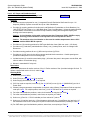
List 2: 23” Power and Distribution Shelf
with Load and Battery Shunts, Dual AC Feed
Features
♦
Provides common equipment for one (1) Integrated Power & Distribution Shelf rated for up to 114
Amperes (5250W) of power conversion and up to 100A of distribution.
♦
Provides (4) mounting positions for bullet nose Load Distribution Fuseholders or Circuit Breakers (3 to
100A TPS/TLS-Type Fuses or 1 to 100A Bullet Nose Type Circuit Breakers). Unless otherwise specified,
circuit breakers or fuses will be mounted from top to bottom, starting with the highest capacity and
working to the lowest capacity.
Caution: A circuit breaker or fuse with a rating greater than 75 amperes SHALL HAVE an empty
mounting position between it and any other overcurrent protective device.
Caution: The maximum size circuit breaker or fuse used in ambient temperatures above +50°C
ambient SHALL BE 40 amperes.
♦
Provides ten (10) mounting positions for GMT-type distribution fuses (30A max. total, 1-15A fuses).
♦
Provides one (1) load shunt (total distribution current) and one (1) battery shunt.
♦
Provides mounting positions for one (1) MCA and up to three (3) PCUs.
♦
Provides two (2) AC input circuits via front-access terminal block connections. Conduit openings are
provided on side panel in front of mounting angle.
♦
Included are two (2) control bus termination plugs. (All control bus ports in the system must be filled, with
either a cable or a termination plug.)
♦
Mounts in a standard 23” relay rack.
Restrictions
Not a direct replacement for earlier versions of List 2. Earlier versions of List 2 provided a single AC feed. To
replace a single-feed version of List 2, order List 22.
Ordering Notes
1) Order one (1) List 32 MCA.
2) Order PCUs per List 53, 55 or 56 as required.
3
3) Order Ringing Generators per List 72 as required.
4) If AC line cords are required, order two (2) List 40 (120VAC) or two (2) List 41 (208/240VAC) per List 2
Power Shelf.
5) If battery charge temperature compensation is required, order a Battery Temperature Probe as required,
order per List 90. For multiple probes, order One (1) List 92 TXM and List 91 probes as required.
6) For bullet nose distribution positions, order circuit breakers, as required, per Table 5.
7) For bullet nose distribution positions, order fuses, as required, per Table 6.
8) Order one (1) Part No. 117201 fuseholder per fuse ordered in 7) above.
9) Order one (1) Load lug (one-hole, 1/4” bolt clearance hole) and one (1) Load Return lug (two-hole, 1/4”
bolt clearance holes on 5/8” centers) as required for each bullet nose distribution position per Table 2.
10) For GMT alarm type fuse distribution positions, order fuses, as required, per Table 7.
11) Order Battery lugs as required per Battery Wire Sizes and Lugs—List 1, 2, 3, and 4 Power and
Distribution Shelves in the ACCESSORY INFORMATION section.
Page 12 of 105
This document is property of Emerson Network Power, Energy Systems, North America, Inc. and contains confidential and proprietary information owned by Emerson Network Power, Energy
Systems, North America, Inc. Any copying, use, or disclosure of it without the written permission of Emerson Network Power, Energy Systems, North America, Inc. is strictly prohibited.
System Application Guide
Spec. No. 589200300 (Model XP4890)
SAG589200300
Issue AM, September 21, 2009
List 3: 23” Power and Distribution Shelf
with Load and Battery Shunts, Low Voltage Load
Disconnect, Dual AC Feed
List of Parts
Features
♦
Provides common equipment for one (1) Integrated Power & Distribution Shelf rated for up to 114
Amperes (5250W) of power conversion and up to 100A of distribution.
♦
Provides (4) mounting positions for bullet nose Load Distribution Fuseholders or Circuit Breakers (3 to
100A TPS/TLS-Type Fuses or 1 to 100A Bullet Nose Type Circuit Breakers). Unless otherwise specified,
circuit breakers or fuses will be mounted from top to bottom, starting with the highest capacity and
working to the lowest capacity.
Caution: A circuit breaker or fuse with a rating greater than 75 amperes SHALL HAVE an empty
mounting position between it and any other overcurrent protective device.
Caution: The maximum size circuit breaker or fuse used in ambient temperatures above +50°C
ambient SHALL BE 40 amperes.
♦
Provides ten (10) mounting positions for GMT-type distribution fuses (30A max. total, 1-15A fuses).
♦
Provides one (1) load shunt (total distribution current), one (1) battery shunt, and Low Voltage Load
Disconnect.
♦
Provides mounting positions for one (1) MCA and up to three (3) PCUs.
♦
Provides two (2) AC input circuits via front-access terminal block connections. Conduit openings are
provided on side panel in front of mounting angle.
♦
Included are two (2) control bus termination plugs. (All control bus ports in the system must be filled, with
either a cable or a termination plug.)
♦
Mounts in a standard 23” relay rack.
Restrictions
Not a direct replacement for earlier versions of List 3. Earlier versions of List 3 provided a single AC feed. To
replace a single-feed version of List 3, order List 23.
Ordering Notes
1) Order one (1) List 32 MCA.
2) Order PCUs per List 53, 55 or 56 as required.
3
3) Order Ringing Generators per List 72 as required.
4) If AC line cords are required, order two (2) List 40 (120VAC) or two (2) List 41 (208/240VAC) per List 3
Power Shelf.
5) If battery charge temperature compensation is required, order a Battery Temperature Probe as required,
order per List 90. For multiple probes, order One (1) List 92 TXM and List 91 probes as required.
6) For bullet nose distribution positions, order circuit breakers, as required, per Table 5.
7) For bullet nose distribution positions, order fuses, as required, per Table 6.
8) Order one (1) Part No. 117201 fuseholder per fuse ordered in 7) above.
9) Order one (1) Load lug (one-hole, 1/4” bolt clearance hole) and one (1) Load Return lug (two-hole, 1/4”
bolt clearance holes on 5/8” centers) as required for each bullet nose distribution position per Table 2.
10) For GMT alarm type fuse distribution positions, order fuses, as required, per Table 7.
Page 13 of 105
This document is property of Emerson Network Power, Energy Systems, North America, Inc. and contains confidential and proprietary information owned by Emerson Network Power, Energy
Systems, North America, Inc. Any copying, use, or disclosure of it without the written permission of Emerson Network Power, Energy Systems, North America, Inc. is strictly prohibited.
SAG589200300
Issue AM, September 21, 2009
System Application Guide
Spec. No. 589200300 (Model XP4890)
11) Order Battery lugs as required per Battery Wire Sizes and Lugs—List 1, 2, 3, and 4 Power and
Distribution Shelves in the ACCESSORY INFORMATION section.
List 4: 23” Power and Distribution Shelf
with Load and Battery Shunts, Low Voltage Battery
Disconnect, Dual AC Feed
List of Parts
Features
♦
Provides common equipment for one (1) Integrated Power & Distribution Shelf rated for up to 114
Amperes (5250W) of power conversion and up to 100A of distribution.
♦
Provides (4) mounting positions for bullet nose Load Distribution Fuseholders or Circuit Breakers (3 to
100A TPS/TLS-Type Fuses or 1 to 100A Bullet Nose Type Circuit Breakers). Unless otherwise specified,
circuit breakers or fuses will be mounted from top to bottom, starting with the highest capacity and
working to the lowest capacity.
Caution: A circuit breaker or fuse with a rating greater than 75 amperes SHALL HAVE an empty
mounting position between it and any other overcurrent protective device.
Caution: The maximum size circuit breaker or fuse used in ambient temperatures above +50°C
ambient SHALL BE 40 amperes.
♦
Provides ten (10) mounting positions for GMT-type distribution fuses (30A max. total, 1-15A fuses).
♦
Provides one (1) load shunt (total distribution current), one (1) battery shunt, and Low Voltage Battery
Disconnect.
♦
Provides mounting positions for one (1) MCA and up to three (3) PCUs.
♦
Provides two (2) AC input circuits via front-access terminal block connections. Conduit openings are
provided on side panel in front of mounting angle.
♦
Included are two (2) control bus termination plugs. (All control bus ports in the system must be filled, with
either a cable or a termination plug.)
♦
Mounts in a standard 23” relay rack.
Restrictions
Not a direct replacement for earlier versions of List 4. Earlier versions of List 4 provided a single AC feed. To
replace a single-feed version of List 4, order List 24.
Ordering Notes
1) Order one (1) List 32 MCA.
2) Order PCUs per List 53, 55 or 56 as required.
3
3) Order Ringing Generators per List 72 as required.
4) If AC line cords are required, order two (2) List 40 (120VAC) or two (2) List 41 (208/240VAC) per List 4
Power Shelf.
5) If battery charge temperature compensation is required, order a Battery Temperature Probe as required,
order per List 90. For multiple probes, order One (1) List 92 TXM and List 91 probes as required.
6) For bullet nose distribution positions, order circuit breakers, as required, per Table 5.
7) For bullet nose distribution positions, order fuses, as required, per Table 6.
8) Order one (1) Part No. 117201 fuseholder per fuse ordered in 7) above.
9) Order one (1) Load lug (one-hole, 1/4” bolt clearance hole) and one (1) Load Return lug (two-hole, 1/4”
bolt clearance holes on 5/8” centers) as required for each bullet nose distribution position per Table 2.
Page 14 of 105
This document is property of Emerson Network Power, Energy Systems, North America, Inc. and contains confidential and proprietary information owned by Emerson Network Power, Energy
Systems, North America, Inc. Any copying, use, or disclosure of it without the written permission of Emerson Network Power, Energy Systems, North America, Inc. is strictly prohibited.
System Application Guide
Spec. No. 589200300 (Model XP4890)
SAG589200300
Issue AM, September 21, 2009
10) For GMT alarm type fuse distribution positions, order fuses, as required, per Table 7.
11) Order Battery lugs as required per Battery Wire Sizes and Lugs—List 1, 2, 3, and 4 Power and
Distribution Shelves in the ACCESSORY INFORMATION section.
List 6: 23” Power and Distribution Shelf
with Battery Shunt, Dual AC Feed
List of Parts
Features
♦
Provides common equipment for one (1) Integrated Power & Distribution Shelf rated for up to 114
Amperes (5250W) of power conversion and 80A of distribution at ambient temperatures of 50°C or less
and 60A at ambient temperatures above 50°C.
♦
Provides (3) mounting positions for bullet nose Load Distribution Fuseholders or Circuit Breakers (3 to
100A TPS/TLS-Type Fuses or 1 to 100A Bullet Nose Type Circuit Breakers). Unless otherwise specified,
circuit breakers or fuses will be mounted from top to bottom, starting with the highest capacity and
working to the lowest capacity.
Caution: A circuit breaker or fuse with a rating greater than 75 amperes SHALL HAVE an empty
mounting position between it and any other overcurrent protective device.
Caution: The maximum size circuit breaker or fuse used in ambient temperatures above +50°C
ambient SHALL BE 50 amperes.
♦
Provides (1) mounting position for bullet nose Battery Disconnect Fuseholder or Circuit Breaker (3 to
100A TPS/TLS-Type Fuse or 1 to 100A Bullet Nose Type Circuit Breaker).
Caution: A circuit breaker with a rating greater than 75 amperes SHALL HAVE an empty mounting
position between it and any other overcurrent protective device. A fuse with a rating
greater than 70 amperes SHALL HAVE an empty mounting position between it and any
other overcurrent protective device.
Caution: The maximum size circuit breaker used in ambient temperatures above +50°C ambient
SHALL BE 75 amperes. The maximum size fuse used in ambient temperatures above
+50°C ambient SHALL BE 70 amperes.
♦
Provides (5) mounting positions for GMT-type distribution fuses (30A max. total, 1-15A fuses).
Caution: The maximum size fuse used in ambient temperatures above +50°C ambient SHALL BE
10 amperes.
♦
Provides five (5) GMT Fuse Distribution Cables, one per fuse position. Each cable is 12’ long, 16 AWG,
terminated on one end with a mating connector that plugs into the shelf GMT fuse connector, and left unterminated at the remaining end for connection to customer loads.
♦
Provides (1) battery shunt.
♦
Provides mounting positions for one (1) MCA and up to three (3) PCUs.
♦
Provides two (2) AC input circuits via front-access terminal block connections. Conduit openings are
provided on side panel in front of mounting angle.
♦
Included are two control bus termination plugs. (All control bus ports in the system must be filled, with
either a cable or a termination plug.)
♦
Mounts in a standard 23” relay rack.
Restrictions
None.
Page 15 of 105
This document is property of Emerson Network Power, Energy Systems, North America, Inc. and contains confidential and proprietary information owned by Emerson Network Power, Energy
Systems, North America, Inc. Any copying, use, or disclosure of it without the written permission of Emerson Network Power, Energy Systems, North America, Inc. is strictly prohibited.
SAG589200300
Issue AM, September 21, 2009
System Application Guide
Spec. No. 589200300 (Model XP4890)
Ordering Notes
1) Order one (1) List 32 MCA.
2) Order PCUs per List 53, 55 or 56 as required.
3
3) Order Ringing Generators per List 72 as required.
4) If AC line cords are required, order two (2) List 40 (120VAC) or two (2) List 41 (208/240VAC) per List 6
Power Shelf.
5) If Molex connector AC input is required, order one (1) List 42 or 46 per List 6 Power Shelf.
6) If battery charge temperature compensation is required, order a Battery Temperature Probe as required,
order per List 90. For multiple probes, order One (1) List 92 TXM and List 91 probes as required.
7) For bullet nose distribution and battery disconnect positions, order circuit breakers, as required, per Table
5. Note: For battery disconnect positions, Electrical Trip (white handle) circuit breakers are not
recommended.
8) For bullet nose distribution and battery disconnect positions, order fuses, as required, per Table 6.
9) Order one (1) Part No. 117201 fuseholder per fuse ordered in 7) above.
10) Order one (1) Load lug (two-hole, No. 10 bolt clearance holes on 5/8” centers) and one (1) Load Return
lug (two-hole, No. 10 bolt clearance holes on 5/8” centers) as required for each bullet nose distribution
position per Table 2.
11) For GMT alarm type fuse distribution positions, order fuses, as required, per Table 7.
12) Order Battery lugs as required per Battery Wire Sizes and Lugs—List 1, 2, 3, 4, 6 and 7 Power and
Distribution Shelves in the ACCESSORY INFORMATION section.
List 7: 23” Power and Distribution Shelf
with Battery Shunt, Low Voltage Battery
Disconnect, Dual AC Feed
List of Parts
Features
♦
Provides common equipment for one (1) Integrated Power & Distribution Shelf rated for up to 114
Amperes (5250W) of power conversion and 80A of distribution at ambient temperatures of 50°C or less
and 60A at ambient temperatures above 50°C.
♦
Provides (3) mounting positions for bullet nose Load Distribution Fuseholders or Circuit Breakers (3 to
100A TPS/TLS-Type Fuses or 1 to 100A Bullet Nose Type Circuit Breakers). Unless otherwise specified,
circuit breakers or fuses will be mounted from top to bottom, starting with the highest capacity and
working to the lowest capacity.
Caution: A circuit breaker or fuse with a rating greater than 75 amperes SHALL HAVE an empty
mounting position between it and any other overcurrent protective device.
Caution: The maximum size circuit breaker or fuse used in ambient temperatures above +50°C
ambient SHALL BE 50 amperes.
♦
Provides (1) mounting position for bullet nose Battery Disconnect Fuseholder or Circuit Breaker (3 to
100A TPS/TLS-Type Fuse or 1 to 100A Bullet Nose Type Circuit Breaker).
Caution: A circuit breaker with a rating greater than 75 amperes SHALL HAVE an empty mounting
position between it and any other overcurrent protective device. A fuse with a rating
greater than 70 amperes SHALL HAVE an empty mounting position between it and any
other overcurrent protective device.
Page 16 of 105
This document is property of Emerson Network Power, Energy Systems, North America, Inc. and contains confidential and proprietary information owned by Emerson Network Power, Energy
Systems, North America, Inc. Any copying, use, or disclosure of it without the written permission of Emerson Network Power, Energy Systems, North America, Inc. is strictly prohibited.
System Application Guide
Spec. No. 589200300 (Model XP4890)
SAG589200300
Issue AM, September 21, 2009
Caution: The maximum size circuit breaker used in ambient temperatures above +50°C ambient
SHALL BE 75 amperes. The maximum size fuse used in ambient temperatures above
+50°C ambient SHALL BE 70 amperes.
♦
Provides (5) mounting positions for GMT-type distribution fuses (30A max. total, 1-15A fuses).
Caution: The maximum size fuse used in ambient temperatures above +50°C ambient SHALL BE
10 amperes.
♦
Provides five (5) GMT Fuse Distribution Cables, one per fuse position. Each cable is 12’ long, 16 AWG,
terminated on one end with a mating connector that plugs into the shelf GMT fuse connector, and left unterminated at the remaining end for connection to customer loads.
♦
Provides one (1) battery shunt.
♦
Provides mounting positions for one (1) MCA and up to three (3) PCUs.
♦
Provides two (2) AC input circuits via front-access terminal block connections. Conduit openings are
provided on side panel in front of mounting angle.
♦
Included are two control bus termination plugs. (All control bus ports in the system must be filled, with
either a cable or a termination plug.)
♦
Mounts in a standard 23” relay rack.
Restrictions
None.
Ordering Notes
1) Order one (1) List 32 MCA.
2) Order PCUs per List 53, 55 or 56 as required.
4
3) Order Ringing Generators per List 72 as required.
4) If AC line cords are required, order two (2) List 40 (120VAC) or two (2) List 41 (208/240VAC) per List 7
Power Shelf.
5) If Molex connector AC input is required, order one (1) List 42 or 46 per List 6 Power Shelf.
6) If battery charge temperature compensation is required, order a Battery Temperature Probe as required,
order per List 90. For multiple probes, order One (1) List 92 TXM and List 91 probes as required.
7) For bullet nose distribution and battery disconnect positions, order circuit breakers, as required, per Table
5. Note: For battery disconnect positions, Electrical Trip (white handle) circuit breakers are not
recommended.
8) For bullet nose distribution and battery disconnect positions, order fuses, as required, per Table 6.
9) Order one (1) Part No. 117201 fuseholder per fuse ordered in 7) above.
10) Order one (1) Load lug (two-hole, No. 10 bolt clearance holes on 5/8” centers) and one (1) Load Return
lug (two-hole, No. 10 bolt clearance holes on 5/8” centers) as required for each bullet nose distribution
position per Table 2.
11) For GMT alarm type fuse distribution positions, order fuses, as required, per Table 7.
12) Order Battery lugs as required per Battery Wire Sizes and Lugs—List 1, 2, 3, 4, 6 and 7 Power and
Distribution Shelves in the ACCESSORY INFORMATION section.
Page 17 of 105
This document is property of Emerson Network Power, Energy Systems, North America, Inc. and contains confidential and proprietary information owned by Emerson Network Power, Energy
Systems, North America, Inc. Any copying, use, or disclosure of it without the written permission of Emerson Network Power, Energy Systems, North America, Inc. is strictly prohibited.
SAG589200300
Issue AM, September 21, 2009
System Application Guide
Spec. No. 589200300 (Model XP4890)
List 11: 23” Front Access Power and Distribution Shelf
with Load Shunt, Dual AC Feed
List of Parts
Features
♦
Provides common equipment for one (1) Integrated Power and Distribution Shelf rated for up to 114A
(5250W) of power conversion, and 100A of distribution at ambient temperatures of 50°C or less and 90A
at ambient temperatures above 50°C.
♦
All installer’s connections are front-access.
♦
Provides (3) mounting positions for bullet nose Load Distribution Fuseholders or Circuit Breakers (3 to
100A TPS/TLS-Type Fuses or 1 to 100A Bullet Nose Type Circuit Breakers). Unless otherwise specified,
circuit breakers or fuses will be mounted from top to bottom, starting with the highest capacity and
working to the lowest capacity.
Caution: A circuit breaker or fuse with a rating greater than 75 amperes SHALL HAVE an empty
mounting position between it and any other circuit breaker or fuse.
Caution: The maximum size circuit breaker or fuse used in ambient temperatures above +50°C
ambient SHALL BE 50 amperes. A circuit breaker or fuse located in the mounting
position adjacent to a 40 ampere or 50 ampere circuit breaker or fuse SHALL BE a
maximum of 30 amperes. Where two 40 ampere or 50 ampere circuit breakers or fuses
are used, an empty mounting space SHALL BE provided between them.
♦
Provides ten (10) mounting positions for GMT-type distribution fuses (30A max. total, 1-15A fuses).
♦
Provides one (1) load shunt (total distribution current).
♦
Provides mounting positions for one (1) MCA and up to three (3) PCUs.
♦
Provides two (2) AC input circuits via terminal block connections. Conduit openings are provided on side
panel in front of mounting angle.
♦
Provides connections for three (3) battery strings via locking-type plugs.
♦
Included are two (2) control bus termination plugs. (All control bus ports in the system must be filled, with
either a cable or a termination plug.)
♦
All installer’s connections are made through the front.
♦
See Physical Size Information for dimensions.
Restrictions
Shelf accommodates max. two (2) PCUs when List 47 is included.
Ordering Notes
1) Order one (1) List 32 MCA.
2) Order PCUs per List 53, 55 or 56 as required.
3) Order Ringing Generators per List 72 as required.
4) If AC line cords are required, order one (1) List 47 (120VAC) or 48 (240VAC) per shelf as required for
voltage and cord length. Note: List 47 120VAC line cords are restricted to powering one (1) PCU each.
Also available are List 40 and 41.
5) If battery charge temperature compensation is required, order a Battery Temperature Probe as required,
order per List 90. For multiple probes, order One (1) List 92 TXM and List 91 probes as required.
6) For bullet nose distribution positions, order circuit breakers, as required, per Table 5.
7) For bullet nose distribution positions, order fuses, as required, per Table 6.
8) Order one (1) Part No. 117201 fuseholder per fuse ordered in 7) above.
Page 18 of 105
This document is property of Emerson Network Power, Energy Systems, North America, Inc. and contains confidential and proprietary information owned by Emerson Network Power, Energy
Systems, North America, Inc. Any copying, use, or disclosure of it without the written permission of Emerson Network Power, Energy Systems, North America, Inc. is strictly prohibited.
System Application Guide
Spec. No. 589200300 (Model XP4890)
SAG589200300
Issue AM, September 21, 2009
9) Order one (1) Load lug (one-hole, 1/4” bolt clearance hole) and one (1) Load Return lug (one-hole, 1/4”
bolt clearance) as required for each bullet nose distribution position per Table 2.
10) For GMT alarm type fuse distribution positions, order fuses, as required, per Table 7.
11) Order Battery connectors as required per Battery Wire Sizes and Connectors—List 11, 12, 13, and 14
Power and Distribution Shelves in the ACCESSORY INFORMATION section.
12) For ringing and DC distribution in imbedded subscriber loop carrier systems (such as SLC-96 or SLC
Series-5), order one (1) AP6C57EA/EB Ring & Distribution Module. (See “Accessory Information”.)
List 12: 23” Front Access Power and Distribution Shelf
with Load and Battery Shunts, Dual AC Feed
List of Parts
Features
♦
Provides common equipment for one (1) Integrated Power and Distribution Shelf rated for up to 114A
(5250W) of power conversion, and 100A of distribution at ambient temperatures of 50°C or less and 90A
at ambient temperatures above 50°C.
♦
All installer’s connections are front-access.
♦
Provides (3) mounting positions for bullet nose Load Distribution Fuseholders or Circuit Breakers (3 to
100A TPS/TLS-Type Fuses or 1 to 100A Bullet Nose Type Circuit Breakers). Unless otherwise specified,
circuit breakers or fuses will be mounted from top to bottom, starting with the highest capacity and
working to the lowest capacity.
Caution: A circuit breaker or fuse with a rating greater than 75 amperes SHALL HAVE an empty
mounting position between it and any other circuit breaker or fuse.
Caution: The maximum size circuit breaker or fuse used in ambient temperatures above +50°C
ambient SHALL BE 50 amperes. A circuit breaker or fuse located in the mounting
position adjacent to a 40 ampere or 50 ampere circuit breaker or fuse SHALL BE a
maximum of 30 amperes. Where two 40 ampere or 50 ampere circuit breakers or fuses
are used, an empty mounting space SHALL BE provided between them.
♦
Provides ten (10) mounting positions for GMT-type distribution fuses (30A max. total, 1-15A fuses).
♦
Provides one (1) load shunt (total distribution current) and one (1) battery shunt.
♦
Provides mounting positions for one (1) MCA and up to three (3) PCUs.
♦
Provides two (2) AC input circuits via terminal block connections. Conduit openings are provided on side
panel in front of mounting angle.
♦
Provides connections for three (3) battery strings via locking-type plugs.
♦
Included are two (2) control bus termination plugs. (All control bus ports in the system must be filled, with
either a cable or a termination plug.)
♦
All installer’s connections are made through the front.
♦
See Physical Size Information for dimensions.
Restrictions
Shelf accommodates max. two (2) PCUs when List 47 is included.
Ordering Notes
1) Order one (1) List 32 MCA.
2) Order PCUs per List 53, 55 or 56 as required.
4
3) Order Ringing Generators per List 72 as required.
Page 19 of 105
This document is property of Emerson Network Power, Energy Systems, North America, Inc. and contains confidential and proprietary information owned by Emerson Network Power, Energy
Systems, North America, Inc. Any copying, use, or disclosure of it without the written permission of Emerson Network Power, Energy Systems, North America, Inc. is strictly prohibited.
SAG589200300
Issue AM, September 21, 2009
System Application Guide
Spec. No. 589200300 (Model XP4890)
4) If AC line cords are required, order one (1) List 47 (120VAC) or 48 (240VAC) per shelf as required for
voltage and cord length. Note: List 47 120VAC line cords are restricted to powering one (1) PCU each.
Also available are List 40 and 41.
5) If battery charge temperature compensation is required, order a Battery Temperature Probe as required,
order per List 90. For multiple probes, order One (1) List 92 TXM and List 91 probes as required.
6) For bullet nose distribution positions, order circuit breakers, as required, per Table 5.
7) For bullet nose distribution positions, order fuses, as required, per Table 6.
8) Order one (1) Part No. 117201 fuseholder per fuse ordered in 7) above.
9) Order one (1) Load lug (one-hole, 1/4” bolt clearance hole) and one (1) Load Return lug (one-hole, 1/4”
bolt clearance) as required for each bullet nose distribution position per Table 2.
10) For GMT alarm type fuse distribution positions, order fuses, as required, per Table 7.
11) Order Battery connectors as required per Battery Wire Sizes and Connectors—List 11, 12, 13, and 14
Power and Distribution Shelves in the ACCESSORY INFORMATION section.
12) For ringing and DC distribution in imbedded subscriber loop carrier systems (such as SLC-96 or SLC
Series-5), order one (1) AP6C57EA/EB Ring & Distribution Module. (See “Accessory Information”.)
List 13: 23” Front Access Power and Distribution Shelf
with Load and Battery Shunts, Low Voltage Load
Disconnect, Dual AC Feed
List of Parts
Features
♦
Provides common equipment for one (1) Integrated Power and Distribution Shelf rated for up to 114A
(5250W) of power conversion, and 100A of distribution at ambient temperatures of 50°C or less and 90A
at ambient temperatures above 50°C.
♦
All installer’s connections are front-access.
♦
Provides (3) mounting positions for bullet nose Load Distribution Fuseholders or Circuit Breakers (3 to
100A TPS/TLS-Type Fuses or 1 to 100A Bullet Nose Type Circuit Breakers). Unless otherwise specified,
circuit breakers or fuses will be mounted from top to bottom, starting with the highest capacity and
working to the lowest capacity.
Caution: A circuit breaker or fuse with a rating greater than 75 amperes SHALL HAVE an empty
mounting position between it and any other circuit breaker or fuse.
Caution: The maximum size circuit breaker or fuse used in ambient temperatures above +50°C
ambient SHALL BE 50 amperes. A circuit breaker or fuse located in the mounting
position adjacent to a 40 ampere or 50 ampere circuit breaker or fuse SHALL BE a
maximum of 30 amperes. Where two 40 ampere or 50 ampere circuit breakers or fuses
are used, an empty mounting space SHALL BE provided between them.
♦
Provides ten (10) mounting positions for GMT-type distribution fuses (30A max. total, 1-15A fuses).
♦
Provides one (1) load shunt (total distribution current), one (1) battery shunt, and Low Voltage Load
Disconnect.
♦
Provides mounting positions for one (1) MCA and up to three (3) PCUs.
♦
Provides two (2) AC input circuits via terminal block connections. Conduit openings are provided on side
panel in front of mounting angle.
♦
Provides connections for three (3) battery strings via locking-type plugs.
♦
Included are two (2) control bus termination plugs. (All control bus ports in the system must be filled, with
either a cable or a termination plug.)
Page 20 of 105
This document is property of Emerson Network Power, Energy Systems, North America, Inc. and contains confidential and proprietary information owned by Emerson Network Power, Energy
Systems, North America, Inc. Any copying, use, or disclosure of it without the written permission of Emerson Network Power, Energy Systems, North America, Inc. is strictly prohibited.
System Application Guide
Spec. No. 589200300 (Model XP4890)
SAG589200300
Issue AM, September 21, 2009
♦
All installer’s connections are made through the front.
♦
See Physical Size Information for dimensions.
Restrictions
Shelf accommodates max. two (2) PCUs when List 47 is included.
Ordering Notes
1) Order one (1) List 32 MCA.
2) Order PCUs per List 53, 55 or 56 as required.
4
3) Order Ringing Generators per List 72 as required.
4) If AC line cords are required, order one (1) List 47 (120VAC) or 48 (240VAC) per shelf as required for
voltage and cord length. Note: List 47 120VAC line cords are restricted to powering one (1) PCU each.
Also available are List 40 and 41.
5) If battery charge temperature compensation is required, order a Battery Temperature Probe as required,
order per List 90. For multiple probes, order One (1) List 92 TXM and List 91 probes as required.
6) For bullet nose distribution positions, order circuit breakers, as required, per Table 5.
7) For bullet nose distribution positions, order fuses, as required, per Table 6.
8) Order one (1) Part No. 117201 fuseholder per fuse ordered in 7) above.
9) Order one (1) Load lug (one-hole, 1/4” bolt clearance hole) and one (1) Load Return lug (one-hole, 1/4”
bolt clearance) as required for each bullet nose distribution position per Table 2.
10) For GMT alarm type fuse distribution positions, order fuses, as required, per Table 7.
11) Order Battery connectors as required per Battery Wire Sizes and Connectors—List 11, 12, 13, and 14
Power and Distribution Shelves in the ACCESSORY INFORMATION section.
12) For ringing and DC distribution in imbedded subscriber loop carrier systems (such as SLC-96 or SLC
Series-5), order one (1) AP6C57EA/EB Ring & Distribution Module. (See “Accessory Information”.)
List 14: 23” Front Access Power and Distribution Shelf
with Load and Battery Shunts, Low Voltage Battery
Disconnect, Dual AC Feed
List of Parts
Features
♦
Provides common equipment for one (1) Integrated Power and Distribution Shelf rated for up to 114A
(5250W) of power conversion, and 100A of distribution at ambient temperatures of 50°C or less and 90A
at ambient temperatures above 50°C.
♦
All installer’s connections are front-access.
♦
Provides (3) mounting positions for bullet nose Load Distribution Fuseholders or Circuit Breakers (3 to
100A TPS/TLS-Type Fuses or 1 to 100A Bullet Nose Type Circuit Breakers). Unless otherwise specified,
circuit breakers or fuses will be mounted from top to bottom, starting with the highest capacity and
working to the lowest capacity.
Caution: A circuit breaker or fuse with a rating greater than 75 amperes SHALL HAVE an empty
mounting position between it and any other circuit breaker or fuse.
Caution: The maximum size circuit breaker or fuse used in ambient temperatures above +50°C
ambient SHALL BE 50 amperes. A circuit breaker or fuse located in the mounting
position adjacent to a 40 ampere or 50 ampere circuit breaker or fuse SHALL BE a
maximum of 30 amperes. Where two 40 ampere or 50 ampere circuit breakers or fuses
are used, an empty mounting space SHALL BE provided between them.
Page 21 of 105
This document is property of Emerson Network Power, Energy Systems, North America, Inc. and contains confidential and proprietary information owned by Emerson Network Power, Energy
Systems, North America, Inc. Any copying, use, or disclosure of it without the written permission of Emerson Network Power, Energy Systems, North America, Inc. is strictly prohibited.
SAG589200300
Issue AM, September 21, 2009
System Application Guide
Spec. No. 589200300 (Model XP4890)
♦
Provides ten (10) mounting positions for GMT-type distribution fuses (30A max. total, 1-15A fuses).
♦
Provides one (1) load shunt (total distribution current), one (1) battery shunt, and Low Voltage Battery
Disconnect.
♦
Provides mounting positions for one (1) MCA and up to three (3) PCUs.
♦
Provides two (2) AC input circuits via terminal block connections. Conduit openings are provided on side
panel in front of mounting angle.
♦
Provides connections for three (3) battery strings via locking-type plugs.
♦
Included are two (2) control bus termination plugs. (All control bus ports in the system must be filled, with
either a cable or a termination plug.)
♦
All installer’s connections are made through the front.
♦
See Physical Size Information for dimensions.
Restrictions
Shelf accommodates max. two (2) PCUs when List 47 is included.
Ordering Notes
1) Order one (1) List 32 MCA.
2) Order PCUs per List 53, 55 or 56 as required.
5
3) Order Ringing Generators per List 72 as required.
4) If AC line cords are required, order one (1) List 47 (120VAC) or 48 (240VAC) per shelf as required for
voltage and cord length. Note: List 47 120VAC line cords are restricted to powering one (1) PCU each.
Also available are List 40 and 41.
5) If battery charge temperature compensation is required, order a Battery Temperature Probe as required,
order per List 90. For multiple probes, order One (1) List 92 TXM and List 91 probes as required.
6) For bullet nose distribution positions, order circuit breakers, as required, per Table 5.
7) For bullet nose distribution positions, order fuses, as required, per Table 6.
8) Order one (1) Part No. 117201 fuseholder per fuse ordered in 7) above.
9) Order one (1) Load lug (one-hole, 1/4” bolt clearance hole) and one (1) Load Return lug (one-hole, 1/4”
bolt clearance) as required for each bullet nose distribution position per Table 2.
10) For GMT alarm type fuse distribution positions, order fuses, as required, per Table 7.
11) Order Battery connectors as required per Battery Wire Sizes and Connectors—List 11, 12, 13, and 14
Power and Distribution Shelves in the ACCESSORY INFORMATION section.
12) For ringing and DC distribution in imbedded subscriber loop carrier systems (such as SLC-96 or SLC
Series-5), order one (1) AP6C57EA/EB Ring & Distribution Module. (See “Accessory Information”.)
List 21: 23” Power and Distribution Shelf
with Load Shunt, Single AC Feed
List of Parts
Features
♦
Provides common equipment for one (1) Integrated Power & Distribution Shelf rated for up to 114
Amperes (5250W) of power conversion and up to 100A of distribution.
♦
Provides (4) mounting positions for bullet nose Load Distribution Fuseholders or Circuit Breakers (3 to
100A TPS/TLS-Type Fuses or 1 to 100A Bullet Nose Type Circuit Breakers). Unless otherwise specified,
Page 22 of 105
This document is property of Emerson Network Power, Energy Systems, North America, Inc. and contains confidential and proprietary information owned by Emerson Network Power, Energy
Systems, North America, Inc. Any copying, use, or disclosure of it without the written permission of Emerson Network Power, Energy Systems, North America, Inc. is strictly prohibited.
System Application Guide
Spec. No. 589200300 (Model XP4890)
SAG589200300
Issue AM, September 21, 2009
circuit breakers or fuses will be mounted from top to bottom, starting with the highest capacity and
working to the lowest capacity.
Caution: A circuit breaker or fuse with a rating greater than 75 amperes SHALL HAVE an empty
mounting position between it and any other overcurrent protective device.
Caution: The maximum size circuit breaker or fuse used in ambient temperatures above +50°C
ambient SHALL BE 40 amperes.
♦
Provides ten (10) mounting positions for GMT-type distribution fuses (30A max. total, 1-15A fuses).
♦
Provides one (1) load shunt (total distribution current).
♦
Provides mounting positions for one (1) MCA and up to three (3) PCUs.
♦
Provides one (1) AC input circuit via front-access terminal block connections. Conduit opening is
provided on side panel in front of mounting angle.
♦
Included are two (2) control bus termination plugs. (All control bus ports in the system must be filled, with
either a cable or a termination plug.)
♦
Mounts in a standard 23” relay rack.
Restrictions
None.
Ordering Notes
1) Direct replacement for earlier versions of List 1. Earlier versions of List 1 provided a single AC feed. To
replace a single-feed version of List 1, order List 21.
2) Order one (1) List 32 MCA.
3) Order PCUs per List 53, 55 or 56 as required.
4) Order Ringing Generators per List 72 as required.
5) If an AC line cord is required, order one (1) List 40 (120VAC) or one (1) List 41 (208/240VAC) per List 21
Power Shelf.
6) If battery charge temperature compensation is required, order a Battery Temperature Probe as required,
order per List 90. For multiple probes, order One (1) List 92 TXM and List 91 probes as required.
7) For bullet nose distribution positions, order circuit breakers, as required, per Table 5.
8) For bullet nose distribution positions, order fuses, as required, per Table 6.
9) Order one (1) Part No. 117201 fuseholder per fuse ordered in 7) above.
10) Order one (1) Load lug (one-hole, 1/4” bolt clearance hole) and one (1) Load Return lug (two-hole, 1/4”
bolt clearance holes on 5/8” centers) as required for each bullet nose distribution position per Table 2.
11) For GMT alarm type fuse distribution positions, order fuses, as required, per Table 7.
12) Order Battery lugs as required per Battery Wire Sizes and Lugs—List 1, 2, 3, and 4 Power and
Distribution Shelves in the ACCESSORY INFORMATION section.
List 22: 23” Power and Distribution Shelf
with Load and Battery Shunts, Single AC Feed
List of Parts
Features
♦
Provides common equipment for one (1) Integrated Power & Distribution Shelf rated for up to 114
Amperes (5250W) of power conversion and up to 100A of distribution.
Page 23 of 105
This document is property of Emerson Network Power, Energy Systems, North America, Inc. and contains confidential and proprietary information owned by Emerson Network Power, Energy
Systems, North America, Inc. Any copying, use, or disclosure of it without the written permission of Emerson Network Power, Energy Systems, North America, Inc. is strictly prohibited.
SAG589200300
Issue AM, September 21, 2009
♦
System Application Guide
Spec. No. 589200300 (Model XP4890)
Provides (4) mounting positions for bullet nose Load Distribution Fuseholders or Circuit Breakers (3 to
100A TPS/TLS-Type Fuses or 1 to 100A Bullet Nose Type Circuit Breakers). Unless otherwise specified,
circuit breakers or fuses will be mounted from top to bottom, starting with the highest capacity and
working to the lowest capacity.
Caution: A circuit breaker or fuse with a rating greater than 75 amperes SHALL HAVE an empty
mounting position between it and any other overcurrent protective device.
Caution: The maximum size circuit breaker or fuse used in ambient temperatures above +50°C
ambient SHALL BE 40 amperes.
♦
Provides ten (10) mounting positions for GMT-type distribution fuses (30A max. total, 1-15A fuses).
♦
Provides one (1) load shunt (total distribution current) and one (1) battery shunt.
♦
Provides mounting positions for one (1) MCA and up to three (3) PCUs.
♦
Provides one (1) AC input circuit via front-access terminal block connections. Conduit opening is
provided on side panel in front of mounting angle.
♦
Included are two (2) control bus termination plugs. (All control bus ports in the system must be filled, with
either a cable or a termination plug.)
♦
Mounts in a standard 23” relay rack.
Restrictions
None.
Ordering Notes
1) Direct replacement for earlier versions of List 2. Earlier versions of List 1 provided a single AC feed. To
replace a single-feed version of List 2, order List 22.
2) Order one (1) List 32 MCA.
3) Order PCUs per List 53, 55 or 56 as required.
5
4) Order Ringing Generators per List 72 as required.
5) If an AC line cord is required, order one (1) List 40 (120VAC) or one (1) List 41 (208/240VAC) per List 22
Power Shelf.
6) If battery charge temperature compensation is required, order a Battery Temperature Probe as required,
order per List 90. For multiple probes, order One (1) List 92 TXM and List 91 probes as required.
7) For bullet nose distribution positions, order circuit breakers, as required, per Table 5.
8) For bullet nose distribution positions, order fuses, as required, per Table 6.
9) Order one (1) Part No. 117201 fuseholder per fuse ordered in 7) above.
10) Order one (1) Load lug (one-hole, 1/4” bolt clearance hole) and one (1) Load Return lug (two-hole, 1/4”
bolt clearance holes on 5/8” centers) as required for each bullet nose distribution position per Table 2.
11) For GMT alarm type fuse distribution positions, order fuses, as required, per Table 7.
12) Order Battery lugs as required per Battery Wire Sizes and Lugs—List 1, 2, 3, and 4 Power and
Distribution Shelves in the ACCESSORY INFORMATION section.
Page 24 of 105
This document is property of Emerson Network Power, Energy Systems, North America, Inc. and contains confidential and proprietary information owned by Emerson Network Power, Energy
Systems, North America, Inc. Any copying, use, or disclosure of it without the written permission of Emerson Network Power, Energy Systems, North America, Inc. is strictly prohibited.
System Application Guide
Spec. No. 589200300 (Model XP4890)
SAG589200300
Issue AM, September 21, 2009
List 23: 23” Power and Distribution Shelf
with Load and Battery Shunts, Low Voltage Load
Disconnect, Single AC Feed
List of Parts
Features
♦
Provides common equipment for one (1) Integrated Power & Distribution Shelf rated for up to 114
Amperes (5250W) of power conversion and up to 100A of distribution.
♦
Provides (4) mounting positions for bullet nose Load Distribution Fuseholders or Circuit Breakers (3 to
100A TPS/TLS-Type Fuses or 1 to 100A Bullet Nose Type Circuit Breakers). Unless otherwise specified,
circuit breakers or fuses will be mounted from top to bottom, starting with the highest capacity and
working to the lowest capacity.
Caution: A circuit breaker or fuse with a rating greater than 75 amperes SHALL HAVE an empty
mounting position between it and any other overcurrent protective device.
Caution: The maximum size circuit breaker or fuse used in ambient temperatures above +50°C
ambient SHALL BE 40 amperes.
♦
Provides ten (10) mounting positions for GMT-type distribution fuses (30A max. total, 1-15A fuses).
♦
Provides one (1) load shunt (total distribution current), one (1) battery shunt, and Low Voltage Load
Disconnect.
♦
Provides mounting positions for one (1) MCA and up to three (3) PCUs.
♦
Provides one (1) AC input circuit via front-access terminal block connections. Conduit opening is
provided on side panel in front of mounting angle.
♦
Included are two (2) control bus termination plugs. (All control bus ports in the system must be filled, with
either a cable or a termination plug.)
♦
Mounts in a standard 23” relay rack.
Restrictions
None.
Ordering Notes
1) Direct replacement for earlier versions of List 3. Earlier versions of List 3 provided a single AC feed. To
replace a single-feed version of List 3, order List 23.
2) Order one (1) List 32 MCA.
3) Order PCUs per List 53, 55 or 56 as required.
5
4) Order Ringing Generators per List 72 as required.
5) If an AC line cord is required, order one (1) List 40 (120VAC) or one (1) List 41 (208/240VAC) per List 23
Power Shelf.
6) If battery charge temperature compensation is required, order a Battery Temperature Probe as required,
order per List 90. For multiple probes, order One (1) List 92 TXM and List 91 probes as required.
7) For bullet nose distribution positions, order circuit breakers, as required, per Table 5.
8) For bullet nose distribution positions, order fuses, as required, per Table 6.
9) Order one (1) Part No. 117201 fuseholder per fuse ordered in 7) above.
10) Order one (1) Load lug (one-hole, 1/4” bolt clearance hole) and one (1) Load Return lug (two-hole, 1/4”
bolt clearance holes on 5/8” centers) as required for each bullet nose distribution position per Table 2.
11) For GMT alarm type fuse distribution positions, order fuses, as required, per Table 7.
Page 25 of 105
This document is property of Emerson Network Power, Energy Systems, North America, Inc. and contains confidential and proprietary information owned by Emerson Network Power, Energy
Systems, North America, Inc. Any copying, use, or disclosure of it without the written permission of Emerson Network Power, Energy Systems, North America, Inc. is strictly prohibited.
SAG589200300
Issue AM, September 21, 2009
System Application Guide
Spec. No. 589200300 (Model XP4890)
12) Order Battery lugs as required per Battery Wire Sizes and Lugs—List 1, 2, 3, and 4 Power and
Distribution Shelves in the ACCESSORY INFORMATION section.
List 24: 23” Power and Distribution Shelf
with Load and Battery Shunts, Low Voltage Battery
Disconnect, Single AC Feed
List of Parts
Features
♦
Provides common equipment for one (1) Integrated Power & Distribution Shelf rated for up to 114
Amperes (5250W) of power conversion and up to 100A of distribution.
♦
Provides (4) mounting positions for bullet nose Load Distribution Fuseholders or Circuit Breakers (3 to
100A TPS/TLS-Type Fuses or 1 to 100A Bullet Nose Type Circuit Breakers). Unless otherwise specified,
circuit breakers or fuses will be mounted from top to bottom, starting with the highest capacity and
working to the lowest capacity.
Caution: A circuit breaker or fuse with a rating greater than 75 amperes SHALL HAVE an empty
mounting position between it and any other overcurrent protective device.
Caution: The maximum size circuit breaker or fuse used in ambient temperatures above +50°C
ambient SHALL BE 40 amperes.
♦
Provides ten (10) mounting positions for GMT-type distribution fuses (30A max. total, 1-15A fuses).
♦
Provides one (1) load shunt (total distribution current), one (1) battery shunt, and Low Voltage Battery
Disconnect.
♦
Provides mounting positions for one (1) MCA and up to three (3) PCUs.
♦
Provides one (1) AC input circuit via front-access terminal block connections. Conduit opening is
provided on side panel in front of mounting angle.
♦
Included are two (2) control bus termination plugs. (All control bus ports in the system must be filled, with
either a cable or a termination plug.)
♦
Mounts in a standard 23” relay rack.
Restrictions
None.
Ordering Notes
1) Direct replacement for earlier versions of List 4. Earlier versions of List 4 provided a single AC feed. To
replace a single-feed version of List 4, order List 24.
2) Order one (1) List 32 MCA.
3) Order PCUs per List 53, 55 or 56 as required.
5
4) Order Ringing Generators per List 72 as required.
5) If an AC line cord is required, order one (1) List 40 (120VAC) or one (1) List 41 (208/240VAC) per List 24
Power Shelf.
6) If battery charge temperature compensation is required, order a Battery Temperature Probe as required,
order per List 90. For multiple probes, order One (1) List 92 TXM and List 91 probes as required.
7) For bullet nose distribution positions, order circuit breakers, as required, per Table 5.
8) For bullet nose distribution positions, order fuses, as required, per Table 6.
9) Order one (1) Part No. 117201 fuseholder per fuse ordered in 7) above.
Page 26 of 105
This document is property of Emerson Network Power, Energy Systems, North America, Inc. and contains confidential and proprietary information owned by Emerson Network Power, Energy
Systems, North America, Inc. Any copying, use, or disclosure of it without the written permission of Emerson Network Power, Energy Systems, North America, Inc. is strictly prohibited.
System Application Guide
Spec. No. 589200300 (Model XP4890)
SAG589200300
Issue AM, September 21, 2009
10) Order one (1) Load lug (one-hole, 1/4” bolt clearance hole) and one (1) Load Return lug (two-hole, 1/4”
bolt clearance holes on 5/8” centers) as required for each bullet nose distribution position per Table 2.
11) For GMT alarm type fuse distribution positions, order fuses, as required, per Table 7.
12) Order Battery lugs as required per Battery Wire Sizes and Lugs—List 1, 2, 3, and 4 Power and
Distribution Shelves in the ACCESSORY INFORMATION section.
List 32: Model LXC300
Meter, Control and Alarm Assembly (MCA)
List of Parts
Features
♦
Consists of one (1) Model LXC300 Meter, Control and Alarm assembly (MCA).
Refer to SPECIFICATIONS for a description of MCA functions.
♦
Mounts in Main Power Shelf. Controls and monitors the following LXP equipment:
Component
Maximum Number*
PCU
17 in up to 3 shelves
Distribution Cabinet (DSM)
4
List 72 Redundant Ringing Generator Module
4 (2 generators ea.)
Load Shed Card, P/N 528927
4
* MCA maximum—quantities may be otherwise restricted in your system.
♦
Standard equipment includes a local user interface as well as a Web Interface for browser-based remote
access via an Ethernet port.
♦
Can be equipped with a Battery Reserve Time Prediction Option. With this software option installed,
the MCA monitors battery voltage during discharge, and uses a Telcordia-defined adaptive algorithm to
predict remaining time before a user-selectable voltage is reached. A “Battery Reserve Low” alarm alerts
user when the predicted remaining time is less than a user-selectable alarm setpoint. The option also
provides a “Battery Health Alarm”, which alerts user when batteries are nearing end-of-life.
♦
Can be equipped with an SNMP Option. With this software option installed, the MCA supports SNMP v2
(Simple Network Management Protocol) interface in a TCP/IP network. Communications to and from the
MCA is accomplished with a MIB (Management Information Base) browser via the MCA Ethernet port.
Ordering Notes
1) Order one (1) List 32 for each List 1, 2, 3, 4, 11, 12, 13, 14, 21, 22, 23, or 24 ordered.
2) Order one (1) List 80 if local PC access to Web Interface is required.
3) Order Battery Reserve Time Prediction Option if required.
4) Order SNMP Option if required.
List 40: AC Line Cord Kit, 120VAC
List of Parts
Features
♦
Provides one (1) 14.5 ft. long AC input cord, equipped with a
NEMA L5-30P, 30A twist-lock plug.
♦
Cord is factory installed.
NEMA 5L-30P
Restrictions
For 120 VAC only. See List 41 for 208/240 VAC applications.
Page 27 of 105
This document is property of Emerson Network Power, Energy Systems, North America, Inc. and contains confidential and proprietary information owned by Emerson Network Power, Energy
Systems, North America, Inc. Any copying, use, or disclosure of it without the written permission of Emerson Network Power, Energy Systems, North America, Inc. is strictly prohibited.
SAG589200300
Issue AM, September 21, 2009
System Application Guide
Spec. No. 589200300 (Model XP4890)
Not available with List 43 AC Input Vertical Feed Assembly.
Not available on List 6 or 7 if equipped with List 42 or 46.
Ordering Notes
1) For 120VAC operation in List 21, 22, 23 or 24 shelves, order one (1) List 40 per Power Shelf.
2) For 120VAC operation in all other List number shelves, order two (2) List 40 per Power Shelf.
List 41: AC Line Cord Kit, 208/240VAC
List of Parts
Features
♦
Provides one (1) 14.5 ft. long AC input cord equipped with a NEMA
L6-30P, 30A twist-lock plug.
♦
Cord is factory installed.
Restrictions
NEMA 6L-30P
For 208/240 VAC only. See List 40 for 120 VAC applications.
Not available with List 43 AC Input Vertical Feed Assembly.
Not available on List 6 or 7 if equipped with List 42 or 46.
Ordering Notes
1) For 208/240VAC operation in List 21, 22, 23 or 24 shelves, order one (1) List 40 per Power Shelf.
2) For 208/240VAC operation in all other List number shelves, order two (2) List 40 per Power Shelf.
List 42: AC Input Molex Connector Option, 120/208/240VAC
List of Parts
Features
♦
Provides two (2) six-inch long AC input cables terminated with Molex connectors.
Cables extend from left-hand side of shelf in front of mounting angle.
♦
One cable feeds PCUs in mounting positions 1 and 3; the other cable feeds mounting
position 2.
♦
For 120/208/240 VAC.
♦
Option is factory installed.
Restrictions
For use on List 6 and 7 shelves only.
Not available with List 43 AC Input Vertical Feed Assembly.
Mating connectors are required.
Ordering Notes
1) For Molex AC input connectors on cables, order one (1) List 42 per List 6 or 7 shelf.
2) For mating AC input connectors, order from Table 1E.
Page 28 of 105
This document is property of Emerson Network Power, Energy Systems, North America, Inc. and contains confidential and proprietary information owned by Emerson Network Power, Energy
Systems, North America, Inc. Any copying, use, or disclosure of it without the written permission of Emerson Network Power, Energy Systems, North America, Inc. is strictly prohibited.
System Application Guide
Spec. No. 589200300 (Model XP4890)
SAG589200300
Issue AM, September 21, 2009
List 43: AC Input Vertical Feed Assembly
List of Parts
Features
♦
Provides top or bottom feed of AC input wiring into the Power Shelf.
Restrictions
Not available with List 40, 41, 47 or 48 AC Line Cord options.
Not available on List 6 or 7 if equipped with List 42 or 46.
Ordering Notes
1) For top or bottom AC feed, order (1) List 43.
List 46: AC Input Molex Connector Option, 120/208/240VAC
List of Parts
Features
♦
Provides two (2) Molex connectors in a housing on the left-hand side of the shelf in front of the mounting
angle.
♦
One connector feeds PCUs in mounting positions 1 and 3; the other connector feeds mounting position 2.
♦
For 120/208/240 VAC.
♦
Option is factory installed.
Restrictions
For use on List 6 and 7 only.
Not available with List 43 AC Input Vertical Feed Assembly.
Mating connectors are required.
Ordering Notes
1) For chassis-mounted Molex AC input connectors, order one (1) List 42 per List 6 or 7 shelf.
2) For mating AC input connectors, order from Table 1E.
List 47: AC Line Cord Kit, 120VAC
List of Parts
Features
♦
Provides two (2) AC input cords, each equipped with a NEMA 515P straight blade plug. Each cord powers one (1) PCU.
♦
Cords are factory installed.
♦
Blank Module is included to cover one (1) unused PCU mounting
position.
NEMA 5-15P
Restrictions
For List 11, 12, 13, and 14 only. Cannot be used with List 1, 2, 3, 4, 6 or 7.
Each cord assembly is rated to power one (1) PCU only (limits shelf to two (2) PCUs total).
For 120 VAC only.
Not available with List 43 AC Input Vertical Feed Assembly.
Page 29 of 105
This document is property of Emerson Network Power, Energy Systems, North America, Inc. and contains confidential and proprietary information owned by Emerson Network Power, Energy
Systems, North America, Inc. Any copying, use, or disclosure of it without the written permission of Emerson Network Power, Energy Systems, North America, Inc. is strictly prohibited.
SAG589200300
Issue AM, September 21, 2009
System Application Guide
Spec. No. 589200300 (Model XP4890)
Ordering Notes
1) For 120VAC operation, order one (1) List 47 per Power Shelf. Order the required length from the
following table.
Length
6 ft.
10 ft.
Part Number
534841
534840
List 48: AC Line Cord Kit, 240VAC
List of Parts
Features
♦
Provides two (2) AC input cords, each equipped with a NEMA 620P straight blade plug.
♦
Cords are factory installed.
Restrictions
For List 11, 12, 13, and 14 only. Cannot be used with List 1, 2, 3, 4, 6
or 7.
NEMA 6-20P
For 240 VAC only.
Not available with List 43 AC Input Vertical Feed Assembly.
Ordering Notes
1) For 240VAC operation, order one (1) List 48 per Power Shelf. Order the required length from the
following table.
Length
6 ft.
10 ft.
Part Number
534843
534842
List 50: Blank Module
List of Parts
Features
♦
Fills one PCU mounting position.
Ordering Notes
1) Order as required.
List 53: 1000 Watt Power Conversion Unit (PCU)
List of Parts
Features
♦
Consists of one (1) Model LXP1000 PCU, Spec. No. 486534800.
Ordering Notes
1) Shelf accepts up to three (3) PCUs.
List 55: 1500 Watt Power Conversion Unit (PCU)
List of Parts
Features
♦
Consists of one (1) Model LXP1500 PCU, Spec. No. 486534204.
Page 30 of 105
This document is property of Emerson Network Power, Energy Systems, North America, Inc. and contains confidential and proprietary information owned by Emerson Network Power, Energy
Systems, North America, Inc. Any copying, use, or disclosure of it without the written permission of Emerson Network Power, Energy Systems, North America, Inc. is strictly prohibited.
System Application Guide
Spec. No. 589200300 (Model XP4890)
SAG589200300
Issue AM, September 21, 2009
Ordering Notes
1) Shelf accepts up to three (3) PCUs.
List 56: 1750 Watt Power Conversion Unit (PCU)
List of Parts
Features
♦
Consists of one (1) Model LXP1750 PCU, Spec. No. 486534600.
Ordering Notes
1) Shelf accepts up to three (3) PCUs
List 72: Model LXR050 Redundant Ringing Generator Module
List of Parts
Features
♦
Provides (1) Model LXR050, Spec. No. 487112200 Redundant Ringing Generator
Module.
♦
Module accepts (2) 50 VA Ringing Generators. Ringing Generators are included.
♦
Operates from the Power Shelf -48VDC output bus to provide a redundant single
frequency ringing system with transfer capability.
♦
Provides up to 50 VA of continuous ringing power.
♦
Uses no rack space. Mounts in one PCU mounting position in the Power Shelf.
♦
Either ringing generator in the module can be selected to supply the load (main generator), with the other
becoming the standby generator. If a failure occurs in the main generator, the ringing load will
automatically transfer to the standby generator. A failed ringing generator can be replaced without
interrupting ringing power to the load.
♦
Controlled and monitored by system’s MCA. MCA supports up to (4) List 72.
Restrictions
Provides bulk ringing output only. Distribution must be external.
MCA interfaces with a maximum of (4) List 72s.
Outputs from multiple List 72s cannot be paralleled.
MCA version 4.0 or newer required for full compatibility.
Ordering Notes
1) Order one (1) List 72 for up to 50 VA of redundant bulk ringing power.
2) For external ringing distribution, order Part No. 528608 Ringing Distribution Module.
List 73: Replacement Ringing Generator
List of Parts
Features
♦
Field replacement for one of the two Part No. 487112100 Ringing Generators that are
provided with List 72.
Ordering Notes
1) Order as a replacement part only. Two Ringing Generators are included with each List 72
ordered.
Page 31 of 105
This document is property of Emerson Network Power, Energy Systems, North America, Inc. and contains confidential and proprietary information owned by Emerson Network Power, Energy
Systems, North America, Inc. Any copying, use, or disclosure of it without the written permission of Emerson Network Power, Energy Systems, North America, Inc. is strictly prohibited.
SAG589200300
Issue AM, September 21, 2009
System Application Guide
Spec. No. 589200300 (Model XP4890)
Home
List 80: Local Computer Access Cable
Features
♦
Category 5 Crossover cable terminated at each end with an RJ-45 plug.
♦
Required for local PC access to the MCA’s Web interface.
♦
Plugs into MCA’s Ethernet connector on the Power Shelf.
♦
Cable identification color is yellow.
Ordering Notes
1) Order the required length from the following table.
Length
Part Number
Length
Part Number
36 inches
4 feet
6 feet
15 feet
514642
514643
514644
524726
25 feet
50 feet
100 feet
514645
514646
514647
List 81: RJ-45 MCA Control Bus Cable
Features
♦
Category 5 Straight Through cable terminated at each end with an RJ-45 plug.
♦
Required for MCA control bus interconnections.
♦
Cable identification color is blue.
Restrictions
Maximum combined MCA control bus cable length must not exceed 125 feet.
Ordering Notes
1) Order the required length from the following table.
Length
Part Number
Length
Part Number
5 inches
6 inches
10 inches
15 inches
524409
509070
528520
509071
2 feet
3 feet
4 feet
25 feet
524410
514639
509900
514640
List 90: Battery Temperature Probe (Analog Output)
List of Parts
Features
♦
Senses battery internal temperature via mounting on negative (–) battery terminal. Mounting hole
provides clearance for 5/16” bolt.
♦
Provides MCA with data required for battery temperature-related functions (temperature-compensated
output voltage, high and low battery temperature alarms).
♦
Plugs into Distribution Sense Module (DSM) (no temperature-compensated output voltage) or into List 92
Temperature Concentrator Module.
Page 32 of 105
This document is property of Emerson Network Power, Energy Systems, North America, Inc. and contains confidential and proprietary information owned by Emerson Network Power, Energy
Systems, North America, Inc. Any copying, use, or disclosure of it without the written permission of Emerson Network Power, Energy Systems, North America, Inc. is strictly prohibited.
System Application Guide
Spec. No. 589200300 (Model XP4890)
SAG589200300
Issue AM, September 21, 2009
Home
♦
15 ft. long cable
♦
See Physical Size Information for probe dimensions.
Restrictions
Not for connection to MCA digital probe jack J3. For single-probe applications, order List 91 or List 93.
Ordering Notes
1) Order up to eight (8) List 90 per List 92 ordered.
List 91: Battery Temperature Probe (Digital Output)
List of Parts
Features
♦
Mounts near the battery to sense battery ambient temperature. Plugs into J3 on the MCA.
♦
Provides MCA with data required for battery temperature-related functions (temperature-compensated
output voltage, high and low battery temperature alarms).
♦
25 ft. long cable
♦
Same as List 93 except for cable length.
♦
See Physical Size Information for probe dimensions.
Restrictions
For use in single-probe applications only. Cannot be used with a List 92 (TXM).
applications with a TXM, order List 90 probes.
For multiple-probe
Ordering Notes
1) Order one (1) List 91 or List 93 per system.
List 92: Temperature Concentrator Module (TXM)
List of Parts
Features
♦
Provides the system MCA with a means of monitoring up to eight (8) List 90 battery
temperature probes. Plugs into J3 on the MCA.
♦
System MCA can be set to compensate on the hottest probe, the average
temperature of all connected probes, or the lowest numbered probe connected.
♦
Mounts externally.
♦
Includes 25 ft. cable for interface to MCA connector J3.
♦
See Physical Size Information for TXM dimensions.
♦
See TXM Installation and User Instructions (Section 5940) for complete specifications.
Restrictions
Requires List 90 temperature probes. Cannot be used with List 91 temperature probes.
Ordering Notes
1) Order one (1) List 92 per system.
2) Order up to eight (8) List 90 analog probes as required.
3) For a shorter interface cable, also order List 94 (10 ft.) or 95 (15 ft.).
Page 33 of 105
This document is property of Emerson Network Power, Energy Systems, North America, Inc. and contains confidential and proprietary information owned by Emerson Network Power, Energy
Systems, North America, Inc. Any copying, use, or disclosure of it without the written permission of Emerson Network Power, Energy Systems, North America, Inc. is strictly prohibited.
SAG589200300
Issue AM, September 21, 2009
System Application Guide
Spec. No. 589200300 (Model XP4890)
Home
List 93: Battery Temperature Probe (Digital Output)
List of Parts
Features
♦
Mounts near the battery to sense battery ambient temperature. Plugs into J3 on the MCA.
♦
Provides MCA with data required for battery temperature-related functions (temperature-compensated
output voltage, high and low battery temperature alarms).
♦
2-1/2 ft. long cable.
♦
Same as List 91 except for cable length.
♦
See Physical Size Information for probe dimensions.
Restrictions
For use in single-probe applications only. Cannot be used with a List 92 (TXM).
applications with a TXM, order List 90 probes.
For multiple-probe
Ordering Notes
1) Order one (1) List 93 or List 91 per system.
List 94: TXM-MCA Interface Cable
Features
List of Parts
♦
Cable, interface, connects between the output connector on the TXM and MCA connector J3.
♦
10 ft. long
♦
Can be used in place of the 25 ft. interface cable provided with the List 92 TXM when a shorter cable is
needed.
List 95: TXM-MCA Interface Cable
List of Parts
Features
♦
Cable, interface, connects between the output connector on the TXM and MCA connector J3.
♦
15 ft. long
♦
Can be used in place of the 25 ft. interface cable provided with the List 92 TXM when a shorter cable is
needed.
Page 34 of 105
This document is property of Emerson Network Power, Energy Systems, North America, Inc. and contains confidential and proprietary information owned by Emerson Network Power, Energy
Systems, North America, Inc. Any copying, use, or disclosure of it without the written permission of Emerson Network Power, Energy Systems, North America, Inc. is strictly prohibited.
System Application Guide
Spec. No. 589200300 (Model XP4890)
SAG589200300
Issue AM, September 21, 2009
Home
ACCESSORY DESCRIPTIONS
Recommended Wire Sizes and Branch Circuit Protection
AC Input Wire Sizes, Branch Circuit Protection
Features
♦
Screw-compression type terminals are provided for connection of AC input wiring. These terminals are
accessed through the front of the Power Shelf.
♦
A threaded stud (8-32) is provided for installation of frame ground wiring. The stud is accessed through
the front of the Power Shelf.
Ordering Notes
1) For Lists 1, 2, 3, 4, 6, 7, 11, 12, 13, and 14, refer to Tables 1A (120VAC) and 1B (208/240VAC) for
recommended wire sizes and branch circuit protection.
2) For Lists 21, 22, 23, and 24, refer to Tables 1C (120VAC) and 1D (208/240VAC) for recommended wire
sizes and branch circuit protection.
3) Notes referenced in tables are found after Table 1E.
1, 2, 3, 4, 6, 7, 11, 12, 13, 14 120 VAC Input (Two AC Input Circuits)
Ambient
Operating
Temperature
(1)
Feed
Recm
Branch
Circuit
Protection
(Amperes)
Line Terminals (6)
Capacity
Type
Recm
Torque
(2, 5)
30°C
40°C
50°C
65°C
#1
20
#2
20
#1
20
#2
20
#1
20
#2
20
#1
20
#2
20
20 to 6
AWG
Screw
Clamp
10.62
to
13.30
in-lbs
Line
Ground (3, 6)
Recm
90°C
Wire Size
Recm 90°C
Wire Size (4)
(1)
12 AWG
12 AWG
10 AWG
Table 1A
Recommended AC Input Branch Circuit Protection and Wire Size Selection
120 VAC Input, Two AC Input Circuits
Page 35 of 105
This document is property of Emerson Network Power, Energy Systems, North America, Inc. and contains confidential and proprietary information owned by Emerson Network Power, Energy
Systems, North America, Inc. Any copying, use, or disclosure of it without the written permission of Emerson Network Power, Energy Systems, North America, Inc. is strictly prohibited.
SAG589200300
Issue AM, September 21, 2009
System Application Guide
Spec. No. 589200300 (Model XP4890)
1, 2, 3, 4, 6, 7, 11, 12, 13, 14 208/240 VAC Input (Two AC Input Circuits)
Ambient
Operating
Temperature
(1)
Recm
Branch
Circuit
Protection
(Amperes)
Feed
Line Terminals (6)
Capacity
Type
Recm
Torque
Line
Ground (3, 6)
Recm
90°C
Wire Size
Recm 90°C
Wire Size (4)
(1)
(2)
30°C
40°C
50°C
65°C
#1
25
#2
25
#1
25
#2
25
#1
25
#2
25
#1
25
#2
25
20 to 6
AWG
Screw
Clamp
10.62
to
13.30
in-lbs
10AWG
10 AWG
8 AWG
Table 1B
Recommended AC Input Branch Circuit Protection and Wire Size Selection
208/240 VAC Input, Two AC Input Circuits
List 21, 22, 23, 24, 120/240 VAC Input (One AC Input Circuit)
Ambient
Operating
Temperature
(1)
Recm
Branch
Circuit
Protection
(Amperes)
Line Terminals
Line
Ground (3)
Recm 90°C
Wire Size (4)
Capacity
Type
Recm
Torque
Recm 90°C
Wire Size (1)
Screw
Clamp
10.62
to
13.30
in-lbs
10 AWG
20 to 6
AWG
(2)
30°C
30
40°C
30
50°C
30
65°C
30
10 AWG
8 AWG
Table 1C
Recommended AC Input Branch Circuit Protection and Wire Size Selection
List 21, 22, 23, 24, 208 VAC, One AC Input Circuit
Page 36 of 105
This document is property of Emerson Network Power, Energy Systems, North America, Inc. and contains confidential and proprietary information owned by Emerson Network Power, Energy
Systems, North America, Inc. Any copying, use, or disclosure of it without the written permission of Emerson Network Power, Energy Systems, North America, Inc. is strictly prohibited.
System Application Guide
Spec. No. 589200300 (Model XP4890)
SAG589200300
Issue AM, September 21, 2009
List 21, 22, 23, 24, 208 VAC Input (One AC Input Circuit)
Ambient
Operating
Temperature
(1)
Recm
Branch
Circuit
Protection
(Amperes)
Line Terminals
Line
Ground (3)
Recm 90°C
Wire Size (4)
Capacity
Type
Recm
Torque
Recm 90°C
Wire Size (1)
Screw
Clamp
10.62
to
13.30
in-lbs
8 AWG
20 to 6
AWG
(2)
30°C
35
40°C
35
50°C
35
65°C
35
10 AWG
6 AWG
Table 1D
Recommended AC Input Branch Circuit Protection and Wire Size Selection
List 21, 22, 23, 24, 208 VAC, One AC Input Circuit
Contact (7)
Vendor
Housing
Wire Capacity
Molex
Emerson Network Power
Molex
Emerson Network Power
0428160312
133302
0428160312
133302
10-12 AWG
8 AWG
Part No.
42815-0012
-42815-0032
133301
Hand Crimp Tool
(Molex Part No.)
63811-1600
63811-1500
Table 1E
List 42 and 46 Mating Connectors (6)
Notes for Tables 1A, 1B, 1C, 1D and 1E
1
Wire sizes are based on recommendations of the American National Standards Institute (ANSI) approved
National Fire Protection Association's (NFPA) National Electrical Code (NEC). Table 310-16 for copper
wire at 90°C conductor temperature, operating in ambients of 30°C, 40°C, 50°C and 65°C was used. For
other operating ambient temperatures, refer to the NEC. For operation in countries where the NEC is not
recognized, follow applicable codes.
2
The AC input branch circuit protective device should be of the time-delay or high inrush type.
3
Equipment grounding conductors must be provided with the AC input conductors supplied to the shelf.
Frame ground terminals must be connected to earth ground, not power system neutral. A ring lug must be
provided.
4
Equipment grounding conductor size is based on recommendations of the NEC Table 250-122 for copper
wire. If aluminum or copper clad aluminum grounding conductor is used, refer to Table 250-122 for
increased conductor size. For operation in countries where the NEC is not recognized, follow applicable
codes.
Page 37 of 105
This document is property of Emerson Network Power, Energy Systems, North America, Inc. and contains confidential and proprietary information owned by Emerson Network Power, Energy
Systems, North America, Inc. Any copying, use, or disclosure of it without the written permission of Emerson Network Power, Energy Systems, North America, Inc. is strictly prohibited.
SAG589200300
Issue AM, September 21, 2009
System Application Guide
Spec. No. 589200300 (Model XP4890)
Home
5
When List 11, 12, 13, or 14 is ordered with List 47 AC cords (120VAC only, restricted to 1 PCU
per cord) recommended branch circuit protection is 15 amperes.
6
When List 6 or 7 is equipped with List 42 or 46, refer to Tables 1A (120VAC) and 1B (208/240VAC) for
recommended wire sizes and branch circuit protection. Refer to Table 1E for mating connector information.
Contacts should be crimped to the specifications given in the manufacturer’s instructions furnished with the
crimp tool or connector.
7
Distribution (Load) Wire Sizes and Lugs—Bullet Nose Breakers and TPS/TLS Fuseholders
Features
♦
The installer connects lug-terminated load and return conductors to the distribution device mounting
positions and the ground busbar. Refer to the following table for the lug mounting provisions of the
available shelves.
Shelf List No.
Each Load Connection
1, 2, 3, 4,
21, 22, 23, 24
(1) 1/4-20 threaded hole
6, 7
(2) 10-32 threaded holes, 5/8” centers
11, 12, 13, 14
(1) 1/4-20 threaded hole
Each Return Connection
(Ground Busbar)
(1) 1/4-20 x 1/2" threaded stud &
(1) alignment pin, 5/8” centers
(1) 10-32 x 1/2” threaded stud &
(1) alignment pin, 5/8” centers
(1) 1/4-20 x 1/2" threaded stud
♦
Maximum size of wire to be connected to a single fuseholder or circuit breaker position is 2 AWG.
♦
For lug mounting hole size and spacing dimensions, refer to the illustrations provided in the Physical Size
Information section.
Restrictions
All lugs for customer connections must be ordered separately.
Ordering Notes
1) The rating of the distribution device determines the wire size requirements. For wire size and lug
selection, refer to Table 2.
2) For other available lugs and hardware, refer to drawings 031110100 through 031110300.
Load Distribution Wiring—GMT Fuses
Features
♦
List 1, 2, 3, 4, 11, 12, 13, 14, 21, 22, 23, 24: Screw-compression type terminals are provided for
connection of Load and Load Return conductors to the GMT alarm type distribution fuse positions.
Terminals accept 14 AWG max.
♦
List 6, 7: Latching type connectors are provided for connection of Load and Load Return conductors to
the GMT alarm type distribution fuse positions. Mating cables, 12 ft. long, 16 AWG are furnished.
Restrictions
None.
Ordering Notes
1) The rating of the distribution device determines the wire size requirements. For wire size, refer to Table
2.
2) List 6, 7 only: Order one (1) Part No. 535206 load cable for each GMT fuse distribution position.
Page 38 of 105
This document is property of Emerson Network Power, Energy Systems, North America, Inc. and contains confidential and proprietary information owned by Emerson Network Power, Energy
Systems, North America, Inc. Any copying, use, or disclosure of it without the written permission of Emerson Network Power, Energy Systems, North America, Inc. is strictly prohibited.
System Application Guide
Spec. No. 589200300 (Model XP4890)
SAG589200300
Issue AM, September 21, 2009
Home
Recm 90°C Wire Size (1)
Fuse/Circuit
Breaker
Amperage
14 AWG
1, 3, 5,
6, 10A
37 (3, 4, 5)
58 (3, 4, 5)
93 (3, 4, 5)
148 (3, 4, 5)
15A
24 (3, 4)
39 (3, 4, 5)
62 (3, 4, 5)
20A
--
29 (3, 4)
25A
--
30A
12 AWG
10 AWG
8 AWG
6 AWG
4 AWG
2 AWG
236 (3, 4, 5)
376 (3, 4, 5)
597 (3, 4, 5)
99 (3, 4, 5)
157 (3, 4, 5)
250 (3, 4, 5)
398 (3, 4, 5)
46 (3, 4, 5)
74 (3, 4, 5)
118 (3, 4, 5)
188 (3, 4, 5)
298 (3, 4, 5)
--
37 (3, 4,)
59 (3, 4, 5)
94 (3, 4, 5)
150 (3, 4, 5)
239 (3, 4, 5)
--
--
31 (3, 4)
49 (3, 4, 5)
78 (3, 4, 5)
125 (3, 4, 5)
199 (3, 4, 5)
35A
--
--
--
42 (3, 4)
67 (3, 4, 5)
107 (3, 4, 5)
170 (3, 4, 5)
40A
--
--
--
37 (3, 4)
59 (3, 4, 5)
94 (3, 4, 5)
149 (3, 4, 5)
45A
--
--
--
33 (3, 4)
52 (3, 4)
83 (3, 4)
132 (3, 4)
50A
--
--
--
29 (3)
47 (3, 4,)
75 (3, 4)
119 (3, 4)
60A
--
--
--
--
39 (3, 4)
62 (3, 4)
99 (3, 4)
70A
--
--
--
--
--
53 (3, 4)
85 (3, 4)
75A
--
--
--
--
--
50 (3, 4)
79 (3, 4)
80A
--
--
--
--
--
47 (3)
74 (3, 4)
90A
--
--
--
--
--
--
66 (3, 4)
100A
--
--
--
--
--
--
59 (3, 4)
Loop Length (feet) (2)
Recommended Crimp Lug (6, 7)
1-Hole,
1/4" bolt
clearance
245312200
245312400
245312400
245350400
245350600
245350700
245350800
2-hole,
1/4" bolt
clearance
245342300
245342300
245342300
245390200
245346700
245346800
245346900
245346600
245346500
--
--
2-hole,
No. 10 bolt
clearance
245390100
Table 2
Recommended Distribution Wire Size and Lug Selection (Load and Load Return)
Notes for Tables 2:
Wire sizes are based on recommendations of the American National Standards Institute (ANSI) approved
National Fire Protection Association's (NFPA) National Electrical Code (NEC). Table 310-16 for wire rated
at 90°C conductor temperature operating in ambient temperatures of 40°C, 50°C, and 65°C was used. For
other operating ambient temperatures, refer to the NEC. For operation in countries where the NEC is not
recognized, follow applicable codes.
2
Recommended wire sizes are sufficient to restrict voltage drop to 1.0 volt or less at listed branch current for
the loop lengths shown. Loop length is the sum of the lengths of the positive and negative leads.
1
Page 39 of 105
This document is property of Emerson Network Power, Energy Systems, North America, Inc. and contains confidential and proprietary information owned by Emerson Network Power, Energy
Systems, North America, Inc. Any copying, use, or disclosure of it without the written permission of Emerson Network Power, Energy Systems, North America, Inc. is strictly prohibited.
SAG589200300
Issue AM, September 21, 2009
System Application Guide
Spec. No. 589200300 (Model XP4890)
Home
Wire Size / Loop Length Combination Calculated using 40°C Ambient Operating Temperature.
Wire Size / Loop Length Combination Calculated using 50°C Ambient Operating Temperature.
Wire Size / Loop Length Combination Calculated using 65°C Ambient Operating Temperature.
One-hole lugs are 1/4" bolt clearance. Two-hole lugs are 1/4" or No. 10, as shown, bolt clearance, on 5/8"
centers. Refer to drawing 031110100 for lug crimping information.
Use 1-hole lugs for Load connections on List 1, 2, 3, 4, 11, 12, 13 and 14. Use 2-hole lugs for Load
connections on List 6 and 7. Use 1-hole lugs for Load Return connections on List 11, 12, 13 and 14. Use
2-hole lugs for Load Return connections on List 1, 2, 3, 4, 6 and 7.
3
4
5
6
7
Battery Wire Sizes and Lugs—List 1, 2, 3, 4, 21, 22, 23 and 24 Power and Distribution Shelves
Features
♦
The installer connects lug-terminated battery conductors to the terminals provided. Captive nuts, (1/4-20
on 5/8" centers) are provided for installation of customer-furnished two-hole lugs. These terminals are
accessed through the cabinet top or rear panel.
♦
For lug mounting hole size and spacing dimensions, refer to the illustration provided in the Physical Size
Information section.
Restrictions
All lugs for customer connections must be ordered separately.
Ordering Notes
1) Battery wire size varies depending on load, therefore no specific information is provided for wire size.
Refer to Table 5 for recommended wire sizes and lugs at rated maximum total distribution load (100
amperes). When making connections, observe correct polarity.
2) For other available lugs and hardware, refer to drawings 031110100 through 031110300.
Maximum
Current
(Amps)
Loop
Loop
Ambient
Recm 90°C
Length (Ft)
Length (Ft)
Operating
Wire Size (1)
(1)
(2)
(2)
0.25 Volt Drop
1.0 Volt Drop
Temperature
40°C
100
50°C
65°C
59
119
59
119
75
112
14
29
14
29
18
28
(1) 2 AWG
(2) 2 AWG
(1) 2 AWG
(2) 2 AWG
(2) 4 AWG
(3) 4 AWG
Recommended
Crimp Lug (3)
(1) 245346900
(2) 245346900
(1) 245346900
(2) 245346900
(2) 245346800
(3) 245346800
Table 3A
Recommended Battery Wire Size and Lug Selection
Notes for Tables 3:
1
Wire sizes are based on recommendations of the American National Standards Institute (ANSI) approved
National Fire Protection Association's (NFPA) National Electrical Code (NEC). Table 310-16 for wire
rated at 90°C conductor temperature operating in ambient temperatures of 40°C, 50°C and 65°C was
used. For other operating ambient temperatures, refer to the NEC. For operation in countries where the
NEC is not recognized, follow applicable codes.
Page 40 of 105
This document is property of Emerson Network Power, Energy Systems, North America, Inc. and contains confidential and proprietary information owned by Emerson Network Power, Energy
Systems, North America, Inc. Any copying, use, or disclosure of it without the written permission of Emerson Network Power, Energy Systems, North America, Inc. is strictly prohibited.
System Application Guide
Spec. No. 589200300 (Model XP4890)
SAG589200300
Issue AM, September 21, 2009
2
Recommended wire sizes are sufficient to restrict voltage drop to the voltage shown in the
column heading, or less, at rated full load output current of the shelf for the loop lengths shown
in this column. Loop length is the sum of the lengths of the positive and negative leads.
3
Two-hole lug, 1/4" bolt clearance hole, 5/8" centers. Refer to drawing 031110100 for lug crimping
information.
Home
Battery Wire Sizes and Lugs—List 6 and 7 Power and Distribution Shelves
Features
♦
The installer connects lug-terminated battery conductors to the disconnect device mounting position and
the ground busbar. The disconnect device mounting position provides (2) 10-32 threaded holes on 5/8”
centers for installation of a customer-furnished two-hole lug. The ground busbar provides (1) 10-32 x 1/2”
threaded stud and (1) alignment pin on 5/8” centers for installation of a customer-furnished two-hole lug.
♦
Maximum size of wire to be connected is 2 AWG.
♦
For lug mounting hole size and spacing dimensions, refer to the illustration provided in the Physical Size
Information section.
Restrictions
All lugs for customer connections must be ordered separately.
Ordering Notes
1) The rating of the disconnect device determines the wire size requirements. For wire size and lug
selection, refer to Table 2.
2) For other available lugs and hardware, refer to drawings 031110100 through 031110300.
Battery Wire Sizes and Connectors—List 11, 12, 13, and 14 Power and Distribution Shelves
Features
♦
Battery connections are made to locking-type plugs. Connections are provided for three (3) battery
strings. These connections are accessed through the front of the cabinet.
Restrictions
Maximum wire size is 6 AWG.
Mating plugs are not provided with the shelf, and must be ordered separately.
Ordering Notes
1) Battery wire size varies depending on load, therefore no specific information is provided for selecting a
wire size. Refer to Table 3B for recommended wire sizes and connectors at rated maximum total
distribution load (100A at or below 50°C ambient, 90A above 50°C ambient). Current is shown evenly
distributed between two battery strings (N+1 redundancy).
Page 41 of 105
This document is property of Emerson Network Power, Energy Systems, North America, Inc. and contains confidential and proprietary information owned by Emerson Network Power, Energy
Systems, North America, Inc. Any copying, use, or disclosure of it without the written permission of Emerson Network Power, Energy Systems, North America, Inc. is strictly prohibited.
SAG589200300
Issue AM, September 21, 2009
System Application Guide
Spec. No. 589200300 (Model XP4890)
Home
Current per Ambient
Housing with 75 Amp
Recm
Loop
Loop
Battery
Contact (3)
Operating Length (Ft) Length (Ft) 90°C
String
1.0 Volt
0.25 Volt
TemperWire Emerson Network
Anderson
(Amps)
Drop (2)
Drop (2)
ature (1)
Size (1) Power Part No.
Part No.
50
45
40°C
50°C
65°C
47
47
52
11
11
13
6 AWG
247108670 (Red) 1300G3 (Red)
6 AWG
247108671 (Black) 1300G4 (Black)
6 AWG
Table 3B
Recommended Battery Wire Size and Lug Selection—
List 11, 12, 13, and 14 Power and Distribution Shelves
Notes for Tables 3B:
1
Wire sizes are based on recommendations of the American National Standards Institute (ANSI) approved
National Fire Protection Association's (NFPA) National Electrical Code (NEC). Table 310-16 for wire
rated at 90°C conductor temperature operating in ambient temperatures of 40°C, 50°C and 65°C was
used. For other operating ambient temperatures, refer to the NEC. For operation in countries where the
NEC is not recognized, follow applicable codes.
2
Recommended wire sizes are sufficient to restrict voltage drop to the voltage shown in the column
heading, or less, at the current shown in the “Current per Battery String” column for the loop lengths
shown in this column. Loop length is the sum of the lengths of the positive and negative leads.
3
Use hand crimping tool, Anderson Part No. 1309G4. Contacts should be crimped to the specifications
given in the manufacturer’s instructions furnished with the crimp tool or connector.
External Alarm, Reference, and Control Wire Sizes
Features
♦
External Alarm, Reference, and Control connections are made to TB1 on the MCA.
Terminals
Capacity
Type
28 to 16
AWG
Screw Clamp
Recm
Wire Size
22 AWG for Loop Lengths Up to 200 ft.
18-20 AWG for Loop Lengths Over 200 ft.
Table 4
Recommended Alarm, Reference, and Control Wire Size
(TB1 and TB2 on MCA)
Page 42 of 105
This document is property of Emerson Network Power, Energy Systems, North America, Inc. and contains confidential and proprietary information owned by Emerson Network Power, Energy
Systems, North America, Inc. Any copying, use, or disclosure of it without the written permission of Emerson Network Power, Energy Systems, North America, Inc. is strictly prohibited.
System Application Guide
Spec. No. 589200300 (Model XP4890)
SAG589200300
Issue AM, September 21, 2009
Home
Distribution Devices
Bullet Nose Type Circuit Breakers
Each circuit breaker plugs into a single mounting position.
Ordering Notes
1) Order circuit breakers per Table 5.
Note:
Load should not exceed 80% of device rating.
Caution: All Shelves: A circuit breaker with a rating greater than 75 amperes SHALL HAVE an
empty mounting position between it and any other overcurrent protective device.
Caution: List 1, 2, 3, 4, 21, 22, 23, 24 only: The maximum size circuit breaker used in ambient
temperatures above +50°C ambient SHALL BE 40 amperes.
Caution: List 6, 7 only: The maximum size circuit breaker used in ambient temperatures above
+50°C ambient SHALL BE 50 amperes for distribution and 75 amperes for battery
disconnect.
Caution: List 11, 12, 13, 14 only: The maximum size circuit breaker or fuse used in ambient
temperatures above +50°C ambient SHALL BE 50 amperes. A circuit breaker or fuse
located in the mounting position adjacent to a 40- or 50-ampere circuit breaker or fuse
SHALL BE a maximum of 30 amperes. Where two 40- or 50-ampere circuit breakers or
fuses are used, an empty mounting space SHALL BE provided between them.
2) Unless otherwise specified, circuit breakers shall be mounted from top to bottom starting with the highest
capacity and working to the lowest capacity
3) For lug and wire size selection, refer to Table 2.
BULLET NOSE TYPE CIRCUIT BREAKER PART NUMBERS
Rating
in
Amps
1
3
5
10
15
20
25
30
35
Provides alarm for this trip condition:
Electrical or
Manual
(Black Handle)
Electrical
Only
(White Handle)
101596
101597
101598
101599
101600
101601
101602
101603
101604
102272
102273
102274
102275
102276
102277
102278
102279
102280
Rating
in
Amps
40
45
50
60
70
75
80
100
Provides alarm for this trip condition:
Electrical or
Manual
(Black Handle)
Electrical
Only
(White Handle)
101605
121997
101606
101607
101608
101609
121995
101610
102281
121998
102282
102283
102284
102285
121996
102286
Unless otherwise specified, circuit breakers shall be mounted from top to bottom starting with the
highest capacity and working to the lowest capacity.
Table 5
Page 43 of 105
This document is property of Emerson Network Power, Energy Systems, North America, Inc. and contains confidential and proprietary information owned by Emerson Network Power, Energy
Systems, North America, Inc. Any copying, use, or disclosure of it without the written permission of Emerson Network Power, Energy Systems, North America, Inc. is strictly prohibited.
SAG589200300
Issue AM, September 21, 2009
System Application Guide
Spec. No. 589200300 (Model XP4890)
Home
TPS/TLS-Type Fuses
A single fuseholder provides for installation of a 3 to 100 ampere Bussmann TPS-type or Littelfuse TLS-type
fuse. This fuseholder plugs into a single mounting position. This fuseholder also provides a GMT-A alarm
type fuse, which operates open to provide an alarm indication if the distribution fuse opens.
Ordering Notes
1) Order fuses per Table 6.
Note:
Load should not exceed 80% of device rating.
Caution: All Shelves: A fuse with a rating greater than 75 amperes SHALL HAVE an empty
mounting position between it and any other overcurrent protective device.
Caution: List 1, 2, 3, 4, 21, 22, 23, 24 only: The maximum size fuse used in ambient temperatures
above +50°C ambient shall be 40 amperes.
Caution: List 6, 7 only: The maximum size fuse used in ambient temperatures above +50°C
ambient SHALL BE 50 amperes for distribution and 70 amperes for battery disconnect.
Caution: List 11, 12, 13, 14 only: The maximum size circuit breaker or fuse used in ambient
temperatures above +50°C ambient SHALL BE 50 amperes. A circuit breaker or fuse
located in the mounting position adjacent to a 40- or 50-ampere circuit breaker or fuse
SHALL BE a maximum of 30 amperes. Where two 40- or 50-ampere circuit breakers or
fuses are used, an empty mounting space SHALL BE provided between them.
2) Order one (1) Part No. 117201 TPS/TLS-type fuseholder for each fuse.
3) For lug and wire size selection, refer to Table 4.
TPS/TLS-TYPE FUSES
Rating in
Amps
Part Number
Rating in
Amps
Part Number
3
5
6
10
15
20
25
30
248230900
248231000
248231200
248231500
248231800
248232100
248232400
248232700
40
50
60
70
80
90
100
TPS/TLS-Type Fuseholder*
248233300
248233900
248234200
248234500
118413
118414
118415
117201
* Fuseholders are not furnished and must be ordered as required. Order (1) Part No. 117201 for each
fuse position required. Fuseholder includes (1) alarm fuse (Bussmann GMT-A 18/100 amp; Emerson
Network Power 248610301) and (1) alarm fuse safety cover (Emerson Network Power P/N 248898700).
Unless otherwise specified, fuses shall be mounted from top to bottom starting with the highest capacity
and working to the lowest capacity.
Table 6
Page 44 of 105
This document is property of Emerson Network Power, Energy Systems, North America, Inc. and contains confidential and proprietary information owned by Emerson Network Power, Energy
Systems, North America, Inc. Any copying, use, or disclosure of it without the written permission of Emerson Network Power, Energy Systems, North America, Inc. is strictly prohibited.
System Application Guide
Spec. No. 589200300 (Model XP4890)
SAG589200300
Issue AM, September 21, 2009
Home
Plug-In Alarm-Type Fuse Distribution Assembly (Part No. 529034)
(6) GMT Alarm-Type Fuse Positions (for List 1, 2, 3, 4 Power and Distribution Shelves)
Features
♦
Mounts in (2) bullet nose distribution positions of a List 1, 2, 3, 4., 21, 22, 23 or 24.
♦
30A Maximum Capacity.
♦
Provides (6) Load Distribution Fuse Positions (0.25 to 15A GMT Alarm-Type Fuses).
♦
Screw clamp type terminals.
♦
Includes (6) dummy fuses equipped with safety fuse covers.
Restrictions
For List 1, 2, 3 4., 21, 22, 23 or 24 only.
When factory-ordered, assembly will be installed in the two bottom-most bullet nose positions, unless
otherwise specified.
Maximum size of wire to be connected to a single fuse position is 14 AWG.
Fuses are not included.
Ordering Notes
1) For List 1, 2, 3 4., 21, 22, 23 or 24, order Part No. 529034. Provides one Part No. 528958 alarm fuse
distribution assembly, one Part No. 529033 ground return link, and hardware.
2) Order fuses, as required, per Table 7.
Mounting Position for GMT
Assembly When Factory-Installed
Page 45 of 105
This document is property of Emerson Network Power, Energy Systems, North America, Inc. and contains confidential and proprietary information owned by Emerson Network Power, Energy
Systems, North America, Inc. Any copying, use, or disclosure of it without the written permission of Emerson Network Power, Energy Systems, North America, Inc. is strictly prohibited.
SAG589200300
Issue AM, September 21, 2009
System Application Guide
Spec. No. 589200300 (Model XP4890)
Home
Alarm-Type Fuses
Note: When used for power distribution, load should not exceed 80% of device rating, except 10 and 15 amp
fuses, for which load should not exceed 70% of device rating.
BUSSMANN GMT ALARM-TYPE FUSES
AMPERE RATING
PART NUMBER
FUSE
COLOR
18/100 GMT-A
248610301
--1/4
248610200
VIOLET
1/2
248610300
RED
3/4
248610500
BROWN
1-1/3
248610700
WHITE
2
248610800
ORANGE
3*
248610900
BLUE
5*
248611000
GREEN
7-1/2*
248611300
BLACK-WHITE
10*
248611200
RED-WHITE
15*
248611500
RED-BLUE
Replacement Safety
248898700
--Fuse Cover
Replacement Dummy Fuse
248872600
--* - These fuses not recommended for use in P/N 528608 Ringing
Distribution Module
Table 7
Replacement Cables
MCA Control Bus Termination Plug
Features
♦
Plug must be installed in unused MCA control bus port J10.
♦
One plug is furnished with each Integrated Power/Distribution Shelf ordered.
Ordering Notes
1) For a replacement plug, order P/N 524651.
RJ-45 MCA Control Bus Termination Plug
Features
♦
Plug must be installed in unused RJ-45 MCA control bus port J3.
♦
One plug is furnished with each Integrated Power/Distribution Shelf ordered.
Ordering Notes
1) For a replacement plug, order P/N 524653.
Page 46 of 105
This document is property of Emerson Network Power, Energy Systems, North America, Inc. and contains confidential and proprietary information owned by Emerson Network Power, Energy
Systems, North America, Inc. Any copying, use, or disclosure of it without the written permission of Emerson Network Power, Energy Systems, North America, Inc. is strictly prohibited.
System Application Guide
Spec. No. 589200300 (Model XP4890)
SAG589200300
Issue AM, September 21, 2009
Bulk Output Cable for List 72 Ringing Generator
Home
Features
♦
6 ft. long cable connects to rear of List 72 Ringing Generator Module to provide ringing output connection.
Also provides DC power connection for a Part No. 528608 Ringing Distribution Module.
Ordering Notes
1) For a replacement cable, order Part No. 529059.
GMT Distribution Cable for List 6 and 7
Features
♦
12 ft. long cable connects to one GMT distribution fuse connector on a List 6 or List 7 shelf. Conductors
are 16 AWG, terminated on one end with mating connector* and left un-terminated at the remaining end
for connection to customer loads.
* Consists of Molex housing P/N 39-01-2025 and terminals P/N 44476-3112 (loose) or 44476-3111
(reel).
Ordering Notes
1) For one (1) replacement cable, order Part No. 535206.
TXM Extension Cable (Part No. 514153)
Features
♦
Can be used between a List 90 Battery Temperature Probe cable and the List 92 TXM or to extend a Part
No. 521228 TXM-to-MCA interface cable.
♦
25 ft. long.
Load Shed Card (Part No. 528927)
Features
♦
Provides eight (8) relays that can be individually configured as additional alarm relays
or as Low Voltage Disconnect control relays for reducing the system load (load shed).
If configured for load disconnect, control of the relays can be based upon either system
voltage or battery discharge elapsed time.
♦
Provides four (4) battery midpoint monitoring inputs.
♦
All functions are configured and controlled by the system MCA.
♦
External mounting.
♦
Includes one (1) 2 ft. MCA control bus cable (P/N 524410) and one (1) control bus
termination plug (P/N 524653).
♦
See Physical Size Information for Load Shed Card dimensions.
♦
See Load Shed Card Installation and Operating Instructions (Section 5985) for complete specifications.
Restrictions
Load shed contactors are not included.
A system battery shunt is required for timed Load Shed.
Page 47 of 105
This document is property of Emerson Network Power, Energy Systems, North America, Inc. and contains confidential and proprietary information owned by Emerson Network Power, Energy
Systems, North America, Inc. Any copying, use, or disclosure of it without the written permission of Emerson Network Power, Energy Systems, North America, Inc. is strictly prohibited.
SAG589200300
Issue AM, September 21, 2009
System Application Guide
Spec. No. 589200300 (Model XP4890)
MCA version 3.0 or newer is required.
Maximum number of Load Shed Cards supported by MCA is four (4).
Maximum combined MCA control bus cable length must not exceed 125 feet.
Ordering Notes
1) Where MCA control bus cable lengths other than the furnished 2 ft. cable are required, order per List 81.
Ringing Distribution Module (Part No. 528608)
Features
♦
Designed to accept a bulk ringing input signal and provide six (6) fused ringing distribution outputs.
♦
Local and external fuse alarm circuits are provided.
♦
Designed to mount on a wall or relay rack rail.
♦
Includes six dummy fuses and six fuse safety covers. Distribution fuses are not
included and must be ordered separately.
♦
See Physical Size Information for Ringing Distribution Module dimensions.
♦
Ringing Input: 67.5 to 105 VAC, RMS; 100 VA max; 20/25/30 Hz.
♦
Ringing Output: Six outputs, each fused at 2A. max.
♦
See Ringing Distribution Module Installation and Operating Instructions (Section 5991) for complete
specifications.
Restrictions
Maximum recommended distribution fuse size is 2A.
Ordering Notes
1) Order ringing distribution fuses as required from Table 7.
AP6C57EA/EB Ring & Distribution Module
Features
♦
When used with List 11, 12, 13, or 14, this module is
designed to supply a filtered and regulated –48 VDC
source and a continuous 20 Hz ringing supply source
to imbedded subscriber loop carrier telecommunication
systems (such as SLC-96 or SLC Series-5) requiring
up to 45 A of load capacity.
♦
Designed to mount in a 23” relay rack, the module is
one rack unit high, with 5” front projection.
♦
Includes two (2) 50VA ringers with automatic transfer
capability (N+1 redundancy).
♦
Provides 35 DC distribution fuse positions, configured
in five groups of seven, feeding five channel banks. Includes 35 dummy fuses.
♦
Connectorized cables are available for SLC-96 or SLC Series-5 applications. Required DC distribution
fuses are included with each cable assembly ordered.
Page 48 of 105
This document is property of Emerson Network Power, Energy Systems, North America, Inc. and contains confidential and proprietary information owned by Emerson Network Power, Energy
Systems, North America, Inc. Any copying, use, or disclosure of it without the written permission of Emerson Network Power, Energy Systems, North America, Inc. is strictly prohibited.
System Application Guide
Spec. No. 589200300 (Model XP4890)
SAG589200300
Issue AM, September 21, 2009
♦
An Order Wire Option provides a connection interface for an analog communication link over a metallic
pair, with surge protection.
♦
See Ring & Distribution Module Installation and User Manuals (IM6C57E and UM6C57E) for complete
specifications.
Restrictions
Use with List 11, 12, 13, or 14 only.
Ordering Notes
1) For a Ring & Distribution Module equipped with two (2) 50VA ringers only, order AP6C57EA (A7000626).
2) For a Ring & Distribution Module equipped with two (2) 50VA ringers and the Order Wire option, order
AP6C57EB (A7000796).
3) Order distribution cable assemblies as required, from the following table. Order up to five (5) cable
assemblies (one per channel bank). Required fuses are included with each cable assembly. Cable
assemblies can be mixed.
ORDERING CODE
DESCRIPTION
P7000858
Cable assy for one SLC96 channel bank (8 ft.)
P7001139
Cable assy for one SLC96 channel bank (20 ft.)
P7000859
Cable assy for one SLC5 channel bank (8 ft.)
P7001136
Cable assy for one SLC5 channel bank (20 ft.)
P7000937*
Cable assy for one channel bank, generic applications (8 ft.)
*Note: Each channel bank position on the panel has a maximum capacity of 11A.
4) Order Part No. 535133 DC power cable kit, as required. Provides two (2) 12” long cables to connect
between a List 11, 12, 13, or 14 power shelf and the DC input terminals of one (1) Ring & Distribution
Module.
5) For SLC-96 or SLC Series-5 applications, order battery cable kits as required, from the following table.
These mate with the battery connectors provided on the power shelf.
ORDERING CODE
P7000529
P7001140
P7001142
DESCRIPTION
Anderson connector kit (for 1 battery string - rated up to 60A),
Up to 3 kits can be installed in the power shelf.
Battery cable kit for SLC96 legacy power shelf (Molex connectors) - for
2 battery strings, Up to 3 cable kits can be installed in the power shelf.
Battery cable for SLC5 legacy power shelf (Molex connectors) - for
2 battery strings, Up to 3 cable kits can be installed in the power shelf.
6) Spare parts for the AP6C57EA/EB Ring & Distribution Module can be ordered as required from the
following table.
ORDERING CODE
DESCRIPTION
A0885525
A0885530
A0885531
A0885532
A7000627 (AP8C55AA)
1.33A Alarm SAN-O Fuse
3A Alarm SAN-O Fuse
5A Alarm SAN-O Fuse
10A Alarm SAN-O Fuse
50VA Ring Generator
Page 49 of 105
This document is property of Emerson Network Power, Energy Systems, North America, Inc. and contains confidential and proprietary information owned by Emerson Network Power, Energy
Systems, North America, Inc. Any copying, use, or disclosure of it without the written permission of Emerson Network Power, Energy Systems, North America, Inc. is strictly prohibited.
SAG589200300
Issue AM, September 21, 2009
System Application Guide
Spec. No. 589200300 (Model XP4890)
Field-Replaceable Components
Ordering Notes
1) MCA: Order via List 32.
2) PCU: Order via List 53 (Model LXP1000), List 55 (Model LXP1500) or List 56 (Model LXP1750).
3) Fan, for List 53 (LXP1000) PCU: Order Part No. 534444.
4) Fan, for List 55 (LXP1500) PCU: Order Part No. 534444.
5) Fan, for List 56 (LXP1750) PCU: Order Part No. 534444.
6) DSM: Order Part No. 524520
7) Ringing Generator (P/N 487112100) for List 72: Order via List 73.
8) Kit, Fan Replacement, for Part No. 487112100 Ringing Generator: Order Part No. 534637.
(Kit includes (1) P/N 534365 fan, (3) P/N 130823 mounting pins, (3) P/N 534571 washers.)
Page 50 of 105
This document is property of Emerson Network Power, Energy Systems, North America, Inc. and contains confidential and proprietary information owned by Emerson Network Power, Energy
Systems, North America, Inc. Any copying, use, or disclosure of it without the written permission of Emerson Network Power, Energy Systems, North America, Inc. is strictly prohibited.
System Application Guide
Spec. No. 589200300 (Model XP4890)
SAG589200300
Issue AM, September 21, 2009
Home
LIST OF PARTS
Note: This stocklist may not show every component contained in each List Number.
Note: See also Field-Replaceable Components.
List
Number
Qty.
Part
Number
1
1
1
1
1
1
528171
528229
528242
528259
528277
Assembly, shelf, 2U ISD
Shunt, DC, 175A, 25 mV
Kit, Mounting, 2U ISD
Busbar, w/o LVD, 2U ISD
Assembly, cable, distribution, 2U ISD
2
1
1
1
1
1
528171
528229
528242
528262
528277
Assembly, shelf, 2U ISD
Shunt, DC, 175A, 25 mV
Kit, Mounting, 2U ISD
Busbar, link, 2U ISD
Assembly, cable, distribution, 2U ISD
3
1
1
1
1
1
1
528171
528229
528242
528260
528277
128824
Assembly, shelf, 2U ISD
Shunt, DC, 175A, 25 mV
Kit, Mounting, 2U ISD
Busbar, link, 2U ISD
Assembly, cable, distribution, 2U ISD
Contactor, 1C, SPST, 150A, 48V
4
1
1
1
1
1
1
528171
528229
528242
528261
528277
128824
Assembly, shelf, 2U ISD
Shunt, DC, 175A, 25 mV
Kit, Mounting, 2U ISD
Busbar, link, 2U ISD
Assembly, cable, distribution, 2U ISD
Contactor, 1C, SPST, 150A, 48V
6
1
1
1
534950
535009
535280
Assembly, shelf, 2U ISD
Busbar, link, 2U ISD
Kit, Mounting, 2U ISD
7
1
1
1
534950
128824
535280
Assembly, shelf, 2U ISD
Contactor, 1C, SPST, 150A, 48V
Kit, Mounting, 2U ISD
11
1
1
1
2
1
536650
528229
536647
534749
534621
Assembly, shelf, 2U ISD
Shunt, DC, 175A, 25 mV
Busbar, load batt
Busbar, link
Assembly, cable, distribution, 2U ISD
12
1
1
1
2
1
536650
528229
536647
534749
534621
Assembly, shelf, 2U ISD
Shunt, DC, 175A, 25 mV
Busbar, load batt
Busbar, link
Assembly, cable, distribution, 2U ISD
13
1
2
2
1
1
1
536650
528229
536637
536638
534621
128824
Assembly, shelf, 2U ISD
Shunt, DC, 175A, 25 mV
Busbar, com, link
Busbar, LVLD link
Assembly, cable, distribution, 2U ISD
Contactor, 1C, SPDT, 150 Amp, 48VDC
Description
Page 51 of 105
This document is property of Emerson Network Power, Energy Systems, North America, Inc. and contains confidential and proprietary information owned by Emerson Network Power, Energy
Systems, North America, Inc. Any copying, use, or disclosure of it without the written permission of Emerson Network Power, Energy Systems, North America, Inc. is strictly prohibited.
SAG589200300
Issue AM, September 21, 2009
System Application Guide
Spec. No. 589200300 (Model XP4890)
List
Number
Qty.
Part
Number
14
1
2
2
1
1
1
536650
528229
534748
534749
534621
128824
Assembly, shelf, 2U ISD
Shunt, DC, 175A, 25 mV
Busbar, link
Busbar, link
Assembly, cable, distribution, 2U ISD
Contactor, 1C, SPDT, 150 Amp, 48VDC
21
1
1
1
1
1
535190
528229
528242
528259
528277
Assembly, shelf, 2U ISD
Shunt, DC, 175A, 25 mV
Kit, Mounting, 2U ISD
Busbar, w/o LVD, 2U ISD
Assembly, cable, distribution, 2U ISD
22
1
1
1
1
1
535190
528229
528242
528262
528277
Assembly, shelf, 2U ISD
Shunt, DC, 175A, 25 mV
Kit, Mounting, 2U ISD
Busbar, link, 2U ISD
Assembly, cable, distribution, 2U ISD
23
1
1
1
1
1
1
535190
528229
528242
528260
528277
128284
Assembly, shelf, 2U ISD
Shunt, DC, 175A, 25 mV
Kit, Mounting, 2U ISD
Busbar, link, 2U ISD
Assembly, cable, distribution, 2U ISD
Contactor, 1C, SPST, 150A, 45V
24
1
1
1
1
1
1
535190
528229
528242
528261
528277
128284
Assembly, shelf, 2U ISD
Shunt, DC, 175A, 25 mV
Kit, Mounting, 2U ISD
Busbar, link, 2U ISD
Assembly, cable, distribution, 2U ISD
Contactor, 1C, SPST, 150A, 45V
32
1
433800284
40
2
524769
Cord, AC input, NEMA L5-30P, 8AWG, 14.5 ft.
41
2
524770
Cord, AC input, NEMA L6-30P, 8AWG, 14.5 ft.
42
1
2
535213
246836600
43
1
525102
46
2
1
1
1
1
244823100
541191
535214
525075
535211
47
2
2
1
534840
534841
525008
Cord, AC input, NEMA 5-15, 10AWG, 10 ft.
Cord, AC input, NEMA 5-15, 10AWG, 6 ft.
Blank module
48
2
2
534842
534843
Cord, AC input, NEMA 6-20, 10AWG, 10 ft.
Cord, AC input, NEMA 6-20, 10AWG, 6 ft.
50
1
525008
Blank module
53
2
486534800
PCU, 1000W, 48VDC, 120/208/240VAC
55
1
486534204
PCU, 1500W, 48VDC, 120/208/240VAC
56
1
486534600
PCU, 1750W, 48VDC, 120/208/240VAC
Description
MCA
Jumpers, AC, 3-positions Molex
Cable clamp
Kit, AC vertical feed input assembly
Bushing, snap, 1.3/32
Jumpers, AC, 3-positions Molex
Cover, flat, connector plate
Cover, C-shape, AC input
Bracket, U + flange, connector
Page 52 of 105
This document is property of Emerson Network Power, Energy Systems, North America, Inc. and contains confidential and proprietary information owned by Emerson Network Power, Energy
Systems, North America, Inc. Any copying, use, or disclosure of it without the written permission of Emerson Network Power, Energy Systems, North America, Inc. is strictly prohibited.
System Application Guide
Spec. No. 589200300 (Model XP4890)
SAG589200300
Issue AM, September 21, 2009
List
Number
Qty.
Part
Number
72
1
487112200
Ringing Generator Module, complete, includes (2) P/N 487112100
Ringing Generators
73
1
487112100
Replacement Ringing Generator, complete
90
1
521262
Probe, battery temp., analog, 15 ft.
91
1
107021
Probe, battery temp., digital, 25-ft.
92
1
521211
TXM, Temperature Concentrator Module
93
1
528287
Probe, battery temp., digital, 2-1/2 ft.
94
1
528286
Cable, interface, TXM to MCA, 10 ft.
95
1
534415
Cable, interface, TXM to MCA, 15 ft.
Description
Page 53 of 105
This document is property of Emerson Network Power, Energy Systems, North America, Inc. and contains confidential and proprietary information owned by Emerson Network Power, Energy
Systems, North America, Inc. Any copying, use, or disclosure of it without the written permission of Emerson Network Power, Energy Systems, North America, Inc. is strictly prohibited.
SAG589200300
Issue AM, September 21, 2009
System Application Guide
Spec. No. 589200300 (Model XP4890)
Home
SPECIFICATIONS
Note: For all Part No. 528927 Load Shed Card specifications, refer to Section 5985. Section 5985 can be
accessed via the CD (Electronic Documentation Package) furnished with your system.
1. SYSTEM
1.1
Environmental Ratings
1.1.1
Operating Ambient Temperature Range:
(A) Operational: -40°C to +80°C (-40°F to +176°F)
(B) Start: -30°C to +80°C (-22°F to +176°F)
(C) Specification Compliant, Full Output: -20°C to +65°C (-4°F to +149°F)
(D) Reduced Load: +65°C to +80°C (+149°F to +176°F)
1.1.2
Storage Ambient Temperature Range: -40°C to +85°C (-40°F to +185°F)
1.1.3
Humidity: This system is capable of operating in an ambient relative humidity range of 0% to
95%, non-condensing.
1.1.4
Altitude: The maximum operating ambient temperature should be derated by 10°C at an
elevation of 10,000 feet above sea level. For elevations between 3,000 feet and 10,000 feet,
derate the maximum operating ambient temperature linearly.
1.1.5
Heat Dissipation: See input data tables under Paragraph 2.2, Input Ratings.
1.1.6
Ventilation Requirements: The PCUs and optional Ringing Generators are fan cooled and
utilize front to back forced ventilation. Each Power Shelf must be mounted so ventilating
openings are not blocked and temperature of the air entering the PCUs does not exceed the
Operating Ambient Temperature Range stated above.
In addition, the distance from the rear of each Power Shelf to a wall or other solid structure
must not be less than one inch. This will assure proper airflow through the PCUs. See also
Paragraph 1.1.12 (Mounting).
1.1.7
Audible Noise: The audible noise at any point one meter from any vertical surface of the
Power Shelf (with one PCU installed and fan operating) does not exceed 55 dBA (typical) when
ambient temperature is below 32°C (89.6°F) and 65 dBA (typical) when ambient temperature is
above 32°C (89.6°F). A Sound Level Meter conforming to ANSI S1.4 was used.
1.1.8
EMI/RFI Suppression: PCUs operating in a Power Shelf conform to the requirements of FCC
rules Part 15, Subpart B, Class B for Radiated and Conducted emissions limits.
1.1.9
Surge Protection: Compliance with EN61000-4-5 Installation Class 4, and capable of
withstanding surges per ANSI/IEEE C 62.41-1991 Category B across the input terminals.
Note: This level of protection is a widely used standard for telecommunications power
equipment. As with all such equipment, it is the end user's responsibility to provide an
adequately sized Surge Suppression Device at the commercial power service entrance
of the building that reduces all incoming surges to levels below the classes/categories
stated for the equipment.
1.2
1.1.10
ESD Protection: Complies with EN61000-4-2 Level 4 (8kV contact).
1.1.11
Electrical Fast Transient / Burst Immunity: Complies with EN61000-4-4 Level 4.
1.1.12
Mounting: Front and side access are required for wiring. Recommended minimum aisle
space clearance is 2'6" for the front of the Power/Distribution System.
Compliance Information
1.2.1
Safety Compliance:
Page 54 of 105
This document is property of Emerson Network Power, Energy Systems, North America, Inc. and contains confidential and proprietary information owned by Emerson Network Power, Energy
Systems, North America, Inc. Any copying, use, or disclosure of it without the written permission of Emerson Network Power, Energy Systems, North America, Inc. is strictly prohibited.
System Application Guide
Spec. No. 589200300 (Model XP4890)
SAG589200300
Issue AM, September 21, 2009
(A) This unit meets the requirements of UL 60950, Standard for Information
Technology Equipment, and is UL Recognized as a power supply for use in
Telephone, Electronic Data Processing or Information Processing Equipment.
Home
(B) This unit meets the requirements of CAN/CSA 22.2, No. 60950-00 and is tested and
Certified by UL ("c UR") as a Component Type Power Supply.
1.3
Local Controls and Indicators
See specifications for PCU and MCA.
2. PCU
2.1
Output Ratings
2.1.1
Voltage: Nominal -48 volts DC, Positive Ground.
(A) Without Battery Charge Temperature Compensation: Float voltage is adjustable from
47.00 to 58.00 volts DC. Equalize voltage is adjustable from 47.00 to 58.00 volts DC.
Battery Test voltage is adjustable from 45.00 to 58.00 volts DC. Float, Equalize, and
Battery Test voltages are factory set at 54.00 volts, unless otherwise specified. The output
voltage temperature coefficient does not exceed 0.01% per degree centigrade from -40°C
to +65°C.
(B) With Battery Charge Temperature Compensation Probe: With an optional battery
temperature probe installed, the MCA automatically increases or decreases the output
voltage as battery temperature decreases or increases, respectively. Float voltage is
factory set at approximately 54.48 volts at 25°C battery temperature. The Float, Equalize
and Battery Test voltage ranges are the same as without battery charge temperature
compensation. Using battery and equipment manufacturers’ recommendations, the user
selects the following temperature compensation curve parameters via the MCA. Figure 1
details a user defined Temperature Compensation Curve.
(1) The temperature compensation slope in volts/°C. Adjustable from zero to 200
millivolts/°C. Factory set at 0V/°C (NO TEMPERATURE COMPENSATION).
(2) The maximum voltage limit in volts DC. Adjustable from float up to 58.00 volts DC, but
automatically limited to one volt below the High Voltage Shutdown setting. Factory set
at 56.50 volts DC.
(3) The minimum voltage limit in volts DC. Adjustable from float down to 47.00 volts DC.
Factory set at 52.00 volts DC.
Page 55 of 105
This document is property of Emerson Network Power, Energy Systems, North America, Inc. and contains confidential and proprietary information owned by Emerson Network Power, Energy
Systems, North America, Inc. Any copying, use, or disclosure of it without the written permission of Emerson Network Power, Energy Systems, North America, Inc. is strictly prohibited.
SAG589200300
Issue AM, September 21, 2009
System Application Guide
Spec. No. 589200300 (Model XP4890)
Home
Increasing
MAXIMUM
COMPENSATION
Adjustable from
Float to 58.0V max.*
Voltage
TEMPERATURE SLOPE
Adjustable from 0.0 V / °C
to 0.2 V / °C
Decreasing
FLOAT SETPOINT
Determines Float Mode
Output Voltage at 25°C.
Adjustable from 47.0V
to 58.0V max.*
MINIMUM
COMPENSATION
Adjustable from
Float to 47.0V
* Maximum setting is automatically
limited to 1.0 volt less than HVSD setting.
Temperature
Decreasing
Increasing
+25°C
(+77°F)
Figure 1
Typical Float Charge Thermal Characteristics
Using Optional Battery Temperature Probe
2.1.2
Current:
Full Load Rated Current (Amps)
No.
of
PCUs
1
2
3
List 53 (LXP1000) PCUs
List 55 (LXP1500) PCUs
List 56 (LXP1750) PCUs
120V In
120V In
120V In
208/240V In
208/240V In
208/240V In
58.0V
Out
46.0V
Out
58.0V
Out
46.0V
Out
58.0V
Out
46.0V
Out
58.0V
Out
46.0V
Out
58.0V
Out
46.0V
Out
58.0V
Out
46.0V
Out
8.3
16.67
25.0
10.87
21.74
32.61
16.7
33.33
50.00
21.74
43.48
65.22
12.5
25
37.5
16.3
32.6
48.9
25
50
75
32.6
65.2
97.8
12.5
25
37.5
16.3
32.6
48.9
30
60
90
38
76
114
2.1.3
Regulation
(A) Static: The associated MCA controls the steady state output voltage to within ±0.5% of
any voltage setting within the range of 47.0 to 58.0 volts DC for any and all combinations of
load from no load to full load, input voltage, and input frequency at a constant ambient
Page 56 of 105
This document is property of Emerson Network Power, Energy Systems, North America, Inc. and contains confidential and proprietary information owned by Emerson Network Power, Energy
Systems, North America, Inc. Any copying, use, or disclosure of it without the written permission of Emerson Network Power, Energy Systems, North America, Inc. is strictly prohibited.
System Application Guide
Spec. No. 589200300 (Model XP4890)
SAG589200300
Issue AM, September 21, 2009
temperature. If the MCA's regulation feature is disabled for any reason, steady
state regulation is ±1% as controlled within the PCUs.
Home
(B) Dynamic Response: For any step load change within the range of 20% to 100% of rated
output current, per Telcordia GR-947-CORE, the maximum voltage transient will not
exceed ±5% of the initial steady state voltage. Recovery to within ±0.7% of the initial
steady state voltage does not exceed 30 milliseconds, recovery to within ±0.5% of the
initial steady state voltage does not exceed five seconds, and recovery to within ±0.02% of
the initial steady state voltage does not exceed 20 seconds.
2.1.4
Filtering (with or without battery): Typical readings were taken at nominal input voltage,
nominal output voltage, 50% load, and 25°C (77°F) ambient.
(A) Voice Band Noise: Complies with Telcordia GR-947-CORE.
(1) Typically 13 dBrn with C-message weighting. Does not exceed 26 dBrn C.
(2) Typically 0.100 millivolt psophometric. Does not exceed 1 millivolt psophometric.
(B) Wide Band Noise: Complies with Telcordia GR-947-CORE.
(1) Typically 150 millivolt peak-to-peak. Does not exceed 250 millivolt peak-to-peak.
(2) Typically 10 millivolts rms. Does not exceed 100 millivolt rms.
2.2
Input Ratings
2.2.1
Voltage:
(A) Nominal 120/208/240 volts AC, single phase, 50/60 Hz, with an operating range of 90-175
volts (Reduced Power Mode) and 176-264 volts (Full Power Mode). Acceptable input
frequency range is 45 to 65 Hz.
2.2.2
Harmonic Content: Meets EN 61000-3-2
2.2.3
Inrush Current: Peak does not exceed 2 times the RMS input current at full load, nominal
input voltage, and for any duration of AC input interrupts. Under the above conditions,
standard AC distribution circuit breakers will not trip.
Page 57 of 105
This document is property of Emerson Network Power, Energy Systems, North America, Inc. and contains confidential and proprietary information owned by Emerson Network Power, Energy
Systems, North America, Inc. Any copying, use, or disclosure of it without the written permission of Emerson Network Power, Energy Systems, North America, Inc. is strictly prohibited.
SAG589200300
Issue AM, September 21, 2009
System Application Guide
Spec. No. 589200300 (Model XP4890)
Home
2.2.4
Typical Input Data—List 53 (Model LXP1000) PCU: 50 Hz input, 25°C ambient.
(A) Output initially adjusted to 54.48 volts DC as measured at the shelf output terminals at 50%
of full load and nominal input. “Percent of Full Load” refers to percent of 16 Amperes per
PCU with nominal 208/240V input, or percent of 8 Amperes per PCU with nominal 120V
input.
Note: At 120V nominal input, PCUs operate in the Reduced Power Mode. In the Reduced
Power Mode, PCUs provide 1/2 the output current and power available in Full Power
Mode.
Number
of PCUs
Installed
Nominal
Input
Voltage
Percent
of Full
Load
Input
Current
(Amperes)
Input
VA
Input
Watts
Power
Factor
0
0.70
83
71
0.850
--
241
25
1.57
187
177
0.944
64.2
216
50
2.48
298
291
0.975
78.1
217
100
4.49
537
533
0.991
85.1
270
110
4.90
585
582
0.993
85.9
280
120
5.32
635
631
0.994
86.4
292
120
1
208
240
Heat
Efficiency
Dissipation
%
BTU/Hr
128
5.42
647
642
0.994
86.5
296
Max.
5.43
648
644
0.994
86.3
301
0
0.70
145
69
0.477
--
237
25
1.54
319
284
0.889
80.1
193
50
2.67
553
519
0.936
87.5
222
100
4.92
1025
1004
0.978
90.4
328
110
5.39
1121
1101
0.981
90.7
349
120
5.69
1183
1164
0.982
90.8
367
128
5.70
1187
1166
0.982
90.5
378
Max.
5.72
1188
1170
0.982
90.2
392
0
0.73
175
68
0.388
--
232
25
1.44
344
283
0.814
80.2
191
50
2.34
559
516
0.920
87.9
213
100
4.33
1035
1000
0.965
90.8
314
110
4.72
1130
1098
0.970
91.0
339
120
4.96
1192
1160
0.973
91.0
356
128
4.97
1194
1162
0.973
90.8
365
Max.
4.98
1197
1165
0.973
90.5
378
(B) Maximum Input Current: At 100% of full load with output adjusted to 58 volts DC as
measured at the output bus.
List 53 (Model LXP1000) PCUs, 50 Hz. Input, 25°C Ambient
Nominal
Input Voltage
Input
Voltage
120
90
208/240
176
Number of
PCUs Installed
1
Input Current
(Amperes)
7.28
6.71
Page 58 of 105
This document is property of Emerson Network Power, Energy Systems, North America, Inc. and contains confidential and proprietary information owned by Emerson Network Power, Energy
Systems, North America, Inc. Any copying, use, or disclosure of it without the written permission of Emerson Network Power, Energy Systems, North America, Inc. is strictly prohibited.
System Application Guide
Spec. No. 589200300 (Model XP4890)
SAG589200300
Issue AM, September 21, 2009
Home
2.2.5
Typical Input Data—List 53 (Model LXP1000) PCU: 60 Hz input, 25°C ambient.
(A) Output initially adjusted to 54.48 volts DC as measured at the shelf output terminals at 50%
of full load and nominal input. “Percent of Full Load” refers to percent of 16 Amperes per
PCU with nominal 208/240V input or percent of 8 Amperes per PCU with nominal 120V
input.
Note: At 120V nominal input, PCUs operate in the Reduced Power Mode. In the Reduced
Power Mode, PCUs provide 1/2 the output current and power available in Full Power
Mode.
Number
of PCUs
Installed
Nominal
Input
Voltage
Percent
of Full
Load
Input
Current
(Amperes)
Input
VA
Input
Watts
Power
Factor
0
0.72
87
70
0.808
--
240
25
1.59
190
176
0.925
64.5
213
50
2.49
299
290
0.968
78.2
216
100
4.50
538
533
0.989
85.3
268
110
4.91
586
581
0.991
86.0
279
120
5.32
635
630
0.992
86.5
291
120
1
208
240
Heat
Efficiency
Dissipation
%
BTU/Hr
128
5.42
647
642
0.992
86.6
295
Max.
5.44
649
644
0.992
86.4
300
0
0.79
164
70
0.425
--
237
25
1.60
332
285
0.856
79.5
199
50
2.72
564
520
0.918
87.3
226
100
4.99
1032
1005
0.973
90.3
334
110
5.42
1128
1101
0.976
90.7
350
120
5.72
1189
1166
0.979
90.7
369
128
5.73
1192
1167
0.978
90.6
376
Max.
5.75
1196
1171
0.979
90.2
392
0
0.83
200
69
0.342
--
234
25
1.53
369
293
0.768
77.5
224
50
2.39
574
517
0.899
87.8
215
100
4.37
1047
1001
0.956
90.7
317
110
4.76
1141
1097
0.961
91.0
336
120
5.01
1202
1161
0.964
91.1
354
128
5.02
1204
1162
0.965
90.9
363
Max.
5.03
1217
1166
0.965
90.5
378
(B) Maximum Input Current: At 100% of full load with output adjusted to 58 volts DC as
measured at the output bus.
List 53 (Model LXP1000) PCUs, 60 Hz. Input, 25°C Ambient
Nominal
Input Voltage
Input
Voltage
120
90
208/240
176
Number of
PCUs Installed
1
Input Current
(Amperes)
7.28
6.72
Page 59 of 105
This document is property of Emerson Network Power, Energy Systems, North America, Inc. and contains confidential and proprietary information owned by Emerson Network Power, Energy
Systems, North America, Inc. Any copying, use, or disclosure of it without the written permission of Emerson Network Power, Energy Systems, North America, Inc. is strictly prohibited.
SAG589200300
Issue AM, September 21, 2009
System Application Guide
Spec. No. 589200300 (Model XP4890)
Home
2.2.6
Typical Input Data—List 55 (Model LXP1500) PCU: 50 Hz input, 25°C ambient.
(A) Output is initially adjusted to 54.48 volts DC as measured at the shelf output terminals at
50% of full load and nominal input. “Percent of Full Load” refers to percent of 25 Amperes
per PCU with nominal 208/240V input or percent of 12.5 Amperes per PCU with nominal
120V input.
Note: At 120V nominal input, PCUs operate in the Reduced Power Mode. In the Reduced
Power Mode, PCUs provide 1/2 the output current and power available in Full Power
Mode.
Number
of PCUs
Installed
Nominal
Input
Voltage
Percent
of Full
Load
Input
Current
(Amperes)
Input
VA
Input
Watts
Power
Factor
0
0.60
80
68
0.844
--
233
25
2.09
250
241
0.967
70.6
241
50
3.45
414
409
0.987
83.3
233
100
6.50
781
777
0.995
87.6
329
110
7.14
855
852
0.995
87.9
352
120
7.56
907
904
0.996
88.0
371
120
1
208
240
Heat
Efficiency
Dissipation
%
BTU/Hr
128
7.59
908
905
0.996
87.8
377
Max.
7.60
910
907
0.996
87.5
387
0
0.69
144
68
0.473
--
231
25
2.08
432
402
0.929
84.8
208
50
3.76
782
756
0.965
90.1
255
100
7.26
1511
1495
0.989
91.1
454
110
7.97
1658
1642
0.990
91.2
491
120
8.18
1700
1685
0.991
90.9
523
128
8.21
1706
1691
0.991
90.5
547
Max.
8.23
1711
1695
0.990
90.2
568
0
0.72
173
67
0.385
--
228
25
1.87
447
400
0.893
85.2
202
50
3.33
798
756
0.957
90.1
256
100
6.30
1512
1486
0.982
91.7
423
110
6.91
1661
1637
0.985
91.5
474
120
7.08
1701
1678
0.985
91.3
498
128
7.10
1707
1683
0.986
91.0
520
Max.
7.12
1710
1686
0.986
90.6
541
(B) Maximum Input Current: At 100% of full load with output adjusted to 58 volts DC as
measured at the output bus.
List 55 (Model LXP1500) PCUs, 50 Hz. Input, 25°C Ambient
Nominal
Input Voltage
Input
Voltage
120
90
208/240
176
Number of
PCUs Installed
1
Input Current
(Amperes)
10.25
9.65
Page 60 of 105
This document is property of Emerson Network Power, Energy Systems, North America, Inc. and contains confidential and proprietary information owned by Emerson Network Power, Energy
Systems, North America, Inc. Any copying, use, or disclosure of it without the written permission of Emerson Network Power, Energy Systems, North America, Inc. is strictly prohibited.
System Application Guide
Spec. No. 589200300 (Model XP4890)
SAG589200300
Issue AM, September 21, 2009
Home
2.2.7
Typical Input Data—List 55 (Model LXP1500) PCU: 60 Hz input, 25°C ambient.
(A) Output initially adjusted to 54.48 volts DC as measured at the shelf output terminals at 50%
of full load and nominal input. “Percent of Full Load” refers to percent of 25 Amperes per
PCU with nominal 208/240V input or percent of 12.5 Amperes per PCU with nominal 120V
input.
Note: At 120V nominal input, PCUs operate in the Reduced Power Mode. In the Reduced
Power Mode, PCUs provide 1/2 the output current and power available in Full Power
Mode.
Number
of PCUs
Installed
Nominal
Input
Voltage
Percent
Input Current
of Full
(Amperes)
Load
120
1
208
240
Input
VA
Input
Watts
Power
Factor
Heat
Efficiency
Dissipation
%
BTU/Hr
0
0.71
86
68
0.796
--
233
25
2.03
244
233
0.955
72.9
215
50
3.47
416
409
0.983
83.3
233
100
6.50
781
777
0.994
87.7
326
110
7.14
856
852
0.995
88.0
348
120
7.56
907
903
0.995
88.0
369
128
7.58
908
906
0.995
87.7
379
Max.
7.60
910
907
0.995
87.5
386
0
0.78
163
68
0.418
--
233
25
2.13
443
402
0.908
84.7
210
50
3.82
794
760
0.957
89.7
268
100
7.28
1514
1493
0.986
91.2
447
110
7.99
1661
1643
0.988
91.2
494
120
8.20
1704
1687
0.988
90.8
527
128
8.23
1711
1691
0.988
90.5
547
Max.
8.24
1713
1695
0.989
90.2
565
0
0.82
197
67
0.338
--
229
25
1.93
463
400
0.861
85.1
203
50
3.39
811
756
0.931
90.1
255
100
6.32
1521
1489
0.977
91.5
433
110
6.94
1669
1635
0.981
91.6
468
120
7.11
1708
1678
0.982
91.3
497
128
7.13
1713
1684
0.982
91.0
519
Max.
7.15
1718
1688
0.982
90.6
539
(B) Maximum Input Current: At 100% of full load with output adjusted to 58 volts DC as
measured at the output bus.
List 55 (Model LXP1500) PCUs, 60 Hz. Input, 25°C Ambient
Nominal
Input Voltage
Input
Voltage
120
90
208/240
176
Number of
PCUs Installed
1
Input Current
(Amperes)
10.25
9.66
Page 61 of 105
This document is property of Emerson Network Power, Energy Systems, North America, Inc. and contains confidential and proprietary information owned by Emerson Network Power, Energy
Systems, North America, Inc. Any copying, use, or disclosure of it without the written permission of Emerson Network Power, Energy Systems, North America, Inc. is strictly prohibited.
SAG589200300
Issue AM, September 21, 2009
System Application Guide
Spec. No. 589200300 (Model XP4890)
Home
2.2.8
Typical Input Data—List 56 (Model LXP1750) PCU: 50 Hz input, 25°C ambient.
(A) Output initially adjusted to 54.48 volts DC as measured at the shelf output terminals at 50%
of full load and nominal input. “Percent of Full Load” refers to percent of 29.2 Amperes per
PCU with nominal 208/240V input or percent of 12.5 Amperes per PCU with nominal 120V
input.
Note: At 120V nominal input, PCUs operate in the Reduced Power Mode. In the Reduced
Power Mode, PCUs provide less than 1/2 the output current and power available in Full
Power Mode.
Number
of PCUs
Installed
Nominal
Input
Voltage
Percent
Input Current
of Full
(Amperes)
Load
120
1
208
240
Input
VA
Input
Watts
Power
Factor
Heat
Efficiency
Dissipation
%
BTU/Hr
0
0.63
76
70
0.913
--
239
25
1.97
238
232
0.976
73.4
210
50
3.43
412
409
0.991
83.3
233
100
6.53
780
777
0.997
87.6
328
110
7.16
855
853
0.997
87.9
354
120
7.57
904
902
0.997
87.8
375
128
7.58
905
903
0.997
87.7
378
Max.
7.59
906
904
0.997
87.6
383
0
0.54
111
69
0.619
--
235
25
2.32
481
460
0.955
86.5
212
50
4.32
898
882
0.982
90.2
295
100
8.84
1759
1747
0.993
91.0
534
110
9.34
1934
1924
0.994
91.0
594
120
9.49
1967
1956
0.994
90.6
630
128
9.53
1976
1965
0.994
90.0
668
Max.
9.54
1977
1966
0.994
89.9
676
0
0.54
129
67
0.531
--
230
25
2.02
485
459
0.945
86.6
210
50
3.76
904
878
0.972
90.6
283
100
7.33
1755
1739
0.990
91.5
504
110
8.06
1929
1913
0.991
91.5
557
120
8.19
1960
1945
0.992
91.1
594
128
8.22
1967
1953
0.992
90.6
627
Max.
8.23
1970
1955
0.992
90.5
637
(B) Maximum Input Current: At 100% of full load with output adjusted to 58 volts DC as
measured at the output bus.
List 56 (Model LXP1750) PCUs, 50 Hz. Input, 25°C Ambient
Nominal
Input Voltage
Input
Voltage
120
90
208/240
176
Number of
PCUs Installed
1
Input Current
(Amperes)
10.3
11.2
Page 62 of 105
This document is property of Emerson Network Power, Energy Systems, North America, Inc. and contains confidential and proprietary information owned by Emerson Network Power, Energy
Systems, North America, Inc. Any copying, use, or disclosure of it without the written permission of Emerson Network Power, Energy Systems, North America, Inc. is strictly prohibited.
System Application Guide
Spec. No. 589200300 (Model XP4890)
SAG589200300
Issue AM, September 21, 2009
Home
2.2.9
Typical Input Data—List 56 (Model LXP1750) PCU: 60 Hz input, 25°C ambient.
(A) Output initially adjusted to 54.48 volts DC as measured at the shelf output terminals at 50%
of full load and nominal input. “Percent of Full Load” refers to percent of 29.2 Amperes per
PCU with nominal 208/240V input or percent of 12.5 Amperes per PCU with nominal 120V
input.
Note: At 120V nominal input, PCUs operate in the Reduced Power Mode. In the Reduced
Power Mode, PCUs provide less than 1/2 the output current and power available in Full
Power Mode.
Number
of PCUs
Installed
Nominal
Input
Voltage
Percent
Input Current
of Full
(Amperes)
Load
120
1
208
240
Input
VA
Input
Watts
Power
Factor
Heat
Efficiency
Dissipation
%
BTU/Hr
0
0.65
79
70
0.887
--
239
25
1.98
239
232
0.969
73.6
209
50
3.43
412
408
0.988
83.3
232
100
6.53
780
777
0.996
87.6
328
110
7.16
855
853
0.997
87.9
354
120
7.56
903
901
0.997
88.0
368
128
7.58
905
902
0.997
87.8
376
Max.
7.60
906
904
0.997
87.6
384
0
0.59
122
70
0.568
--
237
25
2.35
489
461
0.843
86.3
216
50
4.35
901
882
0.977
90.2
296
100
8.45
1760
1748
0.992
91.0
535
110
9.29
1933
1922
0.993
91.0
587
120
9.45
1967
1957
0.993
90.5
635
128
9.48
1974
1962
0.993
90.2
658
Max.
9.57
1979
1960
0.993
90.2
654
0
0.59
143
69
0.478
--
234
25
2.05
493
459
0.930
86.5
212
50
3.80
911
879
0.962
90.5
284
100
7.34
1758
1738
0.989
91.5
502
110
8.07
1929
1912
0.990
91.5
553
120
8.17
1960
1945
0.990
91.1
594
128
8.20
1968
1951
0.990
90.5
629
Max.
8.21
1974
1956
0.990
89.5
704
(B) Maximum Input Current: At 100% of full load with output adjusted to 58 volts DC as
measured at the output bus.
List 56 (Model LXP1750) PCUs, 60 Hz. Input, 25°C Ambient
Nominal
Input Voltage
Input
Voltage
120
90
208/240
176
Number of
PCUs Installed
1
Input Current
(Amperes)
10.3
11.2
Page 63 of 105
This document is property of Emerson Network Power, Energy Systems, North America, Inc. and contains confidential and proprietary information owned by Emerson Network Power, Energy
Systems, North America, Inc. Any copying, use, or disclosure of it without the written permission of Emerson Network Power, Energy Systems, North America, Inc. is strictly prohibited.
SAG589200300
Issue AM, September 21, 2009
System Application Guide
Spec. No. 589200300 (Model XP4890)
Home
2.3
Standard Features
2.3.1
Type of Power Conversion Circuit: High frequency.
2.3.2
Float Charging Output Mode: In this mode of operation, system output voltage is constant
and output current does not exceed the current limit setting. During normal operation, the
battery is not required to furnish load current and remains in a fully charged condition.
The float voltage setting can be checked and/or adjusted without removing a PCU or affecting
the load. One adjustment changes the output of all PCUs.
Note: If the current demanded by the load exceeds the current limit setting of the system, the
battery is required to furnish the difference in load current and begins discharging.
Note: If the system is used with a battery temperature probe, the MCA automatically adjusts
system output. This ensures proper voltage to the battery as battery ambient
temperature fluctuates.
2.3.3
Equalize Charging Output Mode:
(A) This mode of operation is used if higher output voltage is required for equalizing the charge
on all battery cells of a conventional flooded cell battery, or for recharging the battery
following a commercial power failure.
The Equalize voltage setting can be checked and/or adjusted without removing a PCU or
affecting the load. One adjustment changes the output of all PCUs.
Note: If the system is used with a battery temperature probe, equalize mode of
operation is not used.
(B) There are three methods of placing the system from the Float mode to the Equalize mode.
(1) Method 1 (Manual Equalize): A user manually places the system into the Equalize
mode via the MCA interface. A user must manually return the system to the Float
mode via the MCA interface.
(2) Method 2 (Manually Initiated Timed Equalize): A user manually places the system
into the Equalize mode via the MCA interface. The system automatically returns to the
Float mode after a preset programmable time-period.
(3) Method 3 (Automatic Equalize):
THE AUTOMATIC EQUALIZE FEATURE IS INTENDED FOR USE ONLY WITH WET
CELL BATTERIES. USING THIS FEATURE WITH VALVE REGULATED BATTERIES
IS NOT RECOMMENDED.
This feature can be enabled or disabled by a user via the MCA. The default state is
disabled.
The Automatic Equalize feature is a time based function that is controlled by a
customer selectable multiplier and by the Battery on Discharge (BOD) alarm setpoint.
The MCA’s default setting is for a multiplier of zero, which disables the Automatic
Equalize feature.
When the Automatic Equalize feature is enabled, if system voltage drops to less than
the BOD alarm setpoint, the MCA initiates a timing cycle to measure the discharge
time-period. The MCA requires at least 15 minutes of continuous BOD alarm in order
to prevent nuisance equalization cycles. When system voltage rises to above the BOD
alarm setpoint, the MCA ends the discharge timing cycle and (assuming a minimum of
15 minutes has elapsed) places the PCUs into the equalize mode for a customer
selectable multiple of the discharge time period (the discharge time period includes the
initial 15 minutes).
Page 64 of 105
This document is property of Emerson Network Power, Energy Systems, North America, Inc. and contains confidential and proprietary information owned by Emerson Network Power, Energy
Systems, North America, Inc. Any copying, use, or disclosure of it without the written permission of Emerson Network Power, Energy Systems, North America, Inc. is strictly prohibited.
System Application Guide
Spec. No. 589200300 (Model XP4890)
SAG589200300
Issue AM, September 21, 2009
The equalize time period can be set for 0 to 15 times the discharge time
period, up to a maximum of 300 hours. A zero (0) setting disables the
feature.
2.3.4
Home
Battery Test Output Mode:
(A) This mode of operation is used if lower output voltage is required for battery plant testing.
The Battery Test voltage setting can be checked and/or adjusted without removing a PCU
or affecting the load. One adjustment changes the output of all PCUs.
(B) There are two methods of placing the system in the Battery Test mode.
(1) Method 1 (Manual Battery Test): A user manually places the system into the Battery
Test mode via the MCA interface. A user must manually return the system to the Float
mode via the MCA interface.
(2) Method 2 (Manually Initiated Timed Battery Test): A user manually places the
system into the Battery Test mode via the MCA interface. The system automatically
returns to the Float mode after a preset programmable time-period, or when the “end
battery test” voltage is reached, whichever occurs first.
2.3.5
Input Protection: Lists 1, 2, 3 and 4 each provide connections for one AC input branch circuit.
Customer to provide AC input branch circuit protection.
(A) Low AC Input Voltage Protection:
(1) 120V Operation: If AC input voltage decreases below approximately 90 volts (nonadjustable), each PCU’s power conversion circuitry inhibits, disabling system output.
When AC input voltage increases to approximately 90 volts (non-adjustable), the PCU
automatically restarts.
(2) 208/240V Operation: If AC input voltage decreases to within the range of
approximately 90-175 volts (non-adjustable), the PCUs continue to operate, but at a
reduced maximum output (500W for LXP1000, 750W for LXP1500 and LXP1750).
When AC input voltage increases to approximately 176 volts (non-adjustable), the
PCU automatically switches to full output power.
If AC input voltage decreases below approximately 90 volts (non-adjustable), the
PCU’s power conversion circuitry inhibits, disabling system output. When AC input
voltage increases to within the range of approximately 90 - 176 volts (non-adjustable),
the system automatically restarts and operates in the reduced power mode.
(B) High AC Input Voltage Inhibit: If AC input voltage increases to a preset non-adjustable
value, the PCU's power conversion circuitry inhibits, disabling system output. When AC
input voltage decreases to another preset non-adjustable value, the system automatically
restarts.
Designed to inhibit at approximately 285 volts AC, and to restart at approximately 264 volts
AC.
2.3.6
Output Protection
(A) Power or Current Limiting: The system can be set for Power Limiting or Current
Limiting. Factory default is for Power Limiting.
(1) Power Limiting: When the system is set for Power Limiting, the maximum power
delivered by each PCU is limited the value shown in the following table.
PCU Model
208/240V In
120VAC In
LXP1000W
LXP1500W
LXP1750W
1000W
1500W
1750W
500W
750W
750W
Page 65 of 105
This document is property of Emerson Network Power, Energy Systems, North America, Inc. and contains confidential and proprietary information owned by Emerson Network Power, Energy
Systems, North America, Inc. Any copying, use, or disclosure of it without the written permission of Emerson Network Power, Energy Systems, North America, Inc. is strictly prohibited.
SAG589200300
Issue AM, September 21, 2009
System Application Guide
Spec. No. 589200300 (Model XP4890)
Home
(2) Current Limiting: When the system is set for Current Limiting, the maximum
current delivered by the system can be programmed from 10% to 110% of
total system capacity. The MCA automatically adjusts the current limit circuit on each
PCU so that this value is not exceeded. If a PCU fails, the MCA automatically resets
each remaining PCU's current limit point to maintain this value. The MCA also ensures
that the current limit circuit on any PCU is not set above 110% of its capacity. The
default current limit setting in the Current Limit mode is the sum of each installed
PCU's output rating. One adjustment changes the setting of all PCUs.
(B) Output Fusing: Output fusing is provided in each PCU. If a fuse opens, local and remote
PCU Fail Alarms activate. This fusing is not customer replaceable.
(C) Thermal Power Limiting: Each PCU continuously monitors the ambient temperature
surrounding the power conversion unit circuit. If this temperature for any reason (such as a
high ambient office temperature) increases above approximately +65°C (+149°F), the PCU
will not shut down. Rather, the PCU will limit its maximum output power to maintain the
temperature of the power conversion circuit within design parameters. Full power
capability is restored when the temperature decreases to below approximately +65°C
(+149°F). Figure 2 illustrates typical operating parameters.
Warning: The PCU is rated for continuous operation at full output power up to
+65°C (+149°F). Operation between +65°C and +80°C (+149°F and +176°F)
1
is considered abnormal and should be used on a temporary basis only.
1
Temporary Operation at Abnormal Temperature: Temporary operation
refers to a period of not more than eight consecutive hours per day, and a
total of not more than 15 days in a year. (This refers to a total of 120 hours
in any given year, but no more than 15 occurrences in that one year
period.)
Page 66 of 105
This document is property of Emerson Network Power, Energy Systems, North America, Inc. and contains confidential and proprietary information owned by Emerson Network Power, Energy
Systems, North America, Inc. Any copying, use, or disclosure of it without the written permission of Emerson Network Power, Energy Systems, North America, Inc. is strictly prohibited.
LXP1750
LXP1500
LXP1000
System Application Guide
Spec. No. 589200300 (Model XP4890)
SAG589200300
Issue AM, September 21, 2009
Thermal Power Limit Curve,
208/240Vin (Typical)
MAX. OUTPUT POWER (W)
1000 1500 1750
834 1250 1459
667 1000 1167
500
750
875
333
500
583
167
250
292
0
0
0
-20
-4
40
45
104
113
50
55
60
65
70
75
80 °C
122
131
140
149
158
167
176 °F
NORMAL
CONTINUOUS
OPERATION
ABNORMAL
TEMPORARY
OPERATION
LXP1500
500
750 750
333
500 500
167
250 250
0
0
LXP1750
LXP1000
MAX. OUTPUT POWER (W)
AMBIENT TEMPERATURE
Thermal Power Limit Curve,
120Vin (Typical)
0
-20
-4
40
45
104
113
50
55
60
65
70
75
80 °C
122
131
140
149
158
167
176 °F
NORMAL
CONTINUOUS
OPERATION
ABNORMAL
TEMPORARY
OPERATION
AMBIENT TEMPERATURE
Figure 2
Page 67 of 105
This document is property of Emerson Network Power, Energy Systems, North America, Inc. and contains confidential and proprietary information owned by Emerson Network Power, Energy
Systems, North America, Inc. Any copying, use, or disclosure of it without the written permission of Emerson Network Power, Energy Systems, North America, Inc. is strictly prohibited.
SAG589200300
Issue AM, September 21, 2009
System Application Guide
Spec. No. 589200300 (Model XP4890)
Home
(D) Refer to Figure 3 for a curve that represents the typical LXP1000 output power
characteristics at various ambient temperatures. Output voltage and current limit are set to
maximum.
Model LXP1000 PCU Thermal Power Limit - 208/240Vin (Typical)
70
0W
333W
667W
1000W
60
VOLTS
50
40
30
+80°C
+75°C
+70°C
+65°C
20
10
0
0
4
8
12
AMPS
16
20
24
Model LXP1000 PCU Thermal Power Limit - 120Vin (Typical)
70
0W
167W
333W
500W
60
VOLTS
50
40
30
+80°C
+75°C
+70°C
+65°C
20
10
0
0
2
4
6
AMPS
8
10
12
Figure 3
Page 68 of 105
This document is property of Emerson Network Power, Energy Systems, North America, Inc. and contains confidential and proprietary information owned by Emerson Network Power, Energy
Systems, North America, Inc. Any copying, use, or disclosure of it without the written permission of Emerson Network Power, Energy Systems, North America, Inc. is strictly prohibited.
System Application Guide
Spec. No. 589200300 (Model XP4890)
SAG589200300
Issue AM, September 21, 2009
Home
(E) Refer to Figure 4 for a curve that represents the typical LXP1500 output power
characteristics at various ambient temperatures. Output voltage and current limit are set to
maximum.
Model LXP1500 PCU Thermal Power Limit - 208/240Vin (Typical)
70
0W
500W
1000W
1500W
60
VOLTS
50
40
30
+80°C
+75°C
+70°C
+65°C
20
10
0
0
4
8
12
16
20
24
28
32
36
AMPS
Model LXP1500 PCU Thermal Power Limit - 120Vin (Typical)
70
0W
250W
500W
750W
60
VOLTS
50
40
30
+80°C
+75°C
+70°C
+65°C
20
10
0
0
2
4
6
8
10
12
14
16
18
AMPS
Figure 4
Page 69 of 105
This document is property of Emerson Network Power, Energy Systems, North America, Inc. and contains confidential and proprietary information owned by Emerson Network Power, Energy
Systems, North America, Inc. Any copying, use, or disclosure of it without the written permission of Emerson Network Power, Energy Systems, North America, Inc. is strictly prohibited.
SAG589200300
Issue AM, September 21, 2009
System Application Guide
Spec. No. 589200300 (Model XP4890)
Home
(F) Refer to Figure 5 for a curve that represents the typical LXP1750 output power
characteristics at various ambient temperatures. Output voltage and current limit are set to
maximum.
Model LXP1750 PCU Thermal Power Limit - 208/240Vin (Typical)
70
1167W
583W
0W
1750W
60
VOLTS
50
40
30
+80°C
+75°C
+70°C
+65°C
20
10
0
0
4
8
12
16
24
20
AMPS
28
32
36
40
Model LXP1750 PCU Thermal Power Limit - 120Vin (Typical)
70
0W
250W
500W
750W
60
VOLTS
50
40
30
+80°C
+75°C
+70°C
+65°C
20
10
0
0
2
4
6
8
10
12
14
16
18
AMPS
Figure 5
Page 70 of 105
This document is property of Emerson Network Power, Energy Systems, North America, Inc. and contains confidential and proprietary information owned by Emerson Network Power, Energy
Systems, North America, Inc. Any copying, use, or disclosure of it without the written permission of Emerson Network Power, Energy Systems, North America, Inc. is strictly prohibited.
System Application Guide
Spec. No. 589200300 (Model XP4890)
SAG589200300
Issue AM, September 21, 2009
Home
(G) High Voltage Shutdown
(1) Internal: If PCU output voltage exceeds an adjustable preset value and is delivering
more than 10% of its rated current, the PCU shuts down.
After approximately 3 seconds, the PCU automatically restarts. If PCU output voltage
again exceeds the high voltage shutdown value within 5 minutes, the PCU shuts down
and locks out. Manual restart is then required. If the PCU does not experience a high
voltage condition within the 5-minute time-period, the restart circuit is reset.
If two or more PCUs are installed in the Power Shelf, or if the Power Shelf is paralleled
with other Power Shelves, only the PCU causing the high voltage condition shuts
down.
The high voltage shutdown point can be checked and/or adjusted without removing a
PCU. One adjustment changes the setting of all PCUs.
Adjustable from 48.00 to 59.50 volts DC. Factory set at 57.50 volts, unless otherwise
specified.
(2) Remote: See Paragraph 3.1.9 (B).
(3) Backup: If PCU output voltage exceeds a second (non-adjustable) value, the PCU
shuts down and locks out regardless of load. Manual restart is then required.
2.3.7
DC/DC Converter Failure: If a PCU's DC/DC converter fails, the PCU shuts down. After
approximately 30 seconds, the PCU automatically restarts. If a DC/DC converter failure
condition occurs again within 5 minutes, the PCU again shuts down, and again restarts in
approximately 30 seconds. If a failure condition occurs a third time within 5 minutes, the PCU
shuts down and locks out. Manual restart is then required. If the PCU does not experience a
DC/DC converter failure condition within the 5-minute time-period, the restart circuit is reset.
2.3.8
Power Factor Corrector Converter Failure: If a PCU's power factor corrector converter fails,
the PCU shuts down. After approximately 30 seconds, the PCU automatically restarts.
2.3.9
Paralleling: This system may be connected in parallel with any rectifier of the same polarity
and adjusted to the same output voltage.
2.3.10
Load Sharing: The MCA load sharing feature automatically balances the load to within ±1%
of the PCUs rated output currents. If the MCA's load sharing feature is disabled for any
reason, pre-programmed slope control in each PCU balances the load to within ±10% of their
rated output currents. The MCA will balance a system of up to 17 PCUs within 5 minutes. The
MCA's load sharing feature is disabled whenever the system is in current limit, the system is
delivering more than 97% capacity, or the system is delivering less than 3% capacity.
Page 71 of 105
This document is property of Emerson Network Power, Energy Systems, North America, Inc. and contains confidential and proprietary information owned by Emerson Network Power, Energy
Systems, North America, Inc. Any copying, use, or disclosure of it without the written permission of Emerson Network Power, Energy Systems, North America, Inc. is strictly prohibited.
SAG589200300
Issue AM, September 21, 2009
2.3.11
2.3.12
System Application Guide
Spec. No. 589200300 (Model XP4890)
Output Current Walk-In: Output current gradually increases after the system is switched on,
or AC service is initially supplied or restored as indicated below.
Load Current %
Minimum Elapsed
Time (seconds)
20
50
75
90
2.5
5.0
8.0
Cooling: Forced Convection Cooling. A three-speed fan control circuit is provided. When the
feature is enabled, fan operation is determined by ambient temperature and load current, as
shown in the following table. Values shown are typical.
Ambient
(°C)
LXP1000
Fan Operation
Vin =
120
Vin =
240
LXP1500
Vin =
120
Vin =
240
LXP1750
Vin =
120
Vin =
240
Always high speed
+35
Go to medium speed if now low speed & currrent: > 5.7A > 11.0A
+32
> 8.6A > 16.54A > 8.6A > 19.32A
Go to medium speed if presently high speed
Go to medium speed if current: > 5.7A > 11.0A > 8.6A > 16.54A > 8.6A > 19.32A
Go to low speed if current: < 5.33A < 10.25A < 8.0A < 15.38A < 8.0A < 17.96A
-7
Go to medium speed if currrent: > 5.7A > 11.0A
> 8.6A > 16.54A > 8.6A > 19.32A
-10
Always medium speed
-17
Hold present speed
-20
Always high speed
The fan control feature can be enabled or disabled by a user via the MCA. When disabled,
the fans operate at high speed at all times. The default state is disabled.
Should a PCU fan fail, the STATUS indicator will go red, and the MCA will generate a fan fail
alarm.
Note: When the fan speed control feature is enabled, the PCUs individually use their internal
temperatures and output currents to control fan speed. It is therefore possible that, in
a system with many PCUs and under certain conditions, fans in the various PCUs will
operate at different speeds.
2.3.13
Local Controls: None.
2.3.14
Local Status and Alarm Indicators:
Location
Name
Type
LED:
PCU
STATUS
Green = AC OK, Operation Normal
Yellow (blinking) = Being ID'd by MCA or
communication with MCA lost
Red = PCU Fail
Page 72 of 105
This document is property of Emerson Network Power, Energy Systems, North America, Inc. and contains confidential and proprietary information owned by Emerson Network Power, Energy
Systems, North America, Inc. Any copying, use, or disclosure of it without the written permission of Emerson Network Power, Energy Systems, North America, Inc. is strictly prohibited.
System Application Guide
Spec. No. 589200300 (Model XP4890)
SAG589200300
Issue AM, September 21, 2009
Home
3. MCA
3.1
Standard Features
3.1.1
MCA Interface:
(A) Local: Via the MCA’s Control Panel.
(B) Remote: Via the MCA’s Web Interface. See Paragraph 3.2.
3.1.2
MCA Local Display: Provides digital metering of system load voltage and current, individual
PCU current, and individual load shunts. Also displays system alarm messages and
adjustment information, as detailed in Paragraph 3.1.8 (MCA Display).
3.1.3
MCA Meter Accuracy: ±0.01 V, ±0.005% / °C
3.1.4
MCA Universal Adjustment Circuit: Provides single point control of float, equalize, battery
test, thermal runaway management output voltages, high voltage shutdown, and current limit
adjustments.
Note: Should the MCA fail, the PCUs remember the float and high voltage shutdown settings
last delivered by the MCA. The current limit control of each PCU goes to constant
power mode.
Provides adjustments for all MCA alarm and control circuits. Adjustment ranges and factory
settings as follows.
All adjustments can be performed locally via the MCA Control Panel, and most can be
performed remotely via the MCA’s Web Interface.
See Tables 4 and 5 for adjustment parameters.
Factory
Default
Parameter
Max.
Min.
Float Mode Output (Volts)
High Voltage Shutdown (Volts)
58.00
59.50
47.00
48.00
Current Limit (% Full Load)
128
10
High Voltage #1 Alarm (Volts)
High Voltage #2Alarm (Volts)
Low Voltage #1 Alarm (Volts)
Low Voltage #2Alarm (Volts)
System Total Current Alarm
Loss of Redundancy Alarm
(times the full output rating of 1 PCU)
PCU Sequencing Delay (Seconds)
Relay Test Interval (Seconds)
Number of Redundant PCUs
59.00
59.00
56.00
56.00
30000
48.00
48.00
40.00
40.00
0
54.48
58.50
Power
Limit
Mode
55.50
56.50
51.00
47.00
150
2
0
1
20
120
2
0
5
0
0
45
0
Table 4
MCA Basic Settings
Page 73 of 105
This document is property of Emerson Network Power, Energy Systems, North America, Inc. and contains confidential and proprietary information owned by Emerson Network Power, Energy
Systems, North America, Inc. Any copying, use, or disclosure of it without the written permission of Emerson Network Power, Energy Systems, North America, Inc. is strictly prohibited.
SAG589200300
Issue AM, September 21, 2009
System Application Guide
Spec. No. 589200300 (Model XP4890)
Home
Parameter
Max.
Min.
Factory
Default
Battery Charge Current Alarm (Amps)
Battery Thermal Runaway Management
Mode Output (Volts)
Equalize Mode Output (Volts)
Equalize Time (hh:mm:ss)
Auto Equalize Multiplier
30000
0
150
57.00
45.00
48.00
58.00
99:59:00
15
Temp Comp Slope (mV/°C)
200
Temp Comp Max. (Volts)
Temp Comp Min. (Volts)
Battery Test End Setpoint (Volts)
Battery Test Sample Interval (Seconds)
Battery Test Duration (hh:mm:ss)
Battery End Of Reserve Setpoint (Volts)
Battery Health Setpoint (%)
Battery Reserve Low Setpoint (Minutes)
Expected Battery Reserve Setpoint (hh:mm)
No Alarm on Recharge Setpoint (Hours)
Battery High Temp #1 Alarm (°C)
Battery High Temp #2 Alarm (°C)
Battery Low Temp #1 Alarm (°C)
Battery Low Temp #2 Alarm (°C)
Battery Halfstring Δ1 Setpoint (Volts)
Battery Halfstring Δ2 Setpoint (Volts)
Halfstring Alarm Delay Setpoint (Seconds)
LVD Disconnect (Volts)
LVD Reconnect (Volts)
58.00
58.00
57.00
3600
99:59:00
51.60
99
600
99:59
24
100
100
100
100
5.000
5.000
240
50.00
56.00
47.00
00:1:00
0
0
(Off)
47.00
47.00
45.00
1
00:1:00
39.60
0
0
00:00
1
-50
-50
-50
-50
0
0
0
37.00
44.00
56.50
01:00:00
0
0
(Off)
56.40
52.00
46.00
60
01:00:00
42.00
75
60
8:00
12
100
100
-50
-50
5.000
5.000
120
42.00
49.00
Table 5
MCA Battery-Related Settings
3.1.5
Remote On/Off (TR): The operation of any or all PCUs can be inhibited (TR) via the MCA’s
Control Panel or Web Interface. A PCU fail alarm is NOT issued.
3.1.6
Local Controls: See User Manual for complete descriptions.
Location Name
MCA
Control
Panel
Description
Type
Function Select Up / Increase / Function Set Yes
Pushbutton Switch
Function Select Down / Decrease / Function Set No
Pushbutton Switch
Function Set Enter
Pushbutton Switch
Page 74 of 105
This document is property of Emerson Network Power, Energy Systems, North America, Inc. and contains confidential and proprietary information owned by Emerson Network Power, Energy
Systems, North America, Inc. Any copying, use, or disclosure of it without the written permission of Emerson Network Power, Energy Systems, North America, Inc. is strictly prohibited.
System Application Guide
Spec. No. 589200300 (Model XP4890)
3.1.7
SAG589200300
Issue AM, September 21, 2009
Local Status and Alarm Indicators: See User Manual for complete descriptions.
Location
NAME / Description
Type
Message Display, Shows...
MCA
Control
Panel
3.1.8
•
Active Alarms or "SYSTEM OK"
•
Various Measurement Items and Values
•
Various Inventory Items
•
Various Adjustment Items and Values
•
Various Operation Items
• Various Configuration Items and Settings
See Paragraph 3.1.8 "MCA Display"
MAJOR
MINOR
AC
EQ
BATTERY
---
LED - flashing red
LED - red
LED - green/red
LED - yellow
LED – yellow/red
MCA Display: Presented next are illustrations from the MCA Menu Tree (Section 5956).
Refer to the latest version of Section 5956 for the most recent MCA Menu Tree. See
Operation section of the System's User Manual for complete descriptions of menu items.
Page 75 of 105
This document is property of Emerson Network Power, Energy Systems, North America, Inc. and contains confidential and proprietary information owned by Emerson Network Power, Energy
Systems, North America, Inc. Any copying, use, or disclosure of it without the written permission of Emerson Network Power, Energy Systems, North America, Inc. is strictly prohibited.
SAG589200300
Issue AM, September 21, 2009
System Application Guide
Spec. No. 589200300 (Model XP4890)
Home
INITIALIZATION MENU
3
3A
4
################
PROCESSED
or
CONFIG. FILE ERROR
PROCESSED
or
NO CONFIG. FILE WAS
PROCESSED
############ WAIT ##
v############
CHECK VALUES BEFORE
STARTING
143
FLOAT SETPOINT
= vv.vvV
144
HI VOLTAGE SHUTDOWN
= vv.vvV
146
PCU CURRENT LIMIT
= aaaaaA
or
THE PCUs ARE POWER
LIMITED
or
THE PCUs ARE CURRENT
LIMITED
149
SYSTEM HI VOLTAGE #1
= vv.vvV
150
SYSTEM HI VOLTAGE #2
= vv.vvV
151
SYSTEM LO VOLTAGE #1
= vv.vvV
152
SYSTEM LO VOLTAGE #2
= vv.vvV
153
TOTAL LOAD CURRENT
= aaaaaA
154
155
SHEET 1
The user navigates the MCA Display using the Keypad on the MCA
Control Panel. (These pages indicate the actual text shown on
Lines 1 and 2 of the MCA Display. Line 2 also displays applicable
message symbols. See page 1 for explanation of symbols)
156
HI TEMPERATURE #2
ARE ALL OFF
or
HI TEMPERATURE #2
ARE ALL ttt° C/F
157
LOSS OF REDUNDANCY
ALARM IS OFF
or
LOSS OF REDUNDANCY
AT 1 PCU
or
LOSS OF REDUNDANCY
AT 2 PCUs
CONTROLLER PROBE
HI #1 IS OFF
or
CONTROLLER PROBE
HI #1 = ttt °C/F
or
TXM PROBE T#
HI #1 IS OFF
or
TXM PROBE T#
HI #1 = ttt °C/F
or
DIST. PROBE S#-T#
HI #1 IS OFF
or
DIST. PROBE S#-T#
HI #1 = ttt °C/F
or
HI TEMPERATURE #1
ARE ALL OFF
or
HI TEMPERATURE #1
ARE ALL ttt° C/F
CONTROLLER PROBE
HI #2 IS OFF
or
CONTROLLER PROBE
HI #2 = ttt °C/F
or
TXM PROBE T#
HI #2 IS OFF
or
TXM PROBE T#
HI #2 = ttt °C/F
or
DIST. PROBE S#-T#
HI #2 IS OFF
or
DIST. PROBE S#-T#
HI #1 = ttt °C/F
or
CONTROLLER PROBE
LO #1 IS OFF
or
CONTROLLER PROBE
LO #1 = ttt °C/F
or
TXM PROBE T#
LO #1 IS OFF
or
TXM PROBE T#
LO #1 = ttt °C/F
or
DIST. PROBE S#-T#
LO #1 IS OFF
or
DIST. PROBE S#-T#
LO #1 = ttt °C/F
or
MIDPOINT D/RS#-H#
Δ1 ALARM IS OFF
or
MIDPOINT D/RS#-H#
Δ1 = vv.vvV
or
159
MIDPOINT D/RS#-H#
Δ2 ALARM IS OFF
or
MIDPOINT D/RS#-H#
Δ2 = vv.vvV
or
160
158
LO TEMPERATURE #1
ARE ALL OFF
or
LO TEMPERATURE #1
ARE ALL ttt° C/F
RESERVE TIME ALARM
= hhh : mm
176
BATTERY HEALTH
ALARM = ## %
177
HEALTH ENABLE AFTER
hh HR. CHARGE
178
BATTERY CHARGE LIMIT
IS DISABLED
or
BATTERY CHARGE
LIMIT = aaaaa A
179
BATTERY CHARGE ALARM
= aaaaa A
180
CHARGE LIMIT & ALARM
ON TOTAL AMPS
or
CHARGE LIMIT & ALARM
ON ONE SHUNT
MIDPOINT Δ2 ALARM
ALL ARE OFF
or
MIDPOINT Δ2 ALARM
ALL = vv.vvV
182
PANEL S# DISCONNECT
LD / BATT = vv.vv V
or
LOAD SHED S#-R#
DISCON= vv.vv V
or
161
MIDPOINT DELAY
= sss SECONDS
163
THERMAL RUNAWAY
= vv.vvV
LO VOLT DISCONNECT
ALL= vv.vv V
NO TEMPERATURE
COMPENSATION
or
LOAD SHED S#-R#
DISCON = hh:mm
or
LOAD SHED S#-R#
NO TIMER
or
LOAD SHED S#-R#
IN hh:mm:ss
or
164
CONTROLLER PROBE
COMPENSATION
or
TXM PROBE T#
COMPENSATION
or
DIST. PROBE S#-T#
COMPENSATION
183
LOAD SHED DISCONNECT
ALL= hh:mm
or
LOAD SHED DISCONNECT
NO TIMER
or
AVERAGE PROBE
COMPENSATION
or
HIGHEST PROBE
COMPENSATION
LO TEMPERATURE #1
ARE ALL OFF
or
LO TEMPERATURE #1
ARE ALL ttt° C/F
CONTROLLER PROBE
LO #1 IS OFF
or
CONTROLLER PROBE
LO #1 = ttt °C/F
or
TXM PROBE T#
LO #1 IS OFF
or
TXM PROBE T#
LO #1 = ttt °C/F
or
DIST. PROBE S#-T#
LO #1 IS OFF
or
DIST. PROBE S#-T#
LO #1 = ttt °C/F
or
MIDPOINT Δ1 ALARM
ALL ARE OFF
or
MIDPOINT Δ1 ALARM
ALL = vv.vvV
175
165
TEMPERATURE SLOPE
= 0.tttV / °C/F
166
MAXIMUM COMPENSATION
= vv.vvV
167
MINIMUM COMPENSATION
= vv . vvV
168
EQUALIZE SETPOINT
= vv.vvV
169
TIMED EQUALIZE
= hhh : mm : ss
or
END OF EQUALIZE
IS MANUAL
170
AUTO EQUALIZE IS
DISABLED
or
AUTO EQUALIZE FOR ##
x DISCHARGE
171
END OF BATTERY TEST
= vv . vvV
172
TIMED BATTERY TEST
= hhh : mm : ss
or
END OF BATTERY TEST
IS NOT TIMED
173
END OF RESERVE
= vv . vvV
174
EXPECTED RESERVE
= hhh : mm
184
PANEL S# RECONNECT
LD / BATT = vv.vv V
or
PANEL S# RECONNECT
LD / BATT MANUALLY
or
LOAD SHED S#-R#
RECON= vv.vv V
or
LO VOLT RECONNECT
ALL vv.vvV
or
DIST PANEL RECONNECT
ALL MANUALLY
185
LVDs ARE ENABLED
INHIBIT ALL?
or
LVDs ARE INHIBITED
ENABLE ALL?
190
PCU SEQUENCING IS
DISABLED
or
PCU SEQUENCING DELAY
= ss SECONDS?
191
FANS ARE VARIABLE
SET TO HIGH?
or
FANS ARE HIGH SPEED
SET TO VARIABLE?
251
IT IS NOW hh:mm:ss
dd-mon-yy
259
NOW DISPLAYING °C
SET TO F°?
or
NOW DISPLAYING °F
SET TO C°?
5
READY TO START THE
SYSTEM NOW?
TO SHEET 2
MAIN ALARM
MENU or NORMAL
DISPLAY MENU
Page 76 of 105
This document is property of Emerson Network Power, Energy Systems, North America, Inc. and contains confidential and proprietary information owned by Emerson Network Power, Energy
Systems, North America, Inc. Any copying, use, or disclosure of it without the written permission of Emerson Network Power, Energy Systems, North America, Inc. is strictly prohibited.
System Application Guide
Spec. No. 589200300 (Model XP4890)
SAG589200300
Issue AM, September 21, 2009
Home
SHEET 2
MAIN ALARM MENU
9
10
6
ALARM LIMIT vv.vv V
NOW AT vv.vv V
6
ALARM LIMIT vv.vv V
NOW AT vv.vv V
6
ALARM LIMIT vv.vv V
NOW AT vv.vv V
FUSE ALARM MENU
14
12
SYSTEM HIGH VOLTAGE #2 ALARM
13
1 PANEL - FUSE OR BREAKER ALARM
or
## PANELS - FUSE OR BREAKER ALARM
15
AC POWER TO 1 PCU HAS FAILED
or
AC POWER TO ### PCUs HAS FAILED
or
ALL AC POWER HAS FAILED
20
1 PCU HAS FAILED
or
## PCUs HAVE FAILED
or
NO PCUs ARE IN INVENTORY
GO TO MAIN ALARM
MENU
2
GO BACK TO MENU TREE
BEGINNING
1 DIST. PANEL HAS FAILED
or
## DIST. PANELS HAVE FAILED
or
NO DIST. PANELS ARE IN INVENTORY
43
1 LVD IS OPEN
or
## LVDs ARE OPEN
45
LVDs ARE INHIBITED
46
1 RELAY BOARD HAS FAILED
or
## RELAY BOARDS HAVE FAILED
or
CONTROLLER RELAYS INOPERATIVE
GO TO MAIN ALARM
MENU
2
GO BACK TO MENU TREE
BEGINNING
35
AC ALARM MENU
PCU ALARM MENU
PCU S#-P#
FAILURE
1
PANEL S# LOAD / BATT
IS OPEN
1
SYSTEM LOW VOLTAGE #2 ALARM
SYSTEM HIGH VOLTAGE #1 ALARM
34
ALARM LIMIT vv.vv V
NOW AT vv.vv V
SYSTEM LOW VOLTAGE #1 ALARM
11
19
6
16
PCU S#-P# AC OFF OR
NO AC DATA
17
PCU S#-P# AC LINE
TOO LOW
18
PCU S#-P# AC LINE
TO HIGH
1
GO TO MAIN ALARM
MENU
2
GO BACK TO MENU TREE
BEGINNING
DISTRIBUTION ALARM MENU
DIST. PANEL S#
FAILURE
44
GO TO MAIN ALARM
MENU
45
GO BACK TO MENU TREE
BEGINNING
A To Sheet 3
B From Sheet 3
C To Sheet 3
LVD ALARM MENU
53
60
PANEL S# LD / BATT
LVD IS OPEN
or
LOAD SHED S#-R#
LVD IS OPEN
44
1 RINGER HAS FAILED
or
## RINGERS HAVE FAILED
or
NO RINGERS ARE IN INVENTORY
CONTROLLER: POINTER REQUEST
or
CONTROLLER: TOO MANY NODES
or
CONTROLLER: NODE IS UNIDENTIFIED
or
CONTROLLER: CLOCK FAILURE
or
CONTROLLER: MEMORY FAILURE
61
THE CONTROLLER IS INITIALIZING
62
NO REMOTE SENSE INPUT
or
NO INTERNAL SENSE INPUT
63
1 TEMPERATURE ALARM
or
## TEMPERATURE ALARMS
69
1 MIDPOINT ALARM
or
## MIDPOINT ALARMS
75
TOTAL LOAD CURRENT ALARM
76
PCU REDUNDANCY HAS BEEN LOST
77
BATTERY CHARGE CURRENT ALARM
78
BATTERY RESERVE TIME ALARM
80
BATTERY HEALTH ALARM
82
BINARY INPUT BI# IS OP / CL
83
SPECIAL FUNCTION SF# IS ACTIVE
1
GO TO FUNCTION MENU
2
GO BACK TO MENU TREE
BEGINNING
NORMAL DISPLAY MENU
D From Sheet 3
RECONNECT PANEL S#
LD / BATT LVD?
or
RECONNECT LOAD SHED
S#-R# LVD?
or
RECONNECT ALL LVDs?
1
GO TO MAIN ALARM
MENU
2
GO BACK TO MENU TREE
BEGINNING
E To Sheet 3
F From Sheet 3
RINGER ALARM DETAIL MENU
55
RINGER S#-P# L/R
RING CIRCUIT
55A
RINGER S#-P# L/R
CURRENT LIMIT
RELAY ALARM MENU
RELAY BOARD S#-P#
FAILURE
56
RINGER S#-P# L/R PAIRED
UNIT MISSING
1
GO TO MAIN ALARM
MENU
57
RINGER S#-P# L/R
PROCESSOR
2
GO BACK TO MENU TREE
BEGINNING
58
RINGER S#-P# L/R IS
DUPLICATED
RINGER ALARM MENU
59
RINGER S#-P# L/R
NO RESPONSE
54
RINGER S#-P# L/R
FAILURE
1
GO TO MAIN ALARM
MENU
1
GO TO MAIN ALARM
MENU
2
GO BACK TO MENU TREE
BEGINNING
2
GO BACK TO MENU TREE
BEGINNING
47
G To Sheet 3
H From Sheet 3
MIDPOINT ALARM MENU
I
70
MIDPOINT D/R S#-H#
HI #1 ALARM
6
ALARM LIMIT vv.vv V
NOW AT vv.vv V
7
ALARM LIMIT aaaaaA
NOW AT aaaaaA
71
MIDPOINT D/R S#-H#
HI #2 ALARM
6
ALARM LIMIT vv.vv V
NOW AT vv.vv V
7
ALARM LIMIT aaaaaA
NOW AT aaaaaA
72
MIDPOINT D/R S#-H#
LO #1 ALARM
6
ALARM LIMIT vv.vv V
NOW AT vv.vv V
7
ALARM LIMIT aaaaaA
NOW AT aaaaaA
73
MIDPOINT D/R S#-H#
LO #2 ALARM
6
ALARM LIMIT vv.vv V
NOW AT vv.vv V
79
ALARM LIMIT hh :mm
NOW AT hh :mm
74
MIDPOINT D/R S#-H#
NO SIGNAL
81
ALARM LIMIT ## %
NOW AT ## %
1
GO TO MAIN ALARM
MENU
2
GO BACK TO MENU TREE
BEGINNING
To Sheet 4
Page 77 of 105
This document is property of Emerson Network Power, Energy Systems, North America, Inc. and contains confidential and proprietary information owned by Emerson Network Power, Energy
Systems, North America, Inc. Any copying, use, or disclosure of it without the written permission of Emerson Network Power, Energy Systems, North America, Inc. is strictly prohibited.
SAG589200300
Issue AM, September 21, 2009
System Application Guide
Spec. No. 589200300 (Model XP4890)
Home
SHEET 3
From Sheet 2
To Sheet 2
A
21
B
22
PCU S#-P# HI VOLTAGE
SHUTDOWN
23
PCU S#-P# AC OFF OR
NO AC DATA
24
PCU S#-P# AC LINE
TOO LOW
25
PCU S#-P# AC LINE
TOO HIGH
26
PCU S#-P# POWER
FACTOR FAIL
27
PCU S#-P# DC/DC
CONVERTER
28
PCU S#-P# OUTPUT IS
INHIBITED
29
PCU S#-P# THERMAL
CURRENT LIMIT
30
PCU S#-P# LOAD SHARE
IMBALANCE
31
PCU S#-P# FAN SLOW
OR STOPPED
32
PCU S#-P#
IS DUPLICATED
33
PCU S#-P#
NO RESPONSE
DISTRIBUTION ALARM DETAIL MENU
From Sheet 2
C
To Sheet 2
D
36
PANEL S# LD / BATT P#
NOT FOUND
37
PANEL S# LD / BATT P#
OVER CURRENT
38
PANEL S#
LVD FAILURE
39
PANEL S#
OPTION CHANGE
PANEL S#
PROCESSOR
RELAY ALARM DETAIL MENU
From Sheet 2
To Sheet 2
E
F
48
RELAY S#-R#
IS STUCK
40
41
49
RELAY BOARD S#
LVD FAILURE
PANEL S#
IS DUPLICATED
42
50
RELAY BOARD S#
PROCESSOR
PANEL S#
NO RESPONSE
51
RELAY BOARD S#
IS DUPLICATED
1
GO TO DISTRIBUTION
ALARM MENU
2
52
RELAY BOARD S#
NO RESPONSE
GO BACK TO MENU TREE
BEGINNING
1
GO TO RELAY ALARM
MENU
2
GO BACK TO MENU TREE
BEGINNING
PCU ALARM DETAIL MENU
PCU S#-P# EMERGENCY
SHUTDOWN
1
GO TO PCU ALARM
MENU
2
GO BACK TO MENU TREE
BEGINNING
TEMPERATURE ALARM MENU
From Sheet 2
To Sheet 2
G
H
64
TEMPERATURE PROBE
HI #1 ALARM
8
ALARM LIMIT ttt°C/F
NOW AT ttt°C/F
65
TEMPERATURE PROBE
HI #2 ALARM
8
ALARM LIMIT ttt°C/F
NOW AT ttt°C/F
66
TEMPERATURE PROBE
LO #1 ALARM
8
ALARM LIMIT ttt°C/F
NOW AT ttt°C/F
67
TEMPERATURE PROBE
LO #2 ALARM
8
ALARM LIMIT ttt°C/F
NOW AT ttt°C/F
68
TEMPERATURE PROBE
NO SIGNAL
1
GO TO MAIN ALARM
MENU
2
GO BACK TO MENU TREE
BEGINNING
Page 78 of 105
This document is property of Emerson Network Power, Energy Systems, North America, Inc. and contains confidential and proprietary information owned by Emerson Network Power, Energy
Systems, North America, Inc. Any copying, use, or disclosure of it without the written permission of Emerson Network Power, Energy Systems, North America, Inc. is strictly prohibited.
System Application Guide
Spec. No. 589200300 (Model XP4890)
SAG589200300
Issue AM, September 21, 2009
Home
SHEET 4
LOAD CURRENT MENU
MEASUREMENT MENU
From
Sheet 2
I
FUNCTION MENU
(cont'd on next page)
84
98
85
86
TOTAL LOAD CURRENT
aaaaaA
88
TOTAL PCU CURRENT
aaaaaA
90
TOTAL BATTERY CURR.
CHARGE aaaaaA
or
TOTAL BATTERY CURR.
DISCH. aaaaaA
VIEW THE SYSTEM
MEASUREMENTS
FLOAT IS ACTIVE
CHANGE MODE?
or
SET FLOAT MODE
or
EQUALIZE IS ACTIVE
hhh : mm : ss
or
EQUALIZE IS ACTIVE
CHANGE MODE?
or
SET EQUALIZE MODE
or
BATTERY TEST ACTIVE
hhh : mm : ss
or
BATTERY TEST ACTIVE
CHANGE MODE?
or
SET BATTERY TEST
MODE
SYSTEM OUTPUT SENSE
vv.vvV (REM)
or
SYSTEM OUTPUT SENSE
vv.vvV (INT)
92
93
94
96
BATTERY RESERVE TIME
hhh : mm
or
BATTERY RESERVE TIME
hhh: mm EST.
1
GO TO MEASUREMENT
MENU
2
GO BACK TO MENU TREE
BEGINNING
PCU CURRENT MENU
89
BATTERY COMPENSATED
FOR ttt °C/F
or
VIEW THE TEMPERATURE
MEASUREMENTS
PCU S#-P# CURRENT
aaaaaA
1
GO TO MEASUREMENT
MENU
2
GO BACK TO MENU TREE
BEGINNING
BATTERY CURRENT MENU
91
BATTERY HEALTH ## %
CLEAR ALARM?
PANEL S#
CHARGE aaaaaA
or
DIST. PANEL S#
DISCH. aaaaaA
1
GO TO MEASUREMENT
MENU
2
GO BACK TO MENU TREE
BEGINNING
TEMPERATURE MENU
VIEW THE MIDPOINT
MEASUREMENTS
TEMPERATURE PROBE
ttt °C/F
1
GO TO FUNCTION MENU
95
2
GO BACK TO MENU TREE
BEGINNING
1
GO TO MEASUREMENT
MENU
2
GO BACK TO MENU TREE
BEGINNING
or
THE EQUALIZE INPUT
IS ACTIVE
or
THERMAL RUNAWAY
IS ACTIVE
99
87
PANEL S#
LOAD aaaaaA
MIDPOINT MENU
97
VIEW THE SYSTEM
INVENTORY
MIDPOINT D/RS#-H#
vv.vvV
1
GO TO MEASUREMENT
MENU
2
GO BACK TO MENU TREE
BEGINNING
J
To
Sheet 6
K To Sheet 5
L
From Sheet 5
Page 79 of 105
This document is property of Emerson Network Power, Energy Systems, North America, Inc. and contains confidential and proprietary information owned by Emerson Network Power, Energy
Systems, North America, Inc. Any copying, use, or disclosure of it without the written permission of Emerson Network Power, Energy Systems, North America, Inc. is strictly prohibited.
SAG589200300
Issue AM, September 21, 2009
System Application Guide
Spec. No. 589200300 (Model XP4890)
Home
SHEET 5
PCU INVENTORY
DETAIL MENU
INVENTORY MENU
From Sheet 4
K
100
To Sheet 4
L
108
109
117
124
1 PCU IS
REPORTING
or
## PCUs ARE
REPORTING
or
NO PCUs ARE
REPORTING
1 PCU POSITION
IS EMPTY
or
## PCU POSITIONS
ARE EMPTY
or
NO PCU POSITIONS
ARE EMPTY
1 DIST. PANEL IS
REPORTING
or
## DIST. PANELS ARE
REPORTING
or
NO DIST. PANELS ARE
REPORTING
1 RELAY BOARD IS
REPORTING
or
## RELAY BOARDS ARE
REPORTING
or
NO RELAY BOARDS ARE
REPORTING
1 RINGER IS
REPORTING
or
## RINGERS ARE
REPORTING
or
NO RINGERS ARE
REPORTING
130
CONTROLLER ASSEMBLY
############
136
SENSE VOLTAGE IS
REMOTE INPUT
or
SENSE VOLTAGE IS
INTERNAL
137
1 TEMP. PROBE IS
REPORTING
or
## TEMP. PROBES ARE
REPORTING
or
NO TEMP. PROBES ARE
REPORTING
139
141
1 MIDPOINT IS
REPORTING
or
## MIDPOINTS ARE
REPORTING
or
NO MIDPOINTS ARE
REPORTING
PCU INVENTORY MENU
GO TO FUNCTION MENU
2
GO BACK TO MENU TREE
BEGINNING
PCU S#_P# ASSEMBLY
############
PCU S#-P# IS RATED
AT aaaaaA
103
PCU S#_P# SERIAL #
############
1
GO TO INVENTORY MENU
104
PCU S#_P# BOOTCODE
############
2
GO BACK TO MENU TREE
BEGINNING
105
PCU S#_P# SOFTWARE
############
106
PSC S#_P# BOOTCODE
############
107
PSC S#_P# SOFTWARE
############
101
DISTRIBUTION INVENTORY MENU
PANEL S# INCLUDES
1 POSITION
or
110
PANEL S# INCLUDES
## POSITIONS
1
GO TO INVENTORY MENU
2
GO BACK TO MENU TREE
BEGINNING
1
GO TO PCU
INVENTORY
2
GO BACK TO MENU TREE
BEGINNING
DISTRIBUTION INVENTORY
DETAIL MENU
118
RELAY INVENTORY MENU
RELAY BOARD S#-P# IS
REPORTING
1
GO TO INVENTORY MENU
2
GO BACK TO MENU TREE
BEGINNING
112
PANEL S# HAS A
LD/BATT LVD
or
PANEL S# LD/BATT LVD
NOT INSTALLED
125
RINGER INVENTORY MENU
RINGER S#-P# L/R IS
REPORTING
113
PANEL S# ASSEMBLY
############
1
GO TO INVENTORY MENU
114
PANEL S# SERIAL #
############
2
GO BACK TO MENU TREE
BEGINNING
115
PANEL S# BOOTCODE
############
116
PANEL S# SOFTWARE
############
1
GO TO DISTRIBUTION
INVENTORY
2
GO BACK TO MENU TREE
BEGINNING
CONTROLLER INVENTORY
DETAIL MENU
131
CONTROLLER SERIAL #
############
132
CONTROLLER BOOTCODE
############
133
CONTROLLER SOFTWARE
############
134
CONTROLLER S#-P#
## IN. SHELF
135
BINARY BI# ALARM ON
OPEN INPUT
or
BINNARY BI# ALARM ON
CLOSED INPUT
1
GO TO CONTROLLER
MENU
2
GO BACK TO MENU TREE
BEGINNING
111
PANEL S# LD/BATT P#
IS INSTALLED
RELAY INVENTORY
DETAIL MENU
119
RELAY S#-R# IS AN
ALARM RELAY
or
RELAY S#-R# IS A
LOAD SHED
or
SET RELAY S#-R# TO
ALARM RELAY?
or
SET RELAY S#-R# TO
LOAD SHED?
120
BOARD S# ASSEMBLY
############
TEMPERATURE
INVENTORY MENU
121
BOARD S# SERIAL #
############
TEMPERATURE PROBE IS
REPORTING
122
BOARD S# BOOTCODE
############
1
GO TO INVENTORY MENU
123
BOARD S# SOFTWARE
############
2
GO BACK TO MENU TREE
BEGINNING
1
GO TO RELAY BOARD
INVENTORY
2
GO BACK TO MENU TREE
BEGINNING
UPDATE THE INVENTORY
1
102
138
MIDPOINT INVENTORY MENU
140
MIDPOINT D/RS#-P#-H#
IS REPORTING
1
GO TO INVENTORY MENU
2
GO BACK TO MENU TREE
BEGINNING
RINGER INVENTORY
DETAIL MENU
126
RINGER S#-P# L/R ASSEMBLY
############
127
RINGER S#-P# L/R SERIAL #
############
128
RINGER S#-P# L/R BOOTCODE
############
129
RINGER S#-P# L/R SOFTWARE
############
1
GO TO RINGER
INVENTORY
2
GO BACK TO MENU TREE
BEGINNING
Page 80 of 105
This document is property of Emerson Network Power, Energy Systems, North America, Inc. and contains confidential and proprietary information owned by Emerson Network Power, Energy
Systems, North America, Inc. Any copying, use, or disclosure of it without the written permission of Emerson Network Power, Energy Systems, North America, Inc. is strictly prohibited.
System Application Guide
Spec. No. 589200300 (Model XP4890)
SAG589200300
Issue AM, September 21, 2009
Home
SHEET 6
SYSTEM ADJUSTMENT MENU
From
Sheet 4
ALARM ADJUSTMENT MENU
J
BATTERY ADJUSTMENT MENU
FUNCTION MENU
(cont'd from previous page)
142
ADJUST THE SYSTEM
VOLTS & AMPS
148
ADJUST THE ALARM
SETPOINTS
162
ADJUST THE BATTERY
SETPOINTS
163
NO TEMPERATURE
COMPENSATION
or
SYSTEM HI VOLTAGE #1
= vv.vvV
150
SYSTEM HI VOLTAGE #2
= vv.vvV
151
SYSTEM LO VOLTAGE #1
= vv.vvV
152
SYSTEM LO VOLTAGE #2
= vv.vvV
153
TOTAL LOAD CURRENT
= aaaaaA
154
LOSS OF REDUNDANCY
ALARM IS OFF
or
LOSS OF REDUNDANCY
AT 1 PCU
or
LOSS OF REDUNDANCY
AT 2 PCUs
TEMPERATURE PROBE
COMPENSATION
164
M
To
Sheet 7
THERMAL RUNAWAY
= vv.vvV
149
165
or
AVERAGE PROBE
COMPENSATION
or
HIGHEST PROBE
COMPENSATION
TEMPERATURE SLOPE
= 0.tttV / °C/F
166
MAXIMUM COMPENSATION
= vv.vvV
167
MINIMUM COMPENSATION
= vv . vvV
168
EQUALIZE SETPOINT
= vv.vvV
169
TIMED EQUALIZE
= hhh : mm : ss
or
END OF EQUALIZE
IS MANUAL
155
TEMPERATURE PROBE
HI #1 IS OFF
or
TEMPERATURE PROBE
HI #1 = ttt °C/F
or
143
FLOAT SETPOINT
= vv.vvV
144
HI VOLTAGE SHUTDOWN
= vv.vvV
145
TEST H.V. SHUTDOWN
= vv.vvV
or
ALL LOADS MAY DROP!
GO AHEAD?
146
PCU CURRENT LIMIT
= aaaaaA
or
THE PCUs ARE POWER
LIMITED
or
THE PCUs ARE CURRENT
LIMITED
147
100% PCU CURRENT IS
aaaaaA
or
POWER LIMIT CURRENT
aaaaaA MAX
1
GO TO FUNCTION MENU
2
GO BACK TO MENU TREE
BEGINNING
HI TEMPERATURE #1
ARE ALL OFF
or
HI TEMPERATURE #1
ARE ALL ttt° C/F
158
170
AUTO EQUALIZE IS
DISABLED
or
AUTO EQUALIZE FOR ##
x DISCHARGE
171
END OF BATTERY TEST
= vv . vvV
172
TIMED BATTERY TEST
= hhh : mm : ss
or
END OF BATTERY TEST
IS NOT TIMED
173
END OF RESERVE
= vv . vvV
174
EXPECTED RESERVE
= hhh : mm
175
RESERVE TIME ALARM
= hhh : mm
176
BATTERY HEALTH ALARM
= ## %
177
HEALTH ENABLE AFTER
hh HR. CHARGE
178
BATTERY CHARGE LIMIT
IS DISABLED
or
BATTERY CHARGE
LIMIT = aaaaa A
179
BATTERY CHARGE ALARM
= aaaaa A
180
CHARGE LIMIT & ALARM
ON TOTAL AMPS
or
CHARGE LIMIT & ALARM
ON ONE SHUNT
1
GO TO FUNCTION MENU
2
GO BACK TO MENU TREE
BEGINNING
156
TEMPERATURE PROBE
HI #2 IS OFF
or
TEMPERATURE PROBE
HI #2 = ttt °C/F
or
LO TEMPERATURE #2
ARE ALL OFF
or
LO TEMPERATURE #2
ARE ALL ttt° C/F
HI TEMPERATURE #2
ARE ALL OFF
or
HI TEMPERATURE #2
ARE ALL ttt° C/F
157
TEMPERATURE PROBE
LO #1 IS OFF
or
TEMPERATURE PROBE
LO #1 = ttt °C/F
or
TEMPERATURE PROBE
LO #2 IS OFF
or
TEMPERATURE PROBE
LO #2 = ttt °C/F
or
159
MIDPOINT D/RS#-H#
Δ1 ALARM IS OFF
or
MIDPOINT D/RS#-H#
Δ1 = vv.vvV
or
MIDPOINT Δ1 ALARM
ALL ARE OFF
or
MIDPOINT Δ1 ALARM
ALL = vv.vvV
LO TEMPERATURE #1
ARE ALL OFF
or
LO TEMPERATURE #1
ARE ALL ttt° C/F
160
MIDPOINT D/RS#-H#
Δ2 ALARM IS OFF
or
MIDPOINT D/RS#-H#
Δ2 = vv.vvV
or
MIDPOINT Δ2 ALARM
ALL ARE OFF
or
MIDPOINT Δ2 ALARM
ALL = vv.vvV
161
MIDPOINT DELAY
= sss SECONDS
1
GO TO FUNCTION MENU
2
GO BACK TO MENU TREE
BEGINNING
Page 81 of 105
This document is property of Emerson Network Power, Energy Systems, North America, Inc. and contains confidential and proprietary information owned by Emerson Network Power, Energy
Systems, North America, Inc. Any copying, use, or disclosure of it without the written permission of Emerson Network Power, Energy Systems, North America, Inc. is strictly prohibited.
SAG589200300
Issue AM, September 21, 2009
System Application Guide
Spec. No. 589200300 (Model XP4890)
SHEET 7
From
Sheet 6
M
PCU ENABLE MENU
FUNCTION MENU
(cont'd)
181
ADJUST THE LVD
SETPOINTS
186
TURN PCUs ON / OFF OR
RESET / RESTART
or
ENERGY MANAGEMENT IS
IN CONTROL
187
182
PCU S#-P# IS NOW ON
TURN IT OFF?
or
PCU S#-P# IS NOW OFF
TURN IT ON?
LO VOLT DISCONNECT
ALL= vv.vv V
TURN ON ALL PCUs?
189
CHANGE CONFIGURATION
PARAMETERS
263
FUNCTION TEST MODE
IS OFF
or
SPECIAL FUNCTION SF#
IS ACTIVE
264
2
LAST NODE RECOGNIZED
PCU S#-P#
or
LAST NODE RECOGNIZED
DSM S#
or
LAST NODE RECOGNIZED
RCB S#-P#
or
LAST NODE RECOGNIZED
RNG S#-P# L/R
188
RESET / RESTART
PCU S#-P#
RESET / RESTART ALL
PCUs?
1
GO TO FUNCTION MENU
2
GO BACK TO MENU TREE
BEGINNING
183
CONFIGURE MENU
189A
GO BACK TO MENU TREE
BEGINNING
####################
PROCESSED
or
CONFIG. FILE BEING
PROCESSED
or
CONFIG. FILE ERROR
PROCESSED
or
NO CONFIG. FILE WAS
PROCESSED
or
NO CONFIG. FILES ARE
PRESENT
or
####################
IS SELECTED
or
####################
PROCESS NOW?
190
PCU SEQUENCING IS
DISABLED
or
PCU SEQUENCING DELAY
= ss SECONDS
191
FANS ARE VARIABLE
SET TO HIGH?
or
FANS ARE HIGH SPEED
SET TO VARIABLE?
192
246
DEFINE RELAY
FUNCTIONS
LVD ADJUSTMENT MENU
PANEL S# DISCONNECT
LD / BATT = vv.vv V
or
LOAD SHED S#-R#
DISCON= vv.vv V
or
LOAD SHED S#-R#
DISCON = hh:mm
or
LOAD SHED S#-R#
NO TIMER
or
LOAD SHED S#-R#
IN hh:mm:ss
or
LOAD SHED DISCONNECT
ALL= hh:mm
or
LOAD SHED DISCONNECT
NO TIMER
184
PANEL S# RECONNECT
LD / BATT = vv.vv V
or
PANEL S# RECONNECT
LD / BATT MANUALLY
or
LOAD SHED S#-R#
RECON= vv.vv V
or
LO VOLT RECONNECT
ALL vv.vvV
or
DIST PANEL RECONNECT
ALL MANUALLY
185
LVDs ARE ENABLED
INHIBIT ALL?
or
LVDs ARE INHIBITED
ENABLE ALL?
1
GO TO FUNCTION MENU
2
GO BACK TO MENU TREE
BEGINNING
N To Sheet 8
O From Sheet 8
RELAY ASSIGNMENT MENU
248
START RELAY FUNCTION
TEST
or
TIME PER FUNCTION =
mm : ss
or
AUTOMATICALLY TEST
ALL FUCTIONS
or
TESTING FUNCTION ##
############
or
STOP RELAY FUNCTION
TEST
or
TESTING ## FOR mm : ss
############
ASSIGN RELAY S#-P#-R#
FUNCTION RF#
1
GO TO CONFIGURE MENU
2
GO BACK TO MENU TREE
BEGINNING
SPECIAL FUNCTION
SELECTION MENU
250
SPECIAL FUNCTION SF#
DEFINITION
1
GO TO CONFIGURE MENU
2
GO BACK TO MENU TREE
BEGINNING
NETWORK ADDRESS MENU
SPECIAL FUNCTION
DEFINITION MENU
251
TEMPERATURE PROBE
HI #1 ALARM
252
TEMPERATURE PROBE
HI #2 ALARM
253
BINARY INPUT BI# IS
OP/CL
247
ASSIGN RELAYS TO
FUNCTIONS
256
##.##.##.##.##.##
MAC ADDRESS
249
DEFINE SPECIAL
FUNCTIONS
257
###.###.###.###
IP ADDRESS
254
IT IS NOW hh:mm:ss
dd_mon_yy
258
###.###.###.###
NET MASK
CHANGE NETWORK
ADDRESSES
1
255
259
###.###.###.###
GATEWAY
GO TO SPECIAL
FUNCTION MENU
2
260
STORE THE ADDRESS
CHANGES?
or
REBOOT NOW TO
ENABLE CHANGES?
or
THE CHANGES WERE
REJECTED
GO BACK TO MENU TREE
BEGINNING
261
RINGER S#-P# L/R IS
ACTIVE
or
RINGER S#-P# L/R INACTIVE
SET ACTIVE?
262
NOW DISPLAYING °C
SET TO °F?
or
NOW DISPLAYING °F
SET TO °C?
1
GO TO FUNCTION MENU
2
GO BACK TO MENU TREE
BEGINNING
1
GO TO CONFIGURE MENU
2
GO BACK TO MENU TREE
BEGINNING
Page 82 of 105
This document is property of Emerson Network Power, Energy Systems, North America, Inc. and contains confidential and proprietary information owned by Emerson Network Power, Energy
Systems, North America, Inc. Any copying, use, or disclosure of it without the written permission of Emerson Network Power, Energy Systems, North America, Inc. is strictly prohibited.
System Application Guide
Spec. No. 589200300 (Model XP4890)
SAG589200300
Issue AM, September 21, 2009
SHEET 8
RELAY FUNCTION DEFINITION MENU
From
Sheet 7
N
O
To
Sheet 7
RELAY FUNCTION
SELECTION MENU
194
SELECTED CONDITIONS
DE-ENERGIZE
or
SELECTED CONDITIONS
ENERGIZE
195
SYSTEM LOW VOLTAGE
#1 ALARM
222
196
SYSTEM LOW VOLTAGE
#2 ALARM
223
THE CONTROLLER IS
INITIALIZING
197
SYSTEM HIGH VOLTAGE
#1 ALARM
224
NO REMOTE SENSE
INPUT
198
SYSTEM HIGH VOLTAGE
#2 ALARM
225
NO INTERNAL SENSE
INPUT
199
1 PANEL -- FUSE OR
BREAKER ALARM
226
TEMPERATURE PROBE
HI #1 ALARM
200
2+ PANELS -- FUSE OR
BREAKER ALARM
227
TEMPERATURE PROBE
HI #2 ALARM
201
AC POWER TO 1 PCU
HAS FAILED
228
TEMPERATURE PROBE
LO #1 ALARM
202
AC POWER TO 2+ PCUs
HAS FAILED
229
TEMPERATURE PROBE
LO #2 ALARM
203
ALL AC POWER
HAS FAILED
230
1 PCU FAILURE
ANY TYPE
TEMPERATURE PROBE
NO SIGNAL
204
2+ PCU FAILURES
ANY TYPE
231
205
SINGLE RINGER
FAILURE
1 PCU FAILURE
'MAJOR' TYPE
232
206
RINGER PAIR
FALURE
2+ PCU FAILURES
'MAJOR' TYPE
233
207
NO RINGERS
IN INVENTORY
1 PCU FAILURE
'MINOR' TYPE
234
208
MIDPOINT D/RS#-H#
HI #1 ALARM
2+ PCU FAILURES
'MINOR' TYPE
235
209
MIDPOINT D/RS#-H#
HIGH #2 ALARM
NO PCUs ARE
IN INVENTORY
236
210
MIDPOINT D/RS#-H#
LO #1 ALARM
1 DIST. PANEL
FAILURE
237
211
MIDPOINT D/RS#-H#
LO #2 ALARM
2+ DIST. PANEL
FAILURES
238
MIDPOINT D/RS#-H#
NO SIGNAL
212
NO DIST. PANEL
IN INVENTORY
239
TOTAL LOAD CURRENT
ALARM
213
LVDs ARE OPEN
240
214
PCU REDUNANCY
HAS BEEN LOST
215
LVDs ARE INHIBITED
241
BATTERY CHARGE
CURRENT ALARM
220
RINGER PAIR
FAILURE
221
NO RINGERS
IN INVENTORY
CONTROLLER FAILURE
216
1 RELAY BOARD
FAILURE
242
BATTERY RESERVE
TIME ALARM
217
2+ RELAY BOARD
FAILURES
243
BATTERY HEALTH
ALARM
218
CONTROLLER RELAYS
INOPERATIVE
244
BINARY INPUT BI# IS
OP/CL
219
SINGLE RINGER
FAILURE
245
SPECIAL FUNCTION SF#
IS ACTIVE
RELAY FUNCTION RF#
DEFINITION
1
GO TO RELAY FUNCTION
MENU
1
GO TO CONFIGURE MENU
2
GO BACK TO MENU TREE
BEGINNING
2
GO BACK TO MENU TREE
BEGINNING
193
Page 83 of 105
This document is property of Emerson Network Power, Energy Systems, North America, Inc. and contains confidential and proprietary information owned by Emerson Network Power, Energy
Systems, North America, Inc. Any copying, use, or disclosure of it without the written permission of Emerson Network Power, Energy Systems, North America, Inc. is strictly prohibited.
SAG589200300
Issue AM, September 21, 2009
System Application Guide
Spec. No. 589200300 (Model XP4890)
Home
3.1.9
External Control Circuits:
(A) Binary Inputs: The MCA provides four (4) Binary Inputs for external control of system
functions. The inputs must be mapped by the user to the Special Functions that they are
to control. The following Special Functions are available.
(1) Emergency Stop: Activation of an associated condition inhibits operation of all PCUs.
(2) High Voltage Shutdown: Activation of an associated condition activates the HVSD
circuit.
(3) Thermal Runaway: Activation of an associated condition places all PCUs in the
Battery Thermal Runaway Management mode of operation.
(4) Equalize: Activation of an associated condition places all PCUs in the Equalize mode
of operation.
(5) Battery Test: Activation of an associated condition places all PCUs in the Battery Test
mode of operation.
(6) Function Test Mode: Activation of an associated condition blocks activation of any
other Special Function definitions. Permits testing of special functions such as High
Voltage Shutdown or Emergency Stop without affecting operation of the system.
The binary inputs can be configured by the user to activate when contacts open or when
contacts close.
(B) External "System Voltage" Meter Reading: Leads can be extended from the MCA to an
external voltage source. This is the voltage source the MCA monitors for system alarms
and displays as "System Output Voltage".
3.1.10
External Alarm Circuits: The MCA provides six (6) external alarm relays, each with one set
of Form-C contacts.
(A) Contact Rating: 2A at 30 VDC.
(B) Description of Operation: The MCA provides 10 programmable Alarm Definitions. Each
Alarm Definition is programmed to alarm for selected conditions, then each external alarm
relay is programmed to change state if a specific Alarm Definition alarms.
3.2
Web Interface
Page 84 of 105
This document is property of Emerson Network Power, Energy Systems, North America, Inc. and contains confidential and proprietary information owned by Emerson Network Power, Energy
Systems, North America, Inc. Any copying, use, or disclosure of it without the written permission of Emerson Network Power, Energy Systems, North America, Inc. is strictly prohibited.
System Application Guide
Spec. No. 589200300 (Model XP4890)
3.2.1
SAG589200300
Issue AM, September 21, 2009
Home
Description: The Web Interface provides remote access to the system monitoring
and control functions that are available locally at the MCA control panel. See Chapter
5, Using the Web Interface in the System's User Manual for complete descriptions of all Web
Interface functions.
3.2.2
Connection: Ethernet, RJ-45 10BaseT jack. This jack has a standard Ethernet pin
configuration scheme, twisted pair. Use shielded Ethernet cable, grounded at both ends. (The
LXP’s RJ-45 jack is connected to chassis ground.) The Ethernet port is suitable for connection
to intra-building or non-exposed wiring or cabling only.
3.2.3
Web Browser: Microsoft® Internet Explorer 5.0 or newer is required.
3.2.4
Screen Resolution: 1024 x 768 or greater is required.
3.2.5
Users: 64, maximum
3.2.6
Security:
(A) Password Protection: When logging onto the system, the user is prompted to enter a
"User Password".
(B) Page Access Levels: User configurations provide a "Page Access Level" which can be
used to limit the functions available to a particular user. Eight Page Access Levels are
available.
4. LIST 72 REDUNDANT RINGING GENERATOR SYSTEM
4.1
Output Ratings
4.1.1
Power: 50 VA
4.1.2
Frequency:
(A) Nominal: 20 Hz.
(B) Accuracy: The initial frequency is ± 15% with output variation from no load to full load
over the specified temperature and input voltage range.
(C) Distortion: Total harmonic distortion (THD) is less than 5% of the fundamental frequency.
4.1.3
Voltage
(A) Nominal: 86 VAC RMS
(B) Regulation: ± 5% from no load to full load within the specified input voltage range.
4.2
Input Ratings:
4.2.1
Voltage: Negative 44 to 58 volts DC (positive ground). Negative 60 volts DC, maximum
transient.
4.2.2
Current:
(A) No Load: 90 milliamperes at 48V
(B) Full Load: 1.28 amperes at 48V
4.2.3
4.3
Filtering: Noise fed back to a 50 ampere-hour battery is less than 32 dBrnC. Noise with no
battery and one PCU as the source does not exceed 50dBrnC at any ambient temperature.
Environmental Ratings
4.3.1
Operating Ambient Temperature Range:
(A) Operational: -40°C to +80°C (-40°F to +176°F)
(B) Start: -30°C to +80°C (-22°F to +176°F)
(C) Specification Compliant, Full Output: -20°C to +65°C (-4°F to +149°F)
Page 85 of 105
This document is property of Emerson Network Power, Energy Systems, North America, Inc. and contains confidential and proprietary information owned by Emerson Network Power, Energy
Systems, North America, Inc. Any copying, use, or disclosure of it without the written permission of Emerson Network Power, Energy Systems, North America, Inc. is strictly prohibited.
SAG589200300
Issue AM, September 21, 2009
System Application Guide
Spec. No. 589200300 (Model XP4890)
(D) Reduced Load: +65°C to +80C (+149°F to +176°F)
4.4
Home
4.3.2
Storage Temperature Range: -40°C to +85°C (-40°F to +185°F)
4.3.3
Humidity: Capable of operating in an ambient relative humidity range of 0% to 95%, noncondensing.
4.3.4
Altitude: The maximum operating ambient temperature should be derated by 10°C at an
elevation of 10,000 feet above sea level. For elevations between 3,000 feet and 10,000 feet,
derate the maximum operating ambient temperature linearly.
4.3.5
Heat Dissipation, BTUs (Typical):
Mode
Percentage
of Full
Load
Active
Standby
0
50
100
15
25
41
15
15
15
Total
30
43
56
Standard Features
4.4.1
Input Protection:
(A) Fusing: An internal, non-replaceable, 5 ampere fuse is provided in the negative input lead
of each Ringing Generator.
(B) Low Voltage Inhibit: If input voltage decreases below approximately 38 volts (nonadjustable), the Ringing Generator will inhibit. Operation will automatically resume when
input voltage increases to within normal input voltage range.
4.4.2
Output Protection:
(A) Current Limiting: Output current is limited to approximately 110% of rated full load (nonadjustable).
(B) Thermal Current Limiting: Each Ringing Generator continuously monitors the ambient
temperature surrounding the power conversion unit circuit. If, for any reason (such as a
high ambient office temperature), this temperature increases above approximately +65°C
(+149°F), the Ringing Generator will not shut down. Rather, the Ringing Generator will
limit its maximum output current to maintain the temperature of the power conversion
circuit within design parameters. Full current capability is restored when the temperature
decreases to below approximately +65°C (+149°F).
Warning: The Ringing Generators are rated for continuous operation at full output
power up to +65°C (+149°F). Operation between +65°C and +80°C (+149°F
1
and +176°F) is considered abnormal and should be used on a temporary
basis only.
1
Temporary Operation at Abnormal Temperature: Temporary operation
refers to a period of not more than eight consecutive hours per day, and a
total of not more than 15 days in a year. (This refers to a total of 120 hours
in any given year, but no more than 15 occurrences in that one-year
period.)
(C) High Voltage Shutdown: The Ringing Generator will shut down and lock out if output
voltage exceeds approximately 105 VAC, RMS (non-adjustable). Manual restart is
required. Can be restarted locally or via Web Interface.
Page 86 of 105
This document is property of Emerson Network Power, Energy Systems, North America, Inc. and contains confidential and proprietary information owned by Emerson Network Power, Energy
Systems, North America, Inc. Any copying, use, or disclosure of it without the written permission of Emerson Network Power, Energy Systems, North America, Inc. is strictly prohibited.
System Application Guide
Spec. No. 589200300 (Model XP4890)
SAG589200300
Issue AM, September 21, 2009
4.4.3
Over-temperature Protection: If internal Ringing Generator component temperatures
increase above a preset value the Ringing Generator will inhibit. When the temperature
decreases to a safe level the Ring Generator will automatically resume operation.
4.4.4
Load Transfer Function
(A) Automatic: If the output voltage of the active Ringing Generator decreases below
approximately 65 VAC, RMS (non-adjustable) for any reason except an overload condition,
the load will immediately transfer to the standby Ringing Generator.
(B) Manual: The load can be transferred from one Ringing Generator to the other by means
of local controls or from a remote location via the system MCA Web Interface.
4.4.5
Indicators: A STATUS indicator is provided on each of the two Ringing Generators in the
Ringing Generator Module. This three-color LED illuminates as follows:
(A) Green – Output available, this generator selected to supply load.
(B) Amber – Output available, this generator in standby mode.
(C) Flashing Amber – Operating in current limit or thermal current limit, this generator
selected to supply load.
(D) Red – Failure condition, this generator output not available. Failure conditions include:
• Low output voltage (due to generator failure)
• Output voltage exceeds approximately 105 VAC (HVSD).
• Low input voltage (Low Voltage Inhibit)
• Internal temperature exceeds a predetermined limit (Over-temperature Inhibit).
• Cooling fan failure or fan rotor blocked.
Page 87 of 105
This document is property of Emerson Network Power, Energy Systems, North America, Inc. and contains confidential and proprietary information owned by Emerson Network Power, Energy
Systems, North America, Inc. Any copying, use, or disclosure of it without the written permission of Emerson Network Power, Energy Systems, North America, Inc. is strictly prohibited.
SAG589200300
Issue AM, September 21, 2009
System Application Guide
Spec. No. 589200300 (Model XP4890)
Home
PHYSICAL SIZE INFORMATION
Overall Dimensions –
List 1, 2, 3, 4, 21, 22, 23, 24 Power Shelves
Battery Wiring Entrance (Rear)
NOTES :
1. All dimensions are in inches.
2. Weight (In Pounds).
12.000
5.000
TOP VIEW
See
Mounting MTG
Angle POS
1
Detail
MTG MTG
POS POS
3
2
Net
Shelf 19 lb. 12 oz.
MCA 2 lb. 14 oz.
Shipping
25 lb. 4 oz.
4 lb. 9 oz.
PCU
5 lb. 4 oz.
7 lb. 13 oz.
Ring
Gen
3 lb. 8 oz
5 lb. 0 oz
3. Finish :
Shelf and
Module Bodies: Bright Zinc
Front Panels: Textured Cool
Gray (M500-146)
4. Mounting Position 1 shown with
optional List 72 Ringing Generator
(recommended position).
MCA DISTRIBUTION
Distribution
Wiring Entrance
Alarm & Control
Wiring Entrance
3.440
RIGHT SIDE VIEW
21.380
22.250
MOUNTING ANGLE DETAIL
23.000
FRONT VIEW—All Lists
0.220
0.250 x 0.375
SLOT
AC Input
Accepts 3/4"
Conduit Fittings
0.500
1.000
LEFT SIDE VIEW
1.000
0.500
0.220
Page 88 of 105
This document is property of Emerson Network Power, Energy Systems, North America, Inc. and contains confidential and proprietary information owned by Emerson Network Power, Energy
Systems, North America, Inc. Any copying, use, or disclosure of it without the written permission of Emerson Network Power, Energy Systems, North America, Inc. is strictly prohibited.
System Application Guide
Spec. No. 589200300 (Model XP4890)
SAG589200300
Issue AM, September 21, 2009
Home
Installer’s Connections Locations and Dimensions –
List 1, 2, 3, 4, 21, 22, 23, 24 AC Input, Alarm, Control & Reference
AC INPUT
(Cover Removed)
FRONT VIEW
List 1, 2, 3, 4
List 21, 22, 23, 24
TB1
TB1
1
1
Feeds PCUs in
Positions 1 & 3
2
2
1
2
Feeds PCUs in
Positions 1, 2 & 3
1
Feeds PCU in
Position 2
Not Used
2
TB2
TB2
FRAME GROUND
(No. 8-32 x 0.563 Threaded Stud)
FRAME GROUND
(No. 8-32 x 0.563 Threaded Stud)
ALARM, REFERENCE & CONTROL
(Located on MCA inside the cabinet)
Alarm Outputs & Control Inputs
TB2
Note: All dimensions are in inches.
J3
Battery
Temperature
Probe
TB1
J8
Web Interface
(Ethernet)
CUTAWAY VIEW
CABINET RIGHT SIDE
Page 89 of 105
This document is property of Emerson Network Power, Energy Systems, North America, Inc. and contains confidential and proprietary information owned by Emerson Network Power, Energy
Systems, North America, Inc. Any copying, use, or disclosure of it without the written permission of Emerson Network Power, Energy Systems, North America, Inc. is strictly prohibited.
SAG589200300
Issue AM, September 21, 2009
System Application Guide
Spec. No. 589200300 (Model XP4890)
Home
Installer’s Connections Locations and Dimensions –
List 1, 2, 3, 4, 21, 22, 23, 24 Distribution
Load Connections
1/4-20 Threaded Hole
1 Place per Distribution Position
(Factory supplies lug
mounting hardware.)
View with Door Open
Load Return
Connections
GMT Distribution Fuse
Load and Load Return
Connections
TB1(on back of door)
0.75
Note: All dimensions are in inches.
0.75
0.75
Lug Alignment Pin
1 Place per Distribution Position
0.625
1/4-20 x 1/2" Threaded Stud
1 Place per Distribution Position
(Factory supplies lug
mounting hardware.)
Page 90 of 105
This document is property of Emerson Network Power, Energy Systems, North America, Inc. and contains confidential and proprietary information owned by Emerson Network Power, Energy
Systems, North America, Inc. Any copying, use, or disclosure of it without the written permission of Emerson Network Power, Energy Systems, North America, Inc. is strictly prohibited.
System Application Guide
Spec. No. 589200300 (Model XP4890)
SAG589200300
Issue AM, September 21, 2009
Home
Installer’s Connections Locations and Dimensions –
List 1, 2, 3, 4, 21, 22, 23, 24 Battery
See Detail A
TOP VIEW (ACCESS COVER REMOVED)
DETAIL A
0.75
0.75
0.75
+BAT
0.75
-BAT
0.625
1/4-20 Captive Nuts, 6 Places
(Factory supplies lug
mounting hardware.)
C. O.
GROUND
0.625
0.75
1/4-20 x 0.5 Threaded Studs, 10 Places
(Factory supplies lug
mounting hardware.)
Note: All dimensions are in inches.
Page 91 of 105
This document is property of Emerson Network Power, Energy Systems, North America, Inc. and contains confidential and proprietary information owned by Emerson Network Power, Energy
Systems, North America, Inc. Any copying, use, or disclosure of it without the written permission of Emerson Network Power, Energy Systems, North America, Inc. is strictly prohibited.
SAG589200300
Issue AM, September 21, 2009
System Application Guide
Spec. No. 589200300 (Model XP4890)
Overall Dimensions –
List 6, 7 Power and Distribution Shelves
NOTES :
1. All dimensions are in inches.
2. Weight (In Pounds).
Net
12.000
5.000
TOP VIEW
See
Mounting MTG
Angle POS
1
Detail
MTG
POS
2
MTG
POS
3
Shipping
Shelf 19 lb. 12 oz.
MCA 2 lb. 14 oz.
25 lb. 4 oz.
4 lb. 9 oz.
PCU
5 lb. 4 oz.
7 lb. 13 oz.
Ring
Gen
3 lb. 8 oz
5 lb. 0 oz
3. Finish :
Shelf and
Module Bodies: Bright Zinc
Front Panels: Textured Cool
Gray (M500-146)
4. Mounting Position 1 shown with
optional List 72 Ringing Generator
(recommended position).
MCA DISTRIBUTION
21.380
Distribution
Wiring Entrance
Alarm & Control
Wiring Entrance
RIGHT SIDE VIEW
22.250
23.000
MOUNTING ANGLE DETAIL
FRONT VIEW
0.220
AC Input
Accepts 3/4"
Conduit Fittings
0.250 x 0.375
SLOT
0.500
1.000
LEFT SIDE VIEW
1.000
0.500
0.220
Page 92 of 105
This document is property of Emerson Network Power, Energy Systems, North America, Inc. and contains confidential and proprietary information owned by Emerson Network Power, Energy
Systems, North America, Inc. Any copying, use, or disclosure of it without the written permission of Emerson Network Power, Energy Systems, North America, Inc. is strictly prohibited.
System Application Guide
Spec. No. 589200300 (Model XP4890)
SAG589200300
Issue AM, September 21, 2009
Additional Dimensions –
List 6, 7 Power and Distribution Shelves When Equipped With List 46
2.275"
TOP VIEW
FRONT VIEW
Page 93 of 105
This document is property of Emerson Network Power, Energy Systems, North America, Inc. and contains confidential and proprietary information owned by Emerson Network Power, Energy
Systems, North America, Inc. Any copying, use, or disclosure of it without the written permission of Emerson Network Power, Energy Systems, North America, Inc. is strictly prohibited.
SAG589200300
Issue AM, September 21, 2009
System Application Guide
Spec. No. 589200300 (Model XP4890)
Installer’s Connections Locations and Dimensions –
List 6, 7 AC Input, Alarm, Control & Reference
Note: See next page for List 6 and 7 equipped with List 46 AC option.
AC INPUT
(Cover Removed)
FRONT VIEW
TB1
1
2
Feeds PCUs in
Positions 1& 3
1
2
Feeds PCU in
Position 2
TB2
ALARM, REFERENCE & CONTROL
(Located on MCA inside the cabinet)
Alarm Outputs
& Control Inputs
TB2 TB1
FRAME GROUND
(No. 8-32 x 0.563 Threaded Stud)
J3
Battery
Temperature
Probe
CUTAWAY VIEW
CABINET RIGHT SIDE
J8
Web
Interface
(Ethernet)
Note: All dimensions are in inches.
Page 94 of 105
This document is property of Emerson Network Power, Energy Systems, North America, Inc. and contains confidential and proprietary information owned by Emerson Network Power, Energy
Systems, North America, Inc. Any copying, use, or disclosure of it without the written permission of Emerson Network Power, Energy Systems, North America, Inc. is strictly prohibited.
System Application Guide
Spec. No. 589200300 (Model XP4890)
SAG589200300
Issue AM, September 21, 2009
Installer’s Connections Locations and Dimensions –
List 6, 7 AC Input When Equipped With List 46
Connections for AC Input dervied
from LINE TO NEUTRAL Service
Connections for AC Input dervied
from LINE TO LINE Service
Bottom View
Feeds PCU in
Position 2
Bottom View
Feeds PCU in
Position 2
Feeds PCUs in
Positions 1& 3
NEUTRAL
NEUTRAL
LINE 2
FRAME
GROUND
FRAME
GROUND
FRAME
GROUND
LINE
LINE
Feeds PCUs in
Positions 1& 3
LINE 2
FRAME
GROUND
LINE 1
Rear of Shelf
LINE 1
Rear of Shelf
Page 95 of 105
This document is property of Emerson Network Power, Energy Systems, North America, Inc. and contains confidential and proprietary information owned by Emerson Network Power, Energy
Systems, North America, Inc. Any copying, use, or disclosure of it without the written permission of Emerson Network Power, Energy Systems, North America, Inc. is strictly prohibited.
SAG589200300
Issue AM, September 21, 2009
System Application Guide
Spec. No. 589200300 (Model XP4890)
Installer’s Connections Locations and Dimensions –
List 6, 7 DC Distribution and Battery
Front View
Load Connections
10-32 Threaded Holes
2 Places per Distribution Position
(Factory supplies lug
mounting hardware.)
Battery Connection
10-32 Threaded Holes
2 Places
(Factory supplies lug
mounting hardware.)
Door Not Shown
Load Return, Battery
Return & C. O.
Ground Connections.
(Ground Busbar)
0.75
Right Side View
GMT Distribution Fuse Connections
(mating connectors required--cables
with connectors are furnished
as standard)
0.75
0.75
10-32 x 1/2" Threaded Stud
1 Place per Lug
(Factory supplies lug
mounting hardware.)
0.625
Lug Alignment Pin
1 Place per Distribution
Position
Return (+)
Load (–)
Note: All dimensions are in inches.
Page 96 of 105
This document is property of Emerson Network Power, Energy Systems, North America, Inc. and contains confidential and proprietary information owned by Emerson Network Power, Energy
Systems, North America, Inc. Any copying, use, or disclosure of it without the written permission of Emerson Network Power, Energy Systems, North America, Inc. is strictly prohibited.
System Application Guide
Spec. No. 589200300 (Model XP4890)
SAG589200300
Issue AM, September 21, 2009
Overall Dimensions –
List 11, 12, 13, 14 Power Shelves
NOTES :
1. All dimensions are in inches.
2. Weight (In Pounds).
Net
12.000
5.000
TOP VIEW
See
Mounting MTG
Angle POS
1
Detail
MTG
POS
2
MTG
POS
3
Shipping
Shelf 19 lb. 12 oz.
MCA 2 lb. 14 oz.
25 lb. 4 oz.
4 lb. 9 oz.
PCU
5 lb. 4 oz.
7 lb. 13 oz.
Ring
Gen
3 lb. 8 oz
5 lb. 0 oz
3. Finish :
Shelf and
Module Bodies: Bright Zinc
Front Panels: Textured Cool
Gray (M500-146)
4. Mounting Position 1 shown with
optional List 72 Ringing Generator
(recommended position).
MCA DISTRIBUTION
Distribution, Alarm &
Control Wiring Entrance
3.440
21.380
Battery Wiring Entrance
22.250
RIGHT SIDE VIEW
23.000
FRONT VIEW
MOUNTING ANGLE DETAIL
0.220
AC Input
Accepts 3/4"
Conduit Fittings
0.250 x 0.375
SLOT
0.500
1.000
LEFT SIDE VIEW
1.000
0.500
0.220
Page 97 of 105
This document is property of Emerson Network Power, Energy Systems, North America, Inc. and contains confidential and proprietary information owned by Emerson Network Power, Energy
Systems, North America, Inc. Any copying, use, or disclosure of it without the written permission of Emerson Network Power, Energy Systems, North America, Inc. is strictly prohibited.
SAG589200300
Issue AM, September 21, 2009
System Application Guide
Spec. No. 589200300 (Model XP4890)
Installer’s Connections Locations and Dimensions –
List 11, 12, 13, 14 AC Input, Alarm, Control & Reference
AC INPUT
(Cover Removed)
FRONT VIEW
TB1
1
2
Feeds PCUs in
Positions 1& 3
1
2
Feeds PCU in
Position 2
ALARM, REFERENCE & CONTROL
(Located on MCA inside the cabinet)
Alarm Outputs
& Control Inputs
TB2 TB1
TB2
FRAME GROUND
(No. 8-32 x 0.563 Threaded Stud)
J3
Battery
Temperature
Probe
CUTAWAY VIEW
CABINET RIGHT SIDE
J8
Web
Interface
(Ethernet)
Note: All dimensions are in inches.
Page 98 of 105
This document is property of Emerson Network Power, Energy Systems, North America, Inc. and contains confidential and proprietary information owned by Emerson Network Power, Energy
Systems, North America, Inc. Any copying, use, or disclosure of it without the written permission of Emerson Network Power, Energy Systems, North America, Inc. is strictly prohibited.
System Application Guide
Spec. No. 589200300 (Model XP4890)
SAG589200300
Issue AM, September 21, 2009
Installer’s Connections Locations and Dimensions –
List 11, 12, 13, 14 Distribution and Battery
Load Connections
1/4-20 Threaded Hole
1 Place per Distribution Position
(Factory supplies lug
mounting hardware.)
Battery
Connectors
View with Door Open
Load Return & C. O.
Ground Connections.
GMT Distribution Fuse
(Ground Busbar)
Load and Load Return
Connections
TB1(on back of door)
0.75
0.75
0.75
1/4-20 x 1/2" Threaded Stud
1 Place per Distribution Position
(Factory supplies lug
mounting hardware.)
Note: All dimensions are in inches.
Page 99 of 105
This document is property of Emerson Network Power, Energy Systems, North America, Inc. and contains confidential and proprietary information owned by Emerson Network Power, Energy
Systems, North America, Inc. Any copying, use, or disclosure of it without the written permission of Emerson Network Power, Energy Systems, North America, Inc. is strictly prohibited.
SAG589200300
Issue AM, September 21, 2009
System Application Guide
Spec. No. 589200300 (Model XP4890)
Home
Overall Dimensions –
List 90, 91, 93 Battery Temperature Probes
PROBE
ATTACH TO NEGATIVE BATTERY TERMINAL
(CLEARANCE FOR 5/16" HARDWARE)
180 ±3.00
LIST 90 ANALOG PROBE
0.25 DIA.
0.75
3.00
2.25
0.75
300 (List 91)
30 (List 93)
0.35
LIST 91, 93 DIGITAL PROBE
NOTE: All dimensions are in inches.
Page 100 of 105
This document is property of Emerson Network Power, Energy Systems, North America, Inc. and contains confidential and proprietary information owned by Emerson Network Power, Energy
Systems, North America, Inc. Any copying, use, or disclosure of it without the written permission of Emerson Network Power, Energy Systems, North America, Inc. is strictly prohibited.
System Application Guide
Spec. No. 589200300 (Model XP4890)
SAG589200300
Issue AM, September 21, 2009
Overall Dimensions –
List 92 Temperature Concentrator Module (TXM)
1.835
0.190 DIA. (2 PLACES)
6.586
6.100
5.510
2.070
4.338
FRONT
LEFT SIDE
RIGHT SIDE
Notes:
1. All dimensions are in inches.
2. Weight in lbs:
Net: 9 oz.
Shipping: 2 lbs. 8 oz.
3. Finish: Off White
Page 101 of 105
This document is property of Emerson Network Power, Energy Systems, North America, Inc. and contains confidential and proprietary information owned by Emerson Network Power, Energy
Systems, North America, Inc. Any copying, use, or disclosure of it without the written permission of Emerson Network Power, Energy Systems, North America, Inc. is strictly prohibited.
SAG589200300
Issue AM, September 21, 2009
System Application Guide
Spec. No. 589200300 (Model XP4890)
Overall Dimensions –
Part No. 528927 Load Shed Card
0.781
1.250
Top View
3.000
0.250 DIA.
(5 PLACES)
2.187
R 0.125
R 0.250
(2 PLACES)
J3
CAN INTERFACE
DOWN
1.000
TB4
TB2
POWER
PIN 12
1 BAT
NO
2 GND K8 C
3 RTN
NC
NO
K7 C
NC
NO
K6 C
NC
NO
K5 C
NC
1.000
1.000
J2
UP
7.250
LOAD SHED
CARD
1.000
1.000
1.000
0.625
STATUS
TB1
PIN 12
NO
K4 C
NC
NO
K3 C
NC
NO
K2 C
NC
NO
K1 C
NC
7.625
TB3
BATTERY MIDPOINT
MONITOR
1 2 3 4
0.375
Left Side View
Front View
Right Side View
NOTES
1. All Dimensions are in Inches
Unless Otherwise Specified
2. Finish: Bright Zinc
(Lorain Spec. M500-53)
3. Weight:
Net: 12.7 oz.
Shipping: 24 oz.
Bottom View
Page 102 of 105
This document is property of Emerson Network Power, Energy Systems, North America, Inc. and contains confidential and proprietary information owned by Emerson Network Power, Energy
Systems, North America, Inc. Any copying, use, or disclosure of it without the written permission of Emerson Network Power, Energy Systems, North America, Inc. is strictly prohibited.
System Application Guide
Spec. No. 589200300 (Model XP4890)
SAG589200300
Issue AM, September 21, 2009
Overall Dimensions –
Part No. 528608 Ringing Distribution Module
0.965
1.625
Top View
2.875
2.187
0.250 DIA.
(2 PLACES)
BULK
RINGING
NO
K1 C
NC
-48V RTN
-48V
R 0.125
R 0.250
(2 PLACES)
FUSE
ALARM
1.000
TB2
POS 1
POWER
RINGING DISTRIBUTION
MODULE
OUTPUT FUSES
2A MAX / FUSE
F2 F3 F4 F5
F6
5.250
1.000
1.125
REPLACE WITH SAME TYPE
AND RATING OF FUSE
TB1 - POSITIVE
RINGING OUTPUTS
1 2 3 4 5 6
Left Side
View
0.375
NOT
USED
1.000
Front View
Right Side
View
NOTES
1. All Dimensions are in Inches
Unless Otherwise Specified
2. Finish: Clear Zinc
(Lorain Spec. M500-53)
3. Weight:
Net: 8 oz.
Shipping: 16 oz.
Bottom View
Page 103 of 105
This document is property of Emerson Network Power, Energy Systems, North America, Inc. and contains confidential and proprietary information owned by Emerson Network Power, Energy
Systems, North America, Inc. Any copying, use, or disclosure of it without the written permission of Emerson Network Power, Energy Systems, North America, Inc. is strictly prohibited.
SAG589200300
Issue AM, September 21, 2009
System Application Guide
Spec. No. 589200300 (Model XP4890)
Home
RELATED DOCUMENTATION
Installation Instructions:
Section 5978
User Instructions:
Section 5979
Color MCA Menu Tree:
Section 5956
TXM Instructions:
Section 5940
Load Shed Card Instructions:
Section 5985
Ringing Distribution Module
Instructions:
Section 5991
Schematic Diagram:
SD589200300
Wiring Diagram:
T589200300
Lug Detail Drawings:
031110100, 031110200, 031110300
Page 104 of 105
This document is property of Emerson Network Power, Energy Systems, North America, Inc. and contains confidential and proprietary information owned by Emerson Network Power, Energy
Systems, North America, Inc. Any copying, use, or disclosure of it without the written permission of Emerson Network Power, Energy Systems, North America, Inc. is strictly prohibited.
System Application Guide
Spec. No. 589200300 (Model XP4890)
SAG589200300
Issue AM, September 21, 2009
Home
REVISION RECORD
Issue
Change
Number
(ECO)
AA
LLP205185
New.
AB
LLP205652
AC
LLP206112
AD
LLP206694
AE
LLP207301
AF
LLP208124
Added Part No. 528927 Load Shed Card.
Added tables to List 80 and 81 descriptions.
Updated MCA Menu Tree to version 3.0.
Added List 95. Added Part No. 110982 fuse to
Field-Replaceable Components.
Added List 72 and 73. Added Part No. 528608
and 529034 to Accessories. Revised Menu
Tree to MCA version 3.1. Added MCA version
requirement to P/N 528927 Load Shed Card
description.
Added SNMP option. Expanded List 32 MCA
feature and ordering information. Revised
Menu Tree to MCA version 4.0. Updated
contents of P/N 534637 fan kit. Corrected List
72 frequency tolerance.
Revised Menu Tree to MCA version 4.1.0.x.
AG
LLP208425
Added Lists 11, 12, 13, 14, 47, 48.
AH
LLP208652
AJ
LLP208807
Added AP6C57EA/EB Ring & Distribution
Module to Accessories.
Added List 6, 7, 53, 56. List 55 was P/N
486534200. List 1-4 now dual AC feed. List
40 and 41 now two cords each. Removed
input data for multiple PCUs. P/N 534903
GMT fuse assembly in List 1, 2, 3, 4, 11, 12,
13 and 14 was P/N 528185. Ventilation rear
spacing requirement now one inch.
Added List 21, 22, 23, 24, 42, 46. List 40 and
41 now one cord each.
List 90 Temp Probe part number corrected.
List 6 and 7 Load Return changed from two
threaded studs to a threaded stud and an
alignment pin.
AK
LLP210314
AL
LLP210958
AM
LLP212945
Description of Change
Date
Approved
2/24/06
2/14/06
5/1/06
5/1/06
J. Kirkpatrick
J. Rader
J. Kirkpatrick
J. Jasko
5/17/06
5/17/06
10/19/06
10/19/06
J. Kirkpatrick
F. Clause
J. Kirkpatrick
M. Valerian
1/28/07
1/29/07
J. Kirkpatrick
J. Jasko
4/4/07
4/4/07
5/9/07
5/9/07
6/19/07
6/19/07
J. Kirkpatrick
J. Jasko
J. Kirkpatrick
J. Jasko
J. Kirkpatrick
J. Jasko
3/4/08
3/4/08
J. Kirkpatrick
J. Jasko
04/29/08
J. Kirkpatrick
06/17/08
John Jasko
09/21/09
John Jasko
John Jasko
Oct 7, 2009
Oral Lyons
Oct 8, 2009
Emerson Network Power, Energy Systems, North America, Inc.
1122 F Street / Lorain, Ohio 44052-2293 / (440) 288-1122
In Canada:
Emerson Network Power Canada
363 Sovereign Road / London, Ontario N6M 1A3 / 800-265-9243
In Mexico:
Emerson Network Power de Mexico, S.A. de C.V.
Apartado Postal 77001 / Mexico 10 D.F., MX 11200 / (525) 576-8277
Page 105 of 105
This document is property of Emerson Network Power, Energy Systems, North America, Inc. and contains confidential and proprietary information owned by Emerson Network Power, Energy
Systems, North America, Inc. Any copying, use, or disclosure of it without the written permission of Emerson Network Power, Energy Systems, North America, Inc. is strictly prohibited.