1
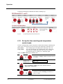
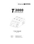
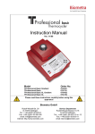
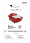
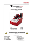
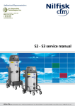
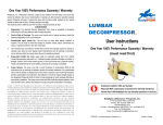
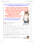
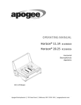
BioShake Series
Shaker and thermal mixer
Analytik Jena
Lifescience
Konrad-Zuse-Str. 1
07745 Jena
Phone:
e-mail:
Hotline:
+ 49 (3641) 77-94 00
Fax:
+ 49 (3641) 77-76 77 76
[email protected]
General information about Analytik Jena AG
on the internet: http://www.bio.analytik-jena.de
Edition – June 2013
Technical documentation made by:
Analytik Jena
This documentation describes the state of this product at the time of publishing. It
need not necessarily agree with future versions of the product.
Subject to change!
© Copyright 2013 Analytik Jena
Content
Content
1
Introduction ............................................................................. 3
1.1
Field of application ........................................................................................... 3
1.2
Information on the use of this manual .............................................................. 4
2
Safety instructions.................................................................. 5
2.1
Warning and safety symbols on the BioShake ................................................. 5
2.2
Safety and caution information ......................................................................... 5
2.3
General information .......................................................................................... 7
3
Delivery parts .......................................................................... 8
3.1
BioShake iQ ..................................................................................................... 8
3.2
BioShake XP .................................................................................................... 8
4
Installation ............................................................................... 9
5
Changing of adapter plates .................................................. 10
6
Operation ............................................................................... 11
6.1
Control panel of BioShake XP ........................................................................ 11
6.2
Control panel of BioShake iQ ......................................................................... 12
6.3
Standard functions ......................................................................................... 12
6.4
Set up time ..................................................................................................... 13
6.5
Set up mixing speed ....................................................................................... 13
6.6
Set up temperature......................................................................................... 15
6.7
Short mix ........................................................................................................ 15
6.8
Start / Stop ..................................................................................................... 15
6.9
Programming .................................................................................................. 15
6.10
Set up the time counting and temperature control mode ................................ 16
6.11
Set up the buzzer and programming control mode ........................................ 17
7
Tips for shaker operation ..................................................... 18
8
Specification ......................................................................... 19
8.1
Adapter for microplates, tubes and glass vials ............................................... 19
8.2
Technical specifications ................................................................................. 19
9
Ordering information ............................................................ 21
10
Maintenance and repair ........................................................ 24
10.1
Cleaning and maintenance............................................................................. 24
10.2
Servicing ........................................................................................................ 24
10.3
Replacement of spare parts ........................................................................... 24
10.4
Other accessories .......................................................................................... 24
User manual BioShake series
Issue 06/2013
1
Content
2
11
Service ................................................................................... 25
11.1
Instructions for return shipment ...................................................................... 25
12
Equipment Decontamination Certificate ............................. 26
13
Note for disposal of electric/electronic waste .................... 27
14
EC - Declaration of Conformity ............................................ 28
15
Warranty ................................................................................ 29
16
Table of figures ..................................................................... 31
Issue 06/2013
User manual BioShake series
Introduction
1
Introduction
1.1
Field of application
The BioShake Series is special designed for precise control of speed and temperature in
an apparatus with a footprint not bigger than 2 microplates side-by-side.
The apparatus offer an ultra-efficient, 3-dimensional shaking axis to mix samples in
tubes, glass vials or microplates (up to 1536 wells) without the need of spinning down
the samples after mixing. Even high density plates or low samples volumes are not a
problem for the Shaker.
BioShake mixers have an orbit diameter of 2.0 mm and a high maximum shaking
frequency of 3,000 rpm, allowing any model to easily mix standard and low volume
samples in tubes, glass vials and 96-well, 384-well or 1536-well microplates.
The apparatus are working very quiet due to a special patent pending dampening system
which relies upon ingenious counter-weight symmetry. They shake tubes to mix their
content but do not put vibrations on the entire work bench or robotic deck.
Reduced mass sample blocks provide for quick heating and accurate temperature
control across the whole block.
Fig. 1-1
User manual BioShake series
Correlation between mixing frequencies and mixing effects in dependence on the
filling level
Issue 06/2013
3
Information
1.2
Information on the use of this manual
The following warning and information symbols are used in this manual:
Danger! Dangerous touch voltage!
Caution!
Warning messages alert you to a specific procedure or practice which, if not followed
correctly, could cause personal injury.
Caution! Hot surface!
Contact with the surface can cause burns.
Attention!
Caution messages refer you to procedures which, if not observed, could result in
damage to the equipment.
Disconnect mains plug!
Note
This information must be observed to ensure correct function of the device.
The following systematic approach is introduced in the manual:
•
•
•
•
4
The chapters and figures are numbered consecutively.
Each image has its own caption.
A cross reference is indicated with an arrow (e.g. → Information on the use of this
manual pg. 4).
Working steps are numbered.
Issue 06/2013
User manual BioShake series
Safety instructions
2
Safety instructions
Read through this chapter carefully prior to commissioning the BioShake Series for your
own safety and for trouble-free operation.
Follow all the safety instructions explained in the manual, as well as all messages and
information displayed on the screen by the internal microcomputer.
2.1
Warning and safety symbols on the BioShake
The following warning and safety symbols are affixed on the BioShake:
Caution! Hot surface!
Contact with the surface can cause burns!
This symbol is affixed on the basis unit next to the heating surface of the block (only
BioShake iQ).
Disconnect mains plug!
This symbol is affixed on the rear of the device next to the mains input.
2.2
Safety and caution information
1. Do not operate the device in rooms where work is being carried out with explosive
substances.
2. Do not use this device to process any explosive, radioactive or highly reactive
substances.
3. Do not use this device to process any substances, which could create an
explosive atmosphere.
4. Danger! Electric shock from damage to device/power cable. Danger! Lethal
voltages inside the device.
5. Warning! General hazard point.
6. Warning! Injury from rapidly rotating holder. Injury from rapidly rotating imbalance
compensation. Injury from flying tubes and plates.
7. Warning! Injury from sample material being flung out. Injury from incorrect
vortexing.
8. Warning! Damage due to incorrect power supply.
User manual BioShake series
Issue 06/2013
5
Safety instructions
9. Caution! Damage to the display from mechanical pressure. Severe vibration.
10. Caution! Damage to electronic components caused by spilled liquids. Damage to
electronic components from condensation.
11. Caution! Poor safety due to missing operating manual. Caution when using
aggressive chemicals.
12. Please start even with minimal mixing frequencies to avoid overloading.
13. Only mix in sealed tubes and plates. Sample material can be flung out of open,
inadequately sealed or unstable tubes and plates.
14. When working with hazardous, toxic and pathogenic samples, always comply with
the nationally specified safety environment.
15. Please use the original power supply delivered by Analytik Jena | Biometra.
16. Please use the original accessories recommended by Analytik Jena | Biometra.
Pay particular attention to personal safety gear (gloves, clothing, glasses etc.), the
extraction hood and the safety class of the laboratory.
Read this section carefully and follow the instructions before
beginning installation and any procedure.
The unit must be placed on a horizontal solid work space.
The device must be saving from shocks and falling.
The unit must be placed in sufficient distance to heat registers or
radiators to ensure ambient temperature conditions in accordance
with the technical specifications (section 8.2).
Use the normal care and precaution one would use with any
electrical appliance.
Be sure to use a power cord with the same rating and of the same
type (three-wire with neutral conductor) as the one supplied with the
instrument.
Ensure that voltage and frequency of your power source match the
input voltage and frequency inscribed on the electrical rating label of
the power supply (AC/DC adaptor) and that the output voltage
matches the rating of the equipment. The AC/DC adaptor is
designed to work with a single-phase power system having a
grounded neutral conductor.
If you are not sure what type of power is supplied to your building
contact your facilities manager.
As BioShake is an electrical device do not spill large quantities of
liquid onto the device. Do not use it in an explosive atmosphere.
As parts of the device may generate electric, magnetic or
electromagnetic fields, keep parts away that may be affected (e.g.
data storage units).
6
Issue 06/2013
User manual BioShake series
Safety instructions
BioShake is capable of heating the plate surface up to 100 °C.
This temperature is high enough to cause serious burns if touched.
Use extreme caution at all times.
Never leave your unit accessible to others when it is hot.
Never touch the plate surface unless you are sure it is cold.
Use oven gloves if necessary.
Do not unscrew any part of BioShake except for the interchangeable
power supply, the power cord and different blocks.
Do not make any mechanical or electrical modifications to the
equipment.
Never do anything else with BioShake as intended in this manual.
Noncompliance of the safety instructions may lead to device
damage, loss of warranty and may cause serious personal injury as
well as death.
2.3
General information
Warning! Injury from sample material being flung out.
Sample material can be flung out of open, inadequately sealed or
unstable wells, plates and tubes.
•
Only mix in sealed tubes and plates
•
When working with hazardous, toxic and pathogenic
samples, always comply with nationally specified safety
environment. Pay particular attention to personal safety
gear (gloves, clothing, glasses etc.), the extraction hood
and the safety class of the laboratory.
When setting mixing frequency, adhere to the rules outlined in
Fig. 6-4 to 6-7.
User manual BioShake series
Issue 06/2013
7
Delivery parts
3
Delivery parts
3.1
BioShake iQ
(3)
1
BioShake iQ
2
Power supply
3
Power cord
Operating manual (no
picture)
(1)
(1)
Fig. 3-1
3.2
(2)
BioShake iQ (1) with power supply (2) and power cord (3)
BioShake XP
(3)
1
BioShake iQ
2
Power supply
3
Power cord
Operating manual (no
picture)
(1)
(1)
Fig. 3-2
8
(2)
BioShake XP (1) with power supply (2) and power cord (3)
Issue 06/2013
User manual BioShake series
Installation
4
Installation
Unpack and carefully check the instrument. Report any damage or missing items to your
local distributor.
If no damage is found place the device up on a stable horizontal surface.
Fig. 4-1
Connections at the rear side of device (BioShake iQ and BioShake XP)
Before starting to work with the BioShake:
Remove the cover plate before installing an adapter plate:
Loose the 3 torx screws with the torx screwer at the adapter packaging and remove the
cover plate.)
If the adapter will not be removed before installing an adapter, the adapter will not be
recognized by the device!
Place an adapter on the shaker (chapter 5: Changing of adapter plates).
Plug the external power supply (2) into the 24 V socket at the rear side of the BioShake
iQ or BioShake XP.
Plug the power cable (3) into the power supply (2) and into the wall socket.
Turn On the instrument.
It is advisable to carry out a test run at maximum speed to ensure that the device does
not move while mixing.
User manual BioShake series
Issue 06/2013
9
Changing of adapter plates
5
Changing of adapter plates
To change the adapter plates, please follow the subsequent steps:
Attention!
If the security cover plate or an adapter plate already be mounted, please remove it
first!
1.
Turn off the instrument!
2.
Remove all sample carriers B-3 (tubes, vials, microplates etc.).
3.
Loosen the 3 torx screws A-1, A-2 and A-3 by using the supplied screwdriver
(Torx size 8, rotate left).
4.
Take off the cover clate or adapter plate B-2 straight up and put it on a clean,
soft surface.
Mounting of the new adapter plate:
1.
Please take care to a clean, dirt-free and particle-free operation.
2.
Insert the new adapter plate straight into the impression of the plate holder B-1.
3.
Check the fixed position.
4.
Fix all torx screws A-1, A-2 und A-3 using clockwise rotation. Please take care
to uniform controlled tightening of screws to ensure a good fit.
5.
Please take care to good and tight fit of sample carriers B-3 (tubes, vials,
microplates etc.).
6.
Turn on the instrument! BioShake will recognize the different block types. All
pending information and indications are shown in the display.
B-3
A-2
B-2
A-3
A-1
B-1
Fig. 5-1
Mounting of adapter plates
Attention!
Heavier blocks may limit the shaking speed (see Fig. 6-6 Recommended maximum
mixing speeds)
10
Issue 06/2013
User manual BioShake series
Operation
6
Operation
The BioShake is designed for shaking (BioShake iQ and BioShake XP) and temperature
control (BioShake iQ) of liquids in tissue culture plates, microplates, tubes and glass
vials. Microplates or tubes have to be placed on the shaker platform of the BioShake.
The liquid to be shaken is introduced into the wells or tubes.
The automatic start up function of the unit ensures a gradual start of the shaking process
without sample splashing.
The drive is absolutely wear-free and maintenance-free.
6.1
Control panel of BioShake XP
The following picture shows the control panel of the BioShake XP.
Fig. 6-1
User manual BioShake series
Control panel of BioShake XP
Issue 06/2013
11
Operation
6.2
Fig. 6-2
6.3
Fig. 6-3
12
Control panel of BioShake iQ
Control panel of BioShake iQ
Standard functions
Standard functions (only for BioShake iQ and BioShake XP)
Issue 06/2013
User manual BioShake series
Operation
6.4
Set up time
Use time cursors to set the required operation time.
If the timer is not selected, pressing the Start / Stop will cause a
continuous operation of the shaker.
6.5
Set up mixing speed
It is possible to control mixing speeds from 200 rpm up to 3,000 rpm.
To set the mixing speeds use the mix buttons.
Required mixing speeds [rpm] for different tubes depending on
filling volume [%] for diluted fluids
Filling volume 0.2 ml tubes
0.5 ml tubes
1.5 ml tubes
2.0 ml tubes
25 %
1400 - 1800
1200 - 1600
1000 - 1300
1000 - 1300
50 %
1200 - 1500
1100 - 1300
1000 - 1200
900 - 1200
75 %
1000 - 1300
1000 - 1200
900 - 1100
900 - 1100
Fig. 6-4
Required mixing speeds depending on filling volume of tubes
Required mixing speeds [rpm] for microplates depending on filling
volume/well [%] for diluted fluids
Filling volume
96-well
(standard)
384-well
(standard)
384-well
(small-vol.)
1536-well
(standard)
10 %
1800 - 2200
2200 - 2600
2800 - 3000
2800 - 3000
25 %
1600 - 2000
2000 - 2400
2400 - 3000
2600 - 3000
50 %
1400 - 1800
1800 - 2200
2200 - 2600
2400 - 2600
75 %
1200 - 1600
1600 - 2000
2000 - 2400
2200 - 2600
Fig. 6-5
User manual BioShake series
Required mixing speeds depending on filling volume of microplates
Issue 06/2013
13
Operation
Maximal mixing speeds [rpm] for microplates depending on the
weight [g]
Type
Weight
1,400
2,500
3,000
x
Microplate
0 -80 g
Deep well plate
0 -120 g
Deep well plate
0 -150 g
Deep well plate
150 -300 g
Fig. 6-6
2,000
x
x
x
Recommended maximum mixing speeds
Adapter categories:
All adapters will be automatically detected while mounting on the instrument. The
allocation of the adapter to a particular category determines the properties.
Adapter
category
Cat 01
Cat 02
3,000
1,800
Cat 03
2,200
Cat 04
3,000
Cat 05
1,000
Cat 06
----
Cat 07
2,500
Cat 10
OEM
Fig. 6-7
14
Max.
rpm
Available adapters
Item no.
-
Description
A) Without adapter (heating function not available)
B) All non classified adapters (heating function not available)
848-1808-1061
Adapter for 24x 2.0 ml or 15x 0.5 ml tubes
848-1808-1062
Adapter for 24x 1.5 ml or 15x 0.5 ml tubes
848-1808-1063
Adapter for 40x 0.5 ml or 28x 0.2 ml tubes
848-1808-1065
848-1808-1066
Adapter for 35x 2.0 ml or 24x 0.5 ml tubes
Adapter for 35x 1.5 ml or 24x 0.5 tubes
848-1808-1067
Adapter for 35x Lysis tubes 0.5 – 2.0 ml
848-1808-1071
Adapter for 30x 2.0 ml glass vials
848-1808-1072
Adapter for 20x 4.0 ml glass vials
848-1808-1121
Deep well plate adapter – 96 well / 1,000 µl (Eppendorf)
848-1808-1131
Deep well plate adapter - 96 well / 500 µl (Eppendorf)
848-1808-1041
Microplate adapter - 96 well standard PCR plate, universal
848-1808-1064
Adapter for 96x 0.2 ml tubes
848-1808-1021
Microplate adapter - flat bottom
848-1808-1031
Microplate adapter (universal) - 96 well round bottom
848-1808-1093
Adapter-Falcon tubes – 4 x 50 ml or 2 x 15 ml
848-1808-1094
Adapter-Falcon-tubes – 12 x 15 ml
Not available at the time
848-1808-1022
Microplate adapter - flat bottom, high base
848-1808-1051
Microplate adapter - 384 well standard PCR plates
Customer specified
Mixing speed classification of adapters
Issue 06/2013
User manual BioShake series
Operation
All pending information and indications are shown in the display.
Display Line 1
Display Line 2
6.6
Adapter Cat.: 01
Max. Speed: 3000
Set up temperature
It is possible to control temperature from room temperature up to 99 °C.
To set the temperature use the Temp Buttons.
Attention!
Microplates melt at extremely high temperatures.
Only heat microplates made of polystyrene to a maximum of 70 °C
6.7
Short mix
By pressing Short Mix, the shaker will start up with the set
parameters. Releasing the Short Mix button will stop the shaker.
6.8
Start / Stop
By pressing Start / Stop, the shaker will start up with the set
parameters.
If you press Start / Stop again, the shaker will stop.
6.9
Programming
With the BioShake iQ and BioShake XP it is possible to have 2 automatic programs.
Both programs can have 3 different steps with different time, speed and temperature
settings for each step.
User manual BioShake series
Issue 06/2013
15
Operation
Program the BioShake iQ or BioShake XP with the following steps:
Fig. 6-8
6.10
Programming BioShake iQ or BioShake XP
Set up the time counting and temperature
control mode
The time counting function enables temperature control and/or mixing for a limited period
of time. There are two ways to measure the time of the temperature control processes.
Time control:
Temp control:
Time counting begins immediately when “Start/Stop” is pressed.
The Temp control mode is the standard mode. Time counting only
starts when the nominal temperature value has been reached.
To terminate the process earlier, press “Start/Stop” again.
Switch the TCMo mode with the following steps:
1.
+
To start press Temp(+) and P1 and hold for at least
3 seconds.
Display Line 1
Display Line 2
TCMo
Temp
BMo
auto
-
2.
By pressing Time(+) or Time(-) the shaker will switch between
Temp mode or Time mode.
3.
+
16
To finish press P1 and Temp(+) and hold for at
least 3 seconds.
Issue 06/2013
User manual BioShake series
Operation
6.11
Set up the buzzer and programming control
mode
The programming control mode enables buzzer and temperature control at the end of
automatic programs. There are two ways to set up the buzzer and temperature control
process.
auto mode:
At the end of automatic
programs:
•
•
•
3x short buzzer signals
Mixing is stopped
Temperature control is stopped
and switch off
User mode:
At the end of automatic
programs:
•
•
•
Short buzzer signal every 10 seconds
Mixing is stopped
Temperature control is enabled and
keep target temperature constant
Switch the BMo mode with the following steps:
1.
+
To start press Temp(+) and P1 and hold for at least
3 seconds.
Display Line 1
Display Line 2
TCMo
Temp
BMo
auto
-
2.
By pressing Mix(+) or Mix(-) the shaker will switch between
auto mode or user mode.
3.
+
User manual BioShake series
To finish press P1 and Temp(+) and hold for at
least 3 seconds.
Issue 06/2013
17
Tips for shaker operation
7
Tips for shaker operation
A wide variety of well plates are commercially
available.
To ensure that the plates are positioned
securely in the plate holder, they must
correspond with the ANIS/SBS Standard for
Microplates.
If the filled plate has a weight of more than 80
g, then the maximum rated shaking frequency
of 3,000 rpm may not be attainable with a
safety stand. Select a lower shaking frequency
in this case. However, there is no risk of
damage to the BioShake – even if the weight is
too high then the shaking action stops due to
excessive weight or excessive shaking
frequencies. As soon as you reduce the frequency, the unit will stand firm.
Maximum shaker platform load: 500 g (filled well plate).
The shaker is driven by a maintenance-free brushless motor which enables silent
operation and constant shaking speed independent of the load.
IMPORTANT NOTES:
18
•
Please start even with minimal mixing frequencies to avoid overloading.
•
Only mix in sealed tubes and plates. Sample material can be flung out of open,
inadequately sealed or unstable tubes and plates.
•
When working with hazardous, toxic and pathogenic samples, always comply with
the nationally specified safety environment.
•
Pay particular attention to personal safety gear (gloves, clothing, glasses etc., the
extraction hood and the safety class of the laboratory.
Issue 06/2013
User manual BioShake series
Specification
8
Specification
8.1
Adapter for microplates, tubes and glass vials
Analytik Jena | Biometra offers high precision adapter plates to allow a perfect fit for all
kinds of tubes, vials, microplates and other different disposables.
The adapter plates are optimized for an excellent heat transfer to the disposables and
enhance the uniformity over all wells and the heat up or cool down time.
The exchange of adapter plates can be performed very easily within one minute.
If you need an adapter plate for specially shaped micro plates, tubes or vials, so please
send us additional specific information about your used sample container: manufacturer,
description, article number.
You will receive your special formed adapter plate!
8.2
Technical specifications
BioShake XP, BioShake iQ
BioShake XP
Adapter plates
Microplates
Tubes
Glass vials
BioShake iQ
96-, 384- and 1536-well microplates (deep-well, v-well, square-well
and u-well shape)
0.2, 0.5, 1.5 and 2.0 ml tubes, Lysis Tubes 0.5 - 2.0 ml,
15 ml and 50 ml Falcon tubes
2.0 and 4.0 ml glass vials
Temperature
Regulation range
---
RT to 99 °C
Temperature setting
---
Regulation accuracy
Temperature accuracy
-----
Heat-up time
---
Active Cool-down time
---
0.1°C increment
adjustable from 0 °C to 99 °C
± 0.1°C
± 0.5 °C at 45 °C
± 0.7 °C at 75 °C
± 1.0 °C at 95 °C
10 min from RT to 95 °C
(approx. 7 °C/min)
---
Mixing
Mixing frequency
Mixing orbit
Speed setting resolution
Mixing regulation accuracy
Timer
Timer setting
Working / Alarm
User manual BioShake series
200 to 3,000 rpm (microplates)
200 to 1,800 rpm (tubes, glass vials)
Constant 2 mm
50 rpm increments
± 25 rpm
1 min - 99 h / with automatic switch to stand-by
Continuous working / audible alarm
Issue 06/2013
19
Specification
BioShake XP
BioShake iQ
Programming
Operation control
Programs
Program capacity
Micro controller
2 programs / definable buttons P1 and P2
3 steps / internal memory
Display
Display
Target values/actual values
Electrical
Operating voltages
Power supply
2 x 16 digits LCD-display with backlight (black)
Time, mixing frequency
Time, mixing frequency,
temperature
24 V DC input / 100 Watt
External power supply unit / 100-240 V AC, 50-60 Hz
Properties
Housing material
Operating range
Dimensions (WxDxH) [mm]
Weight [kg]
Aluminum anodized, silver
+5 °C to 45 °C (80 % max. relative humidity)
142 x 170 x 80
2.0
2.7
Technical specifications are subject to change!
20
Issue 06/2013
User manual BioShake series
Ordering information
9
Ordering information
Product
Order – No.
BioShake XP (100 – 240V, EU plug); without adapter plate
BioShake XP (100 – 240 V, US plug); without adapter plate
BioShake XP (100 – 240 V, Japan plug); without adapter plate
848-1808-0505
848-1808-0555
848-1808-0565
BioShake iQ (100 – 240V, EU plug); without adapter plate
BioShake iQ (100 – 240 V, US plug); without adapter plate
BioShake iQ (100 – 240 V, Japan plug); without adapter plate
848-1808-0506
848-1808-0556
848-1808-0566
ADAPTER* for MICROPLATES
Microplate adapter – Flat bottom
Microplate adapter –flat bottom, high base, universal
Microplate adapter – 96 well round bottom, universal
Microplate adapter – 96 well standard PCR plate, universal
Microplate adapter – 384 well standard PCR plate, universal
848-1808-1021
848-1808-1022
848-1808-1031
848-1808-1041
848-1808-1051
ADAPTER* for DEEP WELL PLATES
Adapter – Eppendorf deep well plate 96/1000 µl
Adapter – Eppendorf Deep well Plate 96/500 µl
848-1808-1121
848-1808-1131
ADAPTER* for TUBES
Adapter – 24 x 2.0 ml or 15 x 0.5 ml tubes
Adapter – 24 x 1.5 ml or 15 x 0.5 ml tubes
Adapter – 40 x 0.5 ml or 28 x 0.2 ml tubes
Adapter – 96 x 0.2 ml tubes
Adapter – 35 x 2.0 ml or 24 x 0.5 ml tubes
Adapter – 35 x 1.5 ml or 24 x 0.5 ml tubes
Adapter – 35 x Lysis tubes 0.5 – 2.0 ml
848-1808-1061
848-1808-1062
848-1808-1063
848-1808-1064
848-1808-1065
848-1808-1066
848-1808-1067
ADAPTER* for FALCON TUBES
Adapter-Falcon tubes – 4 x 50 ml or 2 x 15 ml
Adapter-Falcon tubes – 12 x 15 ml
848-1808-1093
848-1808-1094
ADAPTER* for GLASS VIALS
Adapter – 30 x 2.0 ml glass vials
Adapter – 20 x 4.0 ml glass vials
848-1808-1071
848-1808-1072
CUSTOMIZED ADAPTERS*
Customized adapters for specifically shaped microplates, tubes
or vials (on request)
848-1808-1000
* All Adapters are delivered incl. 3 fixation screws and screwdriver
User manual BioShake series
Issue 06/2013
21
Ordering information
Product
Order – No.
Spare Parts
Power supply for BioShake XP (100 – 240 V AC, 50 – 60 Hz, 24 V DC, 60 W)
848-1808-9010
Power supply for BioShake iQ (100 – 240 V AC, 50 – 60 Hz, 24 V DC, 108 W)
848-1808-9011
Power cord (Europe)
Power cord (USA)
Power cord (Japan)
848-1808-9101
848-1808-9110
848-1808-9111
Fixation screws for Security Cover Plate or Adapter (3 pcs.)
Fixation springs for BioShake XP/iQ (8 pcs.)
Security Cover Plate (incl. 3 fixation screws and tool)
848-1808-9006
848-1808-9007
848-1808-9008
Please use the original accessories recommended by Analytik Jena | Biometra.
Using spare parts or disposables which we have not recommended can reduce the
precision, accuracy and life of the BioShake. We do not honour any warranty or accept
any responsibility for damage resulting from such action.
22
Issue 06/2013
User manual BioShake series
Ordering information
Fig. 9-1
User manual BioShake series
BioShake adapters
Issue 06/2013
23
Maintenance and repair
10
Maintenance and repair
10.1
Cleaning and maintenance
The device is maintenance-free. Before cleaning the BioShake, disconnect the power
cord and make sure that the temperature at the contact surface is below +40 °C.
If contaminated the device may be cleaned using a mild soap solution and water or an
alcohol-based disinfectant.
Do not immerse the unit in liquid.
10.2
Servicing
Regular servicing is not necessary. Should it become necessary to repair the equipment,
please contact our Service Department.
10.3
Replacement of spare parts
Only original spare parts mentioned in these operating instructions are allowed.
10.4
Other accessories
There are no accessory parts for this instruments.
24
Issue 06/2013
User manual BioShake series
Service
11
Service
Should you have any problems with this unit, please contact our service department or
your local Analytik Jena | Biometra distributor.
Analytik Jena AG
Service Department Life Science
Konrad-Zuse-Straße 1
D-07745 Jena
Tel.:
+49 (0) 36 41 / 77-94 11
Fax:
+49 (0) 36 61 / 77-76 77 76
e-mail: [email protected]
Internet: www.bio.analytik-jena.com
Attention!
If you would like to send the unit back to us, please read the following instructions.
11.1
Instructions for return shipment
•
Return only defective devices. For technical problems which are not definitively
recognisable as device faults please contact the technical service department at
Analytik Jena Life Science (Tel.: +49 (0) 36 41 / 77-94 11, Fax: +49 (0) 36 61 / 7776 77 76, e- mail: [email protected])
•
Please contact our service department for providing a return material
authorization number (RMA). This number has to be applied clearly visible to the
outer box. Returns without the RMA will be not be accepted!
Important!
Carefully clean all parts of the instrument from residues, and of biologically dangerous,
chemical or radioactive contaminants. If an instrument is contaminated, Analytik Jena |
Biometra will be forced to refuse to accept the device. The sender of the repair order will
be held liable for possible damages and losses resulting from insufficient
decontamination of the device.
•
Please prepare written confirmation (use the “Equipment Decontamination
Declaration” following on the next page) that the device is free of biologically
dangerous, chemical or radioactive contaminants. This confirmation must be
attached to the outside of the packaging.
•
Use the original packing or a similarly robust packing when returning the device. If
not available, contact Analytik Jena | Biometra or your local distributor.
•
Label the outside of the box with “CAUTION! SENSITIVE INSTRUMENT!” and the
RAN number sticker. Attach the Decontamination Declaration!
•
Please enclose a note which contains the following:
User manual BioShake series
a)
Sender’s name and address,
b)
Name of a contact person for further inquiries with telephone number.
c)
Precise description of the fault, which also reveals during which
procedures the fault occurred, if possible.
Issue 06/2013
25
Equipment Decontamination Certificate
12
Equipment Decontamination Certificate
To enable us to comply with german law (i.e. §71 StrlSchV, §17 GefStoffV and §19
ChemG) and to avoid exposure to hazardous materials during handling or repair, please
complete this form, prior to the equipment leaving your laboratory.
COMPANY / INSTITUTE
ADRESS
PHONE NO.
FAX NO.
E-MAIL
EQUIPMENT
MODEL
SERIAL NO.
If on loan / evaluation Start date:
Finish date:
Hazardous material used with this equipment:
Method of cleaning / decontamination:
The equipment has been cleaned and decontaminated:
Name
Position
(HEAD OF DIV./ DEP./ INSTITUTE / COMPANY)
SIGNED
DATE
PLEASE RETURN THIS FORM TO ANALYTIK JENA | BIOMETRA OR YOUR LOCAL
ANLYTIK JENA | BIOMETRA DISTRIBUTOR TOGETHER WITH THE EQUIPMENT.
PLEASE ATTACH THIS CERTIFICATE OUTSIDE THE PACKAGING. INSTRUMENTS
WITHOUT THIS CERTIFICATE ATTACHED WILL BE RETURNED TO SENDER.
General Information for Decontamination:
Please contact your responsible health & safety officer for details.
Use of radioactive substances:
Please contact your responsible person for details.
Use of genetically change organism or parts of those:
Please contact your responsible person for details.
26
Issue 06/2013
User manual BioShake series
Note for disposal of electric/electronic waste
13
Note for disposal of electric/electronic waste
This symbol (the crossed-out wheelie bin) means, that this product should be brought to
the return systems and/or separate systems available to end-users according to yours
country regulations, when this product has reached the end of its lifetime!
For details, please contact your local distributor!
This symbol applies only to the countries within the EEA*.
*EEA = European Economics Area, comprising all EU-members plus Norway, Iceland
and Liechtenstein.
User manual BioShake series
Issue 06/2013
27
EC - Declaration of Conformity
EU - Konformitätserklärung
14
EC - Declaration of Conformity
EU - Konformitätserklärung
May 2011
im Sinne der EG-Richtlinie über elektrische Betriebsmittel zur Verwendung innerhalb
bestimmter Spannungsgrenzen 2006/95/EG
following the EC directive about electrical equipment for use within certain limits of
voltage 2006/95/EC
und / and
im Sinne der EG-Richtlinie für die elektromagnetische Verträglichkeit 2004/108/EG.
following the EC directive about the electromagnetic compatibility 2004/108/EC.
Hiermit erklären wir, dass folgende Shaker
Herewith we declare that the following Shakers
Typ / type:
BioShake XP, BioShake iQ,
Best.-Nr. / Order No.
848-1808-0505, 848-1808-0555, 848-1808-0565,
848-1808-0506, 848-1808-0556, 848-1808-0566
den grundlegenden Anforderungen der
corresponds to the basic requirements of
EG-Niederspannungsrichtlinie 2006/95/EG und der
EC low voltage directive 2006/95/EC and the
EG-Richtlinie über die elektromagnetische Verträglichkeit 2004/108/EG entsprechen.
EC directive about the electromagnetic compatibility 2004/108/EC.
Quality Manager
28
Issue 06/2013
User manual BioShake series
Warranty
15
Warranty
This laboratory instrument is produced with the highest practical standards of materials,
workmanship, and design. The design and manufacture of parts have been conceived
with one purpose - to produce units which will give satisfactory service.
Analytik Jena | Biometra guarantees this unit to be free from defects in materials or
workmanship under normal use or service for 24 month from date of shipment.
If, during this time, this unit proves defective in materials or workmanship, Analytik Jena |
Biometra will repair or replace it free of charge if returned to us prepaid.
This guarantee does not cover damage in transit, damage caused by carelessness,
misuse or neglect, or unsatisfactory performance as a result of conditions beyond our
control; or consequential losses as a result of failure of our product.
Analytik Jena AG
Life Science
Biometra Service Department
Konrad-Zuse-Straße 1
Rudolf-Wissell-Str. 14-16
D-07745 Jena
D-37079 Göttingen
Tel:
+49 (0) 36 41 / 77-94 00
Tel.: +49 (0)5 51 50 68 6-10 or -12
Fax:
+49 (0) 36 61 / 77-76 77 76
Fax.:
+49 (0)5 51 50 68 6-11
e-mail: [email protected]
e-mail: [email protected]
Internet: www.bio.analytik-jena.com
Internet: www.bio.analytik-jena.com
User manual BioShake series
Issue 06/2013
29
Table of figures
16
Table of figures
Fig. 1-1
Correlation between mixing frequencies and mixing effects in dependence
on the filling level ............................................................................................. 3
Fig. 3-1
BioShake iQ (1) with power supply (2) and power cord (3) ............................. 8
Fig. 3-2
BioShake XP (1) with power supply (2) and power cord (3) ............................ 8
Fig. 4-1
Connections at the rear side of device (BioShake iQ and BioShake XP) ........ 9
Fig. 5-1
Mounting of adapter plates ............................................................................ 10
Fig. 6-1
Control panel of BioShake XP ....................................................................... 11
Fig. 6-2
Control panel of BioShake iQ ........................................................................ 12
Fig. 6-3
Standard functions (only for BioShake iQ and BioShake XP) ....................... 12
Fig. 6-4
Required mixing speeds depending on filling volume of tubes ...................... 13
Fig. 6-5
Required mixing speeds depending on filling volume of microplates ............ 13
Fig. 6-6
Recommended maximum mixing speeds...................................................... 14
Fig. 6-7
Mixing speed classification of adapters ......................................................... 14
Fig. 6-8
Programming BioShake iQ or BioShake XP.................................................. 16
Fig. 9-1
BioShake adapters ........................................................................................ 23
User manual BioShake series
Issue 06/2013
31
Content
Content
1
Introduction ............................................................................. 3
1.1
Field of application ........................................................................................... 3
1.2
Information on the use of this manual .............................................................. 4
2
Safety instructions.................................................................. 5
2.1
Warning and safety symbols on the BioShake ................................................. 5
2.2
Safety and caution information ......................................................................... 5
2.3
General information .......................................................................................... 7
3
Delivery parts .......................................................................... 8
3.1
BioShake iQ ..................................................................................................... 8
3.2
BioShake XP .................................................................................................... 8
4
Installation ............................................................................... 9
5
Changing of adapter plates .................................................. 10
6
Operation ............................................................................... 11
6.1
Control panel of BioShake XP ........................................................................ 11
6.2
Control panel of BioShake iQ ......................................................................... 12
6.3
Standard functions ......................................................................................... 12
6.4
Set up time ..................................................................................................... 13
6.5
Set up mixing speed ....................................................................................... 13
6.6
Set up temperature......................................................................................... 15
6.7
Short mix ........................................................................................................ 15
6.8
Start / Stop ..................................................................................................... 15
6.9
Programming .................................................................................................. 15
6.10
Set up the time counting and temperature control mode ................................ 16
6.11
Set up the buzzer and programming control mode ........................................ 17
7
Tips for shaker operation ..................................................... 18
8
Specification ......................................................................... 19
8.1
Adapter for microplates, tubes and glass vials ............................................... 19
8.2
Technical specifications ................................................................................. 19
9
Ordering information ............................................................ 21
10
Maintenance and repair ........................................................ 24
10.1
Cleaning and maintenance............................................................................. 24
10.2
Servicing ........................................................................................................ 24
10.3
Replacement of spare parts ........................................................................... 24
10.4
Other accessories .......................................................................................... 24
User manual BioShake series
Issue 06/2013
1
Content
2
11
Service ................................................................................... 25
11.1
Instructions for return shipment ...................................................................... 25
12
Equipment Decontamination Certificate ............................. 26
13
Note for disposal of electric/electronic waste .................... 27
14
EC - Declaration of Conformity ............................................ 28
15
Warranty ................................................................................ 29
16
Table of figures ..................................................................... 31
Issue 06/2013
User manual BioShake series
Introduction
1
Introduction
1.1
Field of application
The BioShake Series is special designed for precise control of speed and temperature in
an apparatus with a footprint not bigger than 2 microplates side-by-side.
The apparatus offer an ultra-efficient, 3-dimensional shaking axis to mix samples in
tubes, glass vials or microplates (up to 1536 wells) without the need of spinning down
the samples after mixing. Even high density plates or low samples volumes are not a
problem for the Shaker.
BioShake mixers have an orbit diameter of 2.0 mm and a high maximum shaking
frequency of 3,000 rpm, allowing any model to easily mix standard and low volume
samples in tubes, glass vials and 96-well, 384-well or 1536-well microplates.
The apparatus are working very quiet due to a special patent pending dampening system
which relies upon ingenious counter-weight symmetry. They shake tubes to mix their
content but do not put vibrations on the entire work bench or robotic deck.
Reduced mass sample blocks provide for quick heating and accurate temperature
control across the whole block.
Fig. 1-1
User manual BioShake series
Correlation between mixing frequencies and mixing effects in dependence on the
filling level
Issue 06/2013
3
Information
1.2
Information on the use of this manual
The following warning and information symbols are used in this manual:
Danger! Dangerous touch voltage!
Caution!
Warning messages alert you to a specific procedure or practice which, if not followed
correctly, could cause personal injury.
Caution! Hot surface!
Contact with the surface can cause burns.
Attention!
Caution messages refer you to procedures which, if not observed, could result in
damage to the equipment.
Disconnect mains plug!
Note
This information must be observed to ensure correct function of the device.
The following systematic approach is introduced in the manual:
•
•
•
•
4
The chapters and figures are numbered consecutively.
Each image has its own caption.
A cross reference is indicated with an arrow (e.g. → Information on the use of this
manual pg. 4).
Working steps are numbered.
Issue 06/2013
User manual BioShake series
Safety instructions
2
Safety instructions
Read through this chapter carefully prior to commissioning the BioShake Series for your
own safety and for trouble-free operation.
Follow all the safety instructions explained in the manual, as well as all messages and
information displayed on the screen by the internal microcomputer.
2.1
Warning and safety symbols on the BioShake
The following warning and safety symbols are affixed on the BioShake:
Caution! Hot surface!
Contact with the surface can cause burns!
This symbol is affixed on the basis unit next to the heating surface of the block (only
BioShake iQ).
Disconnect mains plug!
This symbol is affixed on the rear of the device next to the mains input.
2.2
Safety and caution information
1. Do not operate the device in rooms where work is being carried out with explosive
substances.
2. Do not use this device to process any explosive, radioactive or highly reactive
substances.
3. Do not use this device to process any substances, which could create an
explosive atmosphere.
4. Danger! Electric shock from damage to device/power cable. Danger! Lethal
voltages inside the device.
5. Warning! General hazard point.
6. Warning! Injury from rapidly rotating holder. Injury from rapidly rotating imbalance
compensation. Injury from flying tubes and plates.
7. Warning! Injury from sample material being flung out. Injury from incorrect
vortexing.
8. Warning! Damage due to incorrect power supply.
User manual BioShake series
Issue 06/2013
5
Safety instructions
9. Caution! Damage to the display from mechanical pressure. Severe vibration.
10. Caution! Damage to electronic components caused by spilled liquids. Damage to
electronic components from condensation.
11. Caution! Poor safety due to missing operating manual. Caution when using
aggressive chemicals.
12. Please start even with minimal mixing frequencies to avoid overloading.
13. Only mix in sealed tubes and plates. Sample material can be flung out of open,
inadequately sealed or unstable tubes and plates.
14. When working with hazardous, toxic and pathogenic samples, always comply with
the nationally specified safety environment.
15. Please use the original power supply delivered by Analytik Jena | Biometra.
16. Please use the original accessories recommended by Analytik Jena | Biometra.
Pay particular attention to personal safety gear (gloves, clothing, glasses etc.), the
extraction hood and the safety class of the laboratory.
Read this section carefully and follow the instructions before
beginning installation and any procedure.
The unit must be placed on a horizontal solid work space.
The device must be saving from shocks and falling.
The unit must be placed in sufficient distance to heat registers or
radiators to ensure ambient temperature conditions in accordance
with the technical specifications (section 8.2).
Use the normal care and precaution one would use with any
electrical appliance.
Be sure to use a power cord with the same rating and of the same
type (three-wire with neutral conductor) as the one supplied with the
instrument.
Ensure that voltage and frequency of your power source match the
input voltage and frequency inscribed on the electrical rating label of
the power supply (AC/DC adaptor) and that the output voltage
matches the rating of the equipment. The AC/DC adaptor is
designed to work with a single-phase power system having a
grounded neutral conductor.
If you are not sure what type of power is supplied to your building
contact your facilities manager.
As BioShake is an electrical device do not spill large quantities of
liquid onto the device. Do not use it in an explosive atmosphere.
As parts of the device may generate electric, magnetic or
electromagnetic fields, keep parts away that may be affected (e.g.
data storage units).
6
Issue 06/2013
User manual BioShake series
Safety instructions
BioShake is capable of heating the plate surface up to 100 °C.
This temperature is high enough to cause serious burns if touched.
Use extreme caution at all times.
Never leave your unit accessible to others when it is hot.
Never touch the plate surface unless you are sure it is cold.
Use oven gloves if necessary.
Do not unscrew any part of BioShake except for the interchangeable
power supply, the power cord and different blocks.
Do not make any mechanical or electrical modifications to the
equipment.
Never do anything else with BioShake as intended in this manual.
Noncompliance of the safety instructions may lead to device
damage, loss of warranty and may cause serious personal injury as
well as death.
2.3
General information
Warning! Injury from sample material being flung out.
Sample material can be flung out of open, inadequately sealed or
unstable wells, plates and tubes.
•
Only mix in sealed tubes and plates
•
When working with hazardous, toxic and pathogenic
samples, always comply with nationally specified safety
environment. Pay particular attention to personal safety
gear (gloves, clothing, glasses etc.), the extraction hood
and the safety class of the laboratory.
When setting mixing frequency, adhere to the rules outlined in
Fig. 6-4 to 6-7.
User manual BioShake series
Issue 06/2013
7
Delivery parts
3
Delivery parts
3.1
BioShake iQ
(3)
1
BioShake iQ
2
Power supply
3
Power cord
Operating manual (no
picture)
(1)
(1)
Fig. 3-1
3.2
(2)
BioShake iQ (1) with power supply (2) and power cord (3)
BioShake XP
(3)
1
BioShake iQ
2
Power supply
3
Power cord
Operating manual (no
picture)
(1)
(1)
Fig. 3-2
8
(2)
BioShake XP (1) with power supply (2) and power cord (3)
Issue 06/2013
User manual BioShake series
Installation
4
Installation
Unpack and carefully check the instrument. Report any damage or missing items to your
local distributor.
If no damage is found place the device up on a stable horizontal surface.
Fig. 4-1
Connections at the rear side of device (BioShake iQ and BioShake XP)
Before starting to work with the BioShake:
Remove the cover plate before installing an adapter plate:
Loose the 3 torx screws with the torx screwer at the adapter packaging and remove the
cover plate.)
If the adapter will not be removed before installing an adapter, the adapter will not be
recognized by the device!
Place an adapter on the shaker (chapter 5: Changing of adapter plates).
Plug the external power supply (2) into the 24 V socket at the rear side of the BioShake
iQ or BioShake XP.
Plug the power cable (3) into the power supply (2) and into the wall socket.
Turn On the instrument.
It is advisable to carry out a test run at maximum speed to ensure that the device does
not move while mixing.
User manual BioShake series
Issue 06/2013
9
Changing of adapter plates
5
Changing of adapter plates
To change the adapter plates, please follow the subsequent steps:
Attention!
If the security cover plate or an adapter plate already be mounted, please remove it
first!
1.
Turn off the instrument!
2.
Remove all sample carriers B-3 (tubes, vials, microplates etc.).
3.
Loosen the 3 torx screws A-1, A-2 and A-3 by using the supplied screwdriver
(Torx size 8, rotate left).
4.
Take off the cover clate or adapter plate B-2 straight up and put it on a clean,
soft surface.
Mounting of the new adapter plate:
1.
Please take care to a clean, dirt-free and particle-free operation.
2.
Insert the new adapter plate straight into the impression of the plate holder B-1.
3.
Check the fixed position.
4.
Fix all torx screws A-1, A-2 und A-3 using clockwise rotation. Please take care
to uniform controlled tightening of screws to ensure a good fit.
5.
Please take care to good and tight fit of sample carriers B-3 (tubes, vials,
microplates etc.).
6.
Turn on the instrument! BioShake will recognize the different block types. All
pending information and indications are shown in the display.
B-3
A-2
B-2
A-3
A-1
B-1
Fig. 5-1
Mounting of adapter plates
Attention!
Heavier blocks may limit the shaking speed (see Fig. 6-6 Recommended maximum
mixing speeds)
10
Issue 06/2013
User manual BioShake series
Operation
6
Operation
The BioShake is designed for shaking (BioShake iQ and BioShake XP) and temperature
control (BioShake iQ) of liquids in tissue culture plates, microplates, tubes and glass
vials. Microplates or tubes have to be placed on the shaker platform of the BioShake.
The liquid to be shaken is introduced into the wells or tubes.
The automatic start up function of the unit ensures a gradual start of the shaking process
without sample splashing.
The drive is absolutely wear-free and maintenance-free.
6.1
Control panel of BioShake XP
The following picture shows the control panel of the BioShake XP.
Fig. 6-1
User manual BioShake series
Control panel of BioShake XP
Issue 06/2013
11
Operation
6.2
Fig. 6-2
6.3
Fig. 6-3
12
Control panel of BioShake iQ
Control panel of BioShake iQ
Standard functions
Standard functions (only for BioShake iQ and BioShake XP)
Issue 06/2013
User manual BioShake series
Operation
6.4
Set up time
Use time cursors to set the required operation time.
If the timer is not selected, pressing the Start / Stop will cause a
continuous operation of the shaker.
6.5
Set up mixing speed
It is possible to control mixing speeds from 200 rpm up to 3,000 rpm.
To set the mixing speeds use the mix buttons.
Required mixing speeds [rpm] for different tubes depending on
filling volume [%] for diluted fluids
Filling volume 0.2 ml tubes
0.5 ml tubes
1.5 ml tubes
2.0 ml tubes
25 %
1400 - 1800
1200 - 1600
1000 - 1300
1000 - 1300
50 %
1200 - 1500
1100 - 1300
1000 - 1200
900 - 1200
75 %
1000 - 1300
1000 - 1200
900 - 1100
900 - 1100
Fig. 6-4
Required mixing speeds depending on filling volume of tubes
Required mixing speeds [rpm] for microplates depending on filling
volume/well [%] for diluted fluids
Filling volume
96-well
(standard)
384-well
(standard)
384-well
(small-vol.)
1536-well
(standard)
10 %
1800 - 2200
2200 - 2600
2800 - 3000
2800 - 3000
25 %
1600 - 2000
2000 - 2400
2400 - 3000
2600 - 3000
50 %
1400 - 1800
1800 - 2200
2200 - 2600
2400 - 2600
75 %
1200 - 1600
1600 - 2000
2000 - 2400
2200 - 2600
Fig. 6-5
User manual BioShake series
Required mixing speeds depending on filling volume of microplates
Issue 06/2013
13
Operation
Maximal mixing speeds [rpm] for microplates depending on the
weight [g]
Type
Weight
1,400
2,500
3,000
x
Microplate
0 -80 g
Deep well plate
0 -120 g
Deep well plate
0 -150 g
Deep well plate
150 -300 g
Fig. 6-6
2,000
x
x
x
Recommended maximum mixing speeds
Adapter categories:
All adapters will be automatically detected while mounting on the instrument. The
allocation of the adapter to a particular category determines the properties.
Adapter
category
Cat 01
Cat 02
3,000
1,800
Cat 03
2,200
Cat 04
3,000
Cat 05
1,000
Cat 06
----
Cat 07
2,500
Cat 10
OEM
Fig. 6-7
14
Max.
rpm
Available adapters
Item no.
-
Description
A) Without adapter (heating function not available)
B) All non classified adapters (heating function not available)
848-1808-1061
Adapter for 24x 2.0 ml or 15x 0.5 ml tubes
848-1808-1062
Adapter for 24x 1.5 ml or 15x 0.5 ml tubes
848-1808-1063
Adapter for 40x 0.5 ml or 28x 0.2 ml tubes
848-1808-1065
848-1808-1066
Adapter for 35x 2.0 ml or 24x 0.5 ml tubes
Adapter for 35x 1.5 ml or 24x 0.5 tubes
848-1808-1067
Adapter for 35x Lysis tubes 0.5 – 2.0 ml
848-1808-1071
Adapter for 30x 2.0 ml glass vials
848-1808-1072
Adapter for 20x 4.0 ml glass vials
848-1808-1121
Deep well plate adapter – 96 well / 1,000 µl (Eppendorf)
848-1808-1131
Deep well plate adapter - 96 well / 500 µl (Eppendorf)
848-1808-1041
Microplate adapter - 96 well standard PCR plate, universal
848-1808-1064
Adapter for 96x 0.2 ml tubes
848-1808-1021
Microplate adapter - flat bottom
848-1808-1031
Microplate adapter (universal) - 96 well round bottom
848-1808-1093
Adapter-Falcon tubes – 4 x 50 ml or 2 x 15 ml
848-1808-1094
Adapter-Falcon-tubes – 12 x 15 ml
Not available at the time
848-1808-1022
Microplate adapter - flat bottom, high base
848-1808-1051
Microplate adapter - 384 well standard PCR plates
Customer specified
Mixing speed classification of adapters
Issue 06/2013
User manual BioShake series
Operation
All pending information and indications are shown in the display.
Display Line 1
Display Line 2
6.6
Adapter Cat.: 01
Max. Speed: 3000
Set up temperature
It is possible to control temperature from room temperature up to 99 °C.
To set the temperature use the Temp Buttons.
Attention!
Microplates melt at extremely high temperatures.
Only heat microplates made of polystyrene to a maximum of 70 °C
6.7
Short mix
By pressing Short Mix, the shaker will start up with the set
parameters. Releasing the Short Mix button will stop the shaker.
6.8
Start / Stop
By pressing Start / Stop, the shaker will start up with the set
parameters.
If you press Start / Stop again, the shaker will stop.
6.9
Programming
With the BioShake iQ and BioShake XP it is possible to have 2 automatic programs.
Both programs can have 3 different steps with different time, speed and temperature
settings for each step.
User manual BioShake series
Issue 06/2013
15
Operation
Program the BioShake iQ or BioShake XP with the following steps:
Fig. 6-8
6.10
Programming BioShake iQ or BioShake XP
Set up the time counting and temperature
control mode
The time counting function enables temperature control and/or mixing for a limited period
of time. There are two ways to measure the time of the temperature control processes.
Time control:
Temp control:
Time counting begins immediately when “Start/Stop” is pressed.
The Temp control mode is the standard mode. Time counting only
starts when the nominal temperature value has been reached.
To terminate the process earlier, press “Start/Stop” again.
Switch the TCMo mode with the following steps:
1.
+
To start press Temp(+) and P1 and hold for at least
3 seconds.
Display Line 1
Display Line 2
TCMo
Temp
BMo
auto
-
2.
By pressing Time(+) or Time(-) the shaker will switch between
Temp mode or Time mode.
3.
+
16
To finish press P1 and Temp(+) and hold for at
least 3 seconds.
Issue 06/2013
User manual BioShake series
Operation
6.11
Set up the buzzer and programming control
mode
The programming control mode enables buzzer and temperature control at the end of
automatic programs. There are two ways to set up the buzzer and temperature control
process.
auto mode:
At the end of automatic
programs:
•
•
•
3x short buzzer signals
Mixing is stopped
Temperature control is stopped
and switch off
User mode:
At the end of automatic
programs:
•
•
•
Short buzzer signal every 10 seconds
Mixing is stopped
Temperature control is enabled and
keep target temperature constant
Switch the BMo mode with the following steps:
1.
+
To start press Temp(+) and P1 and hold for at least
3 seconds.
Display Line 1
Display Line 2
TCMo
Temp
BMo
auto
-
2.
By pressing Mix(+) or Mix(-) the shaker will switch between
auto mode or user mode.
3.
+
User manual BioShake series
To finish press P1 and Temp(+) and hold for at
least 3 seconds.
Issue 06/2013
17
Tips for shaker operation
7
Tips for shaker operation
A wide variety of well plates are commercially
available.
To ensure that the plates are positioned
securely in the plate holder, they must
correspond with the ANIS/SBS Standard for
Microplates.
If the filled plate has a weight of more than 80
g, then the maximum rated shaking frequency
of 3,000 rpm may not be attainable with a
safety stand. Select a lower shaking frequency
in this case. However, there is no risk of
damage to the BioShake – even if the weight is
too high then the shaking action stops due to
excessive weight or excessive shaking
frequencies. As soon as you reduce the frequency, the unit will stand firm.
Maximum shaker platform load: 500 g (filled well plate).
The shaker is driven by a maintenance-free brushless motor which enables silent
operation and constant shaking speed independent of the load.
IMPORTANT NOTES:
18
•
Please start even with minimal mixing frequencies to avoid overloading.
•
Only mix in sealed tubes and plates. Sample material can be flung out of open,
inadequately sealed or unstable tubes and plates.
•
When working with hazardous, toxic and pathogenic samples, always comply with
the nationally specified safety environment.
•
Pay particular attention to personal safety gear (gloves, clothing, glasses etc., the
extraction hood and the safety class of the laboratory.
Issue 06/2013
User manual BioShake series
Specification
8
Specification
8.1
Adapter for microplates, tubes and glass vials
Analytik Jena | Biometra offers high precision adapter plates to allow a perfect fit for all
kinds of tubes, vials, microplates and other different disposables.
The adapter plates are optimized for an excellent heat transfer to the disposables and
enhance the uniformity over all wells and the heat up or cool down time.
The exchange of adapter plates can be performed very easily within one minute.
If you need an adapter plate for specially shaped micro plates, tubes or vials, so please
send us additional specific information about your used sample container: manufacturer,
description, article number.
You will receive your special formed adapter plate!
8.2
Technical specifications
BioShake XP, BioShake iQ
BioShake XP
Adapter plates
Microplates
Tubes
Glass vials
BioShake iQ
96-, 384- and 1536-well microplates (deep-well, v-well, square-well
and u-well shape)
0.2, 0.5, 1.5 and 2.0 ml tubes, Lysis Tubes 0.5 - 2.0 ml,
15 ml and 50 ml Falcon tubes
2.0 and 4.0 ml glass vials
Temperature
Regulation range
---
RT to 99 °C
Temperature setting
---
Regulation accuracy
Temperature accuracy
-----
Heat-up time
---
Active Cool-down time
---
0.1°C increment
adjustable from 0 °C to 99 °C
± 0.1°C
± 0.5 °C at 45 °C
± 0.7 °C at 75 °C
± 1.0 °C at 95 °C
10 min from RT to 95 °C
(approx. 7 °C/min)
---
Mixing
Mixing frequency
Mixing orbit
Speed setting resolution
Mixing regulation accuracy
Timer
Timer setting
Working / Alarm
User manual BioShake series
200 to 3,000 rpm (microplates)
200 to 1,800 rpm (tubes, glass vials)
Constant 2 mm
50 rpm increments
± 25 rpm
1 min - 99 h / with automatic switch to stand-by
Continuous working / audible alarm
Issue 06/2013
19
Specification
BioShake XP
BioShake iQ
Programming
Operation control
Programs
Program capacity
Micro controller
2 programs / definable buttons P1 and P2
3 steps / internal memory
Display
Display
Target values/actual values
Electrical
Operating voltages
Power supply
2 x 16 digits LCD-display with backlight (black)
Time, mixing frequency
Time, mixing frequency,
temperature
24 V DC input / 100 Watt
External power supply unit / 100-240 V AC, 50-60 Hz
Properties
Housing material
Operating range
Dimensions (WxDxH) [mm]
Weight [kg]
Aluminum anodized, silver
+5 °C to 45 °C (80 % max. relative humidity)
142 x 170 x 80
2.0
2.7
Technical specifications are subject to change!
20
Issue 06/2013
User manual BioShake series
Ordering information
9
Ordering information
Product
Order – No.
BioShake XP (100 – 240V, EU plug); without adapter plate
BioShake XP (100 – 240 V, US plug); without adapter plate
BioShake XP (100 – 240 V, Japan plug); without adapter plate
848-1808-0505
848-1808-0555
848-1808-0565
BioShake iQ (100 – 240V, EU plug); without adapter plate
BioShake iQ (100 – 240 V, US plug); without adapter plate
BioShake iQ (100 – 240 V, Japan plug); without adapter plate
848-1808-0506
848-1808-0556
848-1808-0566
ADAPTER* for MICROPLATES
Microplate adapter – Flat bottom
Microplate adapter –flat bottom, high base, universal
Microplate adapter – 96 well round bottom, universal
Microplate adapter – 96 well standard PCR plate, universal
Microplate adapter – 384 well standard PCR plate, universal
848-1808-1021
848-1808-1022
848-1808-1031
848-1808-1041
848-1808-1051
ADAPTER* for DEEP WELL PLATES
Adapter – Eppendorf deep well plate 96/1000 µl
Adapter – Eppendorf Deep well Plate 96/500 µl
848-1808-1121
848-1808-1131
ADAPTER* for TUBES
Adapter – 24 x 2.0 ml or 15 x 0.5 ml tubes
Adapter – 24 x 1.5 ml or 15 x 0.5 ml tubes
Adapter – 40 x 0.5 ml or 28 x 0.2 ml tubes
Adapter – 96 x 0.2 ml tubes
Adapter – 35 x 2.0 ml or 24 x 0.5 ml tubes
Adapter – 35 x 1.5 ml or 24 x 0.5 ml tubes
Adapter – 35 x Lysis tubes 0.5 – 2.0 ml
848-1808-1061
848-1808-1062
848-1808-1063
848-1808-1064
848-1808-1065
848-1808-1066
848-1808-1067
ADAPTER* for FALCON TUBES
Adapter-Falcon tubes – 4 x 50 ml or 2 x 15 ml
Adapter-Falcon tubes – 12 x 15 ml
848-1808-1093
848-1808-1094
ADAPTER* for GLASS VIALS
Adapter – 30 x 2.0 ml glass vials
Adapter – 20 x 4.0 ml glass vials
848-1808-1071
848-1808-1072
CUSTOMIZED ADAPTERS*
Customized adapters for specifically shaped microplates, tubes
or vials (on request)
848-1808-1000
* All Adapters are delivered incl. 3 fixation screws and screwdriver
User manual BioShake series
Issue 06/2013
21
Ordering information
Product
Order – No.
Spare Parts
Power supply for BioShake XP (100 – 240 V AC, 50 – 60 Hz, 24 V DC, 60 W)
848-1808-9010
Power supply for BioShake iQ (100 – 240 V AC, 50 – 60 Hz, 24 V DC, 108 W)
848-1808-9011
Power cord (Europe)
Power cord (USA)
Power cord (Japan)
848-1808-9101
848-1808-9110
848-1808-9111
Fixation screws for Security Cover Plate or Adapter (3 pcs.)
Fixation springs for BioShake XP/iQ (8 pcs.)
Security Cover Plate (incl. 3 fixation screws and tool)
848-1808-9006
848-1808-9007
848-1808-9008
Please use the original accessories recommended by Analytik Jena | Biometra.
Using spare parts or disposables which we have not recommended can reduce the
precision, accuracy and life of the BioShake. We do not honour any warranty or accept
any responsibility for damage resulting from such action.
22
Issue 06/2013
User manual BioShake series
Ordering information
Fig. 9-1
User manual BioShake series
BioShake adapters
Issue 06/2013
23
Maintenance and repair
10
Maintenance and repair
10.1
Cleaning and maintenance
The device is maintenance-free. Before cleaning the BioShake, disconnect the power
cord and make sure that the temperature at the contact surface is below +40 °C.
If contaminated the device may be cleaned using a mild soap solution and water or an
alcohol-based disinfectant.
Do not immerse the unit in liquid.
10.2
Servicing
Regular servicing is not necessary. Should it become necessary to repair the equipment,
please contact our Service Department.
10.3
Replacement of spare parts
Only original spare parts mentioned in these operating instructions are allowed.
10.4
Other accessories
There are no accessory parts for this instruments.
24
Issue 06/2013
User manual BioShake series
Service
11
Service
Should you have any problems with this unit, please contact our service department or
your local Analytik Jena | Biometra distributor.
Analytik Jena AG
Service Department Life Science
Konrad-Zuse-Straße 1
D-07745 Jena
Tel.:
+49 (0) 36 41 / 77-94 11
Fax:
+49 (0) 36 61 / 77-76 77 76
e-mail: [email protected]
Internet: www.bio.analytik-jena.com
Attention!
If you would like to send the unit back to us, please read the following instructions.
11.1
Instructions for return shipment
•
Return only defective devices. For technical problems which are not definitively
recognisable as device faults please contact the technical service department at
Analytik Jena Life Science (Tel.: +49 (0) 36 41 / 77-94 11, Fax: +49 (0) 36 61 / 7776 77 76, e- mail: [email protected])
•
Please contact our service department for providing a return material
authorization number (RMA). This number has to be applied clearly visible to the
outer box. Returns without the RMA will be not be accepted!
Important!
Carefully clean all parts of the instrument from residues, and of biologically dangerous,
chemical or radioactive contaminants. If an instrument is contaminated, Analytik Jena |
Biometra will be forced to refuse to accept the device. The sender of the repair order will
be held liable for possible damages and losses resulting from insufficient
decontamination of the device.
•
Please prepare written confirmation (use the “Equipment Decontamination
Declaration” following on the next page) that the device is free of biologically
dangerous, chemical or radioactive contaminants. This confirmation must be
attached to the outside of the packaging.
•
Use the original packing or a similarly robust packing when returning the device. If
not available, contact Analytik Jena | Biometra or your local distributor.
•
Label the outside of the box with “CAUTION! SENSITIVE INSTRUMENT!” and the
RAN number sticker. Attach the Decontamination Declaration!
•
Please enclose a note which contains the following:
User manual BioShake series
a)
Sender’s name and address,
b)
Name of a contact person for further inquiries with telephone number.
c)
Precise description of the fault, which also reveals during which
procedures the fault occurred, if possible.
Issue 06/2013
25
Equipment Decontamination Certificate
12
Equipment Decontamination Certificate
To enable us to comply with german law (i.e. §71 StrlSchV, §17 GefStoffV and §19
ChemG) and to avoid exposure to hazardous materials during handling or repair, please
complete this form, prior to the equipment leaving your laboratory.
COMPANY / INSTITUTE
ADRESS
PHONE NO.
FAX NO.
E-MAIL
EQUIPMENT
MODEL
SERIAL NO.
If on loan / evaluation Start date:
Finish date:
Hazardous material used with this equipment:
Method of cleaning / decontamination:
The equipment has been cleaned and decontaminated:
Name
Position
(HEAD OF DIV./ DEP./ INSTITUTE / COMPANY)
SIGNED
DATE
PLEASE RETURN THIS FORM TO ANALYTIK JENA | BIOMETRA OR YOUR LOCAL
ANLYTIK JENA | BIOMETRA DISTRIBUTOR TOGETHER WITH THE EQUIPMENT.
PLEASE ATTACH THIS CERTIFICATE OUTSIDE THE PACKAGING. INSTRUMENTS
WITHOUT THIS CERTIFICATE ATTACHED WILL BE RETURNED TO SENDER.
General Information for Decontamination:
Please contact your responsible health & safety officer for details.
Use of radioactive substances:
Please contact your responsible person for details.
Use of genetically change organism or parts of those:
Please contact your responsible person for details.
26
Issue 06/2013
User manual BioShake series
Note for disposal of electric/electronic waste
13
Note for disposal of electric/electronic waste
This symbol (the crossed-out wheelie bin) means, that this product should be brought to
the return systems and/or separate systems available to end-users according to yours
country regulations, when this product has reached the end of its lifetime!
For details, please contact your local distributor!
This symbol applies only to the countries within the EEA*.
*EEA = European Economics Area, comprising all EU-members plus Norway, Iceland
and Liechtenstein.
User manual BioShake series
Issue 06/2013
27
EC - Declaration of Conformity
EU - Konformitätserklärung
14
EC - Declaration of Conformity
EU - Konformitätserklärung
May 2011
im Sinne der EG-Richtlinie über elektrische Betriebsmittel zur Verwendung innerhalb
bestimmter Spannungsgrenzen 2006/95/EG
following the EC directive about electrical equipment for use within certain limits of
voltage 2006/95/EC
und / and
im Sinne der EG-Richtlinie für die elektromagnetische Verträglichkeit 2004/108/EG.
following the EC directive about the electromagnetic compatibility 2004/108/EC.
Hiermit erklären wir, dass folgende Shaker
Herewith we declare that the following Shakers
Typ / type:
BioShake XP, BioShake iQ,
Best.-Nr. / Order No.
848-1808-0505, 848-1808-0555, 848-1808-0565,
848-1808-0506, 848-1808-0556, 848-1808-0566
den grundlegenden Anforderungen der
corresponds to the basic requirements of
EG-Niederspannungsrichtlinie 2006/95/EG und der
EC low voltage directive 2006/95/EC and the
EG-Richtlinie über die elektromagnetische Verträglichkeit 2004/108/EG entsprechen.
EC directive about the electromagnetic compatibility 2004/108/EC.
Quality Manager
28
Issue 06/2013
User manual BioShake series
Warranty
15
Warranty
This laboratory instrument is produced with the highest practical standards of materials,
workmanship, and design. The design and manufacture of parts have been conceived
with one purpose - to produce units which will give satisfactory service.
Analytik Jena | Biometra guarantees this unit to be free from defects in materials or
workmanship under normal use or service for 24 month from date of shipment.
If, during this time, this unit proves defective in materials or workmanship, Analytik Jena |
Biometra will repair or replace it free of charge if returned to us prepaid.
This guarantee does not cover damage in transit, damage caused by carelessness,
misuse or neglect, or unsatisfactory performance as a result of conditions beyond our
control; or consequential losses as a result of failure of our product.
Analytik Jena AG
Life Science
Biometra Service Department
Konrad-Zuse-Straße 1
Rudolf-Wissell-Str. 14-16
D-07745 Jena
D-37079 Göttingen
Tel:
+49 (0) 36 41 / 77-94 00
Tel.: +49 (0)5 51 50 68 6-10 or -12
Fax:
+49 (0) 36 61 / 77-76 77 76
Fax.:
+49 (0)5 51 50 68 6-11
e-mail: [email protected]
e-mail: [email protected]
Internet: www.bio.analytik-jena.com
Internet: www.bio.analytik-jena.com
User manual BioShake series
Issue 06/2013
29
Table of figures
16
Table of figures
Fig. 1-1
Correlation between mixing frequencies and mixing effects in dependence
on the filling level ............................................................................................. 3
Fig. 3-1
BioShake iQ (1) with power supply (2) and power cord (3) ............................. 8
Fig. 3-2
BioShake XP (1) with power supply (2) and power cord (3) ............................ 8
Fig. 4-1
Connections at the rear side of device (BioShake iQ and BioShake XP) ........ 9
Fig. 5-1
Mounting of adapter plates ............................................................................ 10
Fig. 6-1
Control panel of BioShake XP ....................................................................... 11
Fig. 6-2
Control panel of BioShake iQ ........................................................................ 12
Fig. 6-3
Standard functions (only for BioShake iQ and BioShake XP) ....................... 12
Fig. 6-4
Required mixing speeds depending on filling volume of tubes ...................... 13
Fig. 6-5
Required mixing speeds depending on filling volume of microplates ............ 13
Fig. 6-6
Recommended maximum mixing speeds...................................................... 14
Fig. 6-7
Mixing speed classification of adapters ......................................................... 14
Fig. 6-8
Programming BioShake iQ or BioShake XP.................................................. 16
Fig. 9-1
BioShake adapters ........................................................................................ 23
User manual BioShake series
Issue 06/2013
31