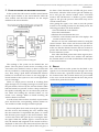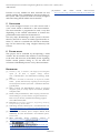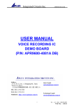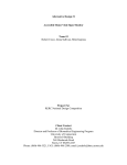
1
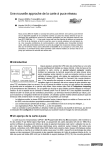
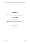
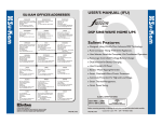
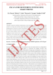
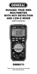
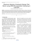
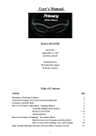
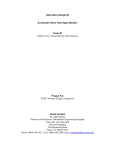
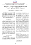
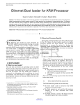
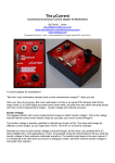
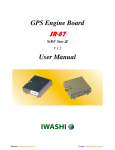
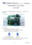
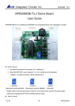
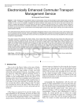
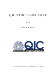
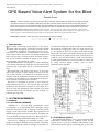
International Journal of Scientific & Engineering Research, Volume 2, Issue 1, January-2011
ISSN 2229-5518
GPS Based Voice Alert System for the Blind
Rishabh Gulati
Abstract— GPS is employed to find the position of the user on the earth. This information is provided by the GPS with the help
of the data it receives from the satellites. GPS based voice alert system for the blind uses the current location and gives the
alert to the blind man if it was his destination area. This paper describes the concept using a microcontroller based system. The
system has a dynamic user interface and is easily operable. The system is realised using a GPS module (SR-92) and a Voice
Module (APR9600) interfaced with a PIC16F877 microcontroller. The working of the system incorporates two stages; first the
location based audio recording stage and second, the navigation of the blind person using the signal from the GPS receiver. The
system employs a user friendly design and provides for an automatic location name announcement system.
Index Terms— Navigation, Audio input-output, User Interfaces, PIC microcontroller.
——————————
——————————
1 INTRODUCTION
T
he Global Positioning System (GPS) is a U.S. space-
based radio navigation system that provides reliable
positioning, navigation, and timing services to civilian users on a continuous worldwide basis. For anyone
with a GPS receiver, the system will provide location and
time. GPS provides accurate location and time information for an unlimited number of people in all weather,
day and night, anywhere in the world.
GPS based blind man device with user input interfacing
(voice based) intellectually finds the current location and
gives the alert to the blind man if it was his destination
area.
Microcontroller is the heart of the device. It stores the
data of the current location which it receives from the
GPS system, so that it can make use of the data stored to
compare with the destination location of the user. By this
it can trace out the distance from the destination and produce an alarm to alert the user in advance.
This device is designed to provide a voice based announcement for the user, i.e, the user gets the voice which
pronounces his destination location as and when he is
about to reach the destination. Here instead of an alarm
sound the blind man can directly hear the location recorded by the user itself.
tal sound recording time can be varied from 32 seconds to
60 seconds by changing the value of a single resistor. The
IC can operate in one of two modes: serial mode and parallel mode. In serial access mode, sound can be recorded
in 256 sections. In parallel access mode, sound can be recorded in 2, 4 or 8 sections. The IC can be controlled simply using push button keys. It is also possible to control the
IC using external digital circuitry such as microcontrollers and computers.
2 SYSTEM REQUIREMENTS
2.1 Hardware
2.1.1 Voice Module (APR9600)
APR9600 is a low-cost high performance sound
record/replay IC incorporating flash analogue storage
technique. Recorded sound is retained even after power
supply is removed from the module. The replayed sound
exhibits high quality with a low noise level. Sampling rate
for a 60 second recording period is 4.2 kHz that gives a
sound record/replay bandwidth of 20Hz to 2.1 kHz.
However, by changing an oscillation resistor, a sampling rate as high as 8.0 kHz can be achieved. This shortens the total length of sound recording to 32 seconds. To-
Figure1: circuit diagram of voice module
2.1.2 GPS Module (SR-92)
The GPS Module SR-92 is a low power and ultra-high
performance module which is perfectly suited for this
system. It has a 5 pin I/O interface. The module comes
with a GPIO control pin for controlling the power. This
IJSER © 2010
1
2
International Journal of Scientific & Engineering Research, Volume 2, Issue 1, January-2011
ISSN 2229-5518
module has an upgradeable Firmware for future potential
performance enhancements.
Specification:
General
Tracking sensitivity – “-159dBm”
Chipset - SiRF Star
Channels - 20 channel all-in-view tracking
Power
Power input - 3.3V
Power consumption at full tracking - 40mA
Interface
Update time - 1 second
NMEA output protocol - V.3.00
Baud rate - 4800 (default), 9600, 19200, 38400, 57600
Bps (8-N-1)
2.1.3 Microcontroller
The microcontroller used for this system is
PIC16F877A. The PIC families of microcontrollers are
developed by Microchip Technology Inc. Currently they
are some of the most popular microcontrollers, selling
over 120 million devices each year. There are basically
four families of PIC microcontrollers:
PIC12CXXX 12/14-bit program word
PIC16C5X 12-bit program word
PIC16CXXX and PIC16FXXX 14-bit program word
PIC17CXXX and PIC18CXXX 16-bit program word
Figure2: architecture of PIC microcontroller
2.1.3.2 Pin Description
PIC16F877 is a 40 pin microcontroller. It has 5 ports
port A, port B, port C, port D, port E. All the pins of the
ports are for interfacing input output devices.
Port A: It consists of 6 pins from A0 to A5
Port B: It consists of 8 pins from B0 to B7
Port C: It consists of 8 pins from C0 to C7
Port D: It consists of 8 pins from D0 to D7
Port E: It consists of 3 pins from E0 to E2
The rest of the pins are mandatory pins these should not
be used to connect input/output devices.
Pin 1 is MCLR (master clear pin) pin also referred as reset
pin.
Pin 13, 14 are used for connecting the crystal oscillator to
generate a frequency of about 20MHz.
2.1.3.1 Features
The CPU uses Harvard architecture with separate Program and Variable (data) memory interface. This facilitates instruction fetch and the operation on data/accessing
of variables simultaneously. Basically, all PIC microcontrollers offer the following features:
RISC instruction set
On-chip timer with 8-bit prescaler
Power-on reset
Watchdog timer
Power saving SLEEP mode
Direct, indirect, and relative addressing modes
External clock interface
RAM data memory
EPROM (or OTP) program memory
Some devices offer the following additional features:
Analogue input channels
Analogue comparators
Additional timer circuits
EEPROM data memory
Flash EEPROM program memory
External and timer interrupts
In-circuit programming
Internal oscillator
USART serial interface
Figure3: pin diagram for PIC16F877
IJSER © 2010
International Journal of Scientific & Engineering Research, Volume 2, Issue 1, January-2011
3
ISSN 2229-5518
2.1.4 Regulated Power Supply
A device or system that supplies electrical or other
types of energy to an output load or group of loads is
called a power supply unit or PSU. The term is most
commonly applied to electrical energy supplies, less often
to mechanical ones, and rarely to others.
A power supply may include a power distribution system as well as primary or secondary sources of energy
such as
Conversion of one form of electrical power to another
desired form and voltage, typically involving converting AC line voltage to a well-regulated lowervoltage DC for electronic devices. Low voltage, low
power DC power supply units are commonly integrated with the devices they supply, such
as computers and household electronics.
Batteries.
Chemical fuel cells and other forms of energy storage systems.
Solar power.
Generators/alternators.
Figure4: Regulated Power Supply
2.1.5 Micellaneous items
An LCD display is incorporated for a better user interface. Its primary use is to display the latitude and longitude of the current location.
Two different coloured LED’s for indicating the type of
data received from the GPS receiver.
A Speaker, for announcing the message’s, recorded using the voice module.
2.2 Software
2.2.1 Express PCB
This software is used for designing the circuit. Breadboards are great for prototyping equipment as it allows
great flexibility to modify a design when needed; however the final product of a project, ideally should have a
neat PCB, few cables, and survive a shake test. Not only is
a proper PCB neater but it is also more durable as there
are no cables which can yank loose.
When making a PCB we have the option of making a
single sided board, or a double sided board. Single sided
boards are cheaper to produce and easier to etch, but
much harder to design for large projects. If a lot of parts
are being used in a small space it may be difficult to make
a single sided board without jumpering over traces with a
cable. While there’s technically nothing wrong with this,
it should be avoided if the signal travelling over the traces
is sensitive (e.g. audio signals).
A double sided board is more expensive to produce
professionally, more difficult to etch on a DIY board, but
makes the layout of components a lot smaller and easier.
It should be noted that if a trace is running on the top
layer, check with the components to make sure you can
get to its pins with a soldering iron. Large capacitors, relays, and similar parts which don’t have axial leads can
NOT have traces on top unless boards are plated professionally.
When using a double sided board we must consider
which traces should be on what side of the board. Generally, we put power traces on the top of the board, jumping only to the bottom if a part cannot be soldered onto
the top plane (like a relay), and vice- versa.
2.2.2 PIC Compiler
PIC compiler is a software in which the machine language code is written and compiled. After compilation,
the machine source code is converted into hex code which
is to be dumped into the microcontroller for further
processing. PIC compiler also supports C language code.
It’s important that we know the C language for microcontrollers which is commonly known as Embedded C.
The PCB, PCM, and PCH are separate compilers. PCB is
for 12-bit opcodes, PCM is for 14-bit opcodes, and PCH is
for 16-bit opcode PIC microcontrollers. These compilers
are specifically designed to meet the unique needs of the
PIC microcontroller. When compared to a more traditional C compiler, PCB, PCM, and PCH have some limitations. One of the limitations being function recursion is
not allowed.
This is due to the fact that the PIC has no stack to push
variables onto, and also because of the way the compilers
optimize the code. The compilers can efficiently implement normal C constructs, input/output operations, and
bit twiddling operations. All normal C data types are
supported along with pointers to constant arrays, fixed
point decimal, and arrays of bits.
2.2.3 Proteus
Proteus is a software which accepts only hex files. Once
the machine code is converted into a hex code, that hex
code has to be dumped into the microcontroller and this
is done by Proteus. Proteus is a programmer which itself
contains a microcontroller in it other than the one which
is to be programmed. This microcontroller has a program
in it written in such a way that it accepts the hex file from
the PIC compiler and dumps this hex file into the microcontroller which is to be programmed.
The program which is to be dumped into the microcontroller is edited, compiled and executed. After the successful compilation of the program, it is dumped into the
microcontroller using a dumper.
IJSER © 2010
International Journal of Scientific & Engineering Research, Volume 2, Issue 1, January-2011
4
ISSN 2229-5518
3 VOICE RECORDING AND WORKING PROCEDURE
In this system, the GPS receiver and the control buttons
are the input modules to the microcontroller while the
Voice module and the LED indicators are the output
modules to the microcontroller.
Figure5: system block diagram
The working of the system can be divided into two
phases. The first phase would involve recording of the
voice in the voice module. For this, we have to switch ON
the voice module by connecting the power supply (batteries). Then, using a push button and different selection
buttons we record the voice. Since we are using eight selection buttons in this system we can record eight different voice messages.
There is a simple process involved in recording these
eight messages. For recording a message we need to press
the push button, followed by the selection button. While
both the buttons are pressed, we hear a beep sound from
the speaker, indicating that we can release the push button. While still holding the selection button, we can
record a 5sec message. When we finish recording, the
selection button is released.
In order to hear what we have recorded, we just need to
press and hold the corresponding selection button for
1sec and the recorded message would be replayed.
the data is Void data then the red LED will glow. Active
data means, when the GPS receiver gets the satellite signal it will give the current location values. Void data
means if the GPS Receiver is unable to get the satellite
signal it will give the previous data which may not be
current location value.
After getting the signal, if we want to store the present
location as an alerting location for the blind person, the
following procedure will do the needful –
i.Press and hold the control button
ii.Press the restart button
iii.Release the restart button after 1sec
iv.Hold the control button until the LCD displays ‘the
current location is saved’
Like this we can store 3 different locations by using the
control buttons. These values will be stored into the EEPROM which is a non-volatile memory. We just have to
make sure that the distance between the two locations is
greater than 100 meters. After storing the location(s), we
need to restart the system.
Now when the blind person enters these regions (locations) with this system the voice module will announce
the location names as we had recorded them with respect
to the stored locations.
4 RESULT
The “GPS based voice alert system for the blind” is designed so as to alert the blind person through voice alerts
when he enters into a particular location by announcing
the location name. The locations names are pre recorded
in the voice circuit and are announced when the person
reaches those particular locations.
The second phase deals with receiving the signal from
the GPS receiver and actuating the voice module using
the microcontroller. To implement this phase, we switch
ON the main power supply to the microcontroller. Next,
we show the GPS to the open sky for receiving the satellite signal. When the satellite signal is receieved by the
GPS, the latitude and longitude of the current location is
displayed on the LCD. If the data received from the GPS
receiver is Active data then the yellow LED will glow, if
IJSER © 2010
Figure6: successful program dumping using PICkit 2
International Journal of Scientific & Engineering Research, Volume 2, Issue 1, January-2011
5
ISSN 2229-5518
Presence of every module has been reasoned out and
placed carefully, thus contributing to the best working of
the system. This system has been successfully designed
and tested using the PIC16F877 microcontroller.
[10] 28/40-Pin
8-Bit
CMOS
FLASH
Microcontrollers
http://ww1.microchip.com/downloads/en/devicedoc/30292c.pdf
5 CONCLUSION
The system designed consists of a GPS receiver and a
voice circuit which is interfaced to the microcontroller.
The microcontroller is programmed in such a way that
depending on the satellite information of location the
predefined location name will be announced.
The only major disadvantage of this system is the time
taken by the GPS to receive its initial signal from the satellite, i.e, when it is switched ON. The above disadvantage can be removed by using a higher efficiency GPS
receiver.
6 FUTURE SCOPE
This project can be extended by incorporating a GSM
module. We can interface this module to send messages
to the near and dear ones of the Blind person regarding
his/her current position. Doing so, we can track the
movement of the Blind person in a very efficient manner.
REFERENCES
[1]
[2]
[3]
[4]
Punwilai, J. Noji, T. Kitamura, “The design of a voice navigation
system for the blind in Negative Feelings Environment”, Communications and Information Technology, ISCIT
2009.
Kaminski, L. Kowalik, R. Lubniewski, Z. Stepnowski, “VOICE
MAPS — portable, dedicated GIS for supporting the street navigation
and self-dependent movement of the blind ”, Information Technology (ICIT), 2010.
Helal, A. Moore, S.E. Ramachandran, “Drishti: an integrated
navigation system for visually impaired and disabled”, Wearable
Computers, 2001.
Marsh, A. May, M. Saarelainen, “Pharos: coupling GSM and GPSTALK technologies to provide orientation, navigation and locationbased services for the blind”, Information Technology Applications in Biomedicine, 2000.
[5]
[6]
[7]
[8]
[9]
Raj kamal, Microcontrollers: Architecture, Programming, Interfacing
and System Design, Prentice Hall.
PCB Design Tutorial, David.L.Jones, www.alternatezone.com,
http://www.alternatezone.com/electronics/files/PCBDesignTuto
rialRevA.pdf
Muhammad Ali Mazidi, Janice Gillispie Mazidi, Rolin
D.Mckinlay, the 8051 Microcontroller and Embedded Systems,
Prentice Hall.
SR-92
Data-sheet
Progin
technology
Version
1.0
http://www.seeedstudio.com/depot/images/product/sr-92.pdf
Digitally signed by Editor IJSER
APR9600 Single-Chip Voice
Playback Device 60DN: Recording
cn=Editor IJSER,&
c=FR,
o=IJSER, ou=IJSER,
Second Duration user manual
[email protected]
Reason: I attest to the accuracy
http://www.aplusinc.com.tw/data/apr9600_mod3-english.pdf
and integrity of this document
Date: 2011.02.26 16:16:03
+05'30'
http://www.datasheetcatalog.org/datasheet/aplus/APR9600.pdf
Editor
IJSER
IJSER © 2010