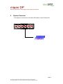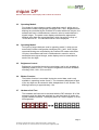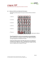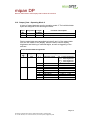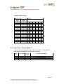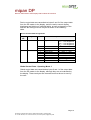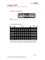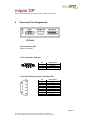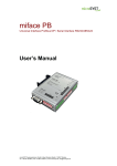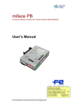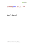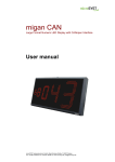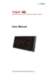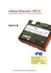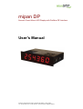
1
mipan DP
Numeric Panel-Mount LED Display with Profibus-DP Interface
User's Manual
microSYST Systemelectronic GmbH, Albert-Einstein-Straße 7, 92637 Weiden
Tel. +49 961 39166-0, Fax +49 961 39166-10, www.microsyst.de, [email protected]
mipan DP
Numeric Panel-Mount LED Display with Profibus-DP Interface
Table of Contents
1
GENERAL
4
1.1
4
Special Features
2
SYSTEM OVERVIEW
5
3
TECHNICAL DATA
6
3.1
Operating Modes
6
3.2
Operating Mode 1
6
3.3
Operating Mode 2
7
3.4
Operating Mode 3
7
3.5
Brightness Control
7
3.6
Blinker Function
7
3.7
Hardware Self-Test
7
3.8
Software Self-Test and Start-Up Performance
8
3.9
Monitoring the Profibus DP Interface
9
3.10 LED Test
9
3.11 Hardware Malfunction Display
9
3.12 Profibus DP Characteristic Data
10
3.13 Config_Data - Operating Mode 1
11
3.14 Config_Data - Operating Mode 2
11
3.15 Config_Data - Operating Mode 3
11
3.16 User Parameter Data - User_Prm_Data
11
3.17 Output_Data - Operating Mode 1
12
3.18 Output_Data - Operating Mode 2
13
3.19 Output_Data - Operating Mode 3
14
Page 2
microSYST Systemelectronic GmbH, Albert-Einstein-Straße 7, 92637 Weiden
Tel. +49 961 39166-0, Fax +49 961 39166-10, www.microsyst.de, [email protected]
mipan DP
Numeric Panel-Mount LED Display with Profibus-DP Interface
4
5
6
CONNECTOR PIN ASSIGNMENTS
17
4.1
Display Elements
19
HOUSING DIMENSIONS
20
5.1
20
Panel Cutout
APPENDIX
21
6.1
Standard Equipment
21
6.2
Maintenance and Care
21
6.3
Troubleshooting, General Problems
22
6.4
Declaration of Conformity
23
6.5
Warranty / Liability
24
6.6
Versions Overview
25
Page 3
microSYST Systemelectronic GmbH, Albert-Einstein-Straße 7, 92637 Weiden
Tel. +49 961 39166-0, Fax +49 961 39166-10, www.microsyst.de, [email protected]
mipan DP
Numeric Panel-Mount LED Display with Profibus-DP Interface
1
General
There's no doubt that Profibus is becoming more and more significant
with the ever growing number of devices which are equipped with a
Profibus interface.
The numeric panel mount LED display with Profibus interface is a high
performance product which has been especially designed for industrial
use.
The metal housing and rugged design of the numeric panel mount LED
display with Profibus interface make it ideal for all type of applications,
even under adverse ambient conditions.
1.1
Special Features
The display has been designed for use as a data converter between a
Profibus DP master and a 6 digit, 7 segment display. It functions as a
slave module at the Profibus DP, and allows for the display of data.
Various functions are made available depending upon configuration (2
bytes output data for operating mode 1, 4 bytes output data for operating mode 2, 10 bytes output data for operating mode 3). For example,
display brightness can be adjusted by means of control data, and/or individual characters can be caused to blink independent of one another.
The device is equipped with the following important functional features:
•
•
•
•
•
•
Profibus DP configuration with three different operating modes
Brightness can be set to 4 different levels
Blinker function for each of the 6 display digits at approx. 1 Hz
Conversion of integer values with preceding plus or minus sign
Individual display digits can be driven directly
Self-test function via control bit from Profibus DP data, or with DIP
switches
• Self-test function with DIP switches
• LED test with 24 VDC external
• Error message indicates interruption of communications via the
Profibus DP.
Page 4
microSYST Systemelectronic GmbH, Albert-Einstein-Straße 7, 92637 Weiden
Tel. +49 961 39166-0, Fax +49 961 39166-10, www.microsyst.de, [email protected]
mipan DP
Numeric Panel-Mount LED Display with Profibus-DP Interface
2
System Overview
The display is connected to a Profibus DP master via the Profibus DP.
Page 5
microSYST Systemelectronic GmbH, Albert-Einstein-Straße 7, 92637 Weiden
Tel. +49 961 39166-0, Fax +49 961 39166-10, www.microsyst.de, [email protected]
mipan DP
Numeric Panel-Mount LED Display with Profibus-DP Interface
3
Technical Data
General Specifications
Display type:
Character height:
Digits:
Display colour:
Operating voltage:
Power consumption
Red displays:
Green displays:
Addresses:
Interface:
Display:
Baud rate:
Housing:
7 segment LED
13 mm
6 digits
red, green
24 VDC ±20 %
approx. 75 mA at 24 VDC operating voltage
approx. 100 mA at 24 VDC operating voltage
0 to 126
Profibus-DP
0 to 9 and H, E, L, P, -, Blank
9.6 KBaud to 12 MBaud
DIN panel-mount housing, metal with special
surface finish
Housing dimensions:
see chapter 5
Mounting:
screw clamps
Protection:
front panel IP 65
Weight:
approx. 270 grams
Operating temperature: 0 to +50° C
Storage temperature: -25 to +70° C
3.1
Operating Modes
Three different operating modes with various functions are available for
the display. The operating mode is selected with the configuration data.
3.2
Operating Mode 1
Two bytes of output data are used in operating mode 1, which are selected with Profibus configuration identifier 0x21. These 2 bytes can be
used to transmit a numeric value as a signed integer from the Profibus
DP master. The panel mount display calculates the appropriate decimal
value from the transmitted data, which lies within a range of -32768 and
32767. The calculated value is then displayed.
Page 6
microSYST Systemelectronic GmbH, Albert-Einstein-Straße 7, 92637 Weiden
Tel. +49 961 39166-0, Fax +49 961 39166-10, www.microsyst.de, [email protected]
mipan DP
Numeric Panel-Mount LED Display with Profibus-DP Interface
3.3
Operating Mode 2
Four bytes of output data are used in operating mode 2, which are selected with Profibus configuration identifiers 0x21, 0x21. Brightness and
blinking are controlled by the Profibus DP master with these 4 bytes, the
software self-test is initialized and a numeric value is transmitted as a
signed integer. The panel mount display calculates the appropriate
decimal value from the transmitted data, which lies within a range of
-32768 and 32767. The calculated value is then displayed.
3.4
Operating Mode 3
Ten bytes of output data are used in operating mode 3, which are selected with Profibus configuration identifiers 0x21, 0x21, 0x25. Brightness and blinking are controlled by the Profibus DP master with these
10 bytes, the software self-test is initialized and a numeric value is
transmitted as a signed integer, and a display value is transmitted for
each of the six digits.
3.5
Brightness Control
Brightness is controlled via device control data, and is only available in
operating modes 2 and 3. Four different brightness levels are available
including 100%, 80%, 50% and 20%.
3.6
Blinker Function
The blinker function is controlled via device control data, and is only
available in operating modes 2 and 3. The characters displayed at each
of the six digits can be caused to blink independent of one another. The
blinking frequency is approximately 1 Hz.
3.7
Hardware Self-Test
The hardware self-test can be activated with the DIP switches. All of the
segments at all six digits are switched on, and then back off again, during the hardware self-test. The display blinks at a rate of approx. 2 Hz at
full brightness.
Page 7
microSYST Systemelectronic GmbH, Albert-Einstein-Straße 7, 92637 Weiden
Tel. +49 961 39166-0, Fax +49 961 39166-10, www.microsyst.de, [email protected]
mipan DP
Numeric Panel-Mount LED Display with Profibus-DP Interface
3.8
Software Self-Test and Start-Up Performance
The following displays appear during the software self-test and device
start-up:
1st Second
2nd Second
3rd Second
4th Second
5th Second
6th Second
Displaying the address
The software self-test is performed automatically each time operating
power is switched on, or can be run continuously in operating modes 2
and 3 in which case it is initialized via device control data by setting the
corresponding bits at the Profibus DP master.
During the software self-test immediately after start-up, the display is illuminated at full brightness (100%). The brightness level selected with
the control data is taken into consideration during the software self-test
which is initialized by the Profibus DP master.
Page 8
microSYST Systemelectronic GmbH, Albert-Einstein-Straße 7, 92637 Weiden
Tel. +49 961 39166-0, Fax +49 961 39166-10, www.microsyst.de, [email protected]
mipan DP
Numeric Panel-Mount LED Display with Profibus-DP Interface
3.9
Monitoring the Profibus DP Interface
The Profibus DP interface is monitored by the panel mount LED display
if the watchdog for the slave has been activated by the Profibus DP
master. If no Profibus DP connection can be established, or if the connection to the master is interrupted, the following sequence appears at
the display.
The status of the Profibus DP interface is also indicated at the LED
monitor.
3.10 LED Test
The LED test function can be activated at pin 2 of the 3-pole terminal
connector. As soon as +24 VDC are applied to this terminal, all display
segments are illuminated at full brightness.
3.11 Hardware Malfunction Display
If a hardware error is detected during start-up, six static hyphens appear
at the display. As a rule, this indicates that the blinker function is inactive
for the RUN LED.
Page 9
microSYST Systemelectronic GmbH, Albert-Einstein-Straße 7, 92637 Weiden
Tel. +49 961 39166-0, Fax +49 961 39166-10, www.microsyst.de, [email protected]
mipan DP
Numeric Panel-Mount LED Display with Profibus-DP Interface
3.12 Profibus DP Characteristic Data
ID Number:
0x04D0
Maximum Output Data:
2 bytes DP output data: operating mode 1
4 bytes DP output data: operating mode 2
10 bytes DP output data: operating mode 3
Default Configuration:
0x21, 0x21, 0x25
Parameter Data:
7 bytes, default
User PRM:
none
Diagnosis:
6 bytes, default
External Diagnosis:
none
Baud Rate:
9.6 KBaud / 19.2 KBaud / 93.75 KBaud /
187.5 KBaud / 500 KBaud / 1.5 MBaud /
3 MBaud / 6 MBaud / 12 MBaud
Protocol:
Profibus DP, DIN 19245, Part 3
Device Database File:
MIPN04D0.GSD
Configuration of the display is performed with 1, 2 or 3 bytes of configuration data. The display's operating mode is also selected by means of
configuration data. The interface receives and examines the transmitted
configuration data, which must conform to one of the possibilities shown
in the tables below. If incorrect configuration data are transmitted to the
interface as regards number of bytes or identifier, Profibus initialization
is disabled and the slave's parameters must be reconfigured.
Page 10
microSYST Systemelectronic GmbH, Albert-Einstein-Straße 7, 92637 Weiden
Tel. +49 961 39166-0, Fax +49 961 39166-10, www.microsyst.de, [email protected]
mipan DP
Numeric Panel-Mount LED Display with Profibus-DP Interface
3.13 Config_Data - Operating Mode 1
2 bytes of DP output data and 0 bytes input data are used for operating
mode 1.
Byte
No.
Data (Iden- Output
tifier)
Data
Function / Description
0
0x21
output data: display data as signed integer
2
3.14 Config_Data - Operating Mode 2
4 bytes of DP output data and 0 bytes input data are used for operating
mode 2.
Byte
No.
Data (Identifier)
Output
Data
Function / Description
0
1
0x21
0x21
2
2
output data: device control data
output data: display data as signed integer
3.15 Config_Data - Operating Mode 3
10 bytes of DP output data and 0 bytes input data are used for operating
mode 3.
Byte
No.
Data (Identifier)
Output
Data
Function / Description
0
1
2
0x21
0x21
0x25
2
2
6
output data: global control data (reserved)
output data: device control data
output data: display data as display value
3.16 User Parameter Data - User_Prm_Data
The user parameter data are not used by the display. However, a test is
run to make sure that no user parameter data have been configured by
the Profibus master. If parameter data have been configured, Profibus
initialization is disabled and the slave's parameters must be reconfigured.
Page 11
microSYST Systemelectronic GmbH, Albert-Einstein-Straße 7, 92637 Weiden
Tel. +49 961 39166-0, Fax +49 961 39166-10, www.microsyst.de, [email protected]
mipan DP
Numeric Panel-Mount LED Display with Profibus-DP Interface
3.17 Output_Data - Operating Mode 1
2 bytes of output data are used in operating mode 1. The individual data
bytes are assigned to the following functions:
Byte
No.
0-1
Designation
Data
Length in
Bytes
2
Function / Description
display data as signed integer
The numeric value to be displayed is transmitted as a signed integer via
2 bytes of output data.
Display Value Coding:
Output_Data
Byte 0
Byte 1
(HEX)
(HEX)
00
00
00
01
00
02
00
03
↓
↓
7F
FD
7F
FE
7F
FF
80
00
80
01
80
02
↓
↓
FF
FD
FF
FE
FF
FF
Display
0
1
2
3
-
3
3
3
3
3
3
2
2
2
2
2
2
7
7
7
7
7
7
-
6
6
6
6
6
6
5
6
7
8
7
6
3
2
1
Page 12
microSYST Systemelectronic GmbH, Albert-Einstein-Straße 7, 92637 Weiden
Tel. +49 961 39166-0, Fax +49 961 39166-10, www.microsyst.de, [email protected]
mipan DP
Numeric Panel-Mount LED Display with Profibus-DP Interface
3.18 Output_Data - Operating Mode 2
4 bytes of output data are used in operating mode 2. The individual data
bytes are assigned to the following functions:
Byte
No.
0-1
2-3
Designation
Strb
Data
Length
in Bytes
2
2
Function / Description
device control data
display data as signed integer
Device control data are transmitted as bytes 0 and 1 of the output data
from the DP master to the display, and are used to control display
brightness and blinking of individual digits, as well as triggering of the
self-test.
Device Control Data Assignments
Byte
No.
0
1
Designation Bit No. Function / Description
Strb
Strb
0-1
brightness control
2
3-7
0
1
2
3
4
5
6-7
software self-test
no function
digit 1 blinks
digit 2 blinks
digit 3 blinks
digit 4 blinks
digit 5 blinks
digit 6 blinks
no function
00B = 100% brightness
01B = 80% brightness
10B = 50% brightness
11B = 20% brightness
0B = OFF, 1B = ON
0B = OFF, 1B = ON
0B = OFF, 1B = ON
0B = OFF, 1B = ON
0B = OFF, 1B = ON
0B = OFF, 1B = ON
0B = OFF, 1B = ON
Page 13
microSYST Systemelectronic GmbH, Albert-Einstein-Straße 7, 92637 Weiden
Tel. +49 961 39166-0, Fax +49 961 39166-10, www.microsyst.de, [email protected]
mipan DP
Numeric Panel-Mount LED Display with Profibus-DP Interface
Display Value Coding:
Output_Data
Byte 0
Byte 1
(HEX)
(HEX)
00
00
00
01
00
02
00
03
↓
↓
7F
FD
7F
FE
7F
FF
80
00
80
01
80
02
↓
↓
FF
FD
FF
FE
FF
FF
Display
0
1
2
3
-
3
3
3
3
3
3
2
2
2
2
2
2
7
7
7
7
7
7
-
6
6
6
6
6
6
5
6
7
8
7
6
3
2
1
3.19 Output_Data - Operating Mode 3
10 bytes of output data are used in operating mode 3. The individual
data bytes are assigned to the following functions:
Byte
No.
0-1
2-3
4-9
Designation
Header
Strb
Data
Length
in Bytes
2
2
6
Function / Description
global control data (reserved)
device control data
display data (coded)
Page 14
microSYST Systemelectronic GmbH, Albert-Einstein-Straße 7, 92637 Weiden
Tel. +49 961 39166-0, Fax +49 961 39166-10, www.microsyst.de, [email protected]
mipan DP
Numeric Panel-Mount LED Display with Profibus-DP Interface
Device control data are transmitted as bytes 2 and 3 of the output data
from the DP master to the display, and are used to control display
brightness and blinking of individual digits, as well as triggering of the
self-test. Bit coding for these 2 bytes is shown in the following
table:
Device Control Data Assignments
Byte
No.
2
3
Designation
Strb
Strb
Bit No. Function / Description
0-1
brightness control
2
3-7
0
1
2
3
4
5
6-7
software self-test
no function
digit 1 blinks
digit 2 blinks
digit 3 blinks
digit 4 blinks
digit 5 blinks
digit 6 blinks
no function
00B = 100% brightness
01B = 80% brightness
10B = 50% brightness
11B = 20% brightness
0B = OFF, 1B = ON
0B = OFF, 1B = ON
0B = OFF, 1B = ON
0B = OFF, 1B = ON
0B = OFF, 1B = ON
0B = OFF, 1B = ON
0B = OFF, 1B = ON
Global Control Data - Operating Mode 3
Global control data are transmitted as bytes 0 and 1 of the output data
from the DP master to the display, although they are not evaluated by
the display. These two bytes are reserved and must be set to zero by
the user.
Page 15
microSYST Systemelectronic GmbH, Albert-Einstein-Straße 7, 92637 Weiden
Tel. +49 961 39166-0, Fax +49 961 39166-10, www.microsyst.de, [email protected]
mipan DP
Numeric Panel-Mount LED Display with Profibus-DP Interface
Display Data - Operating Mode 3
Digit:
Output Data, Byte No.:
6
4
5
5
4
6
3
7
2
8
1
9
List of Displayable Characters
Code in
HEX
0x00
0x01
0x02
0x03
0x04
0x05
0x06
0x07
0x08
0x09
0x0A
0x0B
0x0C
0x0D
0x0E
0x0F
7
0
0
0
0
0
0
0
0
0
0
0
0
0
0
0
0
6
x
x
x
x
x
x
x
x
x
x
x
x
x
x
x
x
5
x
x
x
x
x
x
x
x
x
x
x
x
x
x
x
x
Binary Code
Bit No.:
4
3
x
0
x
0
x
0
x
0
x
0
x
0
x
0
x
0
x
1
x
1
x
1
x
1
x
1
x
1
x
1
x
1
Displayed
Character
2
0
0
0
0
1
1
1
1
0
0
0
0
1
1
1
1
1
0
0
1
1
0
0
1
1
0
0
1
1
0
0
1
1
0
0
1
0
1
0
1
0
1
0
1
0
1
0
1
0
1
0
1
2
3
4
5
6
7
8
9
E
H
L
P
"blank"
x = is not evaluated
A decimal point is entered after the corresponding character by setting bit
number 7. However, this function is only available in operating mode 3.
Page 16
microSYST Systemelectronic GmbH, Albert-Einstein-Straße 7, 92637 Weiden
Tel. +49 961 39166-0, Fax +49 961 39166-10, www.microsyst.de, [email protected]
mipan DP
Numeric Panel-Mount LED Display with Profibus-DP Interface
4
Connector Pin Assignments
Flat Connector (PE)
Earth connection.
3 Pin Connector Terminal
Pin
1
2
3
Assignment
+24 VDC
LED test
GND
9 Pin Sub-D Plug Connector (Profibus DP)
Pin
1
2
3
4
5
6
7
8
9
Assignment
Shield
free
Rx+
RTS signal
GND
+5 VDC
n.c.
Rxn.c.
Page 17
microSYST Systemelectronic GmbH, Albert-Einstein-Straße 7, 92637 Weiden
Tel. +49 961 39166-0, Fax +49 961 39166-10, www.microsyst.de, [email protected]
mipan DP
Numeric Panel-Mount LED Display with Profibus-DP Interface
LED Monitor (Bottom of Housing)
LED
Colour
RUN
Green
INTERNAL
Red
BUS
Yellow
Function
Start-Up:
Normal Operation:
Error:
Start-Up:
Normal Operation:
Error:
Start-Up:
Normal Operation:
Profibus DP active
Profibus DP inactive
Off
blinks at approx. 2 Hz
lit continuously, off
On
On
blinks at approx. 1 Hz, off
Off
On
Off
DIP Switch
DIP Switches, DIP1
Profibus DP Address
DIP 8
DIP 7
DIP 6
DIP 5
DIP 4
DIP 3
DIP 2
Operating Mode
DIP 1
Profibus DP Address / Operating Mode
0
ID No.: 2
1
ID No.: 2
2
ID No.: 2
3
ID No.: 2
4
ID No.: 2
5
ID No.: 2
6
ID No.: 2
Normal Operation /
Self-Test
ON
1D
2D
4D
8D
16 D
32 D
64D
ON
Self-Test
OFF
0
0
0
0
0
0
0
OFF
Normal
Operation
Bus Termination (Bottom of Housing)
The bus termination of the Profibus-DP interface is activated by switching on both DIP switches (position ON).
Page 18
microSYST Systemelectronic GmbH, Albert-Einstein-Straße 7, 92637 Weiden
Tel. +49 961 39166-0, Fax +49 961 39166-10, www.microsyst.de, [email protected]
mipan DP
Numeric Panel-Mount LED Display with Profibus-DP Interface
4.1
Display Elements
The digits are designated from left to right as shown above.
Component
6 Digit 7 Segment Display
Number of lines:
Characters per line:
Character height:
Display colour:
Brightness:
Display type:
Function / Description
1
6
13 mm
red or green illuminated
4 levels (20%, 50%, 80%, 100%)
7 segment
Page 19
microSYST Systemelectronic GmbH, Albert-Einstein-Straße 7, 92637 Weiden
Tel. +49 961 39166-0, Fax +49 961 39166-10, www.microsyst.de, [email protected]
mipan DP
Numeric Panel-Mount LED Display with Profibus-DP Interface
5
Housing Dimensions
Dimension
Measurement
(mm)
5.1
B
H
T
D
E
G
96
24
60
92
20
13
Panel Cutout
22.2 +0.3
R 0.8 max.
min. 10
22.2 +0.3
R 0.8 max.
93.0 +0.8
Page 20
microSYST Systemelectronic GmbH, Albert-Einstein-Straße 7, 92637 Weiden
Tel. +49 961 39166-0, Fax +49 961 39166-10, www.microsyst.de, [email protected]
mipan DP
Numeric Panel-Mount LED Display with Profibus-DP Interface
6
Appendix
6.1
Standard Equipment
•
•
•
•
•
6.2
Display with current software and hardware versions
Mounting materials
Mating plug for power supply
User's manual
Floppy disc with GSD file for original purchaser.
Maintenance and Care
Observe the following instructions in order to assure best possible performance of the display unit:
•
The display must be switched off before cleaning. Only solvent-free
cleaners may be used, as the surface of the housing may otherwise
be damaged. Under no circumstances may moisture be allowed to
enter the interior of the device during cleaning.
•
Protect the panel mount LED display from excessive humidity, extreme vibration, direct sunlight and extreme temperatures. Nonobservance may lead to malfunctioning or destruction of the device.
Under certain circumstances electrical shock, fire and explosion
may occur as well. Information concerning allowable ambient conditions, including recommended temperature and atmospheric humidity ranges, can be found in the chapter entitled "Technical Data".
•
The display may not be placed into service if the device and/or the
power cable are known to be damaged.
•
Do not attempt to open or repair the device yourself. The guarantee
is rendered null and void if the device is tampered with by unauthorized persons.
•
Observe all of the instructions and requirements which are included
in this user's manual.
Page 21
microSYST Systemelectronic GmbH, Albert-Einstein-Straße 7, 92637 Weiden
Tel. +49 961 39166-0, Fax +49 961 39166-10, www.microsyst.de, [email protected]
mipan DP
Numeric Panel-Mount LED Display with Profibus-DP Interface
6.3
Troubleshooting, General Problems
Problem
LED RUN does not blink
after start-up.
LED INTERNAL blinks.
Cause
No power or incorrect supply voltage
Defective device
Error during RAM
test, or internal
error
Solution
Use only the specified supply
voltage.
Return device for repair.
Switch supply power off and
then back on. If the problem
persists, return device for repair.
Troubleshooting, Display Problems
Problem
Only hyphens appear at
the display.
Cause
Internal error
Solution
Switch supply power off and
then back on. If the problem
persists, return device for
repair.
Set DIP switches to normal
operation.
Select a different brightness
setting via the
Profibus DP.
Check the Profibus.
All display segments
blink.
Display is barely legible.
Hardware test is
activated
Incorrect brightness
setting
Only "Es" appear at the
display.
Interface does not
respond.
No communication
via the Profibus DP
Configuration and/or Correct configuration and/or
parameters are inparameters.
correct
Troubleshooting, Profibus DP Problems
Problem
Interface does not
respond.
Cause
Pin assignments at
Profibus connector
are
incorrect (data
strands are reversed)
No bus termination,
or bus termination is
incorrect
Solution
Correct the pin assignments
at the Profibus
connector.
Correct the bus termination.
Page 22
microSYST Systemelectronic GmbH, Albert-Einstein-Straße 7, 92637 Weiden
Tel. +49 961 39166-0, Fax +49 961 39166-10, www.microsyst.de, [email protected]
mipan DP
Numeric Panel-Mount LED Display with Profibus-DP Interface
6.4
Declaration of Conformity
EG-Konformitätserklärung
Declaration of EC-Conformity
Produktbezeichnung:
mipan DP
Product name:
Produktbeschreibung:
Product description:
Numerische LED-Einbauanzeige mit Profibus-DP-Interface
Numeric Panel-Mount LED Display with Profibus-DP-Interface
Hersteller:
Manufacturer:
microSYST Systemelectronic GmbH
Albert-Einstein-Straße 7
92637 Weiden
Das bezeichnete Produkt stimmt mit
der folgenden Europäischen Richtlinie
überein:
We herewith confirm that the above mentioned product meets the requirements of
the following standard:
Die Übereinstimmung des bezeichneten
Produktes mit den Vorschriften der Richtlinie wird nachgewiesen durch die vollständige Einhaltung folgender Normen:
The correspondence of the above mentioned
product with these requirements is proved by
the fact that these products meet with the following single standards:
Nummer
Europäische Norm
EN61000-6-2:2006
EN61000-6-4:2007
2004/108/EG
Bezeichnung
Elektromagnetische
Verträglichkeit (EMV)
Weiden, den 13.03.2013
Harald Kilian
Leiter operatives Geschäft / COO
Prokurist / Authorized Signatory
Page 23
microSYST Systemelectronic GmbH, Albert-Einstein-Straße 7, 92637 Weiden
Tel. +49 961 39166-0, Fax +49 961 39166-10, www.microsyst.de, [email protected]
mipan DP
Numeric Panel-Mount LED Display with Profibus-DP Interface
6.5
Warranty / Liability
For the product, liability is assumed for defects, which existed at the delivery date according to our General Terms and Conditions.
Technically changes as well as errors are excepted. A claim for delivery
of a new product does not exist. The buyer has to check the received
product immediately and indicate evident defects at the latest 24 hours
after detection. Non-observance of notification requirements is equated
with acceptance of the defect. Not immediately visible defects have to
be indicated immediately after their perception too.
Generally, defects and their symptoms must be described as accurately
as possible in order to allow for reproducibility and elimination. The
buyer must provide for access to the relevant device and all required
and/or useful information at no charge and must make all of the required
data and machine time available free of charge.
The guarantee does not cover defects, which result from nonobservance of the prescribed conditions of use, or from improper handling.
If the device has been placed at the disposal of the buyer for test purposes and has been purchased subsequent to such testing, both parties
agree that the product is to be considered “used” and that it has been
purchased “as is”. No guarantee claims may be made in such cases.
The General Terms and Conditions of microSYST Systemelectronic
GmbH in current version apply as well.
Page 24
microSYST Systemelectronic GmbH, Albert-Einstein-Straße 7, 92637 Weiden
Tel. +49 961 39166-0, Fax +49 961 39166-10, www.microsyst.de, [email protected]
mipan DP
Numeric Panel-Mount LED Display with Profibus-DP Interface
6.6
Versions Overview
Version
Date
1.00
1.10
1.20
1.30
1.40
1.50
26.11.04
24.02.05
28.02.05
21.05.08
18.03.13
22.10.13
Comments, Description
Kreuzer: Document created
Kreuzer: Output_Data - Operating Mode 3 changed
Kreuzer: Power consumption; differences between red / green
Kreuzer: Housing depth changed to 60 mm
Declaration of conformity, warranty / liability changed
Logo
Certified per DIN EN ISO 9001.
Page 25
microSYST Systemelectronic GmbH, Albert-Einstein-Straße 7, 92637 Weiden
Tel. +49 961 39166-0, Fax +49 961 39166-10, www.microsyst.de, [email protected]