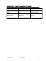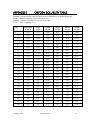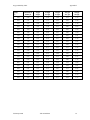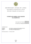
1
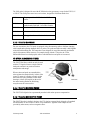
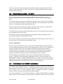
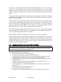
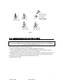
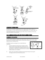
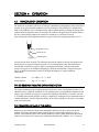
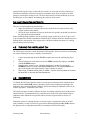
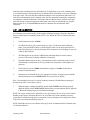
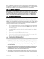
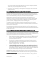
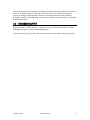
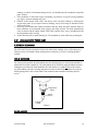
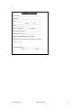
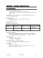
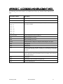
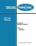
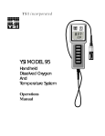
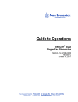
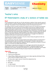
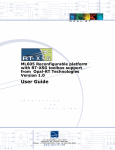
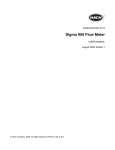
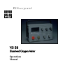
YSI 58
Dissolved Oxygen Meter
Operations
Manual
CONTENTS
SECTION 1
INTRODUCTION ....................................................................................................................... 1
SECTION 2
PREPARING THE METER...................................................................................................... 2
2.1 UNPACKING .............................................................................................................................................. 2
2.2 WARRANTY CARD .................................................................................................................................. 2
2.3 BATTERIES................................................................................................................................................. 2
SECTION 3
PREPARING THE PROBE....................................................................................................... 3
3.1 CHOOSING THE CORRECT PROBE...................................................................................................... 3
3.1.1 YSI 5239 DO FIELD PROBE ........................................................................................................... 3
3.1.2 YSI 5905 BOD PROBE ..................................................................................................................... 3
3.1.3 YSI 5739 DO PROBE ........................................................................................................................ 4
3.1.4 YSI 5718 DO FIELD PROBE ........................................................................................................... 4
3.1.5 YSI 5750 BOD BOTTLE PROBE .................................................................................................... 4
3.2 PROBE INSTALLATION - YSI 5739....................................................................................................... 5
3.3 CHOOSING THE CORRECT MEMBRANE........................................................................................... 5
3.3.1 MEMBRANE INSTALLATION FOR THE 5239 PROBE ............................................................ 6
3.3.2 MEMBRANE INSTALLATION FOR THE 5905 PROBE ............................................................ 7
3.3.3 MEMBRANE INSTALLATION FOR THE 5700-SERIES PROBES........................................... 8
SECTION 4
OPERATION.............................................................................................................................. 10
4.1 PRINCIPLES OF OPERATION............................................................................................................... 10
4.2 TURNING THE INSTRUMENT ON ...................................................................................................... 11
4.3 CALIBRATION......................................................................................................................................... 11
4.3.1 AIR CALIBRATION ....................................................................................................................... 12
4.3.2 WINKLER TITRATION ................................................................................................................. 13
4.3.3 AIR-SATURATED WATER CALIBRATION ............................................................................. 13
4.3.4 CALIBRATION FREQUENCY ..................................................................................................... 14
4.4 MAKING MEASUREMENTS................................................................................................................. 14
4.4.1 ENVIRONMENTAL CONSIDERATIONS .................................................................................. 14
4.4.2 MEASURING OXYGEN IN FLUIDS OTHER THAN WATER................................................ 15
4.4.3 CALIBRATING TO DISPLAY OXYGEN PARTIAL PRESSURE IN MM HG....................... 15
4.5 RECORDER OUTPUT ............................................................................................................................. 16
SECTION 5
CARE AND MAINTENANCE................................................................................................ 17
5.1 THE METER CASE .................................................................................................................................. 17
5.2 PROBE PERFORMANCE CHECK......................................................................................................... 17
5.3 PROBE PRECAUTIONS.......................................................................................................................... 17
5.3.1 5905 AND 5239 PROBE CARE ..................................................................................................... 18
5.3.2 5700-SERIES PROBE CARE.......................................................................................................... 19
5.4 PROBE STORAGE ................................................................................................................................... 19
5.4.1 5905 AND 5239 PROBE STORAGE ............................................................................................. 19
5.4.2 5700 SERIES PROBE STORAGE.................................................................................................. 19
SECTION 6
DISCUSSION OF MEASUREMENT ERRORS.................................................................. 20
SECTION 7
TROUBLESHOOTING............................................................................................................ 21
SECTION 8
WARRANTY AND SERVICE INFORMATION ................................................................ 23
APPENDIX A
GENERAL SPECIFICATIONS ......................................................................................... 28
i
APPENDIX B
REQUIRED NOTICE ......................................................................................................... 30
APPENDIX C
ACCESSORIES AND REPLACEMENT PARTS........................................................... 31
APPENDIX D
UNIT CONVERSION CHART .......................................................................................... 32
APPENDIX E
OXYGEN SOLUBILITY TABLE..................................................................................... 33
APPENDIX F
CALIBRATION VALUES TABLE .................................................................................. 35
ii
SECTION 1
INTRODUCTION
The YSI 58 Dissolved Oxygen Meter is intended for field or laboratory use for dissolved oxygen and
temperature measurement and water, but is also suitable for use in certain other fluids. See Section
4.4.2, Measuring Oxygen in Fluids Other than Water. The meter may be used with the YSI 5239
probe, 5905 probe or the 5700 Series probes.
Dissolved oxygen is displayed in mg/L (1 mg/L = 1 part per million) or in percent air saturation. The
air saturation feature is discussed in detail in the next section. Display sensitivity in the mg/L mode
may be selected to read in tenths to in hundredths of a mg/L.
Temperature is displayed in °C from -5 °C to +45 °C with 0.1°C resolution. The mg/L mode is
automatically temperature compensated for changes in solubility of oxygen in water and for
permeability of the probe membrane. A salinity compensation control allows direct determination for
mg/L of dissolved oxygen in oceanic or estuarine waters.
The probes use Clark-type membrane covered polargraphic sensors with built-in thermistors for
temperature measurement and compensation. A thin, permeable membrane stretched over the sensor
isolates the sensor elements from the environment, but allows oxygen and certain other gases to enter.
When a polarizing voltage is applied across the sensor, oxygen that has passed through the membrane
reacts at the cathode, causing a current to flow.
The membrane passes oxygen at a rate proportional to the pressure difference across it. Since oxygen
is rapidly consumed at the cathode, it can be assumed that the oxygen pressure inside the membrane is
effectively zero. Hence, the force causing the oxygen to diffuse through the membrane is proportional
to the absolute pressure of oxygen outside the membrane. If the oxygen pressure increases, more
oxygen diffuses through the membrane and more current flows through the sensor. A lower pressure
results in less current.
PERCENT SATURATION
The percent saturation feature of this instrument allows quick determination of the degree of air
saturation occurring in fresh or saline water. This feature also allows measurement in fluids of
unknown oxygen solubility.
The percent saturation displayed in this mode is the saturation that would occur if the sample were
saturated with air under a normal barometric pressure of 1013 millibars (760 mm Hg or 29.92 inches
Hg). Results reported from such measurements should be noted as air saturation, corrected to standard
pressure.
This feature also makes possible a simple and quick calibration procedure that eliminates the need to
determine exact probe temperature or to calculate the barometric pressure effect on the calibration
value.
SECTION 2 PREPARING THE METER
2.1
UNPACKING
When you unpack your new YSI 58 Dissolved Oxygen and Temperature System for the first time,
compare the packing list with the contents of the shipping box. If there is anything missing or
damaged, contact your YSI dealer from whom you purchased the YSI 58 or YSI Customer Service at
800-765-4974 or 937-767-7241.
2.2
WARRANTY CARD
Please complete the Warranty Card and return it to YSI. The warranty card allows the entry of your
purchase of this instrument in our computer system.
2.3
BATTERIES
Batteries provide complete portability; a battery eliminator feature bypasses the instrument batteries
for extended line-powered use (not including stirrer). Instrument batteries are carried internally in one
holder while a second holder allows internal installation of batteries for powering a submersible stirrer
for use in the field.
Instrument batteries are in the upper holder. Four D-size carbon-zinc batteries are used. The LOBAT
warning shows on the display when about 50 hours of use remain. This warning reminds the operator
to change batteries at their earliest convenience. Batteries may be removed when the instrument will
be used on a long-term basis for laboratory measurement powered by the YSI 5401 or 5402 battery
eliminator.
Stirrer batteries fit in the lower battery holder. Four D-size carbon-zinc batteries are used. When
about five hours or less of battery life remains, the LOBAT warning will show on the display when
the STIRRER control is held at the spring-loaded BATT CHK position. Instrument must be turned
on. Batteries are needed only when the YSI 5795A Submersible Stirrer will be used.
YSI 5401 (115 VAC) AND 5402 (230 VAC) BATTERY ELIMINATORS
For exclusive or long-term laboratory use, the 5401 or 5402 Battery Eliminator may power the YSI
58. When the battery eliminator is in use, batteries may be removed from the instrument battery
compartment (upper compartment).
Note: The battery eliminator does not power the 5795A Field Stirrer, which operates only when
there are batteries in the stirrer battery compartment (lower compartment).
YSI Incorporated
YSI 58 DO Meter
2
SECTION 3 PREPARING THE PROBE
3.1
CHOOSING THE CORRECT PROBE
Five different YSI oxygen probes may be used with the YSI 58 Meter.
¾ YSI 5239 is designed for field use with cable lengths of 10, 25 or 50 foot.
¾ YSI 5905 is a self-stirring BOD bottle probe.
¾ YSI 5739 is designed for field use and may be used with or without a stirrer. A 5740 probe cable
or 5795A stirring cable is required for use with the 5739 probe. YSI 5795A has a dual-purpose
cable to which both stirrer and probe are connected.
¾ YSI 5750 is a BOD bottle probe with no stirrer.
¾ YSI 5718 is designed for field use with no pressure compensation and has a permanently attached
cable.
3.1.1 YSI 5239 DO FIELD PROBE
The YSI YSI 5239 probe is used for measuring dissolved oxygen in the field. It features cap
membranes for easy membrane replacement (YSI 5906 membrane caps). The probe is rugged, with
the DO and temperature sensors enclosed in a heavy-duty probe guard. A 10, 25 or 50 foot cable is
directly connected to the probe body making it waterproof. A 5-pin MS connector at the end of the
cable makes the 5239 fully compatible with all YSI 50 series DO meters retaining the accuracy of the
system. The 5239 has been optimized for YSI meters which have a microprocessor for sampling and
processing data, such as YSIs 50B and 52.
NOTE: The 5239 probe is shipped dry. A shipping membrane was installed to protect the electrodes.
A new membrane cap must be installed before first use.
3.1.2 YSI 5905 BOD PROBE
The YSI 5905 BOD (Biochemical Oxygen Demand) probe is used for measuring dissolved oxygen in
all popular size BOD bottles. This probe features a self-stirring probe and an easily replaced
membrane cap and a refurbishable electrode system.
IMPORTANT: Intended Use
The 5905 probe is intended for laboratory use, not field use. It is not waterproof and should never be
immersed past the taper on the stem of the probe.
YSI Incorporated
YSI 58 DO Meter
3
The 5905 probe is designed for use with all YSI dissolved oxygen meters, except for the YSI 55, 85
or YSI 95. The 5905 probe comes in several versions, designed to fit different bottle sizes.
5905
5° taper per side to fit U.S. Standard BOD
bottles.
5905 - J
5905 - K
Includes an adapter to fit 5° taper per side
smaller bottles with built - in overflow funnels.
Includes a s 19 funnel.
5905 - L
Includes a s 24 funnel.
5905 - W
6″ long probe for use with wine bottles.
3.1.3 YSI 5739 DO PROBE
For user convenience, the 5739 probe is equipped with a disconnecting cable to facilitate changing
cable lengths and replacing damaged cables or probes. The probe and cable assembly is held together
with a threaded retaining nut. The connection is not designed for casual disconnection and should
only be disconnected when necessary. For sample stirring with the 5739 probe, the 5795A
Submersible Stirrer has a dual-purpose cable to which both stirrer and probe are connected.
YSI 5795A SUBMERSIBLE STIRRER
The YSI 5795A Stirrer, which can only be used
with the 5739 probe, features a single cable for
both probe and stirrer to permit convenient
manipulation and storage.
When a stirrer and probe are assembled, the
stirrer agitates the sample directly in front of the
sensor by means of a rotating eccentric weight
that causes the spring-mounted, sealed motor
housing to vibrate. An impeller on the end of
the motor housing flushes the fluid being
assayed across the sensor surface.
Figure 1
3.1.4 YSI 5718 DO FIELD PROBE
The YSI 5718 field probe has a permanently attached cable and no pressure compensation.
3.1.5 YSI 5750 BOD BOTTLE PROBE
The YSI 5750 probe is similar in design to the 5739, but has a tapered body designed to fit standard
US BOD bottles. It does not have a stirrer or cap membranes. Agitation of the sample must be
provided by other means, such as a magnetic stirrer.
YSI Incorporated
YSI 58 DO Meter
4
Four D-size carbon-zinc batteries that are housed in the lower battery compartment of the YSI 58
power the stirrer. When the stirrer will not be used for an extended period, these batteries should be
removed from the instrument.
3.2
PROBE INSTALLATION - YSI 5739
To disconnect the cable, unscrew the retaining nut and slide it down the cable to expose the
connector. Pull gently on the cable and connector until the connector comes away from the probe
body.
To reassemble, inspect the connector and O-Ring for cleanliness. If the O-ring is frayed or damaged,
remove it by squeezing it in the groove causing it to bulge, then roll it out of the groove and off of the
connector. A replacement O-ring is supplied with the cable.
Push the connector into the probe body, rotating it until the two halves match up. A VERY LIGHT
coating of silicone grease on the O-Ring will make reassembly easier.
CAUTION: DO NOT apply more than a light coating of grease, as it will attract dirt and particles that
may compromise the seal of the O-ring.
Air trapped between the connector halves that may cause them to spring apart slightly is normal.
Screw on the retaining nut, HAND TIGHTEN ONLY!
Note: If erratic readings are experienced, disconnect the cable and inspect for the presence of water. If
water is present, dry out and reconnect, replacing the O-Ring.
Pressure Compensation
The vent on the side of the probe is part of a unique pressure compensating system that helps assure
accurate readings at great depths of water. Pressure compensation is effective to 0.5% of reading with
pressures to 100psi (230 feet water). The quantity of air bubbles trapped under the membrane
determines how serious the pressure error will be, which is why proper preparation of the probe is
essential. See Section 4, Operation. The system is designed to accommodate a small amount of
trapped air and still function properly, but the amount should be kept to a minimum.
The compensating system normally does not require servicing and should not be taken apart.
However, if electrolyte is leaking through the diaphragm or if there is an obvious puncture, the
diaphragm must be replaced. A spare is supplied with the probe. Using a coin, unscrew the retaining
plug and remove the washer and diaphragm, flush any salt crystals from the reservoir, install the new
diaphragm (ridged side in), replace the washer and screw in the retaining plug.
3.3
CHOOSING THE CORRECT MEMBRANE
An extremely thin membrane increases O2 permeability and probe signal current, and hastens a
probe’s response; but it achieves this at the cost of ruggedness. The membrane normally used with the
YSI 58’s probes is the 1 ml (.001”) membrane. This 1 ml membrane represents a compromise
between quickness of response, and membrane strength and integrity.
For special circumstances, a 0.5 ml (.0005”) membrane is available. This half-thickness membrane
hastens response at low temperatures and helps suppress background current at very low dissolved
YSI Incorporated
YSI 58 DO Meter
5
oxygen levels. When data is routinely collected with sample temperatures below 15°C and at DO
levels below 20% air saturation, the low signal current resulting from the use if the standard
membranes tends to magnify the probe’s inherent constant background signal. Using the high
sensitivity membranes in this situation will decrease the percent error due to the probe’s background
current.
For long-term monitoring situations only, a half-sensitivity, double-thickness 2 ml (.002”) membrane
is available. Order the YSI Item # 5685 2 ml membrane, which includes membranes and electrolyte
for the 5718 and 5739 probes.
A selector switch inside the YSI 58 modifies the circuit for the membrane in use. This switch must be
set to the position corresponding to the membrane in use. Facing the back of the instrument, with the
back cover removed, the switch will be found on the top, right corner of the main PC board. Its
positions are labeled .5, 1 and 2 MIL. Also, See Section 4.4.2, Oxygen Measurements in Fluids
Other Than Water, for use of this switch in special measurement circumstances.
Membrane life depends on usage. However, if the electrolyte is allowed to evaporate and an excessive
amount of bubbles form under the membrane, or the membrane becomes damaged, thoroughly flush
the reservoir with electrolyte and install a new membrane.
If erratic readings are observed or calibration is stable, you need to replace the membrane.
The gold cathode should always be bright and untarnished. If it is tarnished, which can result from
contact with certain gases, or plated with silver, which can result from extended use with a loose or
wrinkled membrane, return it to YSI for service. You can also clean the gold cathode with the YSI
5680 Probe Reconditioning Kit. Never use chemicals or any abrasive other that what is supplied with
the kit. See Section 8 for contact information.
3.3.1 MEMBRANE INSTALLATION FOR THE 5239 PROBE
NOTE: The 5239 probe is shipped dry. A shipping membrane was installed to protect the electrodes.
A new membrane cap must be installed before first use.
Follow the steps below to install a membrane cap:
1. Unscrew and remove the probe guard. See figure 2.
2. Unscrew the old membrane cap and remove it from the probe.
3. Thoroughly rinse the entire area of the silver anode, gold cathode and threads with clean
water (distilled or deionized) to remove any dry crystals of the old electrolyte.
4. Hold the membrane cap and fill it with 6 to 7 drops of YSI standard electrolyte (KCl probe
solution) provided.
5. Tap the bottom of the membrane cap with your finger a few times (don’t touch the
membrane) to shake loose any trapped air bubbles.
6. Screw the membrane cap onto the probe moderately tight. A small amount of electrolyte
should overflow.
7. Rinse off the excess electrolyte with clean water.
8. Screw the probe guard onto the probe body.
9. Place the probe in the calibration bottle provided. Verify that sponge in the bottle is wet.
YSI Incorporated
YSI 58 DO Meter
6
Unscrew guard
Fill membrane cap
with 6-7 drops of
KCl solution.
Tap cap with finger
to remove bubbles.
Unscrew cap
Screw cap on
moderately tight
Screw guard on
Moderately tight
Figure 2
3.3.2 MEMBRANE INSTALLATION FOR THE 5905 PROBE
New Probe Use
New probes are shipped with a dry membrane cap to protect the electrodes. A new membrane
cap must be installed before first use.
Follow these instructions to change membrane caps:
1. Remove the stir paddle from the probe by pulling it straight out. See figure 3.
2. Unscrew the old membrane cap from the probe. Before installing a new membrane, clean the
probe tip with deionized water in order to remove any contaminants.
3. Hold the membrane cap and fill it at least half full with the electrolyte solution provided. Screw the
membrane cap onto the probe moderately tight. A small amount of electrolyte should overflow.
4. Rinse off excess electrolyte from the probe with deionized water.
5. Reinstall the stir paddle.
YSI Incorporated
YSI 58 DO Meter
7
Remove
Stir Paddle
Fill Membrane Cap
with Solution
Unscrew Cap
Replace
Stir Paddle
Screw Cap on
moderately tight
Figure 3
CHECKING THE PROBE ZERO
The probe zero is checked by immersing the probe in a sodium sulfite solution (0.08M or 3g
Na2SO3/300mL), or in water which has an inert gas bubbling through it (e.g. nitrogen, argon). The
meter should read less than 1% dissolved oxygen in either of these environments. If it does not,
change the membrane or clean the probe.
3.3.3 MEMBRANE INSTALLATION FOR THE 5700-SERIES PROBES
MEMBRANE INSTALLATION
All YSI 5700 Series Probes have similar sensors and should be cared for in the same way. They are
precision devices and require careful treatment if measurements of high accuracy are to be made.
Prepare the probe as described below.
1.
WARNING: All probes are shipped dry, you must follow these
instructions!
ADD DI OR DISTILLED
WATER
1.
Open the membrane kit and prepare the electrolyte solution.
Dissolve the KCl in the dropper bottle by filling it to the neck
with deionized or distilled water and shaking until the solids are
fully dissolved. After the KCL is dissolved, wait a few minutes
until the solution is free of bubbles.
2.
Remove the o-ring and the dry membrane from (after unscrewing the sensor guard.
Thoroughly rinse the sensor with electrolyte fluid.
YSI Incorporated
YSI 58 DO Meter
Figure
4
8
3.
Grasp the probe in your left hand (or right for left- 2.
DRY MEMBRANE
handers). When preparing the YSI 5739 probe, the
pressure compensating vent should be to the right.
(A left-handed operator may choose to reverse
hands and vent direction.) Successively fill the
sensor body with electrolyte, then pump the
Figure 5
diaphragm with the eraser end of a pencil or with
some similar soft, blunt tool. Continue filling and
pumping until no more air bubbles appear. (With practice, you can hold the probe and pump
the diaphragm with one hand while simultaneously pouring electrolyte into the sensor body
with the other.)
4.
Secure a membrane between your left thumb and
the probe body. Always handle the membrane
with care, touching it only at the ends.
5.
With the thumb and forefinger of your right
hand, grasp the free end of the membrane. With
one continuous motion, gently stretch it up, over,
and down the other side of the sensor. The
membrane should conform to the face of the
sensor.
6.
Secure the end of the membrane under the
forefinger of your left hand.
7.
Roll the O-ring over the end of the probe, being
careful not to touch the membrane surface with
your fingers. There should be no wrinkles or
trapped air bubbles. Small wrinkles may be
removed by lightly tugging on the edges of the
membrane. If bubbles are present, remove the
membrane and repeat steps 3-8.
3
4
5
Figure 6
6
7
8
8.
Trim off any excess membrane with a sharp knife
or scissors. Rinse off any excess KCl solution,
but be careful not to get any water in the
connector.
9.
Shake off excess electrolyte and reinstall the sensor guard.
10.
A plastic bottle without a bottom is provided with the YSI Field probes for convenient
calibration and probe storage. Place a small piece of moist towel or sponge in the bottle and
insert the probe into the open end. This ensures 100% humidity for accurate calibration and
helps protect the probe against drying out in storage. The YSI 5905 and 5750 probes can be
stored in a BOD bottle containing about 1” of water.
YSI Incorporated
YSI 58 DO Meter
9
SECTION 4 OPERATION
4.1
PRINCIPLES OF OPERATION
The probes for use with the YSI 58 are a Clark type voltammetric (polarographic) sensor of dissolved
oxygen. An oxygen permeable membrane covers an electrolytic cell consisting of a cathode and an
anode. This membrane acts as a diffusion barrier and an isolation barrier preventing the fouling of the
cathode surface by impurities in the environment. The cathode is the gold electrode, and the anode is
the silver electrode that completes the electrolytic cell and acts as a reference electrode.
Upon entering the cell through the membrane, oxygen is reduced at an applied potential of -0.8 V
Temperature sensor
Anode (silver)
Figure 7
Cathode (gold)
referenced to the silver electrode. The reduction current at the cathode is directly proportional to the
partial pressure of oxygen in liquid (expressed as %-air saturation) that is also proportional to the
concentration of dissolved oxygen (in mg/L) at a particular temperature. Thus the same partial
pressure of oxygen (%-air saturation) in liquid gives different concentrations of dissolved oxygen
(mg/L) at different temperatures because of the different solubility of oxygen at different
temperatures.
Cathode reaction:
Anode reaction:
-
-
O2 + 2H2O + 4e ==> 4OH
Ag + Cl ==> AgCl
THE DO READINGS FROM THE CATHODE REDUCTION
The oxygen reduction current is sampled and processed, by the meter, and displayed as either %-air
saturation or mg/L. While the parameter of %-air (partial pressure) is independent of temperature and
salinity, mg/L (solubility of oxygen) is a function of temperature and salinity. For instance, the same
%-air reading (same partial pressure) would give a higher mg/L reading at a lower temperature than at
a higher temperature. Also, the higher the salinity, the lower the solubility for the same %-air reading
at the same temperature.
THE FORMATION OF AgCl AT THE ANODE
While the oxygen reduction current passes through the internal circuit to be reported as the DO
reading, it also passes through the anode oxidizing the silver and forming a thin layer of silver
chloride. This oxidation of silver at the chloride medium provides a stable potential that the cathode
potential is referenced to (for instance, the polarization potential of the cathode is -0.8 V versus the
YSI Incorporated
YSI 58 DO Meter
10
potential of the Ag/AgCl redox couple at the silver anode). As more and more silver chloride (an
insoluble solid and poor conductor of electricity) accumulates at the anode, it begins to block the
passage of current in the electrolytic cell. The silver anode must be cleaned periodically to prevent
this thick layer of silver chloride from reducing the sensitivity of the sensor.
THE FUNCTION OF THE ELECTROLYTE
There are two main functions for the electrolyte:
1. Supply the chloride (Cl ) to the anode/reference electrode for the counter reaction of the
oxygen reduction at the cathode.
2. Provide the ionic conduction of electricity inside the cell, especially in the thin layer between
the gold cathode and the membrane.
Under normal operating conditions, such as measuring oxygen around 100 %-air (8.27 mg/L) at 25°
C, the strength of the chloride concentration should last up to 500 hours before the chloride becomes a
limiting factor in the operation of the oxygen sensor. 500 hours translates into about 62.5 working
days at 8 hours per day operation.
4.2
TURNING THE INSTRUMENT ON
The YSI 58 may be used in a vertical, horizontal or tilted position. It may be carried or moved during
use without affecting its accuracy or stability of measurement.
1.
2.
3.
4.
4.3
Connect the prepared probe to the PROBE receptacle and screw the retaining ring finger
tight.
Zero the instrument. Set the function switch to ZERO and adjust the display to read 00.0
with the O2 ZERO control.
If using a stirrer, connect it now. Check the stirrer battery condition by turning the
STIRRER switch to its spring-loaded BATT CHK position. The warning LOBAT will
show on the display when approximately 5 hours of battery life remain.
Wait at least 15 minutes for the probe to stabilize. A wait is necessary whenever the meter
has been OFF or the probe has been disconnected.
CALIBRATION
To calibrate the YSI 58, the function switch is set to the percent saturation mode with the probe in
moist air; then the O2 CALIB control is adjusted to obtain a meter reading corresponding to the
calibration value for the local altitude. Charts for quickly determining the calibration values can be
found in Appendix F, Calibration Values Table.
This simple procedure accurately calibrates the meter for readings in both the mg/L and the percent
saturation modes. The instrument may be switched from one mode to the other without losing its
calibration. Other methods are also possible and are discussed in greater detail in Section 4.3,
Calibration.
Calibration consists of exposing the probe to a known oxygen concentration such as air at 100%
relative humidity or water of a known oxygen content, and then adjusting the 02 CALIB control so
the display shows a reading that matches the 02 concentration of the known sample.
YSI Incorporated
YSI 58 DO Meter
11
In the discussion of calibration below instructions for Air Calibration are given for calibrating in the
% air saturation mode, while instructions for Air Saturated Water Calibration are given for calibrating
in the mg/L mode. Take note that either calibration technique can be performed in either mode. Use
of the percent air saturation mode is normally easier since the instrument automatically compensates
for temperature variation in that mode. The operator may nevertheless elect to calibrate in the mg/L
mode if he intends to make measurements in that mode, since doing so will eliminate any possible
mode-to-mode error. See final NOTE under both Air Calibration and Air Saturated Water
Calibration.
4.3.1 AIR CALIBRATION
Air Calibration is the quickest and by far the simplest calibration technique. Experience has shown
that it is reliable and is recommended for the YSI 58. Air Calibrate the YSI 58, with any field probe
as follows:
1.
Set the function switch to % Mode.
2.
To calibrate the probe, place a moist sponge or a piece of cloth in the plastic calibration
bottle. Loosen the bottle lid about ½ turn and slip the bottle over the probe guard up to the
body. Place the probe in a protected location where temperature is not changing, or wrap it in
a cloth or other insulator.
3.
The BOD probes can be placed in a BOD bottle containing about one inch of water to
provide a 100% relative humidity calibration environment.
4.
Remember that the highest accuracy of measurement is achieved when the probe is zeroed
and calibrated at a temperature as close as possible to the temperature of the sample to be
measured.
5.
Set the function switch to ZERO and readjust the display to read 0.00. Switch back to
percent air saturation mode.
6.
Determine the local altitude or the “true” atmospheric pressure. Using the pressure/altitude
chart, determine the correct CALIB VALUE for your pressure or altitude
Note: True atmospheric pressure is as read on a mercury barometer. Weather Bureau reporting of
atmospheric pressure is corrected to sea level.
7.
When the display reading has stabilized, unlock the 02 CALIB control locking ring and
adjust the display to the CALIB VALUE indicated in the pressure/altitude chart in Appendix
F. Relock the locking ring to prevent inadvertent changes.
NOTE: The oxygen content of air is affected by water vapor content. The use of air at 100% relative
humidity assures proper calibration. Moreover, air at less than 100% relative humidity can cause
evaporation of moisture from the probe’s temperature sensor, producing a local cooling effect. Errors
of up to 8% can result from calibrating in dry air.
NOTE: Should the user elect to air calibrate in the mg/L mode, Air Saturated Water Calibration steps
2-5 should be followed.
YSI Incorporated
YSI 58 DO Meter
12
4.3.2 WINKLER TITRATION
An alternative to air calibration is to calibrate the probe to a method such as Winkler Titration as
follows:
1.
2.
3.
4.
5.
Draw a volume of nearly air saturated water from a single source and divide it into four
samples. Determine the oxygen in three samples using the Winkler Titration technique, and
average the three values. If one of the values differs from the other two by more than 0.5
mg/L, discard that value and average the remaining two.
Place the probe in the fourth sample and stir.
Set the SALINITY control to 0 (FRESH) or to the appropriate value of the sample.
Readjust zero if necessary.
Switch to the 0.1 mg/L mode and while continuing to stir the sample, allow the probe to
remain in the sample for at least two minutes; then set the 02 CALIB control to the average
value determined above. Leave the probe in the sample for an additional two minutes to
verify stability. Readjust if necessary.
4.3.3 AIR-SATURATED WATER CALIBRATION
A third technique for calibration is by means of air-saturated water. This has proven an uncertain
method, as it is difficult to secure precise and stable saturation. Proceed as follows:
1.
2.
3.
Air saturate a volume of water by aerating for at least 15 minutes at a constant temperature.
Place the probe in the sample and stir. Switch the function switch to TEMP from the
solubility of oxygen chart in Appendix E, note the temperature of the sample, and record the
mg/L value corresponding to the temperature indicated.
Determine the local altitude or the “true” atmospheric pressure. Using the pressure/altitude
chart, determine the correct CALIB VALUE for your pressure or altitude
Note: True atmospheric pressure is as read on a mercury barometer. Weather Bureau reporting of
atmospheric pressure is corrected to sea level.
4.
Multiply the mg/L value from the solubility of oxygen table by the CALIB VALUE from
the pressure/altitude table and divide by 100 to determine the correct mg/L oxygen content of
the saturated sample.
EXAMPLE:
Temperature 21°C: oxygen value at sea level or 760 mm Hg
Pressure = 8.92 mg/L
Altitude 1400 feet: calibration value = 95
Corrected calibration value = 8.92 x 95 = 8.47 mg/L
100
5.
Readjust zero if necessary.
6.
Check that the SALINITY knob is set at zero. Adjust the 02 CALIB control to the
calibration value determined in the foregoing step. Wait two minutes to verify stability;
readjust if necessary.
YSI Incorporated
YSI 58 DO Meter
13
NOTE: If calibration is performed in the percent air saturation mode, the operator need not calculate
for temperature; but will simply set the display to read CALIB VALUE for the pressure/altitude table
according to the local altitude or the true barometric pressure at the point of measurement.
4.3.4 CALIBRATION FREQUENCY
Daily calibration is generally appropriate. Calibration can be disturbed by physical shock, touching
the membrane, fouling of the membrane or drying out of the electrolyte. Check calibration after each
series of measurements, and in time you will develop a realistic schedule for recalibration. When
probes are not in use, store them according to the procedures in Section 5, Care and Maintenance.
4.4
MAKING MEASUREMENTS
For accurate measurement, water movement of one foot per second or more is required so that the
oxygen –depleted layer of the sample at the membrane surface is flushed away and replenished. A
moving stream can provide this motion; alternatively, the probe can be moved through the sample by
hand. The YSI 5795A Submersible Stirrer supplies the necessary stirring for the 5739 probe. The YSI
5905 BOD probe has its own line powered stirrer for laboratory use. When the 5750 BOD probe is
used, stirring must be provided such as with a magnetic stirrer.
1.
With the instrument prepared for use, and the probe calibrated, place the probe in the sample.
If the 5795A stirrer is to be used, connect it and turn the STIRRER switch to ON. Connect
the recorder, if it is used.
2.
Adjust the SALINITY control to the salinity of the sample. (Not required when reading %
air saturation).
3.
Turn the function switch to 02 ZERO and readjust if necessary.
4.
Turn the function switch to the desired readout mode and read the dissolved oxygen value in
mg/L or in % air saturation when the meter reading has stabilized.
4.4.1 ENVIRONMENTAL CONSIDERATIONS
¾ Erroneous readings will be made in any environment where the probe’s Teflon membrane will
become rapidly coated with oxygen consuming or oxygen evolving organisms. In some cases, the
YSI 5795A Submersible Stirrer can provide adequate cleaning action due to its high turbulence.
¾ Erroneous readings will be made in any environment where heavy residue may coat the probe’s
membrane. In such instances, problems generally can be eliminated by more frequent probe
service and/or cleaning.
¾ Erroneous readings will be made in any environment where dissolved gases are present that will
chemically interfere with the probe’s electrochemistry. Known interfering gases are hydrogen
sulfide, sulfur dioxide, halogens, neon, nitrous oxide and nitric oxide.
¾ Also avoid any environment that contains substances that may attack the probe materials. Some
of these substances are concentrated acids, caustics and strong solvents. The probe materials that
YSI Incorporated
YSI 58 DO Meter
14
come in contact with the sample include FEP Teflon, acrylic plastic, ABS plastic, EPR rubber,
stainless steel, epoxy and the polyurethane cable covering.
¾ Long-term use, as for monitoring, in certain applications can magnify the effect of factors that
impair probe accuracy.
4.4.2 MEASURING OXYGEN IN FLUIDS OTHER THAN WATER
The YSI 58 is normally used for measuring the oxygen content of naturally occurring waters and
wastewaters. The % air saturation feature of the instrument additionally permits 02 measurement in
some non-water fluids including air, most gases, foods and some non-aqueous liquids.
Suitable fluids for measurement are those that do not attack the sensor materials and are of
sufficiently low viscosity to permit sample stirring across the probe’s membrane. Strong acids and
solvents capable of swelling or dissolving the probe’s ABS plastic body or EPR o-rings must be
avoided. See Section 3, Preparing the Probe, for a list of interfering gases.
The percent air saturation of any fluid not excluded in the description above may be measured
directly. The instrument is calibrated by the customary air calibration technique and measurement is
carried out just as in natural waters.
In measuring non-aqueous liquids, the mg/L mode should not be used. Such samples may have an
oxygen solubility or Bunsen coefficient significantly different from that automatically programmed in
the mg/L mode for water.
4.4.3 CALIBRATING TO DISPLAY OXYGEN PARTIAL PRESSURE IN mm HG
For some liquid measurements, and for most gas phase measurements, it may be desirable to read the
meter in oxygen partial pressure units such as millimeters of mercury (mm Hg). To calibrate the % air
saturation mode to mm Hg units (0 to 200.00 mm Hg range), proceed as follows:
1.
Remove the back cover and move the membrane selector switch to the 2 MIL position, BUT
DO NOT CHANGE THE MEMBRANE. The standard 1 MIL membrane is used in this
measurement. Replace the back cover.
2.
Place the probe in a constant room temperature air environment. Determine the room’s
oxygen partial pressure (Dry air at 760 mm Hg total pressure has an 02 partial pressure of
20.94% of the total pressure, or 159.1 mm Hg.) ∗
Example: 760 mm Hg x 0.2094 = 159.1 mm Hg.
3.
Adjust the 02 CALIB control until the meter reading (read as mm Hg instead of the marked
%) matches the oxygen partial pressure of the room air. Once calibrated, oxygen partial
pressure may be measured in any gas environment between 0 and 45°C, and at any pressure
from atmospheric to 100 psi (7 atmospheres). Vacuum conditions should be avoided because
the probe’s internal electrolyte can outgas and cause membrane distortion.
CAUTION: When making gas phase measurements, the operator must avoid rapid temperature
fluctuations. The thermal sensor located in the stainless steel tube on the oxygen sensor operated to
∗
L. Machts, “Atmospheric Oxygen in 1967 to 1970, “Science, Volume 168, June 26, 1970, pp. 1582-1594.
YSI Incorporated
YSI 58 DO Meter
15
compensate automatically for changes in membrane permeability caused by variations in temperature.
However, the thermal response of this sensor is much slower in air or gas than the membrane’s
response to a change in gas temperature. Therefore, rapid temperature fluctuations are liable to
prevent the automatic compensation that is necessary for accurate measurement. This is not a problem
is liquid measurements.
4.5
RECORDER OUTPUT
Output at full scale is 1VDC. (0.0005V = 1 digit). Use a recorder with input impedance of at least
50K OHM, and operate it with the terminals ungrounded.
A recorder output plug is provided. Cable for connecting the recorder must be supplied by the user.
YSI Incorporated
YSI 58 DO Meter
16
SECTION 5
5.1
CARE AND MAINTENANCE
THE METER CASE
Each opening of the case is gasketed to resist entry of water. When the case has been opened for any
reason, be sure that the main case gasket is accurately seated between both halves of the case, and that
the four case screws are drawn down securely (but not so tight as to deform the rubber feet).
5.2
PROBE PERFORMANCE CHECK
Every month when the probe is in daily use (less frequently otherwise), or whenever the probe
response is slow or calibration is unstable, check the probe performance.
1.
Speed of Response
¾ Prepare and calibrate the probe.
¾ With the probe in air, switch to the percent air saturation mode.
¾ Immerse the probe in a 25°C O2-depleted sample. (An O2 depleted sample may be
prepared by adding approximately one gram of sodium sulfite to a half liter of water.)
¾ A properly functioning probe will respond down scale to 10% air saturation in 20
seconds or less.
2.
Background Current
¾ After performing the Speed of Response steps, leave the probe in the depleted sample for
approximately five minutes. The reading should fall below 1% air saturation.
3.
Calibration Stability
¾ Carefully calibrate the probe in moist air inside the calibration bottle with the instrument
set in the % air saturation mode.
¾ Allow the instrument to operate for one hour.
¾ A properly functioning probe will hold calibration within + 1% for one hour, after the
first hour of operation.
If the probe fails any of the three tests above, check for:
¾ Damaged or wrinkled membrane. Change the membrane and retest.
¾ Fouled or silver coated cathode. Clean as instructed in Section 3, Preparing the Probe.
¾ Fouled anode. Soak for 24 hours in 3% ammonia (NH3); rinse thoroughly with distilled water
and retest.
If these steps do not restore the probe to specification performance, return the probe to the factory for
service. See Section 8, for Warranty and Service Information.
5.3
PROBE PRECAUTIONS
Membrane life depends on usage. It is recommended that membrane caps not be re-used.
1. To keep the electrolyte from drying out, store the probe in a moist environment, such as the
calibration chamber with the wet sponge inside.
2. Erratic readings are a result of loose, wrinkled, damaged, or fouled membranes, or from large
(more than 1/4 of the circumference of the probe) bubbles in the electrolyte reservoir. If erratic
YSI Incorporated
YSI 58 DO Meter
17
3.
4.
5.
6.
readings or evidence of membrane damage occurs, you should replace the membrane cap and the
probe solution.
If the membrane is coated with oxygen consuming (e.g. bacteria) or oxygen evolving organisms
(e.g. algae), erroneous readings may occur.
Chlorine, sulfur dioxide, nitric oxide, and nitrous oxide can affect readings by behaving like
oxygen at the probe. If you suspect erroneous readings, it may be necessary to determine if these
gases are the cause.
Avoid any environment that contains substances that may attack the probe materials. Some of
these substances are concentrated acids, caustics, and strong solvents. The probe materials that
come in contact with the sample include FEP Teflon, stainless steel, epoxy, polyetherimide and
the polyurethane cable covering.
Do not allow the probe to strike hard objects. The membrane or sensor inside may be damaged.
5.3.1 5905 AND 5239 PROBE CARE
ELECTRODE CLEANING
The 5905 and 5239 probes should be cleaned only when erratic readings occur or after about every
500 hours of use (two months). Each cleaning removes material, so excessive cleaning should be
avoided.
GOLD CATHODE
For correct probe operation, the gold cathode must be textured properly. It can become tarnished or
plated with silver after extended use. The gold cathode can be cleaned by using the adhesive backed
sanding disc provided in the 5906 Membrane Kit. Stick the disc to a small flat object, like a bottle
cap, then sand the gold with a twisting motion about 3 times or until all silver deposits are removed
and the gold appears to have a matte finish. If the cathode remains tarnished, return the probe for
service.
Temperature
Sensor
Anode
(Silver)
Cathode
(Gold)
Figure 8
SILVER ANODE
YSI Incorporated
YSI 58 DO Meter
18
It is normal for a dark layer of silver chloride to cover the silver anode. After prolonged use it may
become necessary to clean the anode. Soak the probe in a 14% ammonium hydroxide solution for 2 to
3 minutes or overnight in a 3% ammonium hydroxide solution. Rinse with deionized water, recharge
with electrolyte, and install a new membrane.
5.3.2 5700-SERIES PROBE CARE
GOLD CATHODE
Inspect the gold cathode when changing the membrane; it should be bright and untarnished. If it is
untarnished, which can result from contact with certain gases, or plated with silver, which can result
from extended use with a loose or wrinkled membrane, clean it with a YSI 5680 Probe
Reconditioning Kit, or return it to an authorized YSI Repair Center. Never use chemicals or any
abrasive other than that supplied with the Reconditioning Kit.
SILVER ANODE
If the silver anode becomes contaminated, successful calibration can be prevented. Soak the probe
overnight in a 3% ammonia solution; rinse with deionized water, and follow the steps to install a new
membrane. If it is not possible to calibrate, return the probe to an authorized YSI Repair Center.
5.4
PROBE STORAGE
For long term storage (4 weeks), remove the membrane, thoroughly rinse the sensor with deionized or
distilled water and install a new membrane. Store the sensor in a humid environment such as the
calibration chamber with the wet sponge inside. Do NOT store the probe dry.
5.4.1 5905 AND 5239 PROBE STORAGE
When the probe is not in use, store the probe in a BOD bottle containing at least 1 inch of water. For
long-term storage, remove the membrane cap, rinse the probe tip with deionized water, and install a
dry membrane cap (without electrolyte solution).
5.4.2 5700 SERIES PROBE STORAGE
Store the field probes in the plastic bottle provided. To keep the electrolyte from drying out, place a
small piece of moist towel or sponge in the bottle and insert the probe in one end. Store the BOD
probe in a BOD bottle containing at least an inch of water. Do not immerse the probe in water.
YSI Incorporated
YSI 58 DO Meter
19
SECTION 6
DISCUSSION OF MEASUREMENT ERRORS
There are three basic types of dissolved oxygen errors. Type 1 errors are related to limitations of
instrument design and tolerances of instrument components. These are primarily the meter linearity
and the resistor tolerances. Type 2 errors are due to basic probe accuracy tolerances, mainly
background signal, probe linearity, and variations in membrane temperature coefficient. Type 3 errors
are related to the operator's ability to determine the conditions at the time of calibration. If calibration
is performed against more accurately known conditions, type 3 errors are appropriately reduced.
Type 1 Errors
A. Meter linearity error: ±0.5% of full scales reading, or ±0.04 mg/l at 25°C whichever is greater.
B. Component and circuitry error: ±0.04 mg/l
Type 2 Errors
A. DO errors caused by temperature compensation for measurements at ±10°C from calibration
temperature: ±1% of 25° C (±0.08 mg/l)
B. DO errors caused by temperature measurement errors: A maximum ±0.2°C temperature error is
equal to ±0.5% (0.04mg/L at 25°C).
Type 3 Errors
A. Altitude: The maximum DO error caused by calibrating to altitude in increments of 100 feet:
±0.18% (< 0.015 mg/l at 25°C)
B. Humidity: Errors occur if calibration is performed at less than 100% humidity. The worst
possible case would be calibration at 0% humidity. The error varies with the calibration
temperature as follows:
Temperature
Calibration Error at 0% humidity
0oC
0.09 mg/l
10oC
0.14 mg/l
20oC
0.21 mg/l
30oC
0.33 mg/l
40oC
0.50 mg/l
Approximating the Error
It is unlikely that the actual error in any measurement will be the maximum possible error. A better
error approximation is obtained using a root mean squared (r.m.s.) calculation:
r.m.s. error = ±[1a2 + 1b2 + 2a2 + 2b2 + 3a2 + 3b2]½ mg/l
NOTE: This calculation is for a near extreme set of conditions.
If the probe is calibrated in water-saturated air, then type 3B errors (humidity), the largest error of all
types, is virtually eliminated and the maximum possible error is in the order of 0.1 mg/L for the case
of calibrating around 25°C.
YSI Incorporated
YSI 58 DO Meter
20
SECTION 7
TROUBLESHOOTING
Symptom
Instrument will not turn on
Possible Cause
Low battery voltage
Batteries installed wrong
Meter requires service
Instrument will not calibrate Membrane is fouled or damaged
Probe anode is fouled or dark
Probe cathode is fouled
System requires service
Instrument "locks up"
Instrument has recorded a shock
Batteries are low or damaged
System requires service
Dissolved Oxygen readings Cal value is incorrect
are inaccurate
Probe not in 100% water
saturated air during Cal
procedure
Membrane fouled or damaged
Probe anode is fouled or dark
Probe cathode is fouled
System requires service
LCD displays "LO BAT"
Batteries are low or damaged
Does not return to calibration
value
Unstable readings
YSI Incorporated
YSI 58 DO Meter
Action
Ref
Replace batteries
2.3
Check battery polarity.
2.3
Return system for service
8
Replace membrane
3.2
Clean anode
5
Resurface cathode
5
Return system for service
8
Remove battery lid, wait 15
2
seconds for reset, and replace lid.
Remove battery lid, wait 15
2
seconds for reset, and replace lid.
Return system for service
8
Recalibrate w/correct value
4.3
Moisten sponge & place in Cal 4.3
chamber w/ probe & Recal
Replace membrane
Clean anode
Resurface cathode
Return system for service
3.2
5
5
8
Replace batteries
Allow sufficient time for
temperature and oxygen
stabilization
Check for water droplets on
membrane
Change membrane
Clean probe (see instructions
under Electrode Cleaning)
Allow sufficient time for
temperature and oxygen
stabilization
Allow 60 sec for reading to
stabilize
Change membrane
Clean probe (see instructions
under Electrode Cleaning)
2.3
4.3
3.2
3.2
5
4.4
3.2
5
21
Symptom
Motor not working on the
5905
Possible Cause
Loud motor on the 5905
Bent stir paddle
Membrane cap is tight on the
5905
YSI Incorporated
YSI 58 DO Meter
Action
Check power supply
Manually turn the stir paddle to
help start the motor
Replace motor
Check if stir paddle is pushed all
the way in
Replace motor
Replace stir paddle
Use pliers to loosen the cap (turn
counter clockwise while facing
sensor tip)
Ref
3.1.2
8
3.1.2
8
8
3.2
22
SECTION 8
WARRANTY AND SERVICE INFORMATION
YSI 58 Dissolved Oxygen Meters are warranted for two years from date of purchase by the end user
against defects in materials and workmanship. YSI 58 probes and cables are warranted for one year
from date of purchase by the end user against defects in material and workmanship. Within the
warranty period, YSI will repair or replace, at its sole discretion, free of charge, any product that YSI
determines to be covered by this warranty.
To exercise this warranty, write or call your local YSI representative, or contact YSI Customer
Service in Yellow Springs, Ohio. Send the product and proof of purchase, transportation prepaid, to
the Authorized Service Center selected by YSI. Repair or replacement will be made and the product
returned transportation prepaid. Repaired or replaced products are warranted for the balance of the
original warranty period or at least 90 days from date of repair or replacement.
LIMITATION OF WARRANTY
This Warranty does not apply to any YSI product damage or failure caused by (i) failure to install,
operate or use the product in accordance with YSI’s written instructions, (ii) abuse or misuse of the
product, (iii) failure to maintain the product in accordance with YSI’s written instructions or standard
industry procedure, (iv) any improper repairs to the product, (v) use by you of defective or improper
components or parts in servicing or repairing the product, or (vi) modification of the product in any
way not expressly authorized by YSI.
THIS WARRANTY IS IN LIEU OF ALL OTHER WARRANTIES, EXPRESSED OR IMPLIED,
INCLUDING ANY WARRANTY OF MERCHANTABILITY OR FITNESS FOR A
PARTICULAR PURPOSE. YSI’s LIABILITY UNDER THIS WARRANTY IS LIMITED TO
REPAIR OR REPLACEMENT OF THE PRODUCT, AND THIS SHALL BE YOUR SOLE AND
EXCLUSIVE REMEDY FOR ANY DEFECTIVE PRODUCT COVERED BY THIS
WARRANTY. IN NO EVENT SHALL YSI BE LIABLE FOR ANY SPECIAL, INDIRECT,
INCIDENTAL OR CONSEQUENTIAL DAMAGES RESULTING FROM ANY DEFECTIVE
PRODUCT COVERED BY THIS WARRANTY.
YSI Incorporated
YSI 58 DO Meter
23
AUTHORIZED U.S. SERVICE CENTERS
For information on the nearest authorized service center contact:
YSI Technical Support • 1725 Brannum Lane • Yellow Springs, Ohio • 45387
Phone: (800) 765-4974 (US) • +1 (937) 767-7241 • Email: [email protected]
www.ysi.com
YSI Incorporated
YSI 58 DO Meter
24
YSI Incorporated
YSI 58 DO Meter
25
CLEANING INSTRUCTIONS
NOTE: Before they can be serviced, equipment exposed to biological, radioactive, or toxic
materials must be cleaned and disinfected. Biological contamination is presumed for any
instrument, probe, or other device that has been used with body fluids or tissues, or with waste water.
Radioactive contamination is presumed for any instrument, probe or other device that has been used
near any radioactive source.
If an instrument, probe, or other part is returned or presented for service without a Cleaning
Certificate, and if in our opinion it represents a potential biological or radioactive hazard, our service
personnel reserve the right to withhold service until appropriate cleaning, decontamination, and
certification has been completed. We will contact the sender for instructions as to the disposition of
the equipment. Disposition costs will be the responsibility of the sender.
When service is required, either at the user's facility or at YSI, the following steps must be taken to
insure the safety of our service personnel.
1. In a manner appropriate to each device, decontaminate all exposed surfaces, including any
containers. 70% isopropyl alcohol or a solution of 1/4 cup bleach to 1 gallon tap water is suitable
for most disinfecting. Instruments used with waste water may be disinfected with 0.5% Lysol if
this is more convenient to the user.
2. The user shall take normal precautions to prevent radioactive contamination and must use
appropriate decontamination procedures should exposure occur.
3. If exposure has occurred, the customer must certify that decontamination has been accomplished
and that no radioactivity is detectable by survey equipment.
4. Any product being returned to the YSI Repair Center, should be packed securely to prevent
damage.
5. Cleaning must be completed and certified on any product before returning it to YSI.
PACKING INSTRUCTIONS
1.
2.
3.
4.
Clean and decontaminate items to insure the safety of the handler.
Complete and include the Cleaning Certificate.
Place the product in a plastic bag to keep out dirt and packing material.
Use a large carton, preferably the original, and surround the product completely with packing
material.
5. Insure for the replacement value of the product.
YSI Incorporated
YSI 58 DO Meter
26
Cleaning Certificate
Organization ________________________________
Department _________________________________
Address ___________________________________
City _______________ State ______ Zip ________
Country __________________
Model No. of Device ______ Lot Number _________
Contaminant (if known) _____________________
Cleaning Agent(s) used _____________________
Radioactive Decontamination Certified?
(Answer only if there has been radioactive exposure)
___ Yes ___ No
Cleaning Certified by _________________________
Name
YSI Incorporated
Date
YSI 58 DO Meter
27
APPENDIX A GENERAL SPECIFICATIONS
YSI 58 SPECIFICATIONS
Power: 4 D-size Alkaline Batteries (included)
Approximately 1000 hours operation from each new set of batteries.
Low battery indicator signal (LOBAT) appears automatically when approximately 50 hours
of battery life remain.
Water Resistance: With RECORDER OUT, BATT ELIM and STIRRER receptacles capped,
every case opening is splash resistant.
Operating Environment
Medium: fresh, sea, or polluted water and most other liquid solutions.
Temperature: 0 to +45 °C
Storage Temperature: 0 to +45 °C
System Performance Specifications:
Measurement
Temperature
Range
-5 to +45 °C
Resolution
0.1° C
Dissolved Oxygen
0 to 200 % Air Sat.
0.1%
Accuracy
± 0.3 °C, plus
interchangeability
+0.3% Air Saturation
0 to 20.00 mg/L
.01 mg/L
0.03 mg/L
Temperature Compensation:
The mg/L modes are automatically temperature compensated to an accuracy of + 1% of the
dissolved oxygen reading between 5 and 45°C; and to an accuracy of +2% between 0 and 5.
°C. See Temperature Sensitivity in probe specifications.
Salinity Compensation:
Salinity Range: 0 to 40 parts per thousand
Accuracy: + 0.3% of reading + 1 digit
Mode to Mode Accuracy (mg/L to percent air saturation)
+ 0.5% of reading, + 2 least significant digits (in the 0.01 mg/L mode)
Recorder Output:
Voltage: 0 to 1 volt, full scale
Accuracy: + 0.4 % of full scale, + 1 least significant digit (in the 0.01 mg/L mode)
Minimum Load Impedance: 50 K OHM
YSI Incorporated
YSI 58 DO Meter
28
probe
PROBE SPECIFICATIONS (YSI 5739, 5905, 5239, 5718 AND 5750 PROBES)
Cathode: Gold
Anode: Silver
Membrane:
.001” FEP Teflon
.0005” FEP Teflon available, YSI 5776
Electrolyte for the 5739, 5718, and 5750 probes: KCL with Kodak Photo-Flo
Electrolyte for the 5905, 5239 probes: KCl with NA2SO4
Dissolved Oxygen Accuracy: ± 0.1 mg/L or ± 1% of reading, whichever is greater
Operating Temperature Range: 15° to 35°C
Temperature Sensitivity: When measuring oxygen, the probe output current increases
approximately 3.5% per 1°C of increase in temperature. The circuitry automatically compensates for
this effect in a typical probe. However, the exact temperature sensitivity of an individual probe may
vary slightly according to its condition. Therefore, a probe should be calibrated at a temperature close
to the measurement temperature in order to minimize the possible effect of such variation.
Temperature Sensor Accuracy: + 0.2°C
Pressure Compensation: Effective 0.5% of reading with pressures to 100 psi (230 feet of seawater)
Polarizing Voltage: 0.8 volts nominal
Probe Current: Air at 30°C, 19 microamps nominal
Nitrogen at 30°C, 15 microamps or less
Probe Response Time: Typical response for temperature and dissolved oxygen readings is 90% in
10 seconds at a low constant temperature of 30°C with the 5775 membrane. DO response and low
temperature and low DO is typically 90% in 30 seconds. YSI 5776 High Sensitivity membranes may
be used to improve response at low temperature and DO concentrations.
YSI Incorporated
YSI 58 DO Meter
29
APPENDIX B
REQUIRED NOTICE
The Federal Communications Commission defines this product as a computing device and requires
the following notice:
This equipment generates and uses radio frequency energy and if not installed and used properly, may
cause interference to radio and television reception. There is no guarantee that interference will not
occur in a particular installation. If this equipment does cause interference to radio or television
reception, which can be determined by turning the equipment off and on, the user is encouraged to try
to correct the interference by one or more of the following measures:
•
•
•
•
re-orient the receiving antenna
relocate the computer with respect to the receiver
move the computer away from the receiver
plug the computer into a different outlet so that the computer and receiver are on
different branch circuits.
If necessary, the user should consult the dealer or an experienced radio/television technician for
additional suggestions. The user may find the following booklet, prepared by the Federal
Communications Commission, helpful: "How to Identify and Resolve Radio-TV Interference
Problems." This booklet is available from the U.S. Government Printing Office, Washington, DC
20402, Stock No. 0004-000-00345-4.
YSI Incorporated
YSI 58 DO Meter
30
APPENDIX C ACCESSORIES AND REPLACEMENT PARTS
The following parts and accessories are available from YSI or any Franchise Dealer authorized by
YSI.
YSI Order Number
Description
5905
Self-Stirring BOD Bottle Probe
5750
Non-Stirring BOD Bottle Probe
5740 –10
Detachable leads for use with the 5739 probe only. Comes in 10, 25, 50, 100,
150, 200 feet lengths.
5740 – 25
5740 – 50
5740 – 100
5740 – 150
5740 – 200
5739, 5718, 5239
Oxygen/Temperature Probe for Field Use
5401
Battery Eliminator (115 VAC)
5402
Battery Eliminator (230 VAC)
5795A
Submersible Stirrer. With power and probe cables. Requires 5739 probe.
5050
Carrying Case
5906
Membrane Kit
5775
Membrane and KCl Kit. Standard. Includes two 15-membrane packets (.001”
thick standard membranes) and a 30 ml bottle of KCl electrolyte with Kodak
Photo-Flo.
5776
Membrane and KCl kit, High Sensitivity. Includes tow 15-membrane packets
(.0005” thick high sensitivity membranes) and a 30 ml bottle of KCl electrolyte
with Kodak Photo-Flo.
5945
O-Ring Pack
5986
Diaphragm Kit. For use with the 5739 probe only.
5680
Probe Reconditioning Kit
YSI Incorporated
YSI 58 DO Meter
31
APPENDIX D UNIT CONVERSION CHART
To Convert From
To
Equation
Feet
Meters
Multiply by 0.3048
Meters
Feet
Multiply by 3.2808399
Degrees Celsius
Degrees Fahrenheit
(9/5
Degrees Fahrenheit
Degrees Celsius
5/9 (oF-32)
Milligrams per liter (mg/l)
Parts per million (ppm)
Multiply by 1
YSI Incorporated
YSI 58 DO Meter
o
C)+32
32
APPENDIX E
OXYGEN SOLUBILITY TABLE
Solubility of Oxygen in mg/l in Water Exposed to Water-Saturated Air at 760 mm Hg Pressure.
Salinity = Measure of quantity of dissolved salts in water.
Chlorinity = Measure of chloride content, by mass, of water.
S(0/00) = 1.80655 x Chlorinity (0/00)
Chlorinity:0
Salinity:0
5.0 ppt
9.0 ppt
10.0 ppt
18.1 ppt
15.0 ppt
27.1 ppt
20.0 ppt
36.1 ppt
25.0 ppt
45.2 ppt
14.62
13.73
12.89
12.10
11.36
10.66
1.0
14.22
13.36
12.55
11.78
11.07
10.39
2.0
13.83
13.00
12.22
11.48
10.79
10.14
3.0
13.46
12.66
11.91
11.20
10.53
9.90
4.0
13.11
12.34
11.61
10.92
10.27
9.66
5.0
12.77
12.02
11.32
10.66
10.03
9.44
6.0
12.45
11.73
11.05
10.40
9.80
9.23
7.0
12.14
11.44
10.78
10.16
9.58
9.02
8.0
11.84
11.17
10.53
9.93
9.36
8.83
9.0
11.56
10.91
10.29
9.71
9.16
8.64
10.0
11.29
10.66
10.06
9.49
8.96
8.45
11.0
11.03
10.42
9.84
9.29
8.77
8.28
12.0
10.78
10.18
9.62
9.09
8.59
8.11
13.0
10.54
9.96
9.42
8.90
8.41
7.95
14.0
10.31
9.75
9.22
8.72
8.24
7.79
15.0
10.08
9.54
9.03
8.54
8.08
7.64
16.0
9.87
9.34
8.84
8.37
7.92
7.50
17.0
9.67
9.15
8.67
8.21
7.77
7.36
18.0
9.47
8.97
8.50
8.05
7.62
7.22
19.0
9.28
8.79
8.33
7.90
7.48
7.09
20.0
9.09
8.62
8.17
7.75
7.35
6.96
21.0
8.92
8.46
8.02
7.61
7.21
6.84
22.0
8.74
8.30
7.87
7.47
7.09
6.72
23.0
8.58
8.14
7.73
7.34
6.96
6.61
24.0
8.42
7.99
7.59
7.21
6.84
6.50
Temp
o
C
0.0
YSI Incorporated
YSI 58 DO Meter
33
Oxygen Solubility Table
Appendix E
Chlorinity:0
Salinity:0
5.0 ppt
9.0 ppt
10.0 ppt
18.1 ppt
15.0 ppt
27.1 ppt
20.0 ppt
36.1 ppt
25.0 ppt
45.2 ppt
25.0
8.26
7.85
7.46
7.08
6.72
6.39
26.0
8.11
7.71
7.33
6.96
6.62
6.28
27.0
7.97
7.58
7.20
6.85
6.51
6.18
28.0
7.83
7.44
7.08
6.73
6.40
6.09
29.0
7.69
7.32
6.96
6.62
6.30
5.99
30.0
7.56
7.19
6.85
6.51
6.20
5.90
31.0
7.43
7.07
6.73
6.41
6.10
5.81
32.0
7.31
6.96
6.62
6.31
6.01
5.72
33.0
7.18
6.84
6.52
6.21
5.91
5.63
34.0
7.07
6.73
6.42
6.11
5.82
5.55
35.0
6.95
6.62
6.31
6.02
5.73
5.46
36.0
6.84
3.52
6.22
5.93
5.65
5.38
37.0
6.73
6.42
6.12
5.84
5.56
5.31
38.0
6.62
6.32
6.03
5.75
5.48
5.23
39.0
6.52
6.22
5.98
5.66
5.40
5.15
40.0
6.41
6.12
5.84
5.58
5.32
5.08
41.0
6.31
6.03
5.75
5.49
5.24
5.01
42.0
6.21
5.93
5.67
5.41
5.17
4.93
43.0
6.12
5.84
5.58
5.33
5.09
4.86
44.0
6.02
5.75
5.50
5.25
5.02
4.79
45.0
5.93
5.67
5.41
5.17
4.94
4.72
Temp
o
C
YSI Incorporated
YSI 58 DO Meter
34
APPENDIX F
CALIBRATION VALUES TABLE
Calibration values for various atmospheric pressures and altitudes.
Note: This table is for your information only. It is not required for calibration.
Pressure Inches Pressure
Pressure
Altitude
Altitude
of Hg
mm Hg
kPA
in feet
in meters
30.23
768
102.3
-276
-84
29.92
760
101.3
0
0
29.61
752
100.3
278
85
29.33
745
99.3
558
170
29.02
737
98.3
841
256
28.74
730
97.3
1126
343
28.43
722
96.3
1413
431
28.11
714
95.2
1703
519
27.83
707
94.2
1995
608
27.52
699
93.2
2290
698
27.24
692
92.2
2587
789
26.93
684
91.2
2887
880
26.61
676
90.2
3190
972
26.34
669
89.2
3496
1066
26.02
661
88.2
3804
1160
25.75
654
87.1
4115
1254
25.43
646
86.1
4430
1350
25.12
638
85.1
4747
1447
24.84
631
84.1
5067
1544
24.53
623
83.1
5391
1643
24.25
616
82.1
5717
1743
23.94
608
81.1
6047
1843
23.62
600
80.0
6381
1945
23.35
593
79.0
6717
2047
23.03
585
78.0
7058
2151
22.76
578
77.0
7401
2256
22.44
570
76.0
7749
2362
22.13
562
75.0
8100
2469
21.85
555
74.0
8455
2577
21.54
547
73.0
8815
2687
21.26
540
71.9
9178
2797
20.94
532
70.9
9545
2909
20.63
524
69.9
9917
3023
20.35
517
68.9
10293
3137
YSI Incorporated
YSI 58 DO Meter
Calibration
Value in %
101
100
99
98
97
96
95
94
93
92
91
90
89
88
87
86
85
84
83
82
81
80
79
78
77
76
75
74
73
72
71
70
69
68
35
1700/1725 Brannum Lane
Yellow Springs, Ohio 45387 USA
(800) 765-4974 (US), +1 (937) 767-7241
FAX: (937) 767-9353
Website: www.ysi.com
Email: [email protected]
ITEM # 069387 - Web
DRW # A58020K
January 1999