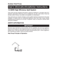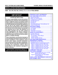
1
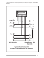
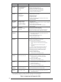
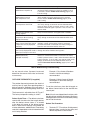
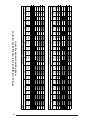
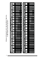
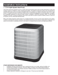
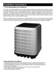
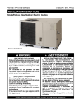
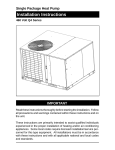
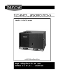
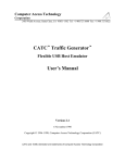
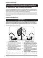
Outdoor Heat Pump
User’s Information/Installation Instructions
14 SEER R-410A High Efficiency Split System
These units have been designed and tested for capacity and efficiency in accordance with A.R.I.
Standards. Split System Heat Pump units are designed for use with a wide variety of fossil fuel
furnaces, electric furnaces, air handlers, and evaporator coil combinations.
These instructions are primarily intended to assist qualified individuals experienced in the proper
installation of heating and/or air conditioning appliances. Some local codes require licensed installation/service personnel for this type of equipment. Read all instructions carefully before starting
the installation.
USER’S INFORMATION
IMPORTANT
Read this owner information to become familiar with the capabilities and use of your appliance.
Keep this with literature on other appliances where you have easy access to it in the future. If a
problem occurs, check the instructions and follow recommendations given. If these suggestions
don’t eliminate your problem, call your servicing contractor.
Heat Pump Principle of Operation
5
4
2
5
1
2
3
6
1
3
4
6
WINTER HEATING
SUMMER COOLING
1. Outdoor air enters heat pump.
2. Cold, heat-transfer section (outdoor coil)
extracts heat from outdoor air as refrigerant
evaporates from a liquid to a gas.
3. Refrigerant, compressed to a hot gas by
heat pump, carries the heat to the hot heattransfer section (indoor coil).
4. Hot, heat-transfer section (indoor coil)
releases the heat to indoor air as refrigerant
condenses from a gas to a liquid.
5. Air handler circulates the heat throughout
the home.
6. Refrigerant returns to outdoor coil and
evaporates once again to absorb more
heat.
1. Indoor air enters the air handler section.
2. Cold, heat-transfer section (indoor coil)
extracts heat from indoor air as refrigerant
evaporates from a liquid to a cold gas.
3. Refrigerant, drawn to heat pump and
compressed to a hot gas by heat pump,
carries the heat outdoors.
4. Hot, heat-transfer section (outdoor coil)
releases the heat as refrigerant condenses
from a gas to a liquid.
5. Heat pump (outdoor fan) discharges the
heat to outside air.
6. Refrigerant returns to indoor coil and
evaporates once again to absorb more
heat.
2
OPERATING INSTRUCTIONS
1. Set the thermostat system switch to COOL
and the thermostat fan switch to AUTO.
(See Figure 1)
2. Set the thermostat temperature to the
desired temperature level using the
temperature selector. Please refer to
the separate detailed thermostat user’s
manual for complete instructions regarding
thermostat programming. The outdoor unit
and indoor blower will both cycle on and
off to maintain the indoor temperature at
the desired heating level.
2. Set the thermostat temperature to the
desired temperature level using the temperature selector. Please refer to the separate detailed thermostat user’s manual for
complete instructions regarding thermostat
programming. The outdoor unit and indoor
blower will both cycle on and off to maintain
the indoor temperature at the desired cooling level.
NOTE: If the thermostat temperature level
is re-adjusted, or the thermostat system
switch is repositioned, the outdoor unit
may not start immediately.The outdoor unit
contains a protective timer circuit which
holds the unit off for approximately five
minutes following a previous operation,
or the interruption of the main electrical
power.
TO OPERATE YOUR HEAT PUMP
FOR COOLING —
NOTE: If the thermostat temperature level
is re-adjusted, or the thermostat system
switch is repositioned, the outdoor unit
may not start immediately. The outdoor unit
contains a protective timer circuit which
holds the unit off for approximately five
minutes following a previous operation,
or the interruption of the main electrical
power.
TO OPERATE YOUR HEAT PUMP
FOR HEATING —
1. Set the thermostat system switch to HEAT
and the thermostat fan switch to AUTO.
(See Figure 1)
Emergency Heat:
The thermostat includes a system switch
position termed EM. HT. This is a back-up
heating mode to be used only if there is
a suspected problem with the outdoor
unit. With the system switch set to EM.
HT. the outdoor unit will be locked off,
and supplemental heat (typically electric
resistance heating) will be used as a source
of heat. Sustained use of electric resistance
heat in place of the heat pump will result
in an increase in electric utility costs.
Defrost:
During cold weather heating operation,
the outdoor unit will develop a coating
Figure 1. Typical Thermostat
3
of snow and ice on the heat transfer coil.
This is normal, and the unit will periodically
defrost itself. During the defrost cycle, the
outdoor fan will stop, and the compressor
will continue to run and heat the outdoor coil,
causing the snow and ice to melt. After the
snow and ice have melted, some steam may
rise from the outdoor unit as the warm coil
causes some melted frost to evaporate.
TO OPERATE YOUR HEAT PUMP
FOR AUTOMATIC COOLING AND
HEATING —
1. Set the thermostat system switch to AUTO
and the thermostat fan switch to AUTO. (See
Figure 1)
Note: Thermostats will vary. Some models
will not include the AUTO mode, and others
will have the AUTO in place of the HEAT and
COOL, and some will include all three.
2. Set the thermostat temperature to the
desired heating and cooling temperature
level(s). The outdoor unit and the indoor
blower will then cycle on and off in either
the heating or cooling mode of operation
as required to automatically maintain the
indoor temperature within the desired
limits.
TO SHUT OFF YOUR HEAT PUMP —
Set the thermostat system switch to OFF and
the thermostat fan switch to AUTO. (See Figure
1) The system will not operate, regardless of the
thermostat temperature selector(s) setting.
TO OPERATE THE INDOOR
BLOWER CONTINUOUSLY —
Set the thermostat fan switch to ON (See Figure
1). The indoor blower will start immediately, and
will run continually until the fan switch is reset
to AUTO.
The continuous indoor blower operation can be
obtained with the thermostat system switch set
in any position, including OFF.
The continuous indoor blower operation is
typically used to circulate the indoor air to
4
equalize a temperature unbalance due to a sun
load, cooking, or fireplace operation.
TO MAINTAIN YOUR HEAT PUMP —
CAUTION:
Be certain the electrical power to
the outdoor unit and the furnace/air
handler is disconnected before
doing the following recommended
maintenance.
1.
Regularly:
a. Clean or replace the indoor air filter at the
start of each heating and cooling season,
and when an accumulation of dust and dirt
is visible on the air filter. Inspect the filter
monthly.
b. Remove any leaves and grass clippings from
the coil in the outdoor unit, being careful
not to damage the aluminum fins.
c. Check for any obstruction such as twigs,
sticks, etc.
CAUTION:
Do not over-oil, or oil motors not
factory-equipped with oil tubes. The
compressor is hermetically “sealed”
and does not require lubrication.
2. Before Calling a Service Technician, Be
Certain:
a. The unit thermostat is properly set — see
“To Operate Your Heat Pump for Cooling”
and “To Operate Your Heat Pump for
Heating.”
b. The unit disconnect fuses are in good
condition, and the electrical power to the
unit is turned on.
Read Your Warranty
Please read the separate warranty document
completely. It contains valuable information
about your system.
GENERAL INFORMATION
SAFETY CONSIDERATIONS
Read the following instructions completely before
performing the installation.
Pressures within the System — Split
system heat pump equipment contains liquid
and gaseous refrigerant under pressure.
Installation and servicing of this equipment
should be accomplished by qualified, trained
personnel thoroughly familiar with this type of
equipment. Under no circumstances should the
Homeowner attempt to install and/or service
the equipment.
CAUTION:
This unit uses refrigerant R-410A. DO
NOT under any circumstances use
any other refrigerant besides R-410A
in this unit. Use of another refrigerant
will damage this unit.
Outdoor Unit Section — Each outdoor unit
is shipped with a refrigerant charge adequate
to operate the outdoor section with an indoor
matching coil or air handler. Units with braze
connections include the proper amount of
refrigerant for an additional 15 ft. of refrigerant
lines the same size as the valve fittings.
NOTE: DO NOT USE ANY PORTION OF
THE CHARGE FOR PURGING OR LEAK
TESTING.
Matching coils and air handlers may be shipped
with a small holding charge to pressurize them to
keep out contaminants. To release the pressure,
read the indoor section installation instructions
carefully.
Liquid and Suction Lines — Fully annealed,
refrigerant grade copper tubing should be used
when installing the system. Refrigerant suction
line tubing should be fully insulated.
Field Connections for Electrical Power
Supply — All wiring must comply with current
provisions of the “National Electrical Code”
(ANSI/NFPA 70) and with applicable local
codes having jurisdiction. The minimum size of
electrical conductors and circuit protection must
be in compliance with information listed on the
outdoor unit data label.
NOTICE:
Certain models have external panels fabricated
from a premium grade of stainless steel designed
to inhibit corrosion. For such units, if the unit is
located in a coastal region or other area subjected
to high concentrations of salt, then the unit should
be hosed off after storms and monthly otherwise
to maintain its new appearance.
Labels, Tags, Precautions — When working
with this equipment, follow all precautions in the
literature, on tags, and on labels provided with
the equipment. Read and thoroughly understand
the instructions provided with the equipment prior
to performing the installation and operational
checkout of the equipment.
Brazing Operations — Installation of equipment
may require brazing operations. Safety codes
must be complied with. Safety equipment (e.g.;
safety glasses, work gloves, fire extinguisher,
etc.) must be used when performing brazing
operations.
WARNING:
Ensure all electrical power to the unit
is off prior to installing or servicing
the equipment. Failure to do so may
cause personal injury or death.
SITE PREPARATION
Unpacking Equipment — Remove the
cardboard carton and User’s Manual from the
equipment. Take care to not damage tubing
connections when removing from the carton.
Inspect for Damage — Inspect the equipment
for damage prior to installing the equipment at
the job site. Ensure coil fins are straight and, if
necessary, comb fins to remove flattened and
bent fins.
Preferred Location of the Outdoor Unit at the
Job Site — Conduct a survey of the job site to
determine the optimum location for mounting
the outdoor unit. Overhead obstructions,
poorly ventilated areas, and areas subject to
accumulation of debris should be avoided. The
5
outdoor unit must be installed in such a manner
that airflow through the coil is not obstructed and
that the unit can be serviced.
Facility Prerequisites — Electrical power
supplied must be adequate for proper operation
of the equipment. The system must be wired and
provided with circuit protection in accordance
with local building codes and the National
Electrical Code.
INSTALLING THE OUTDOOR UNIT
Slab Mount — The site selected for a slab mount
installation requires a stable foundation and one
not subject to erosion. The slab should be level
and anchored (if necessary) prior to placing the
equipment on the slab.
Cantilever Mount — The cantilever mount
should be designed with adequate safety factor
to support the weight of the equipment, and for
loads subjected to the mount during operation.
Installed equipment should be adequately
secured to the cantilever mount and levelled
prior to operation of the equipment.
Roof Mount — The method of mounting should
be designed so as not to overload roof structures
nor transmit noise to the interior of the structure.
Refrigerant and electrical line should be routed
through suitably waterproofed openings to
prevent water leaking into the structure.
INSTALLING THE INDOOR UNIT
The indoor section should be installed before
proceeding with routing of refrigerant piping.
Consult the Installation Instructions of the indoor
unit (i.e.: air handler, furnace, etc.) for details
regarding installation.
CONNECTING REFRIGERANT
TUBING BETWEEN THE INDOOR
AND OUTDOOR UNIT
CAUTION:
This system utilizes R-410A refrigerant
with POE oil. When servicing, cover
or seal openings to minimize the
exposure of the refrigerant system
to air to prevent accumulation of
moisture and other contaminants.
6
General — Once outdoor and indoor unit
placement has been determined, route refrigerant
tubing between the equipment in accordance with
sound installation practices. Refrigerant tubing
should be routed in a manner that minimizes the
length of tubing and the number of bends in the
tubing. Refrigerant tubing should be supported
in a manner that the tubing will not vibrate or
abrade during system operation. Tubing should
be kept clean of foreign debris during installation
and installation of a liquid line filter drier is
recommended if cleanliness or adequacy of
system evacuation is unknown or compromised.
Every effort should be made by the installer
to ensure that the field installed, refrigerant
containing components of the system have been
installed in accordance with these instructions
and sound installation practices so as to insure
reliable system operation and longevity.
The maximum recommended interconnecting
refrigerant line length is 75 feet, and the
vertical elevation difference between the indoor
and outdoor sections should not exceed 20
feet. Consult long line application guide for
installations in excess of these limits.
Filter Dryer Installation — A filter dryer is
provided with the unit and must be installed in the
liquid line of the system. If the installation replaces
a system with a filter dryer already present in the
liquid line, the filter dryer must be replaced with
the one supplied with the unit. The filter dryer
must be installed in strict accordance with the
manufacturer’s installation instructions.
Optional Equipment — Optional equipment
(e.g.: liquid line solenoid valves, etc.) should
be installed in strict accordance with the
manufacturer’s installation instructions.
ELECTRICAL CONNECTIONS
WARNING:
Turn off all electrical power at the main
circuit box before wiring electrical
power to the outdoor unit. Failure to
comply may cause severe personnel
injury or death.
Wiring Diagram/Schematic — A wiring
diagram/schematic is located on the inside cover
of the electrical box of the outdoor unit. The
installer should become familiar with the wiring
diagram/schematic before making any electrical
connections to the outdoor unit.
Outdoor Unit Connections — The outdoor
unit requires both power and control circuit
electrical connections. Refer to the unit wiring
diagram/schematic for identification and location
of outdoor unit field wiring interfaces.
Control Circuit Wiring — The outdoor unit is
designed to operate from a 24 VAC Class II control
circuit. Control circuit wiring must comply with
the current provisions of the “National Electrical
Code” (ANSI/NFPA 70) and with applicable local
codes having jurisdiction.
Thermostat connections should be made in
accordance with the instructions supplied with
the thermostat, and with the instructions supplied
with the indoor equipment. A typical residential
installation with a heat pump thermostat and air
handler are shown below.
Electrical Power Wiring — Electrical power
wiring must comply with the current provisions
of the “National Electrical Code” (ANSI/NFPA
70) and with applicable local codes having
jurisdiction. Use of rain tight conduit is
recommended. Electrical conductors shall have
minimum circuit ampacity in compliance with the
outdoor unit rating label. The facility shall employ
electrical circuit protection at a current rating no
greater than that indicated on the outdoor unit
rating label. Refer to the unit wiring diagram for
connection details.
Minimum Circuit Ampacity — Electrical wiring
to the equipment must be compatible and in
compliance with the minimum circuit ampacity
listed on the outdoor unit data label.
COPPER WIRE SIZE — AWG
(1% Voltage Drop)
Supply Wire Length-Feet
Supply Circuit
200
150
100
50
Ampacity
6
4
4
4
3
3
2
2
8
6
6
4
4
4
3
3
10
8
8
6
6
6
4
4
14
12
10
10
8
8
6
6
15
20
25
30
35
40
45
50
Maximum Fuse/Circuit Breaker Size — Circuit
protection for the outdoor unit must be compatible
with the maximum fuse/circuit breaker size listed
on the outdoor unit data label.
Disconnect Switch — An electrically compatible
disconnect switch must be within line of sight of
the outdoor unit. This switch shall be capable of
electrically de-energizing the outdoor unit.
Optional Equipment — Optional equipment
requiring connection to the power or control
circuits must be wired in strict accordance with
current provisions of the “National Electrical
Code” (ANSI/NFPA 70), with applicable local
codes having jurisdiction, and the installation
instructions provided with the equipment.
Optional Equipment (e.g.: liquid line solenoid
valves, hard start kits, low suction pressure
cutout switch kit, high pressure cutout switch kit,
refrigerant compressor crankcase heater, etc.)
should be installed in strict accordance with the
manufacturer’s installation instructions.
STARTUP AND CHECKOUT
WARNING:
Ensure electrical power to the unit is
off prior to performing the following
steps. Failure to do so may cause
personal injury or death.
Air Filters — Ensure air filters are clean and in
place prior to operating the equipment.
Thermostat — Set the room thermostat function
switch to OFF, fan switch to AUTO, and adjust the
temperature setpoint to its highest setting.
Prior to applying electrical power to the outdoor
unit, ensure that the unit has been properly and
securely grounded, and that power supply
connections have been made at both the facility
power interface and outdoor unit.
Outdoor Unit — Ensure the outdoor coil and
top of the unit are free from obstructions and
debris, and all equipment access/control panels
are in place.
Using extreme caution, apply power to the unit
and inspect the wiring for evidence of open,
shorted, and/or improperly wired circuits.
Wire Size based on N.E.C. for 60° type copper conductors.
7
Thermostat
G R W 2C E O Y
Green
G
Red
R
Brown
W
NOTE: Jumper
between W2 and E is
required when no OD
T-Stat is used.
R
W2
Orange W 2
For 2-Stage
Heater
Kits
Grey
C O Y
C
Air Handler
Heat Pump OD
Section
Typical Heat Pump with Standard Air Handler
8
A typical installation with a heat pump thermostat, air handler, and heat pump with an outdoor
thermostat.
Thermostat
G R W 2C E O Y
Green
G
Red
R
E
R
White
W
W2
C O Y
Grey
C
Air Handler
Heat Pump OD
Section
Typical Heat Pump with
Outdoor Thermostat and Air Handler
9
Functional Checkout:
CAUTION:
If equipped with a compressor
crankcase heater, wait 24 hours prior
to performing a function checkout to
allow for heating of the compressor
crankcase. Failure to comply may
result in damage and could cause
premature failure of the system.
Indoor Blower — Set the thermostat function
switch to COOLING and the fan switch to ON.
Verify that the indoor blower is operating and
that airflow is not restricted. Set the fan switch
back to AUTO.
Blower Time Delay Relay (Select Models): A
time delay relay may be provided with the unit and
must be installed in the indoor section. The relay
will keep the indoor blower running an additional
40 seconds for increased cooling efficiency after
the outdoor unit shuts off. The relay has four
terminals and one mounting hole.
Connect terminal “1” to load side of blower relay.
Connect terminal: “2” to terminal “R” of T’stat.
Connect terminal “3” to common terminal at
blower relay or transformer. Connect terminal
“4” to terminal “G” on T’stat.
Low-Pressure Switch (Select Models) — A
low-pressure switch is factory-installed in select
models only. If provided, this switch is located in
the suction line internal to the outdoor unit. The
switch is designed to protect the compressor
from a loss of charge. Under normal conditions,
the switch is closed. If the suction pressure falls
below 5 psig, then the switch will open and deenergize the outdoor unit. The switch will close
again once the suction pressure increases above
20 psig. Please note that the switch interrupts
the thermostat inputs to the unit. Thus, when the
switch opens and then closes, there will be a 5
minute short cycling delay before the outdoor
unit will energize.
High-Pressure Switch — A high-pressure
switch is factory-installed and located in the
compressor discharge line internal to the outdoor
unit. The switch is designed to de-energize the
system when very high pressures occur during
abnormal conditions. Under normal conditions,
10
the switch is closed. If the discharge pressure
rises above 575 psig, then the switch will open
and de-energize the outdoor unit. The switch
will close again once the discharge pressure
decreases to 460 psig. Please note that the switch
interrupts the thermostat inputs to the unit. Thus,
when the switch opens and then closes, there
will be a 5 minute short cycling delay before the
outdoor unit will energize.
Short Cycle Protection — With the system
operating in COOLING mode, note the setpoint
temperature setting of the thermostat, and
gradually raise the setpoint temperature until
the outdoor unit and indoor blower de-energize.
Immediately lower the setpoint temperature of
the thermostat to its original setting and verify
that the indoor blower is energized and that the
outdoor unit remains de-energized. Verify that,
after approximately 5 minutes, the outdoor unit
energizes and that the temperature of the air
supplied to the facility is cooler than ambient
temperature.
Comfort AlertTM Diagnostics (Select Models)
— The Comfort AlertTM diagnostics module
facilitates troubleshooting heat pump and air
conditioning system failures. This Comfort
AlertTM module is designed only for single-phase
systems with scroll compressors that have
internal overload protection. By monitoring and
analyzing data from the compressor and the
thermostat demand, the module can detect the
cause of electrical and system related failures
without any sensors. A flashing LED indicator
communicates the ALERT code and guides the
service technician more quickly and accurately
to the root cause of a problem.
NOTE: This module does not provide safety
protection! The Comfort AlertTM module is a
monitoring device and cannot control or shut
down other devices.
LED Description (See Figure 2)
POWER LED (Green): indicates voltage is present
at the power connection of the module.
ALERT LED (Yellow): communicates an
abnormal system condition through a unique
flash code. The ALERT LED will flash a number
of times consecutively, pause and then repeat
the process. The number of consecutive
flashes, defined as the Flash Code, correlates
to a particular abnormal condition. Detailed
descriptions of specific ALERT Flash Codes are
shown in Table 1 of this manual.
TRIP LED (Red): indicates there is a demand
signal from the thermostat but no current to the
compressor is detected by the module. The TRIP
LED typically indicates the compressor protector
is open or may indicate missing supply power
to the compressor.
The scroll compressor’s run (R), common (C)
and start (S) wires are routed through the holes
in the Comfort AlertTM module marked “R,” “C”
and “S.”
TM
24 VAC Power Wiring — The Comfort Alert
module requires a constant nominal 24 VAC
power supply. The wiring to the module’s R and
C terminals must be directly from the indoor unit
or thermostat.
The Comfort AlertTM module requires a thermostat
demand signal to operate properly.
NOTE: After the thermostat demand signal is
connected, verify that 24 VAC across Y and C
when demand is present.
TROUBLESHOOTING
Interpreting The Diagnostic LEDs – When
an abnormal system condition occurs, the
Comfort AlertTM module displays the appropriate
ALERT and/or TRIP LED will flash a number of
times consecutively, pause and then repeat the
process. To identify a Flash Code number, count
the number of consecutive flashes.
Every time the module powers up, the last
ALERT Flash Code that occurred prior to shut
down is displayed for one minute. The module
will continue to display the LED until the condition
returns to normal or if 24 VAC power is removed
from the module.
Cooling — Gradually lower the thermostat
temperature setpoint below the actual room
temperature and observe that the outdoor unit
and indoor blower energize. Feel the air being
circulated by the indoor blower and verify that
it is cooler than ambient temperature. Listen
for any unusual noises. If present, locate and
determine the source of the noise and correct
as necessary.
Heating — Lower the thermostat setpoint
temperature to the lowest obtainable setting and
set the thermostat function switch to HEATING.
The indoor blower and outdoor unit should stop
running. After a minimum of five minutes, increase
the setpoint temperature of the thermostat to the
maximum setting.Verify that the outdoor unit and
indoor blower have energized. Feel the air being
circulated by the indoor blower and verify that
it is warmer than ambient temperature. Listen
POWER
ALERT
TRIP
Figure 2. Comfort AlertTM Diagnostics
Module
11
Status LED
Status LED Description
Status LED Troubleshooting Information
Green “POWER”
Module has power
Supply voltage is present at module terminals
Red “TRIP”
Thermostat demand signal
Y is present, but the
compressor is not
running
1.
2.
3.
4.
5.
6.
Compressor protector is open
Outdoor unit power disconnect is open
Compressor circuit breaker or fuse(s) is open
Broken wire or connector is not making contact
Low pressure switch open if present in system
Compressor contactor has failed open
Yellow “ALERT”
Flash Code 1
Long Run Time
Compressor is
running extremely
long run cycles
1.
2.
3.
4.
5.
6.
7.
8.
Low refrigerant charge
Evaporator blower is not running
Evaporator coil is frozen
Faulty metering device
Condenser coil is dirty
Liquid line restriction (filter drier blocked if present in system)
Thermostat is malfunctioning
Comfort Alert Failure
Yellow “ALERT”
Flash Code 2
System Pressure Trip
Discharge or suction
pressure out of limits or
compressor overloaded
1.
2.
3.
4.
5.
High head pressure
Condenser coil poor air circulation (dirty, blocked, damaged)
Condenser fan is not running
Return air duct has substantial leakage
If low pressure switch present in system, check Flash
Code 1 information
Yellow “ALERT”
Flash Code 3
Short Cycling
Compressor is running
only briefly
1. Thermostat demand signal is intermittent
2. Time delay relay or control board defective
3. If high pressure switch present go to Flash Code 2 information
4. If low pressure switch present go to Flash Code 1 information
Yellow “ALERT”
Flash Code 4
Locked Rotor
Yellow “ALERT”
Flash Code 5
Open Circuit
1. Run capacitor has failed
2. Low line voltage (contact utility if voltage at disconnect is low)
• Check wiring connections
3. Excessive liquid refrigerant in compressor
4. Compressor bearings are seized
• Measure compressor oil level
1. Outdoor unit power disconnect is open
2. Compressor circuit breaker or fuse(s) is open
3. Compressor contactor has failed open
• Check compressor contactor wiring and connectors
• Check for compressor contactor failure (burned, pitted or
open)
• Check wiring and connectors between supply and
compressor
• Check for low pilot voltage at compressor contactor coil
4. High pressure switch is open and requires manual reset
5. Open circuit in compressor supply wiring or connections
6. Unusually long compressor protector reset time due to
extreme ambient temperature
7. Compressor windings are damaged
• Check compressor motor winding resistance
Yellow “ALERT”
Flash Code 6
Open Start Circuit
Current only in run circuit
1. Run capacitor has failed
2. Open circuit in compressor start wiring or connections
• Check wiring and connectors between supply and the
compressor “S” terminal
3. Compressor start winding is damaged
• Check compressor motor winding resistance
Yellow “ALERT”
Flash Code 7
Open Run Circuit
Current only in start circuit
1. Open circuit in compressor run wiring or connections
• Check wiring and connectors between supply and the
compressor “R” terminal
2. Compressor run winding is damaged
• Check compressor motor winding resistance
Yellow “ALERT”
Flash Code 8
Welded Contactor
Compressor always runs
1. Compressor contactor has failed closed
2. Thermostat demand signal not connected to module
Yellow “ALERT”
Flash Code 9
Low Voltage
Control circuit < 17VAC
1. Control circuit transformer is overloaded
2. Low line voltage (contact utility if voltage at disconnect is low)
• Check wiring connections
• Flash Code number corresponds to a number of LED flashes, followed by a pause and then repeated.
• TRIP and ALERT LEDs flashing at same time means control circuit voltage is too low for operation.
Table 1. Interpreting the Diagnostic LEDS
12
Miswired Module Indication
Recommended Troubleshooting Action
Green LED is not on,
module does not power up
Determine if both R and C module terminals are
connected. Verify voltage is present at module’s R and
C terminals. Review 24VAC Power W iring (page 4) for
R and C wiring.
Green LED intermittent,
module powers up only
when compressor runs
Determine if R and Y terminals are wired in reverse.
Verify module’s R and C terminals have a constant
source. Review 24VAC Power W iring (page 4) for R
and C wiring.
TRIP LED is on but system
and compressor check OK
Verify Y terminal is connected to 24VAC at contactor
coil. Verify voltage at contactor coil falls below 0.5VAC
when off. Verify 24 VAC is present across Y and C when
thermostat demand signal is present. If not, R and C are
reverse wired.
TRIP LED and ALERT LED
flashing together
Verify R and C terminals are supplied with 19-28VAC.
ALERT Flash Code 3
(Compressor Short Cycling)
displayed incorrectly
Verify Y terminal is connected to 24VAC at contactor coil.
Verify voltage at contactor coil falls below 0.5VAC when
off.
ALERT Flash Code 5, 6 or 7
(Open Circuit, Open Start Circuit
or Open Run Circuit) displayed
incorrectly
Check that compressor run and start wires are through
module’s current sensing holes. Verify Y terminal is
connected to 24VAC at contactor coil. Verify voltage at
contactor coil falls below 0.5VAC when off.
ALERT Flash Code 6 (Open
Check that compressor run and start wires are routed
Start Circuit) displayed for Code 7 through the correct module sensing holes.
(Open Run Circuit) or vice versa
ALERT Flash Code 8
(Welded Contactor)
displayed incorrectly
Determine if module’s Y terminal is connected. Verify Y
terminal is connected to 24VAC at contactor coil. Verify
24VAC is present across Y and C when thermostat demand
signal is present. If not, R and C are reverse wired. V erify
voltage at contactor coil falls below 0.5VAC when off.
Review Thermostat Demand Wiring (page 4) for Y and C
wiring.
Table 2. Module Wiring Troubleshooting
for any unusual noises. If present, locate and
determine the source of the noise and correct
as necessary.
Example 1. Dry climate of Southern
Arizona. A 90 minute setting is
recommended.
OUTDOOR THERMOSTAT (if supplied)
Example 2. Moist climate of Seattle,
Washington. A 30 minute setting is
recommended.
The outdoor thermostat prevents the electrical
auxiliary heat (if used) from operating above a
desired set point. Selection of the set point is
determined from the building design heat load.
The thermostat is adjustable from 45°F to 0°F.
The factory temperature setting is at 40°F.
Defrost Cycle Timer — The defrost cycle timer
controls the time interval of the hot gas defrost
after the defrost sensor closes. It is located
in the lower left corner of the defrost control
board. Three interval settings are available: 30
minutes, 60 minutes, and 90 minutes.Time setting
selection is dependent on the climate where the
unit is being installed.
To set the cycle timer, place the timing pin on
the defrost control board to the desired time
interval post.
Note: All units are shipped from the factory with
the default time setting of 30 minutes. Maximum
heating performance can be achieved by setting
the time to 90 minutes.
Defrost Test Procedure
1.
Terminals “R”-”C” must have 18-30v present
between them in order for time delay and
defrost sequences to be initiated.
13
2.
3.
4.
With compressor running in heat mode,
first jump the “T2”-”DFT” test pins. This
will indicate to board that defrost T-stat is
closed. Defrost T-stat closes at 32°, opens
at 68°.
Next jump the “Test” pin to “C” on terminal
strip. This will initiate defrost test in 5, 10 or
15 seconds (This is determined by 30, 60
or 90 minutes defrost pin settings). Factory
setting will be 30 minutes.
Note: If jumper is left on the “Test” to “common”
pins permanently, the defrost cycle will become
inoperable.
Optional Equipment — A functional checkout
should be performed in accordance with
the checkout procedures supplied with the
equipment.
Adjustment of Refrigerant Charge:
When the reversing valve shifts to the
defrost mode, quickly remove jumper from
“Test”-”C”. If the jumper is not removed
within a 5 second period, the defrost test
will terminate. Unit will continue to stay in
defrost mode Until :
A) Board recognizes that defrost
sensor has reached 68° and
opened or
B) “T2”-”DFT” jumper is removed or
C) 10 minutes have elapsed (board
override)
CAUTION:
Split system heat pump equipment
contains liquid and gaseous refrigerant
under pressure. Adjustment of
refrigerant charge should only be
attempted by qualified, trained
personnel thoroughly familiar with the
equipment. Under no circumstances
should the homeowner attempt to
install and/or service this equipment.
Failure to comply with this warning
could result in equipment damage,
personal injury, or death.
If the above steps will not initiate a defrost, replace
the defrost board.
Anti Short Cycle Timer Test
The 5 minute time delay feature can be bypassed
or shortened to 1 second by jumping the “Test”
to “C” terminal.
NOTE: The following Refrigerant Charging
Charts are applicable to listed assemblies of
equipment and at listed airflows for the indoor
coil. Assemblies of indoor coils and outdoor units
not listed are not recommended.
14 SEER SPLIT SYSTEM HEAT PUMP ORIFICE USAGE
Model
Number *T4BE
018K
024K
030K
036K
042K
048K
060K
Restrictor Bore Size (in.)
Outdoor
System Charge
R-410A (oz.)
.037
.041
.041
.055
.055
.062
.067
166
166
168
174
256
246
230
NOTE: Indoor refrigerant metering device is TXV for all models.
14
Refrigerant Charging Charts for Cooling Mode of Operation
14 SEER Split System Cooling Charts
1.5 T on Heat P ump T XV C ooling C harging C hart
550
525
500
Liquid P res s ure (ps ig)
475
450
Remove refrigerant when above curve
425
400
375
350
325
300
Add refrigerant when below curve
275
250
225
200
70
75
80
85
90
95
100
105
110
115
120
125
130
Liquid T emperature (F )
2 T on Heat P ump T XV C ooling C harging C hart
550
525
500
Liquid P res s ure (ps ig)
475
Remove refrigerant when above curve
450
425
400
375
350
325
Add refrigerant when below curve
300
275
250
225
200
70
75
80
85
90
95
100
105
110
115
120
125
130
Liquid T emperature (F )
15
Refrigerant Charging Charts for Cooling Mode of Operation
14 SEER Split System Cooling Charts
2.5 T on Heat P ump T XV C ooling C harging C hart
550
525
500
Liquid P res s ure (ps ig)
475
450
Remove refrigerant when above curve
425
400
375
350
325
300
Add refrigerant when below curve
275
250
225
200
70
75
80
85
90
95
100
105
110
115
120
125
130
125
130
Liquid T emperature (F )
3 T on Heat P ump T XV C ooling C harging C hart
550
525
500
Liquid P res s ure (ps ig)
475
Remove refrigerant when above curve
450
425
400
375
350
325
Add refrigerant when below curve
300
275
250
225
200
70
75
80
85
90
95
100
105
Liquid T emperature (F )
16
110
115
120
Refrigerant Charging Charts for Cooling Mode of Operation
14 SEER Split System Cooling Charts
3.5 T on Heat P ump T XV C ooling C harging C hart
550
525
500
Liquid P res s ure (ps ig)
475
Remove refrigerant when above curve
450
425
400
375
350
325
Add refrigerant when below curve
300
275
250
225
200
70
75
80
85
90
95
100
105
110
115
120
125
130
125
130
Liquid T emperature (F )
4 T on Heat P ump T XV C ooling C harging C hart
550
525
500
Liquid P res s ure (ps ig)
475
Remove refrigerant when above curve
450
425
400
375
350
325
Add refrigerant when below curve
300
275
250
225
200
70
75
80
85
90
95
100
105
110
115
120
Liquid T emperature (F )
17
Refrigerant Charging Charts for Cooling Mode of Operation
14 SEER Split System Cooling Charts
5 T on Heat P ump T XV C ooling C harging C hart
550
525
500
Liquid P res s ure (ps ig)
475
450
Remove refrigerant when above curve
425
400
375
350
325
300
Add refrigerant when below curve
275
250
225
200
70
75
80
85
90
95
100
105
Liquid T emperature (F )
18
110
115
120
125
130
19
OUTDOOR TEMPERATURE (DEG. F)
Suc.
0
10
20
30
40
50
60
Liquid Disch. Suc. Liquid Disch. Suc. Liquid Disch. Suc. Liquid Disch. Suc. Liquid Disch. Suc. Liquid Disch. Suc. Liquid Disch.
Press Press. Temp. Press. Press. Temp. Press. Press. Temp. Press. Press. Temp. Press. Press. Temp. Press. Press. Temp. Press. Press. Temp.
39
199
106
55
229
116
70
259
126
85
290
135
101
309
151
118
341
172
135
373
193
40
206
104
56
235
114
71
264
124
86
293
133
102
316
148
119
348
167
136
380
187
41
213
102
57
241
112
72
269
122
87
297
131
103
323
145
120
355
163
137
387
181
42
220
100
58
247
110
73
274
120
88
301
129
104
330
142
121
362
158
138
394
175
43
227
98
59
253
108
74
278
118
89
304
127
105
337
139
122
369
154
139
401
168
44
234
96
60
258
106
75
283
116
90
308
125
106
344
136
123
376
149
140
408
162
45
241
94
61
264
104
76
288
114
91
312
123
107
351
134
124
383
145
141
415
156
018K
*Note: All pressures are listed in psig. and all temperatures in deg. F.
- Shaded boxes indicate flooded conditions
- Rated design values. Suction Pressure will be lower than design value if indoor air flow, entering dry bulb, or
entering wet bulb temperatures are lower than design.
- Discharge temperatures greater than charted values indicates a refrigerant undercharge.
REFRIGERANT CHARGING CHARTS LEGEND FOR HEATING MODES OF OPERATION
Refrigerant Charging Charts for Heating Mode of Operation
14 SEER Split System Heating Charts
20
Liquid
0
Disch. Suc. Liquid
10
Disch. Suc. Liquid
20
Disch. Suc. Liquid
30
Disch. Suc. Liquid
40
50
Disch. Suc. Liquid
OUTDOOR TEMPERATURE (DEG. F)
Disch. Suc. Liquid
60
Disch.
209
216
223
230
237
244
251
117
115
113
111
109
107
105
53
54
55
56
57
58
59
242
248
254
260
266
272
278
124
122
120
118
116
114
112
68
69
70
71
72
73
74
276
280
285
290
295
299
304
132
130
128
126
124
122
120
309
312
316
320
323
327
331
139
137
135
133
131
129
127
98
99
100
101
102
103
104
333
340
347
354
361
368
375
155
153
150
147
144
141
138
OUTDOOR TEMPERATURE (DEG. F)
82
83
84
85
86
87
88
117
118
119
120
121
122
123
371
378
385
392
399
406
413
180
175
171
166
162
157
153
135
136
137
138
139
140
141
408
415
422
429
436
443
450
204
198
192
186
180
174
167
0
10
20
30
40
50
60
Suc. Liquid Disch. Suc. Liquid Disch. Suc. Liquid Disch. Suc. Liquid Disch. Suc. Liquid Disch. Suc. Liquid Disch. Suc. Liquid Disch.
Press Press. Temp. Press. Press. Temp. Press. Press. Temp. Press. Press. Temp. Press. Press. Temp. Press. Press. Temp. Press. Press. Temp.
36
198
114
51
237
124
65
276
135
80
315
145
95
343
162
110
382
183
126
422
205
37
205
112
52
243
122
66
281
133
81
319
143
96
350
159
111
389
179
127
429
199
38
212
110
53
249
120
67
286
131
82
322
141
97
357
156
112
396
174
128
436
193
39
219
108
54
255
118
68
290
129
83
326
139
98
364
153
113
403
170
129
443
187
40
226
106
55
261
116
69
295
127
84
330
137
99
371
150
114
410
165
130
450
181
41
233
104
56
266
114
70
300
125
85
333
135
100
378
147
115
417
161
131
457
174
42
240
102
57
272
112
71
305
123
86
337
133
101
385
145
116
424
156
132
464
168
030K
39
40
41
42
43
44
45
Press Press. Temp. Press. Press. Temp. Press. Press. Temp. Press. Press. Temp. Press. Press. Temp. Press. Press. Temp. Press. Press. Temp.
Suc.
024K
Refrigerant Charging Charts for Heating Mode of Operation
14 SEER Split System Heating Charts
21
Liquid
0
Disch. Suc. Liquid
10
Disch. Suc. Liquid
20
Disch. Suc. Liquid
30
Disch. Suc. Liquid
40
50
Disch. Suc. Liquid
OUTDOOR TEMPERATURE (DEG. F)
Disch. Suc. Liquid
60
Disch.
199
206
213
220
227
234
241
116
114
112
110
108
106
104
50
51
52
53
54
55
56
227
233
239
245
251
256
262
123
121
119
117
115
113
111
65
66
67
68
69
70
71
255
260
265
269
274
279
284
129
127
125
123
121
119
117
283
287
290
294
298
301
305
136
134
132
130
128
126
124
95
96
97
98
99
100
101
299
306
313
320
327
334
341
150
147
144
141
139
136
133
OUTDOOR TEMPERATURE (DEG. F)
80
81
82
83
84
85
86
111
112
113
114
115
116
117
325
332
339
346
353
360
367
171
166
162
157
153
148
144
127
128
129
130
131
132
133
351
358
365
372
379
386
393
191
185
179
173
167
160
154
Suc.
0
10
20
30
40
50
60
Liquid Disch. Suc. Liquid Disch. Suc. Liquid Disch. Suc. Liquid Disch. Suc. Liquid Disch. Suc. Liquid Disch. Suc. Liquid Disch.
Press Press. Temp. Press. Press. Temp. Press. Press. Temp. Press. Press. Temp. Press. Press. Temp. Press. Press. Temp. Press. Press. Temp.
35
208
111
49
234
124
63
261
137
76
288
150
90
304
163
103
331
174
116
358
186
36
215
109
50
240
122
64
266
135
77
292
148
91
311
160
104
338
170
117
365
180
37
222
107
51
246
120
65
271
133
78
295
146
92
318
157
105
345
165
118
372
174
38
229
105
52
252
118
66
276
131
79
299
144
93
325
154
106
352
161
119
379
168
39
236
103
53
258
116
67
280
129
80
303
142
94
332
151
107
359
156
120
386
162
40
243
101
54
264
114
68
285
127
81
306
140
95
339
148
108
366
152
121
393
155
41
250
99
55
270
112
69
290
125
82
310
138
96
346
146
109
373
147
122
400
149
042K
35
36
37
38
39
40
41
Press Press. Temp. Press. Press. Temp. Press. Press. Temp. Press. Press. Temp. Press. Press. Temp. Press. Press. Temp. Press. Press. Temp.
Suc.
036K
Refrigerant Charging Charts for Heating Mode of Operation
14 SEER Split System Heating Charts
22
OUTDOOR TEMPERATURE (DEG. F)
OUTDOOR TEMPERATURE (DEG. F)
39
40
41
255
262
269
144
142
140
50
51
52
273
279
285
151
149
147
61
62
63
291
296
300
158
156
154
72
73
74
309
312
316
165
163
161
83
84
85
332
339
346
170
168
165
92
93
94
352
359
366
174
169
165
101
102
103
373
380
387
177
171
165
0
10
20
30
40
50
60
Suc. Liquid Disch. Suc. Liquid Disch. Suc. Liquid Disch. Suc. Liquid Disch. Suc. Liquid Disch. Suc. Liquid Disch. Suc. Liquid Disch.
Press Press. Temp. Press. Press. Temp. Press. Press. Temp. Press. Press. Temp. Press. Press. Temp. Press. Press. Temp. Press. Press. Temp.
35
227
152
46
249
159
57
272
166
68
294
173
79
304
182
88
324
192
97
345
202
36
234
150
47
255
157
58
276
164
69
298
171
80
311
179
89
331
187
98
352
195
37
241
148
48
261
155
59
281
162
70
301
169
81
318
176
90
338
183
99
359
189
38
248
146
49
267
153
60
286
160
71
305
167
82
325
173
91
345
178
100
366
183
060K
0
10
20
30
40
50
60
Suc. Liquid Disch. Suc. Liquid Disch. Suc. Liquid Disch. Suc. Liquid Disch. Suc. Liquid Disch. Suc. Liquid Disch. Suc. Liquid Disch.
Press Press. Temp. Press. Press. Temp. Press. Press. Temp. Press. Press. Temp. Press. Press. Temp. Press. Press. Temp. Press. Press. Temp.
37
217
126
50
237
133
62
256
141
75
276
148
88
283
158
101
302
170
114
322
183
38
224
124
51
243
131
63
261
139
76
279
146
89
290
155
102
309
166
115
329
177
39
231
122
52
248
129
64
266
137
77
283
144
90
297
152
103
316
161
116
336
170
40
238
120
53
254
127
65
270
135
78
287
142
91
304
149
104
323
157
117
343
164
41
245
118
54
260
125
66
275
133
79
290
140
92
311
146
105
330
152
118
350
158
42
252
116
55
266
123
67
280
131
80
294
138
93
318
143
106
337
148
119
357
152
43
259
114
56
272
121
68
285
129
81
298
136
94
325
141
107
344
143
120
364
146
048K
Refrigerant Charging Charts for Heating Mode of Operation
14 SEER Split System Heating Charts
23
INSTALLER: PLEASE LEAVE
THESE INSTALLATION
INSTRUCTIONS WITH THE
HOMEOWNER.
¢708695W¤
7086950
7086950
Specifications and illustrations subject to change
without notice and without incurring obligations.
Printed in U.S.A. (02/07)