1
HELSINKI UNIVERSITY OF TECHNOLOGY
Department of Communications and Networking
Communications Laboratory
Jyri Ilama
Functional regression testing and test automation in a 3G
network element platform environment
Master’s Thesis
Espoo, January 18, 2010
Supervisor:
Professor Jyri Hämäläinen, D.Sc
Instructor:
Jari Simolin, M.Sc
HELSINKI UNIVERSITY OF TECHNOLOGY
Department of Communications and Networking
Author
ABSTRACT OF MASTER’S
THESIS
Date
Jyri Ilama
January 18, 2010
Pages
79 + 4
Title of thesis
Functional regression testing and test automation in a 3G network element
platform environment
Professorship
Communications
Professorship Code
S-72
Supervisor
Professor Jyri Hämäläinen, D.Sc.
Instructor
Jari Simolin, M.Sc
This study is about lessons learned in automating the functional regression testing of a
complex 3G network element platform that has very strict requirements of fault-tolerance.
This test automation process contains automating functional testing test cases as well as
automating the whole regression testing, ending in using a continuous integration server.
Lots of things went wrong and should have been done otherwise during this project that
contained the implementation of a new functional testing tool, taking it into use as a part of
our continuous integration strategy and making the regression testing fully automatic;
giving reasonable, clear and illustrative results that would lead to a better quality of the
whole software. Lots of lessons were learned and all of these are documented here; pitfalls
to avoid and good practices to obey, as well as focusing on the essential things in this kind
of a project – as well as in the implementation of any software as big as this is.
Keywords
Functional testing, regression testing, test automation, continuous integration, 3G, IPA2800
TEKNILLINEN KORKEAKOULU
DIPLOMITYÖN TIIVISTELMÄ
Tietoliikenne- ja tietoverkkotekniikan laitos
Tekijä
Päiväys
Jyri Ilama
18. Tammikuuta 2010
Sivumäärä
79 + 4
Työn nimi
Toiminnallisuuden regressiotestaaminen ja testiautomaatio 3Gverkkoelementtialustaympäristössä
Professuuri
Koodi
Tietoliikennetekniikka
S-72
Valvoja
Professori Jyri Hämäläinen, TkT
Ohjaaja
Jari Simolin, FK
Tämä tutkimus kertoo asioista, joita opittiin monimutkaisen 3G-verkkoelementtialustan,
jolla on hyvin tiukat vikasietovaatimukset, toiminnallisuuden regressiotestaamisen
automatisoinnissa. Tämä testiautomaatioprosessi sisältää sekä toimintotestauksen testitapausten että koko niiden regressiotestaamisen automatisoinnin, päätyen jatkuvan
integraation palvelimen käyttöön. Moni asia tehtiin väärin tämän projektin aikana, ja nämä
asiat olisi ehdottomasti pitänyt tehdä toisin. Projekti sisälsi uuden toimintotestaustyökalun
toteuttamisen ja sen käyttöönoton osana jatkuvan integraation suunnitelmaamme, sekä
regressiotestauksen täyden automatisoinnin, antaen selkeitä ja havainnollisia tuloksia, jotka
lopulta johtavat koko alustan parempaan laatuun. Paljon asioita opittiin ja ne on esitetty
tässä työssä: sekä sudenkuoppia, joita tulee välttää että hyviä käytäntöjä, joita tulisi
noudattaa, kuin myös oleellisiin asioihin keskittymistä tällaisessa projektissa – niin kuin
mitä tahansa näin laajaa ohjelmistoa tuotettaessa.
Avainsanat
Toimintotestaus, regressiotestaus, testiautomaatio, jatkuva integraatio, 3G, IPA2800
i
Preface
This Master’s Thesis is a research about a test automation and continuous integration
project at the Call Management domain of Nokia Siemens Networks. The idea for
this project came because of the unsuccessful attempts to execute the functional
regression testing part of our continuous integration strategy with a quality,
traceability and maintainability good enough, beginning with the implementation of a
new software tool for functional testing.
I was involved in this project already from the software implementation phase,
ascending to the role of a test coordinator of our requirement area, because of all the
knowledge and required information gained about our testing during this project.
In the beginning of fall 2009, there was great uncertainty whether I would get this
thesis worker job at all. I would like to give my biggest compliments to Marko
Klemetti, my current team leader at Eficode Oy, who made this all possible. In
practice, even though I moved into another company’s pay lists, I got the chance to
continue working on the same project in which I was involved earlier when still
working for Nokia Siemens Networks.
I would also like to thank Jari Simolin, my instructor and former manager at NSN,
who gave me quite free hands with this thesis work, trusting on my own competence
on this topic. Also the whole Call Resource Handling team was very supportive
whenever I had any kinds of problems, as well as our Product Manager Sami
Tilander; from whom it seems to be impossible to ask a question without getting an
immediate answer. The whole Call Resource Handling team has also made a very
good job working on these FRT projects, finding and correcting the faults, which was
a big part of achieving results this good – thanks to you, gentlemen.
Espoo, January 13, 2010
Jyri Ilama
Preface
ii
Abbreviations and explanations
3G
A2SP
AAL2
AARSEB
ATM
BSC
CACU
CB
CC
CI
CM
CN
CS
CRH
CRNC
CSCF
DA
DB
DMCU
DRNC
DSP
DX200
EIPU
FNC
FP
FRS
FRT
FT
GERAN
GGSN
GMSC
GPRS
GSM
GTP
FTP
HiBot
HIPLA
HIT
HLR
HSDPA
Third Generation (of mobile telecommunication technologies)
AAL2 Switching Processor
ATM Adaptation Layer type 2
Adaptation and Resource Management SEB
Asynchronous Transfer Mode
Base Station Controller
Control and Administrative Computer Unit
Common Build
CruiseControl
Continuous Integration
Call Management
Core Network
Circuit Switched
Call Resource Handling
Controlling RNC
Call State Control Function
Development Area
Daily Build
Data and Macro Diversity Combining Unit
Drift RNC
Digital Signal Processor
A Nokia’s network element concept originally designed for FNC’s,
later and nowadays used in network elements of elder generation
mobile telecommunication technologies.
Enhanced Interface Protocol Unit
Fixed Network Switching Center
Frame Protocol
Feature Requirement Specification
Functional Regression Testing
Functional testing
GSM/EDGE Radio Access Network
Gateway GPRS Support node
Gateway MSC
General Packet Radio System
Global System for Mobile communications
GPRS Tunneling Protocol
File Transfer Protocol
HIPLA Robot
HIT Platform
Holistic Integration Tester
Home Location Register
High-Speed Downlink Packet Access: WCDMA key feature that
provides high data rate transmission in a CDMA downlink to support
multimedia services HSS Home Subscriber Server
Abbreviations and explanations
iii
ICSU
IMS
IP
IPA
IPA2800
Interface Control and Signaling Unit
IP Multimedia Sub-system
Internet Protocol
Refers to the organization that works on the IPA2800 platform
A DX200 based 3G network element platform of Nokia Siemens
Networks
IpaMml
An internal Python keyword library used with Robot framework
IPoA
IP over ATM
ISDN
Integrated Services Digital Network
ISU
Interface Signaling Unit
ME
Mobile Equipment
MMI
Man-Machine Interface
MML
Man-Machine Language
MSC
Mobile services Switching Center
MGCF
Media Gateway Control Function
MGW
Multimedia Gateway
MRF
Multimedia Resource Function
MXU
Multiplexing Unit
NEMU
Network Element Management Unit
NGN
Next Generation Networks
NPU
Network Processing Unit
NSN
Nokia Siemens Networks
OLCM
On-Line Call Monitoring
OMS
Operation and Maintenance Server
OMU
Operation and Maintenance Unit
Package
A software package of some Common Build of IPA2800 that is
installed to a network element.
PIU
Plug-In Unit
PRB
Program Block
PS
Packet Switched
PSTN
Public Switched Telephone Network
R&D
Research and Development
R&D&T
Research and Development and Testing
RAB
Radio Access Bearer: a bearer service that the access stratum provides
to the non-access stratum for the transfer of user data between a mobile
station and the CN.
RAN
Radio Access Network
RANAP
RAN Application Part: a RAN signaling protocol that consists of
mechanisms that handle all the procedures between the CN and the
RAN.
RNC
Radio Network Controller
RNS
Radio Network Sub-system
Round Robin An order, in which the last who got the turn, moves into the end of the
queue.
RSMU
Resource and Switch Management Unit
RT
Regression Testing
RTP
Real-Time Transport Protocol
Abbreviations and explanations
iv
SCP
SCTP
Service Control Point
Stream Control Transmission Protocol: application-level datagram
transfer protocol which operates on top of an unreliable routed packetswitched network such as IP.
SEB
Service Block
SFU
ATM Switching Fabric Unit
SGSN
Serving GPRS Support node
SPU
Signal Processing Unit
SRNC
Serving RNC
SYB
System Block
SyVe
System Verification
SVN
Subversion: A version control system used in the company.
TCU
Transcoding Unit
Telnet
An IP connection, which allows logging into a remote host, acting as a
normal terminal user.
Test Bench A test environment that simulates a network element. Test benches are
smaller in size, they have less PIU’s, but they contain all the
functionalities of real network elements.
Test Suite A collection of several individual test cases and their setups and
teardowns.
TDM
Time-Division Multiplexing
UDP
User Datagram Protocol
UE
User Equipment
USIM
UMTS Subscriber Identity Module
UMTS
Universal Mobile Telecommunications System
UTRAN
UMTS Radio Access Network
V-Model
A systems development model designed to simplify the understanding
of the complexity associated with developing systems
Waterfall
A software engineering model in which the progress is seen as flowing
steadily downwards. Four phases: Requirements, Design,
Implementation, Verification and Maintenance. Lots of planning and
lots of documentation are required.
VANU
Voice Announcement Unit
VLR
Visitor Location Register
WCDMA Wideband Code Division Multiple Access
WLAN
Wireless Local Area Network
Abbreviations and explanations
v
Table of contents
Preface ...................................................................................................................................... i
Abbreviations and explanations ...............................................................................................ii
Table of contents ......................................................................................................................v
Chapter 1.
Introduction ..................................................................................................... 1
1.1. Background
1
1.2. Problem description
1
1.3. Focus
2
1.4. Research methods
3
1.5. Structure
4
Chapter 2.
UMTS architecture ........................................................................................... 6
2.1. System architecture
6
2.2. UTRAN architecture
7
2.3. UMTS core network architecture
11
Chapter 3.
IPA2800 Platform ........................................................................................... 14
3.1. Background, DX200
14
3.2. IPA2800 architecture
15
3.3. Availability and reliability
19
3.4. Call Management domain
21
Chapter 4.
Functional and regression testing in IPA2800 platform ................................ 25
4.1. Integration and acceptance testing
25
4.2. Functional testing in IPA2800 platform
26
4.3. FT software tools used in Call Management
33
4.4. Regression testing in IPA2800
36
Chapter 5.
The FRT and CI project of Call Management.................................................. 42
5.1. Test automation
42
5.2. Continuous integration
48
5.3. The automated FRT and CI project of Call Management
51
Chapter 6.
Lessons learned from the project .................................................................. 64
6.1. Automating FT cases
64
6.2. Results and analysis
70
6.3. What went wrong?
72
6.4. What next?
73
6.5. Future visions
75
Chapter 7.
Conclusions .................................................................................................... 79
References ............................................................................................................................. 80
Literature
80
Expert interviews
82
Appendix A ............................................................................................................................. 83
Table of contents
1
Chapter 1. Introduction
1.1. Background
This thesis work is about lessons learned and problems found during a test
automation and continuous integration project in the complex world of network
element testing. In this process, new functional testing and regression testing tools
were implemented and taken into use.
In general the target of testing of this kind is that whenever changes are made in
some part of a large piece of software, it must be made sure that the software can still
be used correctly: all the actions that a user makes and all the functions of the
platform that worked earlier, still work after the changes. The term functional testing
in this work is generally better known in literature as integration or acceptance
testing; test a functionality of a part of the system or in other words, test that (all) the
wanted functions work correctly when various program blocks work together. The
whole system is anyhow not tested in the process of this research – we are just
concentrating on individual sub systems, so that one network element works
correctly as its own, individual system.
The network element platform under testing is called IPA2800, provided by Nokia
Siemens Networks. This platform is a very large piece of software that is developed
all the time, around the world. IPA2800 is used in both multimedia gateways (MGW)
and radio network controllers (RNC), which are 3rd Generation (3G) network
elements, used in Universal Mobile Telecommunications System (UMTS) network
architectures for enabling high-speed mobile traffic between base stations (Node B’s)
and the core network.
1.2. Problem description
Network element environments are very sensitive: the elements are not just any
computers that can be restarted whenever wanted – they have strict limitations of
allowed downtime and stability; huge amounts of money can be lost in case of
failures, when for example an operator is unable to connect the calls of its customers
and the existing ones are dropped. Therefore the testing in this kind of environment
Chapter 1: Introduction
2
must be done very carefully; a lot of effort is put into it and this always takes
resources away from the actual research and development of the system. This is
where test automation comes in – “let the computer do the working when no one else
is doing it”. The problem is that even it is called test automation, someone still has to
maintain it and explore its results manually, and often the resources allocated for this
kind of work are too small, especially when testing the old functionalities, instead of
implementing and testing new ones.
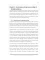
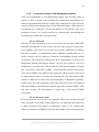
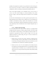
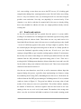
This work gives hints, tips and motivation for a test automation process – why
regression testing should be fully automated, and how (not) to do the process, what
kind of changes must be made and what must be avoided when automating these
tests; starting from fully manual testing, proceeding to the semi-automatic phase
where automatic scripts or macros, that must be executed manually, are used, ending
in a fully automated testing system where the test cases are always executed when
needed or wanted – without the need of a user starting the test case execution
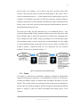
manually. This process is described in Figure 1-1.
Figure 1-1: Automation process of functional testing
1.3. Focus
The domain in which this test automation, continuous integration, and functional
regression testing project took place is Call Management, mostly in Call Resource
Handling sub domain, which are domains under the R&D of IPA2800, to be more
specific. This research will not pay attention to what testing tools and methods are
used in other areas inside the company, with the exception of describing the different
phases of testing, to clarify the whole development and testing process of the
software.
Chapter 1: Introduction
3
This work describes the functional and regression testing process; how this was done
earlier inside IPA, especially inside Call Management, and why it needed to be
changed, how the process has changed until this moment, and some ideas and
speculation are given on what the process will possibly look like in the future: what
would the ideal situation be like and what are the main problems and bottlenecks that
are blocking the way of getting there.
Mostly we will focus on the change that was made when new tools were taken into
use; key problems and their possible solutions; what should’ve been done in a
different way, what does the current situation look like, what should it actually look
like and how can that be achieved.
The goal of this work is to give a clear guideline on how a test automation process of
regression testing should be done; what kind of pitfalls there might appear and which
mistakes can be quite easily avoided, when the problems are recognized early
enough. These mistakes were once done and the problems recognized, and therefore
this documentation might become useful when there comes similar test automation
projects in the future, or when regression testing is wanted to be improved actually
anywhere, where a large piece of software is being implemented.
1.4. Research methods
Both literature and case studies are used in this work. A lot of the content is based on
the things learned during both the author’s studies at TKK and the work at NSN.
Some facts are also based on expert interviews; colleagues and other personnel here
at NSN. The literature part is mostly about the network elements in UMTS and their
roles, IPA2800 architecture, different types and methods of testing, including
functional testing and regression testing, test automation and continuous integration.
I’ve drawn most of the figures in this thesis work by myself with Adobe Photoshop
7.0 and all those that I haven’t, have separate references in their captions.
The case study is based on the results of a FRT part of a Continuous Integration
project that has been under development for about one and a half years now at Call
Chapter 1: Introduction
4
Management domain in Nokia Siemens Networks, and now the project finally starts
to pay itself back.
1.5. Structure
In the first actual part of the work, a general look on call connecting is taken and the
roles of UMTS network elements are explained in order to get a clear view what the
work is actually all about; where and for what kind of purposes is the platform
actually used.
Next, we’ll get deeper inside IPA2800 platform and the Call Management domain;
what its task is and what is implemented and tested here. This is followed by a
literature study about functional, integration, and acceptance testing, leading to a
description how this was done earlier in IPA. We’ll also look at the different phases
of software testing in IPA and see why each of them is important.
After that, a brief description is given about the functional testing tools that are used
at NSN and inside Call Management domain and which will be referred to later.
Next, when all terms and tools are becoming quite clear, we’ll move on to regression
testing and test automation; a literature study first, then the IPA2800 case – how this
was done earlier, traditionally, how we have moved on to this point with Continuous
Integration and CruiseControl and what are the benefits of those, what kind of
problems have been met, how should the automating of the tests be done, and what
kinds of things must be considered when working on these subjects. Also, “the
typical day of a test coordinator” is described; what it looks like in our environment
at the moment. Chapter 5 and Chapter 6 are the actual research and actions part of
this thesis work; in what this whole work is based on.
Sections 6.4 and 6.5 form the last part of the actual research, investigating about the
near and the far future of functional regression testing, continuous integration and
test automation. The latter is about the future of both functional and regression
testing in our environment; where are we going and what will the situation probably
look like some day. What are the trends and how could we make our FRT even more
efficient and easier than what it is today? Or is it even needed anymore if the code
Chapter 1: Introduction
5
itself will be “perfect” in that phase, thanks to all the quality enhancing tools that are
being published more and more all the time?
Chapter 1: Introduction
6
Chapter 2. UMTS architecture
UMTS is one of the third generation (3G) mobile telecommunications technologies,
specified by 3GPP, and it’s part of the ITU IMT-2000 family of 3G standards.
Compared to its predecessor, GPRS (“2.5G”), UMTS is much (about up to 50 %)
faster in data transfer, both uplink and downlink, which is needed to enable for
example high quality images and videos to be transmitted and received in the
wireless, mobile networks, and to provide an Internet connection with higher data
rates. UMTS uses WCDMA as its channel access method, and it supports up to
maximum theoretical data transfer rates of 21 Mbit/s (with HSDPA). [1], [2, Preface]
This chapter is an overview of the system architecture of UMTS networks, including
the roles of logical network elements and interfaces in a general level. All the phases
of the evolution of 3G (Release ’99 – Release 7) will not be gone through, instead on
what the architecture looks like now will be concentrated on, as well as what it is
capable of and how it works. These are explained in order to ensure that the
functionality and environment of IPA2800 platform, which is described in Chapter 3,
would be easier to understand. Especially the roles of RNC and MGW are the most
interesting ones.
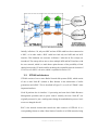
2.1. System architecture
The UMTS system architecture is close to the earlier, well-known architectures used
in first and especially second generation systems. Functionally, the radio network
elements can be grouped into UMTS Terrestrial Radio Access network (UTRAN),
which takes care of all radio-related functionality, and the Core Network (CN),
whose responsibility is mainly switching and routing calls and data connections to
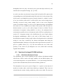
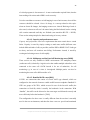
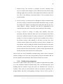
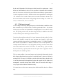
other, external networks. [2, p. 75] Besides these, User Equipment (UE), which
interfaces with the radio interface, is an important part of the system; to make a call
connection process complete, there must be a device that the user uses for creating
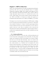
the connection. The whole system (composed by UE, UTRAN, and CN) is
represented in Figure 2-1, except the elements of IP Multimedia Sub-system (IMS)
functionality that enables a standardized approach for IP-based service provisioning
via PS domain, which is not covered in this thesis work.
Chapter 2: UMTS architecture
7
Figure 2-1: UMTS network architecture
Initially, in Release ’99, only one MSC and one SGSN could have been connected to
a RNC, or in other words a RNC could have had only one IuPS and one IuCS
interface. This limitation was overcame in Release 5 when the Iu flex concept was
introduced. The concept allows now to have multiple IuPS and IuCS interfaces with
the core network, which is a much better option because of the possibility of load
sharing between the CN nodes and for anchoring the responsible network element of
CN in case of a SRNC relocation, which is explained in section 2.2.3.
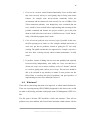
2.2. UTRAN architecture
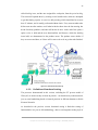
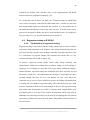
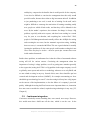
UTRAN consists of one or more Radio Network Sub-systems (RNS), which consist
of one or more Node B’s (known as Base Stations in the architectures of earlier
generations) and a RNC. This is described in Figure 2-2, as well as UTRAN’s most
important interfaces.
Node B performs the air interface L1 processing and some basic Radio Resource
Management operations such as power control. Actually, the term “Node B” was
originally meant to be just a working name during the standardization process, but it
was never changed after all.
RNC is the network element that controls the radio resources of UTRAN. It is a
corresponding element to what a Base Station Controller is in GSM networks; being
Chapter 2: UMTS architecture
8
responsible for the Node B’s in its area. RNC’s are described in more details in
section 2.2.3.
Figure 2-2: UTRAN architecture
The interfaces that are not concentrated on so much in this work, but which are also
shown in Figure 2-1, are Cu, which is an electrical interface between the USIM
smartcard and the Mobile Equipment (ME), and Uu, the (WCDMA) radio interface.
Uu is the interface that is used for the UE to access the fixed parts of the system, in
other words the first radio interface that is met when creating a 3G connection from a
user terminal. Iub, Iur and Iu(CS/PS) interfaces are described in the next section.
2.2.1. Iub, Iur, and Iu interfaces
The interface between a Node B and a RNC is called Iub. UMTS is the first
commercial mobile telephony system in which this interface between the controller
and the Base Station is standardized as a fully open interface. This means more
options for the manufacturers of these elements, which easily leads to improved
competition in this quite a narrow market. It is also likely that new manufacturers
will sooner or later enter the market concentrating exclusively on Node B’s. [2, p.
Chapter 2: UMTS architecture
9
78] This hasn’t happened yet anyway, at least on large markets, and probably even
won’t before the economic recession is over.
The other important interface inside UTRAN is Iur, which is also an open interface.
Although the role of Iur was originally mostly for allowing soft handovers between
RNC’s from different manufacturers, it also supports other services such as SRNC
relocation, inter-RNC packet paging, support of protocol errors and support of interRNC cell and UTRAN registration area updates, support of dedicated and common
channel traffics, and support for Global Resource Management.
Iu instead is the interface from UTRAN towards the CN, for example connecting a
RNC to a MGW. It might be either Packet Switched (IuPS) or Circuit Switched
(IuCS), depending on which part of the CN the RNC is connected to, as was shown
in Figure 2-1. The division depends on the requirements for the data; whether it’s
real-time (CS) or non-real-time (PS). IuCS is used for accessing external networks
such as PSTN and ISDN, which are accessed via MGW(s) or MSC and GMSC. IuPS
instead is for connecting to external PS networks, such as the Internet, which is
connected to CN via SGSN and GGSN. Iu is also an open interface, and it handles
switching, routing and service control.
There is also an additional third interface, Iu Broadcast (IuBC), which can be used to
connect UTRAN to the broadcast domain of CN, but we’re not interested in that
interface in this work.
2.2.2. IP Transport in UTRAN
Although ATM was the transport technology in the first release of UTRAN, it was
clear from the beginning that the increasing popularity of IP technology will lead to a
greater demand for this type of protocols, and another option had to be designed also.
IP transport was introduced in the specification of Release 5.
The frames of User plane Frame Protocol (FP) can also be conveyed over UDP/IP
protocols on Iur and Iub, and even over RTP/UDP/IP protocols in IuCS interface, in
addition to the originally defined option of carrying AAL2/ATM. Also, an option of
using SCTP directly below the application part is introduced. Anyway, the protocols
Chapter 2: UMTS architecture
10
used to transfer the IP frames are unspecified, for leaving more options for the
manufacturers and for not limiting the use of the interfaces of the lowest layers in
operator networks.
2.2.3. Radio Network Controller
As mentioned earlier, RNC is responsible for control of all the radio resources in
UTRAN. It interfaces with Core Network, usually with both MGW (earlier: MSC)
and SGSN.
Unlike in GSM systems, where Base Station Controllers (BSC) were connected to
each other only via Mobile Switching Centers (MSC), the RNC’s in UTRAN have
also direct connections. Also, in UMTS architecture(s), the transcoding unit is moved
to the Core Network, instead of doing this kind of media stream translations in RAN,
where this was done earlier. [3, p. 46]
A RNC that is controlling a Node B is called the Controlling RNC (CRNC) of the
Node B. It is responsible for load and congestion control of the cells in its area, and it
also executes code allocation and admission control of new radio links which are
established in those cells.
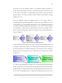
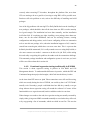
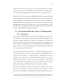
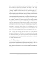
In case of a mobile UTRAN connection, which is using resources from two or more
RNS’s, the involved RNC’s have two separate logical roles; Serving RNC (SRNC)
and Drift RNC (DRNC), which are shown in Figure 2-3. In this figure, a soft
handover is made; the SRNC still holds the Iu interface after the handover, but it now
uses resources from the new Node B only, in another RNC’s (DRNC) control area.
The SRNC for a mobile is the RNC that is responsible for both the Iu link for the
user’s data transport and the corresponding RAN Application Part (RANAP)
signaling between itself and the Core Network. It performs L2 processing of the data
to/from the radio interface. The SRNC also takes care of basic Radio Resource
Management operations, such as handover decisions, mapping of Radio Access
Bearer (RAB) parameters into air interface transport channel parameters, and outer
loop power control. [2, pp. 79-80]
Chapter 2: UMTS architecture
11
Figure 2-3: An inter-RNC soft handover
The DRNC is any other RNC than the SRNC, which controls the cells used by a
mobile. In a handover process, UTRAN takes care of moving a UE to a new radio
connection. If a UE is transferred to a cell which has a different CRNC, this CRNC
becomes the UE’s new DRNC that allocates UE a bearer request of SRNC. Changing
the role of the SRNC to a different RNC, in case of e.g. moving to another MGW’s
area, is called SRNC Relocation [3, p. 28], which is also a task that Call Management
domain is responsible for, and into which we’ll get back in section 4.2.4.
2.3. UMTS core network architecture
Traditionally the tasks of Core Networks can be categorized mainly in the following
functions: aggregation of service provider networks, user authentication, call
switching and control, charging, and just being gateways to other, external networks.
Even though there were quite big changes in the radio access evolution (the radio
interface was changed to WCDMA) since traditional GSM networks, the CN of
UMTS did not face such big changes, especially in the first release. The structure
was inherited from the GSM core network, and UTRAN (as well as GERAN) based
radio access network was connected to a similar Core Network as earlier.
Chapter 2: UMTS architecture
12
In Release ’99, only one IuCS and IuPS interface were possible to be handled. Until
Release 5, which has an architecture that is mostly like the architecture used today,
the CN consisted of one Mobile Switching Center/Visitor Location Register, one
Gateway MSC, one Home Location Register (HLR), one Service Control Point
(SCP), and one Serving GPRS Support Node (SGSN) and a Gateway GPRS Support
Node (GGSN). This original architecture of Release ’99 is depicted in Figure 2-4.
Figure 2-4: Release ’99 UMTS Core Network architecture
The biggest changes that took place between Release ’99 and Release 5 are the
division of MSC into MSC server and MGW, as well as dividing GMSC to GMSC
server and MGW. Also the first phase of IP Multimedia Sub-system (IMS)
functionality was added for enabling the delivery of “Internet services” over GPRS.
Anyhow, this “vision” was later updated by requiring support of also other networks,
such as WLAN, CDMA2000 and fixed line. [4]
2.3.1. Network elements in CN
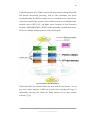
The full architecture of Release 5 UMTS CN is shown in Figure 2-5, with the
simplification that Home Subscriber Server (HSS) is shown as an independent item
without having all the connections to other elements in the CN.
The MSC or GMSC server is responsible for the control functionality of MSC or
GMSC, respectively. One MSC/GMSC server can control multiple MGW’s, which
allows better scalability of the network. The user data goes via a MGW, whose main
function is to provide UMTS functionality for the CS core. It is the endpoint for the
Chapter 2: UMTS architecture
13
ATM transmission from/to UTRAN, and it performs the actual switching of user data
and network interworking processing, such as echo cancellation and speech
encoding/decoding. So, MGW is actually used as a “translation device” that converts
(transcodes) digital media streams between different kinds of telecommunications
networks such as PSTN, SS7, and Radio Access Networks of Next Generation
Networks (GSM/GPRS/UMTS). MGW’s enable multimedia communications across
NGN’s over multiple transport protocols such as ATM and IP.
Figure 2-5: Release 5 UMTS CN architecture
SGSN and GGSN have remained almost the same from the early Release ’99 and
they cover similar functions as MSC but for packet data, including VLR type of
functionality, and they also connect the Packet Switched CN to other external
networks. [5], [6]
Chapter 2: UMTS architecture
14
Chapter 3. IPA2800 Platform
This chapter covers the basic functionalities and the architecture of IPA2800
platform, as well as the strict requirements that the platform has. The role of Call
Management domain is looked at a more detailed level, because of understanding the
essential purpose of this domain as well as its responsible functionalities, which were
also tested during this project.
3.1. Background, DX200
Nokia Siemens Networks continues the work that its predecessor, Nokia Networks,
did earlier as a developer of network elements. A network element is a complex
network of inter-connected computer units. The system consists of various computers
with different tasks of their own, communicating with each other via message
connections.
To enable real-time communication, the network elements must be capable of
performing real-time tasks; whenever a service request arrives, the system has to be
capable of performing the needed tasks in just a few seconds, including the sending
of an answer to the requesting party. This is made possible by three fundamental
mechanisms: using of main memory, concurrency, and a fast message connection. A
main memory based system means that all the information is available in a fast main
memory in each unit. Concurrency in this case means that multiple tasks can be
executed in parallel by different computer units and processes.
In early 70’s, the research and development process of DX200 started at Nokia
Networks and the first customer deliveries took place in the year 1980, in the form of
a Fixed Network Switching Centre (FNC). Later, multiple DX200 based products
have been developed, such as MSC, HLR and BSC. [7]
Anyhow, the capacity and performance of the old DX200 started to become obsolete
before the turn of millennium, and it was discovered that this system won’t be able to
handle the requirements of telecommunication systems of the third generation. This
was the need that started the developing of IPA2800 – a DX200 based system, which
is much more efficient and clearer of its architecture than its predecessor was. But,
Chapter 3: IPA2800 Platform
15
IPA2800 is not a substitute for DX200: it works in parallel with these old systems,
hand in hand, offering new resources and possibilities that are needed by the third
generation systems.
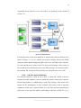
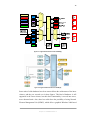
3.2. IPA2800 architecture
IPA2800 was designed to be much simpler than DX200 from the architectural point
of view. Block diagrams of the latest releases of IPA2800 are represented in Figure
3-1 (MGW) and Figure 3-2 (RNC).
The most relevant units, which can be found from both figures, are ATM
Multiplexing Unit (MXU) and ATM Switching Fabric Unit (SFU). The multiplexers
forward and adapt traffic of slower transmission speeds coming from outside to the
SFU, which connects the inter-computer ATM connections to each other.
The control functions are different kinds of computers, which take care of general,
internal controlling tasks and signaling to other network elements. Units of this kind
are ISU, CACU and VANU in MGW’s, ICSU and RSMU in RNC’s, and OMU in
both of them. The Operation and Maintenance Unit (OMU) is a very important unit,
which acts as a user interface between the user (operator) and the network element,
as well as handling of alarms in different situations. OMU has also a separate hard
drive, HDS or WDU, in which the program itself is located.
The Signal Processing Units (SPU) enable digital signal processing tasks, such as
speech encoding/decoding and echo cancellation. These units also vary depending on
whether the network element is MGW or RNC: DMCU’s in RNC’s and TCU’s in
MGW’s, which both contain several Digital Signaling Processors (DSP).
The system must also have some network interface units (often called Enhanced
Interface Protocol Unit, EIPU, or Network Processing Unit, NPU) for connecting
other types of data transmission methods (such as STM-1, E1, or Gigabit Ethernet)
and protocol stacks (IPv4, IPv6) to the system. [8]
Chapter 3: IPA2800 Platform
16
Figure 3-1: Logical network element view of MGW [8]
Figure 3-2: Logical network element view of RNC [8]
Some units of older hardware have been removed from the architectures of the latest
releases, and they are crossed over in these figures. This kind of hardware is still
supported in the latest releases, but their basic functionality is moved into newer,
more advanced units. Also, there has earlier been the possibility of using Network
Element Management Unit (NEMU), which offers a graphical Windows 2000 based
Chapter 3: IPA2800 Platform
17
user interface for managing the network element. Physically NEMU is a separate
computer that can be connected to a network element with an Ethernet connection. In
his thesis work, Mika Honkanen claimed [9, p. 5] that NEMU might replace the
MML connection totally in the future, but this is absolutely not the case; it was an
additional tool for network operators for managing their network elements on a
higher level, with which tasks that were not even possible to do with the traditional
MML connection, could’ve been done. NEMU was just a separate tool that could be
used for monitoring the network activity. Anyway, the NEMU concept doesn’t even
exist anymore in the latest architectures, but instead Operation and Maintenance
Server (OMS), a Linux based computer, is replacing NEMU in RNC’s. It provides
the same functionality as NEMU did earlier: for example configuration and
performance management, supervision, recovery, and fault management. Anyway,
these won’t ever replace MML but instead, a higher level software tool that uses
MML, could replace the traditional use of MML, some day.
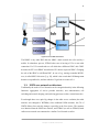
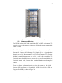
3.2.1. Hardware
Figure 3-3 shows what an IPA2800 based network element with one cabinet looks
like physically. A RNC can contain one or two cabinets, and a MGW might consist
of even three of them. Some Plug-In Units (PIU) can be seen in the figure in each
row (“rack” or “subrack”), some of them size of one and some size of two slots. PIU
is the physical card (computer unit) of a functional unit and it contains different
kinds of processors for different usages and different network interfaces (ports) for
its respective use. Every PIU contains an Ethernet port, to which a PC (usually via a
router) can be connected for a direct connection to this exact computer unit. This is
used for creating Service Terminal connections, which are described in section 4.2.3.
The evolution has also lead to the smaller physical size of network elements; the old
DX200 based network elements were significantly bigger than IPA2800 network
elements are today. The drawback with reducing size, in addition to increased
processing power, is the heat generated by the plug-in units, which leads to early
aging of the whole product. Therefore a more efficient cooling system had to be
developed for this kind of equipment. [9, p. 6]
Chapter 3: IPA2800 Platform
18
.
Figure 3-3: An IPA2800 based one cabinet network element [10]
3.2.2. Software architecture
The IPA2800 software itself is the same in both RNC and MGW environments. The
operating systems of the computer units on top of which the software runs are either
DMX or Chorus.
The whole IPA organization can be divided either into system domains, e.g. System
Start-up (SS), Capacity and Performance (CP), Security (SE) etc., or into functional
domains such as Call Management (CM) and Traffic & Transport (TT). The latter
dividing is generally the more used one, and it is used in this research also. The
functional domain based division also describes the part of software with which the
functional domain works, because these functional domains are also top level
features.
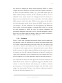
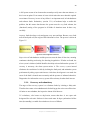
From the software implementation point of view, the software can be divided to
Systems (SYS), and further to System blocks (SYB), Service blocks (SEB), and
Program blocks (PRB), as shown in Figure 3-4.
Chapter 3: IPA2800 Platform
19
Figure 3-4: Software block architecture
Usually one team (one sub-domain under a functional domain) is working on one
SEB, containing a few PRB’s, so the partitioning can be done quite linearly. For
example Call Resource Handling (CRH), works on AARSEB (Adaptation and
Resource Management SEB), and Routing and Analysis works on RTASEB
(Routing Analyses SEB). Both of these teams belong under Call Management
functional domain, and SEB’s can also be categorized under their corresponding
functional domains (e.g. AARSEB in Call Management). This can be quite confusing
sometimes, because the teams are often referred to as their respective SEB’s, but
there might also be just a small part of a team working on some SEB. Also, SEB’s
are usually located in a few different computer units, for example PRB’s of
AARSEB exist in ISU/ICSU and CACU/RSMU, but some SEB’s are also present in
all units, for example AAPSEB (AAL Protocols). [10, Part I]
3.3. Availability and reliability
A very important point about network elements is that they are not just any kind of
computers that can be restarted whenever wanted. Network elements have very high
fault-tolerance requirements in general, because of their real-time nature; meaning
that they must be in active state all the time, waiting for inputs (calls) and being able
to answer to them. It is required in ITU-T standards (and by operators), that a
switching system has a downtime of less than about two minutes per year. This is
also known as “the five nines availability performance” (the probability of failure
less than 0.99999). [11, p. 14]
Chapter 3: IPA2800 Platform
20
A full system restart of an element takes nowadays easily more than ten minutes, so
this is not an option. Even restarts of some critical units take more than this required
two minutes. Recovery in case of any failure is an important task, in both hardware
and software faults. Redundancy (section 3.3.1) of hardware helps to tackle this
problem, but this means that because the system must be very fault tolerant, the
(functional) testing of the program in all kinds of situations must be done very
carefully.
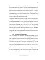
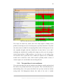
Anyway, faults do always exist and appear every now and then. Because every fault
must be analyzed well, the origin of the fault must be clear. The process is shown in
Figure 3-5.
Figure 3-5: Fault management architecture
Supervision of both hardware and the processes must be done all the time, meaning
continuous checking and testing for detecting irregularities. If faults are found, the
alarm system is informed, which identifies the faulty unit and informs the operator. If
recovery is necessary, the alarm system notices it. The recovery system instead
eliminates the escalation of a fault by isolating the faulty unit, and maintains system
performance by taking a spare unit into use. After that, the diagnostics are made: the
cause of the fault is located more accurately and the operator is informed about this.
Diagnostics also informs the recovery system if the unit may be taken back into use.
3.3.1. Recovery and redundancy
The target of the recovery system is to eliminate faults by isolating a faulty unit.
Therefore there must exist redundant units for backing up the active ones all the time.
All units are not redundant, but in practice almost all of them are.
2N redundancy, also known as duplication, means that there is one spare unit
designated for each unit. Software in these units must be kept synchronized all the
time (hot-standby), to enable fast switchovers in case of failures.
Chapter 3: IPA2800 Platform
21
N+1 redundancy, also known as replacement, means that there are one or more units
designated to be the spare units for a group of units. Resources are allocated only for
the active units, and a spare unit can replace any active unit in the group. This also
means that the switchover is slower than in the previous case, because it requires
warming (cold-standby).
SN+ redundancy means load sharing. There are no spare units, but a group of units
acts as a resource pool, from where the resources can be picked. If a few units are
disabled, the whole group can still perform its functions. The method for selecting
the unit from the pool varies; it can be based for example on least-loaded principle,
or just round robin. For example DSP resources are used from DSP pools.
The availability of the functional units that are managed by the recovery system is
controlled with unit states. Functional unit state consists of two parts: main state and
sub state. The main state tells the activeness of the unit: is it in “normal”, active state,
is it a standby unit, or if it’s not working at all, for example. The most common states
are Working (WO), Spare (SP), Blocked (BL), Test (TE) and Separated (SE). The
sub state instead tells (after a restart) whether the unit has achieved full functionality,
if it’s totally out of use, or hardware doesn’t exist at all. The most common sub states
are Executing (EX), Restarting (RE), Updating (UP), Idle (ID), Out of use (OU), and
No hardware (NH). The main state and sub state form the actual unit state together. If
a functional (active) unit is for example in its normal state, it is in state WO-EX.
Other possible states are for example SP-UP, BL-ID, SE-OU, and SE-NH. There is
also an additional field called unit info, which tells for example in which phase of a
restart the unit is. [10, Part III]
3.4. Call Management domain
We’ll take a deeper look into Call Management domain to clarify the tasks and
responsibilities that are implemented and tested here. This is just a general overview;
the actual functionality and responsibilities are described more in Chapter 4.
Call Management domain is responsible for, as the name already says, all call related
operations, from resource configuration to resource allocation. Call Management is
Chapter 3: IPA2800 Platform
22
the main interface for Call Control applications. This functional domain can be
divided further into three sub domains: Call resource handling domain (which will
mostly be focused on in this thesis work), Routing and analysis domain, and Signal
processing resource management and services domain. In section 3.3 the recovery
actions were discussed, and even though the actual recovering is not among CM’s
responsibilities, the call-related actions during the recovery are; for example when a
unit fails while handling some call resources, it must be taken care that the call will
not drop if a stand-by unit exists for that specific unit.
Call Resource Handling (CRH) handles the needed software to setup and release
switching resources for calls. The nature of CRH is very dynamic; IPA2800 is
capable of establishing hundreds of calls in just one second. Basically, the calls can
be divided into two resource models: two-sided calls and multisided calls. A twosided call means the traditional type of calls, with up to five “sides” (incoming,
outgoing, pre-allocated IN and OUT, and secondary IN). This model is used in RNC.
Multisided calls instead are for call conference purposes (multiparty), where there
are no “sides” in the calls, but each leg can have multiple services (tones,
announcements etc.), and where almost any kind of topology is possible between the
legs. This model is used only in MGW’s.
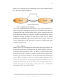
3.4.1. Leg and virtual leg concepts
A leg is an abstraction of the real resources, where the details are hidden from call
resource management; it only knows the type of a leg (e.g. AAL2, TDM, RTP/IP,
IuPS), its identifiers and the connection point. The leg concept is used to simplify the
logic in CRH – the logic is not leg type dependent. The connection principle of legs
is very flexible; any type of leg or service can be connected to any type. Legs and
services have special connection points, which can be either termination points or
DSP services. The connection between two legs is called a leg connector. This is
visualized in Figure 3-6.
By virtual legs is meant internal or temporary terminations in MGW’s. Virtual legs
can be converted into tones or other similar services (realized), overwritten with
normal legs (replaced), or connected to another virtual leg. From the call control
Chapter 3: IPA2800 Platform
23
point of view, virtual legs are seen as normal legs, so they can be connected to other
legs, tones can be applied normally, etc.
Figure 3-6: Two legs connected
3.4.2. Logical service concept
Call resource management may also have logical services, which are abstractions of
single services with no starting point. Such services in IPA2800 are Macro Diversity
Combining (MDC) and Conference Bridge. MDC is a RNC related user and control
plane function that combines the signals from a mobile station and chooses the best
composition of quality parameters, for improving the quality of a call without
increasing the transmission power of the mobile station. Logical services are
reserved automatically by CRH when they are needed, for example when a third
subscriber is added to a call.
3.4.3. Subnets
Subnets in RNC’s are for enabling non-real-time (NRT) data traffic. Basically, this
means that there must exist GTP subnets inside the element, which are ATM crossconnections between GTP unit(s) / EIPU’s and DMPG’s, to enable IP traffic (IuPS)
between SGSN and RNC. Subnets are created in a system restart (not anymore when
the first leg is created, as mentioned e.g. in [10]), and released only in unit/system
restarts. Subnets in MGW’s, which were Virtual Channel Connection (VCC)
networks for IPoA traffic, are not used anymore with the new hardware; they are
replaced by EIPU functionality instead. It seems that the (GTP) subnets may be
removed from RNC too in the future, because there exists a similar EIPU
functionality in RNC’s also. [Kor09], [Til09]
Chapter 3: IPA2800 Platform
24
3.4.4. Signal Processing service
The DSP utilization is modeled in a centralized unit (RSMU/CACU). The model is
based on a signal processing service that has certain capacity counters, defined by the
application. Call Management is responsible for the DSP unit selection in both
RNC’s and MGW’s. The selection is done based on the modeled estimation of a
DSP’s real load. DSP-services can be either inside a leg (e.g. AAL2+DSP leg), or
just as separate services (e.g. MDC-service).
DSP pools were mentioned earlier in section 3.3.1. Call Management can limit the
supported services in certain signal processing units, e.g. dedicating a selected set of
DSP’s for high speed services in RNC. This pooling affects the DSP unit selection:
e.g. resources for AMR calls are first tried to be picked from the primary pool, but if
there is not enough capacity available, a secondary pool will be used instead. The
pool configuration is static; the pools are pre-defined and the operator just defines the
proportion of the pools. [10, Part VI]
Chapter 3: IPA2800 Platform
25
Chapter 4. Functional and regression testing in
IPA2800 platform
This chapter gives a description of what functional testing and regression testing
actually are and what are the testing processes like in IPA; what is done in practice
and what kind of functionalities are in Call Management’s responsibility area. Also
the most important functional testing tools used are described. But at first, as
functional testing is generally not known as functional testing in literature, we’ll take
a look at other, more general terms with similar meanings.
4.1. Integration and acceptance testing
Integration testing (sometimes called Integration and Testing or I&T) is basically a
phase or an activity in which parts of software are combined together and tested, that
they work also as a group. Usually, unit testing is done for the different parts, then
integration testing for small groups of units that interface with each other, and finally
the whole system is tested, in some kind of a system testing/verification phase.
Integration testing, as well as the functional testing done inside NSN, is so called
black-box testing, meaning that the user can’t really see inside the program; he only
sees the user interface, inputs, and outputs – using the program should not require
any knowledge of the inner design code or logic. The purpose of integration testing is
to verify performance, reliability and functional requirements, placed on major
design items (groups of units or assemblages). Different types of integration testing
approaches are for example Big Bang, Top-down and Bottom-Up, or Sandwich
testing, of which each just takes a different approach from where to start the testing
and where to end; the lowest or the highest level components first.
Acceptance testing in so called traditional disciplines, such as engineering, is blackbox testing performed on a system with for example software and lots of mechanical
parts, prior to the delivery of the system. Some other names found in literature for
this are functional testing, black-box testing, release acceptance, QA testing,
application testing, confidence testing, final testing, validation testing, or factory
acceptance testing. In software development, acceptance testing is usually
Chapter 4: Functional and regression testing in IPA2800 platform
26
distinguished into two parts: one done by the system developer and one by the
customer (User Acceptance Testing). [12, p. 24-25]
As can be seen, there was functional testing in this list, but this still is quite not the
corresponding term to the functional testing of this work: this is only one part of the
whole system, even though this one part (a network element) is a complex “system”
of its own, and the system itself is verified (SyVe) later on the testing process.
Generally, acceptance testing means running a suite of tests on the completed
system. In acceptance testing, as well as in our functional testing, each individual
test, known as a case, should test one feature of the system, and will result in a
boolean outcome: a pass or a fail, with no degree of success or failure. The test
environment in acceptance testing should be as close to the anticipated user’s
environment as possible; the test environments used at NSN are explained more in
section 4.2.3. Acceptance testing is also clarified more for case of agile software
development methodologies, which is also used at NSN (Scrum mode). It is
described that acceptance testing in agile software development refers to functional
testing of a user story, executed by the software development team during the
implementation phase, and these are also often used as regression tests (section 4.4.1)
prior to a product release [12, p. 30]. This also matches the case of this work
perfectly, if user stories are just changed to use cases, which don’t necessarily
originate from customers.
4.2. Functional testing in IPA2800 platform
4.2.1. A brief introduction to Scrum
This introductory part is about explaining an agile software development method
called Scrum, which is used at the target company. All the different phases, like
reviews and retrospectives, are not described here – we’re just focusing on the basic,
top-level idea of Scrum instead, like how tasks and items get done etc.
The description of one sprint is given in Figure 4-1. A sprint is a time interval of
usually one month, where certain items should get completed. These items are
selected from the product backlog, which the product owner holds. The items are
Chapter 4: Functional and regression testing in IPA2800 platform
27
called backlog items, and the ones assigned for each sprint, form the sprint backlog.
The team itself expands these by creating several smaller tasks, which are attempted
to get done during a sprint. A scrum is a daily meeting, which should last for no more
than 15 minutes, and is usually performed without chairs. Every team member takes
his/her turn one after another, to tell what he/she has done since the last meeting, has
he/she faced any problems, and what will he/she do next. At the end of the sprint, a
sprint review is held and the new functionalities and features, which the backlog
items hold, are demonstrated to the product owner. The product owner decides if
they are correct and done, or if there still is some work to do to get the tasks finished.
Figure 4-1: The basic idea of Scrum [13]
4.2.2. Definition of functional testing
The processes demonstrated in this section, excluding the FT process model of
Waterfall, are shown as they are done in practice – not based on any written material;
just my own handwriting based on learned practices in different domains at Nokia
Siemens Networks.
As described in the previous section, functional testing is black-box testing of
functionalities in a pass-or-fail-methodology, done as an integration testing style of
Chapter 4: Functional and regression testing in IPA2800 platform
28
an activity; not for the complete system as in acceptance testing. In IPA2800, a
feature (whose functionality is tested), is a functional entity that is visible for a user
of the system. The features are implemented using internal services provided by
program blocks. The features usually consider software and hardware working
together. [14, p. 23]
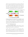
From the traditional software development point of view, using V-model or
Waterfall model, functional testing could also be done in a quite difficult way. This
would include a lot of documentation (Waterfall), as well as redundant planning and
reviewing, preliminary testing and final testing. [15, pp. 38-39] At least on paper,
this sounds like a complex process, which develops a lot of extra overhead. The FT
process of this previously used model, from about the turn of the millennium, is
shown in Figure 4-2.
Figure 4-2: The old FT process model (modified from [15])
At least nowadays when Scrum mode is used, in practice the preliminary phase can
be forgotten, and the three separate reviews shown in this old model can be replaced
by just one, final review. The three main phases of FT in practice are now: Planning,
implementing and executing the test cases, and a final review. This process is shown
in Figure 4-3.
Figure 4-3: Agile FT process model (in practice)
As a basis for the planning there usually exists a Feature Requirement Specification
(FRS). At this point, one can assume that the implementation of the feature has been
planned already, and implemented already or being implemented at the same time as
the FT cases. The planning itself is a quite short meeting inside the team; in this
Chapter 4: Functional and regression testing in IPA2800 platform
29
phase the feature itself should be clear and understood, so the test cases shouldn’t be
too hard to be implemented. No documentation or reviewing of the “test plan” are
needed; something might be drawn on paper just for clarifying the case. If new cases
are needed for an old feature, the “planning” is in practice just deciding who writes
these new test cases, if the feature (and the old cases) are clear.
Usually the strategy of implementing the test cases at the same time with the actual
implementation of a new feature is used, so the FT cases should be quite ready at the
same time as the actual programming is done. When done in this way, when e.g.
some final outputs can’t be seen before the code implementation is done, minor
changes might have to be made to the FT cases afterwards also. The implementing
and executing was put in the same phase, because often some parts of the macro are
executed before the whole test case is ready, e.g. some sub case (a function or a
method that is called from another case) that is not part of the feature itself, but is
useful when testing it, such as reading unit states (of the functional units of the
network element) from a printout and saving them into variables.
The final review is related mostly to new features. The functionality of a new feature
is demonstrated to the product owner in a sprint review, if this feature (backlog item)
is done. The product owner checks if the feature has all the wanted functionality
specified in the FRS and decides whether the team gets the backlog task done or not.
However, if there is uncertainty about the test cases even in case of old features, they
can be reviewed with a person or group to make sure that the test case does what it
should be doing, and everything goes right.
4.2.3. What in practice
The service terminals of computer units of a network element form the most
important outer interface for testing. Internal actions of the computer units can be
investigated and controlled via a service terminal connection, as well as doing
mandatory setup actions for the testing. The service terminal connection is a user
interface designed for system experts. The other important outer interface for testing
is the MML (Man Machine Language) connection of the MMI system (Man Machine
Interface), with which the commands implemented in MML programs (program
Chapter 4: Functional and regression testing in IPA2800 platform
30
blocks of the system) are executed. The MMI system and the MML programs
together form a user interface for the operator. [14, pp. 25]
In practice, functional testing of IPA2800 platform is using the MML and service
terminal connections via Telnet, and giving MML or service terminal commands
which execute the wanted tasks. The commands can look quite difficult to
understand for people who aren’t familiar with the system, a service terminal
command could be for example Z3RTSC:ICSU-0:102,,100,100,2, which starts
dynamic mass traffic to be running in unit ICSU-0 with wanted delay and length
parameters (also routing, codec, bit rate and other traffic parameters are given before
this).
Real, full network elements are not used so much in testing in this phase, because
they are very expensive, and all their requirements (e.g. capacity) aren’t even needed
in these “small” tests. That’s why there exist test environments, or test benches,
which are simplified versions of real network elements; they have the same
functionality, but they’re much smaller and they have less Plug-In Units of each kind
(e.g. two Signal Processing Units instead of 30). All the units needed for different
features are available anyway.
Different kinds of software tools can be used for FT, but the simplest way is to take a
Telnet connection to a test bench and write the commands to the terminal window.
Anyway, because the use cases often require even hundreds of commands, macros
are usually used (test cases). Before any “real”, decent FT software tools existed, this
was done simply by copy-pasting the commands from a text file to the command
prompt. Nowadays, the macros are executed with different kinds of software tools
that can include more or less programming; which makes the macros more flexible
for generic use, easier to read and follow (variables, keywords), and even shorter
than just giving all the commands (loops). Different software tools for functional
testing are represented in section 4.3.
Chapter 4: Functional and regression testing in IPA2800 platform
31
4.2.4. Functional testing in Call Management domain
Tasks and responsibilities of Call Management domain were described earlier in
section 3.4. Next we’ll take a more detailed look at what kind of functionalities are
actually implemented and tested here. Besides these mentioned case types, there are
several test suites concerning functions of some individual features, related mostly to
load sharing type of functions. Creation and deletion of GTP subnets, which were
described in section 3.4.3, are also tested by e.g. restarting units, and checking that
the subnets get released and re-created correctly.
4.2.4.1. Call cases
Basically, the most important test cases to succeed are the call cases in both RNC
and MGW environments. If some of these cases fail, some leg type or some service
won’t probably work. Every use case and every possible combination of different
legs must be tested. A configuration (routes, endpoints, signaling links etc.) is
always created to the test benches to match the corresponding network element
environment, and naturally the routing inside these configurations is a task of Call
Management (Routing and Analysis domain). The call cases consist of a set of all
combinations of possible legs, such as Iub-IuPS (GTP tunnel situations), IP based
Iub – Iur in RNC or Iu-IP BB, A (TDM) - Iu Data in MGW, and some more special
cases such as HSDPA. Also different traffic parameters and bit rates are used, as well
as using different orders in creating and connecting the legs and allocating DSP
resources or DSP services either in the leg creation phase or adding them separately.
In some cases, the traffic parameters and bit rates must also be able to be modified
afterwards. Handovers in both network element types and relocations in RNC’s must
also work correctly. The functionality of virtual legs is also tested in MGW
environment.
4.2.4.2. Recovery cases
Recovery action test cases are also very important. These cases test that calls (and
static or dynamic mass traffic) remain connected in e.g. functional unit switchovers
or faulty switchovers that happen in spontaneous restarts, or for example link
failures. In switchovers of RSMU/CACU units (hot-standby units), the warming time
Chapter 4: Functional and regression testing in IPA2800 platform
32
of critical programs is also measured – it must remain under required limits, that the
interworking with various other PRB’s works correctly.
It is also tested that no resources are left hanging in case of unit restarts, where all the
resources should be released. Owner id change is a concept related to this topic:
when an Owner Id changes, the hanging resources are cleared. Blocking of units is
also tested, so that new calls can’t be started using the blocked unit, but the existing
calls remain connected until they are finished (state transition BL-EX -> BL-ID).
These are the main principles for functional testing of recovery actions.
4.2.4.3. Capacity and performance cases
Capacity and performance also have requirements that must remain above certain
limits. Capacity is tested by simply creating as much mass traffic (different cases
include different kinds of calls) as possible, until the DSP or RSMU/CACU loads get
too heavy and new call creations start failing. Performance instead, is tested by
creating and releasing masses of calls rapidly.
4.2.4.4. Multiparty and On-Line Call Monitoring cases (MGW)
These services are only available in MGW environments. The multiparty feature
(conference calls) is basically a logical service that enables multiple subscribers to be
connected to the same call. OLCM instead is for use of authorities, for call
monitoring e.g. in case of a crime is investigated. Multiple parties can also be
monitoring the same call or different sides of it.
4.2.4.5. Bundled N-CID cases (RNC)
N-CID’s are connections that consist of several AAL2 type channels, which are
configured to the network element to enable traffic between endpoints. Bundled NCID’s are groups of N-CID’s, which are used in case of the last mile traffic (the
connection to Node-B), which is usually the bottleneck in the connection. With
“bundles”, the traffic can be directed to the same target and allocated correctly and
more efficiently before the bottleneck. [Til09]
The configuration for these cases is totally different from the one that is normally
used in the test environments, and therefore these cases are special and mentioned
Chapter 4: Functional and regression testing in IPA2800 platform
33
here separately. The regular configuration must be removed and the bundled NCID’s created before running these test cases, and this is a bit of an issue when
running automated tests. We’ll get back to this problem in section 6.1.2.
4.3. FT software tools used in Call Management
4.3.1. Holistic Integration Tester (HIT)
HIT is a tool used for testing of the internal services of DX200/IPA2800 platform.
Basically the idea is connecting the user’s work station to a test environment via IP
connections and possibly serial port numbers too, after which the wanted tests can be
ran. HIT is still absolutely the number one testing tool at NSN, as it has been for
about a decade now [14]. [16]
The original idea of HIT was, in addition to what could’ve been done via any Telnet
client, to run specific HIT macros for the testing. HIT macros give inputs to the
system, which are also printed to the terminal windows along the execution, and
outputs can be handled in a wanted way. Anyway, the test macros mostly consist of
MML or service terminal commands, so knowledge about them is required for being
able to implement the macros. What these macros do, is basically functional
(integration) testing of one network element, which was described in Chapter 4. HIT
macros can also be interactive, by e.g. asking some variables during the test case
execution, or freezing the execution totally until the user wants to continue it (called
“pause 0”).
These clumsy HIT macros are nowadays almost totally replaced by more intelligent,
easier and/or more efficient tools and languages, but HIT itself is still in a very wide
use – used as an easy, quick and versatile Telnet client for handling multiple
connections to the same test environment (different service terminal connections) at
the same time. The connections are used for manually executing some tests, creating
or removing needed configurations, handling unit states, and other simple operations
which would not be reasonable to be executed by macros or scripts. In addition, other
tools such as Hipla (the next section) have been implemented on top of HIT, which
are still in quite a wide use in certain domains of IPA.
Chapter 4: Functional and regression testing in IPA2800 platform
34
4.3.2. HIT Platform (Hipla)
Hipla was implemented on top of HIT, for enabling easier writing of more flexible
test cases, that can still be ran on top of the old HIT. Hipla is implemented as a series
of HIT macros, which form Hipla’s own “programming language”, which is quite
similar to Basic languages.
The macros are very easy and quick to be implemented; the executable MML and
service terminal commands can be written as such to the text (“DAT”) file, instead of
some required overhead, as this has to be done in HIT macros. Also simple loops,
scanning the outputs, saving variables and their handling, such a string or arithmetic
operations can be done with quick and easy-to-implement commands. Hipla’s
strengths, compared to HIT macros, are definitely its flexible and quick macro
implementing; the result is less lines of code in less time, with more functions. [17]
4.3.3. HiBot and Robot Framework
4.3.3.1. Robot Framework
Even though Robot Framework is not really used in Call Management domain, it is
introduced here because Hibot – which is used instead – runs on top of Robot
Framework.
The most significant difference between Robot Framework (usually called just
Robot) and other FT software used at NSN is that Robot is open source software. It’s
released under Apache License 2.0 and its copyrights are owned and the
development is supported by NSN anyway. Robot is also designed for fully
automatic testing and one can’t actually see the execution of the test cases while their
being executed; only the pass/fail status of each. After the test case execution, an
xml/html based output is generated.
Robot is said to be a generic, keyword-driven test automation framework for
acceptance level testing and Acceptance Test-Driven Development (ATDD). The
tabular syntax for creating test cases is easy to use and its testing capabilities can be
extended by test libraries implemented by either Python or Java. Users can create
Chapter 4: Functional and regression testing in IPA2800 platform
35
their own keywords either totally by themselves or by modifying them from the
existing ones. [18]
It is true that the “creating of test cases” is easy, but this actually means just creating
the test suites. If one isn’t familiar with Python programming, creating the keywords
becomes a major obstacle, even though Python is quite easy to learn and simple to
use as a programming language. In the beginning, when the keyword libraries of
IpaMml were very limited, the users had to create almost all the keywords by
themselves, which was probably the biggest challenge and the only reason why
Robot wasn’t taken into use everywhere. When there were the quite nicely working
Hipla cases and there really wasn’t time and resources for learning a totally new
programming language, some areas of NSN in Espoo continued using the old
practices – as people in Call Management still mostly do – Robot is not used here.
Also, people are used to seeing the test case execution all the time, as when running
cases with HIT or Hipla.
Anyway, the strengths of Robot are definitely its efficiency and flexibility – of
course because it uses a “real” programming language – and the html format output
reports that are very clear; marked with different colors, and the passes and fails of
all the individual test cases are very easily readable and understandable.
4.3.3.2. HiBot
The problem with Hipla was that the “report”, the output (called “T30”), of the
executed test cases was very hard to read because it was just a simple text file with
only the executed commands and printouts in it. If several, even hundreds of test
cases are executed with Hipla, there still is just one text file – with possibly even
hundreds of thousands of lines, and the separation of failed cases is quite
uncomfortable. Another problem is that Hipla is used almost solely here in Espoo
and people using Robot have been unable to execute Call Management’s Hipla cases.
In the summer of 2008, the development of a Python based Hipla – HiBot (Hipla
Robot) – started. Basically this means that all the HIT code of Hipla was first
Chapter 4: Functional and regression testing in IPA2800 platform
36
translated into Python code, and then some of the implementation and Robot
interfaces had to be programmed separately. [19]
As a result, there now are these “run_hipla_case” Python keywords, by which Hipla
cases can be executed as such inside the Robot framework – and the nice and clear
html format output reports are gotten after the execution. It is also possible now to
run both Robot and Hipla test cases in the same test suite. Also other tools, scripts,
and services designed for Robot can now be used with Hipla cases, for example for
IPA reporting server use, which is described more in section 5.3.
4.4. Regression testing in IPA2800
4.4.1. The definition of regression testing
Regression testing is any kind of software testing, which seeks to uncover software
regressions. Such regressions occur whenever some software functionality, that was
previously working correctly, stops working as intended. Typically regressions occur
as a consequence of program changes, and experience has shown that it is very
common that faults of this kind do appear. [12]
In practice, regression testing usually means either testing manually, that
functionalities, which were working before a software change, are still working, or
running a set of existing test cases that used to pass before making the changes.
Besides literature, regression testing does find faults quite often in practice too and
this means a simple fact – the implementing and testing of a new feature isn’t done
carefully enough. But after all, we’re just humans. In some cases, where the
regression test set is not so slow or difficult to execute, the finding of potential faults
is actually left to the hands of regression testing. This could anyway be also a good
practice, if and only if the test set is broad enough. In this case, the regression testing
done inside some Development Area (DA), is often not wide enough and the code
with defects goes to every part of the software development, which easily leads to
additional costs and using of resources in the form of investigating this new problem
somewhere, possibly at the other side of the globe. This problem is discussed more in
the next section.
Chapter 4: Functional and regression testing in IPA2800 platform
37
4.4.2. Test phases and different builds
“A build is much more than a compile, a build may consist of compilation, testing,
inspection, and deployment-among other things. A build acts as the process for
putting source code together and verifying that the software works as a cohesive
unit.”
–Martin Fowler [20]
Usually, a build means the compilation and testing of some unit or program block. In
this section, builds refer to Daily Builds (DB), which were originally designed to be
released once a day, and Common Builds (CB), which are released (frozen) about
once a month. DB’s and CB’s are compilations of the whole IPA2800 software put
together.
The software is developed all the time and these builds consist of verified, unit
and/or DA RT (Regression Testing inside a Development Area) tested program
blocks working together. Because changes to the code are made all the time, daily
builds are needed to be released very often. Common builds are frozen about once a
month, or actually once a sprint. The dates, before which all the code (all the new
functionality) must be ready and frozen are pre-determined: CCL (Service Block
Code Control List) day is followed by ECL (Environment Control List) day, after
which a new CB will be released. Next DB’s will be based on this CB. Anyway,
changes to CB’s are made weekly in form of pronto corrections, when faults are
found. These corrections are often quite critical and must be uploaded into the test
environments for all the functionalities to work. [21]
Before moving new program code to DA RT, the program blocks are unit tested,
which means verifying that the code itself works as a single unit. This is actually the
first phase of testing. After this, the code is added into a build and it gets “integration
tested” among other units; first in DA RT, which checks that other responsible
functionalities of the area still work correctly, and then in CB testing, so that other
parties can also verify that nothing has been broken and that everything still works
fine elsewhere in the software. The next phases are Performance Testing (PET) and
Chapter 4: Functional and regression testing in IPA2800 platform
38
System Verification (SyVe), where the real platform is tested in a real environment
that contains all the needed network elements, instead of testing only individual
elements like this is done in CB testing. This is the final testing phase before
releasing the product. Testing in the CB phase is very important: the Common Build
phase is the last opportunity to find and fix defects with decent costs, as can be seen
in Figure 4-4.
Figure 4-4: Costs of faults found in different phases, modified from [22]
The term CB here contains both DB and the actual CB testing. The latter one is
actually being concentrated on at the moment at Call Management, because even the
CB’s have often been of quite a poor quality level, even though they have been
getting better all the time. The goal has been for over a year now to move the
regression testing solely to using DB’s, and there has actually been many attempts to
do this, but there has been a few major problems.
Chapter 4: Functional and regression testing in IPA2800 platform
39
At first, as mentioned, even the CB’s, at the moment they are frozen and testing can
be started, have been in a poor condition; lots of corrections have been needed that
they would have worked at all. Then what about Daily Builds? Even the creation of
the basic configuration and the most essential, establishing basic calls, have often
kept failing, especially with early DB’s. Secondly, the author’s opinion is that before
it is possible to move to running the regression testing with DB’s, the maturity of
CB’s must achieve good enough level first, e.g. the maturity of all test cases should
be greater than 95 %. Now, when there still exists a lot to correct and finding defects
are found in CB’s all the time, this is not the right time for that change: again, this is
the last point to correct those defects without lots and lots of extra expenses. But, the
situation is looking very much brighter than for example a year ago, when even the
CB’s we’re hopeless in the beginning. The Continuous Integration projects and
Functional Regression Testing can be thanked for this, about which this whole thesis
work is about. This topic is described in more detail in Chapter 5.
Anyway, a feature team called A-team has started to run Call Management’s test
cases with also DB’s. They still have been of a weak quality usually, even though
they should be unit and DA RT tested correctly and their maturity is assumed to be
of a good level. Still, there often are some problems with basic calls, but perhaps the
biggest problem is with new features, which are added into DB’s, but which don’t
work correctly yet, or which are still incompatible with some parts of the rest of the
software. Some individual faulty features might cause even 50 % of all of the cases
failing, even though these are some separate functions. Also, this feature team has
had problems with their regression testing environment, working on their DB
projects, SVN (version control) connections, tool problems, just to mention a few.
There still exist a lot of problems and it’s definitely hard to try to fight them all at the
same time. [Tur09]
The management keeps asking every now and then, why isn’t Call Management
running its test set with DB’s, despite it was the order already about a year ago. If
some numbers tell that the maturity of the software is good, based on some unit tests
and internal RT of some areas, doesn’t mean that all the program blocks still work
Chapter 4: Functional and regression testing in IPA2800 platform
40
correctly when executing FT elsewhere, throughout the platform. But, now when
CB’s are starting to be on a good level, moving to using DB’s will be possible soon.
But there still exist problems to win, such as the difficulty of installing new build
packages.
One of the big problems with moving RT to Daily Builds has been the installing of
new packages, which should be done all the time when new DB’s reach a maturity
level good enough. The installation has been done manually, and the installation
itself often fails. If everything goes right, installing a new package takes about two
hours; one for the actual installation, and one for activating licenses, creating
configurations and doing patches, and of course configuring all the test automation
tools to use this new package. Also, when the installation happens to fail, it must be
started from scratch again, which takes even more extra time. This is a process that
definitely should be automated, if it is really wanted to move to using daily builds; or
else more resources are needed – someone to do this as his job. Well, while writing
this and really recognizing this problem, the author took the automation challenge.
This automatic package installation and configuration system is not in use yet, but it
will be soon. More about this in section 6.4
4.4.3. Functional regression testing traditionally in IPA2800
This section is about regression testing in practice in IPA R&D and Call
Management domain. To understand the differences in practice, which this FRT and
Continuous Integration project has brought, a brief look into the history is taken.
At the time when HIT macros or plain Telnet connections were still used for testing,
which was mostly during the time of DX200, one could say that “real” FRT didn’t
actually exist. Nowadays, people could think that how did they actually even get
along without decent regression testing, all around the software? Of course all the
functionalities were regression tested, but this could have taken its own time.
When changes were made to the code, the regression testing was usually executed by
simply either giving some MML commands manually to test whether they still work,
or by copy-pasting a list of commands, which were held in text files. This was the
Chapter 4: Functional and regression testing in IPA2800 platform
41
situation before the time of HIT, which allowed the use of real macros – the use of
actual test cases. A certain test set existed inside each group, team, or domain, which
was executed when changes were made to relevant program blocks. By that time, the
test set wasn’t very extensive, and faults could not be found as quickly as they are
found today – some minor faults or defects could have existed somewhere deep in
the program, and were only found in some unusual cases, e.g. some fault recovery
actions, where one fault lead to another. [Hup09]
Little by little, the test set became larger and a more extensive, adequate test set was
ready. It can still be quite annoying sometimes, when e.g. some group has made
changes to their code, and they don’t have an adequate test set to test whether the
changes have broken something else. When their changes are frozen and become
available for everybody, these possible defects are found anyway, and even quite
quickly, but the so called “easy” faults should be tested, found, and corrected already
in the DA RT phase of the responsible domain.
The author, as a representative of the Continuous Integration generation, is still
wondering about how things could have been working so well before decent
regression testing had been applied. On the other hand, by that time the software
itself wasn’t as large and complex as it is today, but the programming was probably
also done more carefully – exactly because of the lack of regression testing
capabilities. Nowadays the situation is that if one implements a correction with a bug
in it today, it might have been found already tomorrow by someone else, in another
domain. The attitude towards proper DA RT may have changed a bit, because CB
testing also finds these defects very quickly, so it “doesn’t matter so much” even if
there were some minor defects, for example. Also again, we’re only humans, and
often when e.g. doing a correction to some case, which must be done quickly and in a
hurry, it isn’t even possible to test the whole software again after the change is made,
and the defect might appear in some place that was totally unexpected at the moment
of implementation.
Chapter 4: Functional and regression testing in IPA2800 platform
42
Chapter 5. The FRT and CI project of Call
Management
This chapter is the most significant part of this research; all the information given in
the previous chapters are now described in action. We’ll start with a literature study
about test automation, continuous integration, and continuous integration server
tools.
The project of fully automated FRT is described in section 5.3: what was it like in the
beginning; what were the biggest problems, how were they planned to be solved and
how this actually happened, or were the problems even solved? Some very good
practices were found and these are also covered here.
In section 5.3.3, the actual work of the person responsible for his area’s FRT is
described – that the tests are executed correctly, that the automated testing works and
in case of problems, e.g. defects found, that he informs about these problems to the
responsible person or group.
5.1. Test automation
This section is mostly a literature study about test automation, in addition to
speculation about the practices at NSN. We’ll take a look of the benefits and
drawbacks of both manual testing and test automation, for giving some motivation
and background information for the whole test automation project.
5.1.1. Why to automate?
The traditional idea of test automation is to enable some tasks to be performed in a
much more efficient way – which could be even impossible in manual testing. Some
benefits of test automation from literature [23] are given below, for getting some idea
of what test automation is all about; what it was originally designed for, and why it is
used so widely around the world.
At first the most obvious task, especially in an environment where many program
blocks are modified frequently; running existing (regression) tests on a new version
of the program. The effort that the execution of a test set requires should be
Chapter 5: The FRT and CI project of Call Management
43
minimized: if a test set already exists, which has been automated for being executed
with an earlier version of the program, the effort for selecting a set of tests and
starting their execution should be a job of just a few minutes of manual effort.
Secondly, more tests can be executed more often with test automation. This simple
fact is a very big reason for automating the testing. More tests can be ran in less time,
which makes it possible to run those tests more often, which leads to a greater
confidence in the system.
What about running a test that simulates the input of 200 online users at the same
time? It may be difficult (but not impossible) to perform this manually, but by
automated tests, this kind of situation can be simulated very efficiently. So, the third
key point is that it might be even impossible to test some situations manually, and
this is where test automation comes in. Also some aspects that wouldn’t be noticed
by a real test user, can be seen by an automated test. For example something that
should appear on the screen doesn’t: the user won’t know to wait for it, but an
automated test notices this immediately.
The use of resources is a very remarkable point for the whole company and lots of
resources can be saved by using test automation. Let’s take a task of entering some
kind of same test inputs repeatedly as an example: this is a boring task for a user, and
he might do mistakes just because the lack of morale for the task, or because he’s just
a human. A greater accuracy is given by automating this kind of tests and these
persons are also now free to do something more useful.
The repeatability of the tests is improved significantly when using test automation:
the tests are repeated exactly in the same way every time (or at least their inputs).
Timing might be in a big role in some cases, which might be difficult to be executed
accurately enough when testing manually.
The automated test cases may of course be reused when implemented once. Every
time they are executed, a lot of time and resources are saved; even if the
implementation phase of the tests might take longer than just running a test
Chapter 5: The FRT and CI project of Call Management
44
manually, the automated tests usually start to pay themselves back in the long run.
Also, the same tests can often be executed for example with different hardware
configurations, which is an advantage concerning both repeatability and reuse.
After all, the biggest advantage of test automation seems to be the saving of
resources and time, and also leading to an increased confidence in the system,
because it simply is tested more deeply and more often than in case of manual
testing.
Of course these mentioned points are just from a general, top-level point of view.
When going deeper into the subject, there are different levels of test automation; for
example by semi-automatic testing is usually meant automated tests, but whose
execution is started manually. Instead, full automation means that the execution also
starts automatically, which is described more in the Continuous Integration topic, in
section 5.2.
5.1.2. Pitfalls of manual testing
Let’s take another point of view: why not to do it manually, even though manual
testing has been the cornerstone of software testing for decades. We’ll look at what
the major pitfalls of manual testing are, which should be avoided if possible. Five
statements are represented here, which are said [24, Chapter 3] to be the most
significant drawbacks of manual testing. This gives even more motivation for
automating the testing, fully.
1. Manual testing is slow and costly. It takes a long time to complete the tests
because the testing is often very labor-intensive. Of course this problem can
be tackled by increasing the headcount, but this increases labor costs as well
as communication costs, which doesn’t sound like a good option.
2. Manual tests don’t scale well. As the complexity of the software increases,
the complexity of the testing problem increases even exponentially, leading to
exponential amount of wasted time. Also, even with these increases in time
and costs, the test coverage will most likely go down, along with the growing
complexity.
Chapter 5: The FRT and CI project of Call Management
45
3. Manual testing is not consistent or repeatable. Of course, variations of the
tests are essential when testing the system. Different users may do the testing
differing slightly from each other, which might lead to different results of the
tests. This is also definitely an unwanted feature, if two executions can’t be
made identically.
4. Lack of training is a common problem, although not unique to manual testing.
Of course training is needed in both automated and manual testing. A trainee
for example isn’t capable of executing some testing tasks that are easy for a
senior engineer. Anyway, automatic tests that are implemented by an
experienced person can be executed by anyone with only a little training.
5. Testing is difficult to manage. In testing, there probably exists more
uncertainty and more unknowns than in the code development itself. There
must exist a sufficient structure in testing, or otherwise it will be difficult to
manage. Let’s take an example of a project whose schedule starts to slip: as
the software testing is done manually, it will take even more time, more
resources, and the whole project will slip even more from its schedule. It is
also said that a delay in getting the software from the developers to the testers
will lead to wasted resources. This is true, but can’t be applied in this case,
because of the fact that in Scrum mode, as well as in other agile methods, this
kind of developers-testers division isn’t used anymore.
After all, there are lots of drawbacks in manual testing, such as waste of resources
and time, ending to even worse test coverage than by using test automation. But, are
there any pitfalls in test automation? This is discussed in the next section.
5.1.3. Pitfalls of test automation
This section is quite similar to the previous one, with the exception that these pitfalls
are of test automation instead of manual testing. This is an interesting point, when
thinking about the amount of hype and praise test automation has received in
literature. There really are some drawbacks with test automation, especially if it’s
designed badly, and often in the beginning of taking it into use. We’ve got rid of
Chapter 5: The FRT and CI project of Call Management
46
these problems actually, and we’ll go through all of them from the NSN point of
view also. These top five pitfalls are from the same source [24, Chapter 4] as the
manual ones were.
1. Uncertainty and lack of control. Because of the automatic nature of testing, it
is commonly experienced that it’s hard for managers and other stakeholders
to know what is actually going on; what exactly is being tested and what the
process of test development and test execution is like. This might lead to
uncertainty, which might make test automation a risky investment. This
problem is quite interesting, because test automation was designed to reduce
uncertainty in the test results. With a lack of visibility, the actual value of test
automation is questionable. The author’s opinion is that the best solution for
tackling this problem is an official test coordinator for each testing /
development area, who knows where the testing is going and heading, and
who reports this information further, in addition to automatic reporting. This
concept is described more in section 5.3.3.
2. Poor scalability and maintainability. If not implemented properly, test
automation might solve the problem of manual test execution, but it might
also bring new problems, e.g. with maintainability. Maintainability is one the
oldest challenges of test automation, with which various companies are still
struggling today. The technologies, appearance and behavior of the systems
under testing, tend to change frequently even though that was not expected
originally, and the changes often appear with a very little warning in advance.
In these cases, test automation must be re-designed, and if generic and
modular test cases are not used, this might lead to a whole new testing
strategy. When the staff gets more experienced with test automation and it
has been used for a longer time, new cases will be a lot easier to add or
modify, because of the modularity everywhere. This is how the situation has
changed at the target company lately, when test automation has been learned
how to be used properly.
Chapter 5: The FRT and CI project of Call Management
47
3. Low test automation coverage. When asked how much of the test cases are
actually automated, most organizations will report figures in a range of 20-30
% or even less. This relates closely to the amount of work that the test
automation process actually takes, besides keeping test automation up to date
whenever the system changes. This low coverage is generally perceived as
disappointing by management, particularly when a lot of time and resources
are put into investigations and the actual automation work, and expectations
have been very high. At the target organization, this problem has been tackled
quite well, and the automation percentage is close to 100 % today – test
automation has been taken seriously enough into account already from the
beginning.
4. Poor methods and disappointing quality of tests. Usually bad automation
framework or architecture leads to these problems and the methods have a
poor level of reusability. In this kind of situation, the costs of developing and
maintaining the whole test automation process and its scripts will result in
higher overall costs, when either new tests must be planned again and again,
or the old ones have to be redesigned for new situations. Sometimes
problematic situations are met, where the automation process itself becomes
very difficult. When lots of resources are put into tackling the automation
problem, there might be no time to make more and better tests instead which,
after all, leads to a disappointing quality of the tests. This is a typical problem
in the beginning of moving from manual testing to test automation, but the
situation will most likely get better even sooner than what might have been
expected in the beginning. Some problems of this kind have been faced also
during this particular test automation project, and these are described more in
section 5.3.
5. Technology vs. people issue. When searching for “the perfect tool” for test
automation, one may find out that there actually isn’t a tool available that
would meet all his/her needs. It is also possible that the tool that would
otherwise be the best for solving the problem is too expensive to purchase
Chapter 5: The FRT and CI project of Call Management
48
and deploy, compared to the benefits that it would provide for the company.
It can also be difficult to convince the management that this really would
provide benefits, because these often are big investments after all. In addition
to just purchasing a new tool, it needs lots of training for the staff, and it
might be difficult to encourage the motivation of learning something totally
new; people are afraid of bad results, and that they will be blamed for the
mess. By the author’s experience, the resistance for change is always a big
problem, especially with senior experts, who have been working in a certain
way for years or even decades, and everything has “worked fine”. Well,
people in Call Management domain actually still use the old Hipla for writing
and executing the test cases, but the automatic regression testing, including
those test cases, is executed with HiBot. This was a good solution for actually
ignoring the problem at all; the senior people could continue writing their test
cases in the way they’re used to – the new system just executes these tests
inside another framework.
Besides these problems, an unfortunate fact is that the efforts of automated software
testing still fail for various reasons. Convincing the management about the
importance of testing is a huge problem, as well as getting more attention generally
to the (regression) testing itself. This is a big problem in the target company, as well
as globally; most reports and articles on technology advances cover only R&D, and
are not related to testing in any way. Instead of this, more focus should be put into
research and development and test (R&D&T); for example concentrating on “how
should this great technology be tested?” since the testing itself may have a big impact
on the success of the implementation, or also the failure of a company’s perceived
quality. Although the testing itself has become more important than ever, innovation
does not seem to consider the related, required testing technologies in any way. [25,
Chapter 4]
5.2. Continuous integration
Continuous technically means something that, once started, never stops. However,
this would mean that a build runs all the time, which is not the case. In the
Chapter 5: The FRT and CI project of Call Management
49
Continuous Integration context, continuous is more like continual; a process that
continually runs, polling for changes from e.g. a version control repository, and
whenever changes are discovered, a build script is executed. [20]
Continuous integration (CI) instead is a practice of software development, where the
members of a team integrate their work very frequently, usually at least daily,
leading to multiple integrations per day. Whenever an integration is made, it is
verified by an automated build (which includes testing) to detect possible integration
errors as quickly as possible; CI assumes a high degree of tests that are automated
into the software (self-testing code). It is often found that this kind of an approach
leads to significantly reduced integration problems, which leads to faster cohesive
software development. [26] This self-testing code approach hasn’t been taken into
use at NSN, at least yet. Anyway, it sounds like a good practice and definitely should
be given a try in the future. The problem is that some parts of the code are
unfortunately of very old design and it could be hard to take a totally different
implementation point of view in this phase, but the author’s view is that whenever a
totally new system will be designed, the approaches will be quite different from what
they are today.
This was just a top-level, general description of what CI actually refers to. In
practice, especially in case of a large piece of software, this often is a very complex
process, including various different phases of different kinds of testing, different
servers for certain tasks such as version control, data bases, test automation and some
processes related to functions of certain tools. Let’s take Nokia’s original product CI
infrastructure as an example, which is shown in Figure 5-1. In this figure, SWBT
(Software Build Testing) means basically functional (regression) testing.
The big picture of continuous integration in IPA means usually all the phases, the
whole structure of the software engineering practices, which were briefly described
in section 4.4.2, including all the different testing phases, as well as implementation
and integration, ending to a final product that can be shipped to a customer.
Chapter 5: The FRT and CI project of Call Management
50
Figure 5-1: Nokia’s product CI infrastructure [27]
5.2.1. Continuous Integration server
CI server is a computer that runs some CI software in it and, for example, runs an
integration build whenever changes in software are committed to some certain
version control repository.
The most known CI server tool is probably an open source software tool called
CruiseControl (CC) [28], which is a Java based, extensible framework for creating
custom continuous build processes. Although CC is written in Java, it is used on an
extensible variety of projects; for example Ant, Maven and Rake builds are
supported, of which Ant is used at the moment at NSN. CC is used widely at NSN,
all around the world.
Another, lately implemented CI server tool called Hudson [29] is raising its head
globally. As CruiseControl, Hudson is also Java based free software. Hudson looks
nice, the icons used instead of the traditional green “pass” and red “fail” colors are
really illustrative; e.g. different weather signs for illustrating the near history of the
succeeding of a project. Probably the biggest differences compared to CC are
anyway in configuring and adding new projects, as well as configuring the software
Chapter 5: The FRT and CI project of Call Management
51
itself: these tasks are made very easy to do, by simply clicking a few clicks.
CruiseControl was used in Call Management domain until the end of this project,
before pilot projects using Hudson were started, which are covered in section 6.4.
Both of these CI server tools support adding different kinds of plug-ins and third
party tools, which increase the level of modularity of these server tools greatly. New
plug-ins and widgets, which help in the customization of projects, are implemented
and published all the time. Basically, the most relevant ones are related to viewing
and publishing the results of certain files in a way one wants; without these it would
be mostly like just compiling the builds and/or running the tests and creating some
log files, which would have to be explored manually.
5.3. The automated FRT and CI project of Call Management
5.3.1. Background
This continuous integration project was started in Call Management already in May
2007. Back then, it was mostly concentrating on program block compilations, since
there was no proper automatic FRT software tool available yet. The idea was to
automate the builds, or in other words execute the program block compilations and
make sure that everything still works, after someone has made changes to the
program. Unit tests were also added later into the compilations projects, which are
also executed whenever a build is made.
The automated part itself is made possible by a continuous integration server and a
version control system. The CI server is polling all the time and waiting for changes
in some part of the software – a trigger that starts a build, that may consist of
compilation and/or unit testing, or just running functional regression tests. All the
actual code of the software, as well as the test cases, are held in a version control
system, which enables multiple persons to develop the software at the same time by
updating and committing the changes to/from a version control repository.
Since there are hundreds of FRT test cases and it takes a very long time to execute
them all, it is not possible in practice to run them whenever changes are made
somewhere. These builds are scheduled instead, simply meaning that they have a
Chapter 5: The FRT and CI project of Call Management
52
pre-defined test execution schedule, which was also shown in Figure 5-1. The
schedule means usually running the tests daily or weekly, in this case the FT projects
are always executed every night.
5.3.2. The progress of the project chronologically
Starting to execute the FRT tests automatically was a very significant milestone in
the history of IPA. As said in section 4.4.3, the regression testing was traditionally
done manually, executing a few test cases or even by just giving the needed MML
commands in a test environment, after changes were made in the program code. By
the time when CI servers were taken into use for the first time, there were some
automatic Hipla (section 4.3.2) test cases, but because of the huge size of the plain
text format reports, executing the FT tests really didn’t give any payback and those
attempts ended in failures. It would have required at least a whole day to go through
the enormous reports of even hundreds of thousands of lines of plain text, to get any
useful information about what was changed in the program code and what which
cases were failing.
Anyway, this kind of practice was done for over a year, until a new software tool for
functional testing was designed; HiBot (section 4.3.3.2), which would help to
overcome this kind of problems. Another solution would have been moving from
Hipla to Robot framework (section 4.3.3.1) when it was starting to show its
strengths, but the engineers who had been working for almost ten years with HIT and
Hipla macros wouldn’t have been satisfied; the world of Robot is totally different
and much more complex than what had been used to, and it also would have required
lots of training – and there simply wasn’t time and resources for that. By starting to
use HiBot, all the old Hipla test cases were possible to be executed in a new way; a
fully automated way, which gives a clear, illustrative report of the results – where all
the failed cases can be distinguished and inspected easily and quickly. After all, this
was the best possible solution to the problem, but lots of problems were faced during
the implementation and the actual commissioning of this FT tool.
At first, during the summer of 2008, all the old HIT based code of Hipla was
translated into Python language by a translator [30], which was implemented by Juha
Chapter 5: The FRT and CI project of Call Management
53
Kuokkala, a person who was (and still is) the main responsible for both Hipla and
HiBot software. The responsible would leave the company again after the summer,
and not come back until the next summer, as he always does. In August 2008, when
the Hipla and HiBot responsible left again, the translator was ready and the code was
translated into Python, but the code of HiBot still required a lot of manual job. It
simply is impossible to translate all kinds of functions automatically, such as IF
clauses, which can take so called by-reference arguments as their inputs in HIT code,
which is not supported in Python. Also, as Hipla used HIT’s Telnet connection
features, this needed to be implemented separately, which Kuokkala made in a hurry,
and got the connections working mostly before he left.
This was the point where the author, as a summer trainee with almost no knowledge
of Python programming at all, started to work with implementing and developing
HiBot. The only advantage of taking the author into this project was the fact that he
had at least some experience on the actual Robot framework and some close,
personal contacts to people that use Robot and Python all the time, which could help
in case of problems. Kuokkala instead was very familiar with Python programming,
but he didn’t have any experience on Robot, for example how the test suites were
implemented and how they were actually executed. But something that didn’t really
encourage for taking this project was Kuokkala’s words, concerning a data update
functionality, during the last days of the summer: “That will probably be an infinite
swamp to get it working.” [Kuo08]. Despite those not-so-supportive words, the tool
got working as it was designed, in only about few weeks. By this is meant that some,
simple Hipla cases were possible to be executed using HiBot, but most of the
functionalities still weren’t implemented or were very buggy.
In the beginning of January 2009, after the critical, major deficiencies were found
and fixed and the most relevant features finally started to work, it was decided to
start using HiBot in Call Management’s automated regression testing – in the
CruiseControl of Call Resource Handling team. This was designed to both find more
defects and possibly unimplemented functions in HiBot when running all kinds of FT
test cases with it, as well as finding real software faults in the IPA2800 platform
Chapter 5: The FRT and CI project of Call Management
54
later. This CI with HiBot pilot project was a big success, as defects in HiBot code
were found all the time. When it worked properly, HiBot was discovered to be a very
good and powerful tool for FRT in the CI concept. More and more test cases were
added to the FT project in CruiseControl, and finding all the bugs and missing
functionalities in the software was really focused on. Also some other teams inside
Call Management were interested in this new software and started their own pilots.
This lead to even more manual work with HiBot because those teams used lots of
Hipla functionalities – which weren’t in use at all in CRH – that didn’t work either.
Actually, almost every single Hipla command had at least some kind of a bug in it,
and they all had to be fixed one after another. Also, when adding old Hipla test cases
that might have had some functions related to manual testing, such as asking for
inputs during the execution, had to be automated. Some cases were also designed to
be executed individually and had some problems for example by leaving hanging
resources in the system, because of the missing decent teardowns of the cases, which
always affects the following cases in a consecutive execution. Also, some test cases
are very hard to be torn down properly in case of failures, and special conditions,
such as thinking about the text execution order, must be given for these tests. Making
the test cases really automatic and compatible with all the other cases isn’t the
simplest task. This automation process is described more in section 6.1.
The tool got better little by little and got more correctly working functionalities all
the time, but more critical problems were found every now and then – which
sometimes lead into crashes of the whole system, or just abnormal activity of the
software, which lead to failing test cases, which furthermore lead to lots of other
failing cases. These problems were mostly caused by the Telnet connections; the
poor Python implementation of HiBot for handling the connections. This lead to
waste of time and resources, when those failed test cases had to be executed over and
over again, just for getting the true results of some tested functionalities. Anyway,
these problems were of random nature, so the bugs were hard to find and it was hard
to concentrate on them – in addition to the still-quite-poor skill level of Python
programming of the author.
Chapter 5: The FRT and CI project of Call Management
55
There were also some limitations when using Hipla in the CI projects, which was
seen as a good opportunity for implementing the missing features into HiBot. A
major advantage when using HiBot in the CI projects, which was implemented, is the
possibility of running several projects at the same time in parallel. There are different
test environments for the FT of both the network elements (RNC and MGW), and for
testing with different releases of the builds. If all the test cases of all these projects
had to be executed consecutively, there wouldn’t be enough hours in a night; it
would take about 19 hours at the moment to run all the test cases of the current FRT
projects consecutively. As with new features usually, they aren’t working perfectly at
the first executions. This brought more problems and even more waste of resources,
when sometimes the projects got mixed with each other, meaning that for example
the test cases of some project were executed in another project’s environment, in
which they are impossible to be executed correctly. This feature took its own time to
get it working properly, and what was irritating was that this kind of faults also
happened only occasionally and it was very hard to find the reason for this at first.
The management heard about a concept of IPA reporting server that had been taken
into use elsewhere in IPA, which was designed for easy viewing of the test results of
different development areas. Call Management decided also to start using it, since
the concept sounded good. In principle, one might think about this as a simple
operation of sending the number of passed and failed cases, with some kind of a tag
of whose results they are, to the reporting server (via FTP), which publishes all the
results, arranged by the test case owner, and draws some chart and shows the history
of the results. This really wasn’t the case – about a dozen tags were mandatory,
which must had been included in the test suites, that the results were visible. It
would’ve been okay if the tags had to be added to the test suites just once, but no; the
mandatory ones changed every now and then, in addition to the ones that had to be
modified for example whenever starting to use a newer Common Build. After all, the
great idea of the easy-to-use tool for management level for viewing the results of
their responsible area, was turned into a documentation and statistics tool, in addition
to the original meaning, and they kept requiring more and more information about
the executed cases – this kind of information really isn’t interesting for the managers.
Chapter 5: The FRT and CI project of Call Management
56
This really took a big effort to get it working, and especially to maintain it there too –
which was again time and resources taken away from HiBot development.
When trying to focus on HiBot problems, there still were occasional problems with
the CruiseControl itself too, such as memory problems, when several CruiseControls,
which held several simultaneous projects, were running on a single CI server. There
were also problems with the configurations of the projects – sometimes the projects
started the execution by themselves, which really wasn’t supposed, or sometimes
they were not running at all. Another problem was that some projects can’t be built at
the same time, for example projects configuring the test environments – including
changing the target package to the correct one and doing system restarts – must be
executed before the actual tests can be executed. There was actually only one,
external person who was familiar with configuring the projects in the beginning, and
as one might guess, he was also very busy because of several “customers” with the
same kind of problems all around the company. It was very harmful, that when
HiBot would have possibly worked correctly, the environment didn’t. Later, the
author became familiar with these systems and learned how to configure them also
without help, but this took its own time of course.
These projects for configuring the environment for FRT were found to be critical,
because of the fact that the same environments were used at daytime for other tasks
such as implementing and testing new features, among other backlog related tasks.
Very often some test versions of some PRB’s were left in the environment or there
were some hanging resources left from the daily testing, which both lead to failing of
the FRT test cases executed nightly. The solution for this was to always create a
separate copy of the software package which is used only for CruiseControl
purposes, and implement a macro and a project, which change these packages active
always before running the actual FT projects. Proper configuring of the
environments, as well as the projects themselves, is a very important task.
Since the author, as a summer trainee, was the one responsible for the FRT part of CI
in practice and the one who went through the FRT execution results daily, the author
accidently took the role of the test coordinator of his requirement area during the
Chapter 5: The FRT and CI project of Call Management
57
winter. This was not planned, it just happened because no one else had as much
knowledge as the author had about which test cases are actually executing, which
cases are failing, where does the trend of results lead to, when to add new cases to
automatic FRT, when to start using new releases, and so on. The role and the typical
day of a test coordinator are described in section 5.3.3.
By this time, it was almost summer again, and there still were lots of problems with
HiBot, mainly concerning timeouts in connections, echo errors when reading outputs,
and prompt detection problems. Finally, the man who originally implemented the
Telnet connection handling functions of HiBot came back to work and started
working on these problems. It would finally be possible to execute FRT with HiBot
in Call Management’s CI environment, focusing on the actual CI tasks: to find and
fix defects in IPA2800 platform.
At that moment, the lately named test coordinator finally had time to focus on other
things also, such as developing the quality of the testing in practice and maintaining
the completeness and maturity levels high enough. Where the reporting server shows
only the history of daily passes and fails for manager purposes, the CRH team came
up with an idea of showing the history of all the individual test cases in an Excel
based table. All the FRT cases were listed already in an Excel sheet, so the basic
information was already available. The script for adding the results to this sheet was
quite simple to be implemented with Python, when the specifications were clear.
This script (Appendix A) searches the individual test case status from Robot’s XML
format report, based on the name of the test case, then examines if the Excel sheet
contains the same name in string format, and adds a green PASS or a red FAIL text
to a correct cell. An Excel sheet containing this kind of information is very
illustrative, and if some test case keeps failing continuously, it can be seen very
easily from this even with only a quick look, as can be seen in Figure 5-2.
Chapter 5: The FRT and CI project of Call Management
58
Figure 5-2: An Excel sheet of the individual test case results of a project
This script was found very useful, and it has really helped in finding critical
problems concerning test cases of certain projects, especially when there is only little
time and resources available for investigating all the results of all the projects. It was
also originally designed, that there should also be some kind of “error codes”
indicating into which kind of a problem did a single case fail; was it for example a
CruiseControl problem, a HiBot problem, a test case bug, or a real software bug.
This would’ve been a good idea, but it would have required a lot of additional,
manual work to add those codes, which would’ve probably ended in waste of
resources again, so it was decided to not start doing this task.
5.3.3. The typical day of a test coordinator
This section describes how the tests and their succeeding are actually monitored and
how defects are possibly found in the code in practice. This is described because of
understanding where to the project described in the previous section has lead the
testing inside Call Management domain, how much of the work is actually
Chapter 5: The FRT and CI project of Call Management
59
automated, what still needs manual working, and what kinds of things might still
need changes.
As told in the previous section, the FRT projects are executed every night. This is not
done at daytime because each of the projects last from six to seven hours and there
exists only a limited amount of test environments – so it is quite logical to execute
these tests by night, when no one else is (hopefully) using the environments.
In the morning, the test coordinator goes through the projects one by one, inspecting
which cases have failed and for what reasons. There are four different types of failure
causes:
1. A potential real defect in the latest changes of the software code
2. An existing, occasional problem appearing every now and then
3. External problems: problems with network connections or software tools
4. An error in a test case itself
In an ideal situation, all of the test cases would normally succeed, and failures would
only appear in case of real defects in the code. This is not the case in practice; some
test cases tend to fail more often than others and there are also external factors that
affect the testing, such as problems with network connections or problems with the
software tools used. In the beginning of this project in Call Management, more than
half of the cases were failing, so there was quite a lot of work when going through all
the failed ones. But since this project has been a great success, now only few of them
are failing, even though the total amount of test cases has increased significantly. Of
course it might be hard to determine whether some case is failing only occasionally if
it hasn’t failed before, or if this fault is a permanent one. Therefore, the cases failing
because of unknown reasons are often executed again in the morning – this usually
won’t take long, because the amount of them is normally quite small. Also, when
executing a certain test case again individually, it turns out if the nightly failure was
Chapter 5: The FRT and CI project of Call Management
60
possibly only because of some previously executed faulty case, which has to be
corrected.
The problems of random nature are the most difficult ones. If they won’t appear
every time, the situation might be very hard to reach again – which means it is very
difficult to find the cause of the problem, and even harder to find the possible
solution. These tests must be taken under supervision and wait if the faults appear
again. Sometimes, the problem might have been caused by an occasional problem in
some other test case, so this particular case won’t fail again, if the other problem is
resolved.
The external factors are probably the most annoying ones – it is known that the test
cases would pass correctly, but they are not because of some, sometimes mysterious,
external reason. When testing in big organizations and large software, various tools
are used together, as well as various network connections, and after all it is pretty
hard to get them all work correctly together, all the time. They can be informed about
the problem, if it is known what is the cause or where does the problem lie. But
unfortunately, these often are things that can’t be affected easily, or just by reporting
of them to someone.
The easiest and often most foolish errors lie in the test cases themselves. Fortunately
these bugs are often as easy to correct as they were to implement. Of course there are
different types of test case faults, possibly requiring even a total refactoring of a
whole test suite. We’ll get back to this kind of problems in section 6.1.2.
But, the most wanted, the actual reason for why regression testing is done at all, are
the real defects found in the software. After a failing test case has been executed
again and it is found that the problem still persists, the reason and the defective part
of software must be found. In some cases, for example calls of some certain type
may be failing because of an already familiar error code that might easily lead to the
right track when trying to catch the defective program block. It’s best to first check if
some new software corrections concerning this program block have been uploaded to
the test environment after the previous execution of this project. The uploading of the
Chapter 5: The FRT and CI project of Call Management
61
corrections is also done automatically every evening, if new corrections for the used
environments have been published. In this case, “the guilty” is found, but still it is
needed to collect some more information, as well as in case of still not knowing who
is responsible for this problem. Usually some computer logs are written when an
error appears, or possibly even alarms (section 3.3: fault management architecture).
At this point, usually someone in the responsible domain knows at least what this
error is about, or even what (or which PRB) might cause it. If not, more information
is needed, and the test case is executed again with message monitoring activated; this
collects all the wanted actual messages that are sent between different program
blocks, to the hard disk of the test environment. Usually some messages are captured
as default, and they can be sent to the person or group who is responsible for the
piece of software that probably is defected. Often, especially if the PRB is outside
one’s own DA, all the information that is needed for resolving the cause of the
problem isn’t known, but it is always comfortable to deliver at least some essential
information, even it is known that they will ask for more information. This kind of
information would be nice to know, for saving time and resources, already before
contacting the responsible people, and could be shared in for example wikis of each
area. This information might be something like giving information about which
commands must be given in case of a certain error.
The person or team responsible for some PRB should know what the messages are
designed to look like and usually it is quite easy to go through these messages of a
faulty test case to see what actually goes wrong, to perceive in which function the
defect really lies. Some people are able to just look through the messages in plain
text format, which means nothing but hexadecimals, but this requires a very long
background and wide knowledge of the PRB. Usually people use different software
tools for reading the messages in a format nicer for the human eye; where the
different parts of the messages are explained in plain English, and where it is much
more easier to outline bigger entities of the messages, or where all the messages may
be sorted e.g. chronologically or by the name of the message.
Chapter 5: The FRT and CI project of Call Management
62
After the reason causing the problem has been resolved, and new software
corrections are made, a test version of the PRB is sent to the ones who found the
problem. The failing test is executed again and checked if the correction works or
not. This test version is still used in that environment and the DA’s FRT test set is
executed with it, to see if something else has been broken by this correction. If this
leads to some other problems, this same sequence of operations is done again. It
often takes a few iterations before the first problem gets fixed, but “little bug-fixes”
of this kind don’t tend to break anything else usually.
If the amount of the failing cases is very big for some reason, and in the worst case,
in all of the different ongoing projects too, some tools for helping the analyzing are
very handy; for example the script for keeping track of the status history of
individual cases, which was represented in the previous section. This kind of tools
often help in conceptualizing the big picture or some smaller entities, for example
certain types of tests failing more often than others. Also, the test coordinator is not
(or should not be) responsible for resolving and correcting all the problems – that’s
why there is the team around him/her; who often are more familiar with certain
functions or PRB’s than the coordinator. The test coordinator should just be aware of
the situation, problems and corrections of his/her responsible area, and inform the
responsible people for the defective code or delegate the problems to people who are
the most familiar with them, as well as take care that milestones, usually concerning
completeness and/or maturity of a certain level in some release before the deadline,
are reached.
At some point (usually in a daily Scrum), the test coordinator informs his team, how
the test executions have gone and what kind of possible problems there are. Also, the
test coordinators are responsible for informing the persons responsible for the testing
of the whole release about the situation and problems, which is usually done weekly.
After all, all this requires quite a lot work, for both the test coordinator and the team.
The problem is that keeping the FRT in a wanted quality level is always left behind
other things; usually backlog tasks, because this is a separate part of all the other
R&D tasks. This leads to the problem of concentrating (the resources) on the right
Chapter 5: The FRT and CI project of Call Management
63
things. The top level management does want very good quality, but they often aren’t
aware of the resources that a decent (regression) testing would require; really
adjusting the focus sometimes onto the old functionality, instead of only focusing on
new features and their testing. As a suggestion to this problem, a good proposal
would be, possibly even organization-wide (F)RT sprints every now and then, in
which these tasks and all the projects running in CI servers, would be taken into a
good maturity level before designing, implementing, and testing all the new
functionalities again. Also, if the test coordinator is someone, who is responsible for
also the CI server and the testing tool, in addition to doing backlog tasks and
implementing test cases for new features, this simply is too much to take for one
person, and the use of resources should probably be reconsidered.
Chapter 5: The FRT and CI project of Call Management
64
Chapter 6. Lessons learned from the project
There are quite a lot of tips and tricks that were found useful during this project, as
well as problems and pitfalls that should be avoided in both automating the test cases
as well as configuring and maintaining the whole automated CI projects. This chapter
is about the discoveries; the good and the bad practices found during the project.
6.1. Automating FT cases
Making FT test cases fully automatic isn’t a task as easy as it sounds, especially in
case of automating old, manual test cases. Some of these points are applicable in
different kinds of testing and with different software tools, but some of them are
more programming language specific, because of the nature of Hipla macros is kind
of unique after all.
“Old manual cases” in this context mean tests that might for example ask some
variables during the test execution, or have infinite pauses, which the user may
interrupt whenever he has completed some needed tasks that have to be done before
the next phase of the test. This kind of tasks could be for example checking some
logs for certain errors, changing unit states, or starting more calls in case that the
existing ones are not enough, or just timing some action correctly, which “must” be
done by the user. Because there existed no such thing as fully automatic testing
earlier and the testing was done manually, there was a huge amount of test cases of
this kind in Call Management. This part isn’t very applicable for e.g. Robot cases –
which must be made automatic already in the beginning. But what is applicable for
any kinds of test automation, is the principle of a generic structure; if the situation,
the environment for example goes through some minor changes, this won’t either
affect the test case at all, or the case is easily modifiable to work with the new system
also. Hard coded values for example, in most cases, are a good example of very bad
test implementation: the case works this time, but if the system, the huge software,
changes a bit, the case won’t work anymore. In some cases, as in the bundled NCID
cases (section 4.2.4.5), the values don’t even need to be hard coded, but if some other
functionality changes a bit, the tests will fail. This mistake was mostly caused
because of the poorly implemented configuration, or not even poorly, but without
Chapter 6: Lessons learned from the project
65
obeying the modularity principle: the amount of the created bundled NCID’s was
actually the boundary limit below which these tests wouldn’t work in the future
because another, later implemented functionality would have required just one more
NCID to work correctly, to get those NCID’s distributed correctly to different
functional units working as a resource pool. If it would’ve been easy to add the
missing NCID to the configuration, this would’ve been done a long time ago.
Also, very poor implementations were found in many places in the test cases, for
example by assuming that a certain printout of a command remains the same forever.
A macro can scan the printout and read e.g. characters 2-4 from line number 3. A
better way to implement this would anyway be searching for a known string; a tag,
which possibly won’t change, and count the line and place (amount of words) away
from it, and do the scanning there. When using this kind of certain tags, and scanning
the whole words instead of characters, the test case is also a lot easier to understand
and change afterwards, if needed. Also, if the scanned word is for example the name
of a functional unit – even the name would change to a longer one, the test case
would still work when done in this way.
It was earlier said that in some cases, some tasks “must” be done by the user, for
example to time certain actions correctly. This was inside quotation marks, because
this was originally the easy way, especially when people were not so familiar with
“real” test automation. Almost all cases of this kind are anyhow possible to be
automated by reading some values and acting differently in different situations. It
was originally easy to just read some wanted value of a printout by human-eye and
give it as an input for the next function. The infinite pauses, “pause 0’s”, all had to be
eliminated and the functions be implemented in another, automatic way. The timing
instead, might mean for example waiting for some action to happen, and do the next
required actions just at the right moment. Well, these can easily be automated by
polling the situation frequently enough and acting at the right moment.
One very big issue that was faced during this project was forever-loops. As in Hipla,
loops are implemented by simply using basic-like GOTO (and GO_BACK_TO)
Chapter 6: Lessons learned from the project
66
commands, which enable jumping to a certain place (a row that includes a wanted
tag) in the macro. The following case works as an example:
[Step 1] Restart a functional unit
[Step 2] Check if it’s up and running again
[Step 3] If not, sleep a few seconds and GO_BACK_TO step 2
Lots of functions of this type existed in the test cases. It really wasn’t taken into
account that what if there appears some software or hardware error and the situation
will never be like the one assumed in Step 3? For example the unit simply won’t get
up because it is broken. Or another real life example is that a macro polls and waits
for Owner Id (section 4.2.4.2) to change, but something has gone wrong and it will
never change again. This leads to a forever loop, and the author corrected a huge
amount of cases of this kind, by simply adding some counter indexes to the IF
clauses, that do an action for example like “If this has been done 200 times already,
raise an error and get out of the loop.”. Even in places where faults should be
impossible to happen, this kind of conditions should be added, because also “the
impossible ones” may become possible some time. It’s not a big problem if one gets
stuck into this kind of a loop when executing a single case manually, but if the whole
project execution gets failed because of this kind of faults, over and over again, it’s
not very nice not being able to get the results at all.
Even the tests are going to be automatic, someone most likely has to read,
understand, make minor changes, or even refactor them some time later. It is not very
nice, in addition to some hard coded values everywhere around the test, if there
doesn’t exist enough documentation, comments etc. information about the logic and
the functionality. The script should be made understandable even for someone who
wouldn’t understand anything about its actual functionality. Also, the potential laterto-be-changed variables should be kept in one place if possible, for example in the
beginning of the test case or test suite, so that they are easy to be modified
afterwards. Of course this is not possible always, but give it a try.
Chapter 6: Lessons learned from the project
67
6.1.1. Manual cases, do they exist?
There still exist some “manual” cases in the test set of CRH. What is meant by these
manual cases is tests that require some test images of certain program blocks;
versions that include some testing functionalities which are not used “in the real
world”. This kind of an example are test points, which simulate some message
interfaces to other units (PRB’s), and possibly also giving a wanted response to the
test point unit, without having the functionality implemented in an interfacing PRB
yet. The manual part of these is replacing the existing “real” versions of the PRB’s
with these test images, and restarting some functional units or the whole system.
Why is this manual then? It really isn’t a big task to automate the copying, sending
and deletion of some files via FTP, and especially restarting some units or the whole
system. Well, the point is rather doing this manually because of the fear of failures
when changing the image files, because this would possibly lead to the rest of the test
cases failing. But anyway, these could be automated, whenever wanted, and proper
checks made also, that everything would go as it was planned.
It is discovered that the only types of actual manual test cases are the ones that
require hardware modifications. These are the only type of tests, with which the
author hasn’t been able to come up with a solution for the automation problem. This
kind of hardware modifications could be for example disconnecting some plug,
cable, or physical unit during a test case, to test some kind of fault recovery actions
for example. For example, if a protected (2N) functional unit that is holding a call is
disconnected, its pair unit should take its place, without the call itself even notifying
the change. Of course also these could be automated, but it would require another
piece of hardware, which would for example disconnect the plug, but that’s another
story.
6.1.2. Automating the whole test set
Well, now we’ve gone through things to keep in mind when thinking of a single test
case, but what kind of things must be considered when running hundreds of tests
consecutively? If one case fails because of an error, it really should not affect the
following ones, which are not related to that test in any way. Sometimes this might
Chapter 6: Lessons learned from the project
68
be a very difficult task to handle, but in some cases it really won’t require much
effort to make sure that error situations are handled properly. Of course defects of
this kind must be found also and it must be kept in mind that for example just
restarting the system always after some case leaves something inappropriate in the
environment is not a good option, if the case that finds the defect is not failing
because of this problem. Therefore, proper checks at the end of the test cases must be
made.
All possible error situations must be taken into account, and the required recovery
actions executed; for example in case of removing of some resource fails, some
hanging resources might be left in the environment, or the configuration (routes,
NCID’s, etc.) might be left broken. Nowadays, the actual hanging resources are
automatically cleared after a certain time-out by changing the owner id, but this was
just an example and this kind of problems must be avoided by executing decent
teardowns after the test cases. For example, at the end of running a test suite, a
teardown case should be added that makes sure that everything is as it was before
executing the case; there is nothing extra left from the previous test case and nothing
mandatory is missing from the configuration. Also, simple checks and corrective
operations should be done already in the end of single test cases for avoiding this
kind of problems, as well as getting defects caught. In this case, these teardowns
were almost totally left out of the tests, because they really weren’t originally
designed to be executed consecutively and automatically.
In some situations, the teardowns may be very hard to get working as they should.
For example, when a certain configuration, which in addition is almost always
normally created in the test environment, is used for 200 test cases, but there is one
test suite containing tens of test cases, which requires removing the basic
configuration totally and creating a new one. Which ones should be executed first?
We didn’t think about this kind of problems in the beginning. Bundled NCID cases
(section 4.2.4.5) are a test suite of this kind; requiring a totally different
configuration from what is normally used in the test environment. Originally, these
were treated as “manual cases”, because of the possible problems with removing and
Chapter 6: Lessons learned from the project
69
creating the configurations. The author automated these tasks and added them into
the beginning and the end of the test suite, but the problem wasn’t solved that easily.
At first, these cases were executed about in the middle of the project, and everything
went fine until there started to appear problems with creating or removing the
configurations. This leads to an incorrectly configured environment for all the tests
that are executed after removing one configuration and creating another, which lead
to failing of almost all the cases, because for example basic calls can’t be connected
anymore in the same way. So, if there are difficult cases that are potential “system
breakers”, these test should always be executed as the last ones.
6.1.3. Adding old test cases, maturity vs. completeness
Maturity means the simple status of passes compared to the total amount of test
cases. For example if 95 test cases of a total of 100 are passing, the maturity is 95 %.
Instead, if only 90 cases of 100 are included in the regression test set, the
completeness is 90 %.
When thinking about a situation where there exists dozens of old test cases, but
which haven’t been executed for years and which most likely won’t work anymore,
even though the functionalities of them still possibly work, or at least should. Those
old cases can either be added to the test set or they can be corrected first and made
sure that they work before adding them. The people responsible for the whole testing
of a product (or release, as in this situation), would usually take the first option. If
these were the only choices, the software engineers or the testers would probably go
for the second option, because they want that their statistics look as good (“green”)
as possible, even though their tests aren’t covering all the needed functionalities, but
what is very hard to be seen by the management.
Both of the options are good for some situations, but probably mixing of them would
be the best way to do this. First, one should make sure that the test cases are free of
forever loops, crashes, destroying the configuration, and other lethal effects. All the
cases should be gone through and these points secured. This shouldn’t require too
much effort. The cases shouldn’t be executed again and again manually, correcting
them every now and then; the automatic testing can take care of that when the staff
Chapter 6: Lessons learned from the project
70
isn’t even working, so now these tests can to the FRT test set, if it’s looking good
enough before adding these, meaning that there aren’t like half of the cases failing.
Now it’s easy to track those cases, by executing them all at a time and seeing the
possible errors and faults. Now they can (hopefully) be corrected easily. If the
situation is very bad, as said that for example half of the cases are already failing,
these cases shouldn’t be added at all; there are enough problems already with the
existing ones.
6.2. Results and analysis
At first, the actual benefit that was gained from this project is a pretty stabile,
working CI environment for Call Management’s functional regression testing, which
obviously finds real software faults. These faults are now very much easier to be
found and followed, because most of the test cases are usually passing as they should
– in case of a deficiency appears in the system, it will get caught very quickly. This is
the essential purpose that regression testing aims to and now it is finally possible to
execute the functional regression testing in that way. If took over a year, from
starting to design HiBot, to get it actually working together with the CI environment,
but it really was worth it. Some things were still left open, and this still isn’t the ideal
situation from the fully automatic regression testing point of view. There was a
meeting inside Call Management domain to discuss about these issues and it was left
for the author to bring some solutions in this thesis work. These issues and possible
solutions are discussed in section 6.5.
Also the test cases themselves were fixed, as well as numerous software bugs that
appeared during this project, especially when implementing new features, testing
them (Backlog Item Testing, BIT), and adding them to the test set. All the data was
collected from the first FRT project running in Call Management’s CI server, and the
results are shown in Figure 6-1. The green bars indicate an average value of each
month, of how many test cases were passed daily. The red bars indicate, naturally,
the number of failed cases, and these together form the total count of test cases
running in the test set, at the end of each month. The numbers in the orange stars
above every bar are the best individual executions of each month, meaning passed
Chapter 6: Lessons learned from the project
71
test cases compared to total amount of test cases. These results are calculated from
the individual, daily reports of CRH’s MGW project running in the CruiseControl
[31], which was the actual pilot for using HiBot in CI.
Figure 6-1: The progression of the FRT CI project chronologically
In the beginning of January 2009, this MGW project started running with only a few
test cases in it, to get the project and CruiseControl configured properly, so that the
tests are even possible to be executed. Lots of time and effort were put into
configuring this project, in addition to debugging HiBot itself all the time. But, by
the end of January, there were already 58 test cases in the test set. As can be seen
from the figure, the project was a great success and kept going better and better all
the time. Some significant milestones are June 2009, during which the main
responsible for HiBot came back and started fixing the existing critical problems.
The pass rate of June isn’t very high yet, but more successful (= no crashing)
executions were done than ever before. This was the time the author as a test
coordinator, as well as the whole team started really putting some effort on the
maturity and completeness of the test cases – and July instead was a success; the pass
rate got about two times higher than what it was before, and still more test cases were
added into the test set all the time. The results kept climbing higher and higher and
Chapter 6: Lessons learned from the project
72
by the end of September 2009, this project finally met all its requirements – barely
before the final deadline for this: the last execution of September 2009 included a
total of 191 test cases, of which 181 passed. This means a maturity of greater than 95
% with a completeness of 100 %, which were the exact requirements for reaching the
“P6” milestone. These results couldn’t have been achieved without a decent tool, a
decent environment, and someone really putting effort into taking care of these test
cases, or in other words, the test coordinator.
6.3. What went wrong?
A lot of things went wrong during this project, which definitely should have been
done in another way. At first, the lack of resources put into this work – for the most
of the project, one man was responsible for configuring the CI server, the FT testing
tool, the reporting of the results, and discovering the faults, in addition to the actual
work, the backlog tasks and fixing the actual test cases.
It must be understood that testing isn’t the most important task that needs to be done,
but it really should be among the most important ones instead; it really needs
resources and effort to be put into it. As depicted in section 5.1.3, R&D&T should be
done instead of just R&D. It is difficult, when there exist so much problems, for
example customer faults have a very high priority of fixing, as well as some critical
other faults found in the software. Even these are often done by “just one hand”,
because of the hurry, especially when the end of a sprint starts to approach, when all
backlog items are needed to get done.
This is a major problem – the system has gone so deep into this Scrum mode, that the
daily things and problems that come from “outside this mode” often aren’t able to be
managed at all. Of course it is difficult to prioritize this kind of things, but this really
is one thing that should be thought about again, and stepped in by the higher level
management, especially during these difficult times of recession, when using of
every single resource must be considered exactly.
Of course there are also some concrete points which should be done in a different
way.
Chapter 6: Lessons learned from the project
73
1. Focus on the essential, critical features/functionality. Focus on these until
they work correctly and try to avoid getting deep in fixing some minor
features, for example some not-so-relevant commands, before the
environment and the framework work correctly. In case of HiBot, if the
Telnet connection problems, even though they were occasional (but not
rare), would’ve been resolved before implementing and correcting all the
possible commands and features, the project would’ve got to this point
about in a half of the time it took now; it’s difficult to test a “fixed” functionality, if the whole program doesn’t work.
2. Close all external problems away and out of sight, if possible. In this case,
the IPA reporting server works as a fine example; multiple man-weeks of
work were put into its problems, instead of getting the FT tool really
working. The pitfall was that this was supposed to be a simple, easy task; a
task once done, working correctly almost without maintenance. It really
wasn’t.
3. If possible, instead of adding old test cases that probably had originally
been tested only independently, write totally new, better tests that have a
decent suite setup, suite teardown, and they are free of “features” that lead
to a crash or getting stuck, such as forever-loops. The test cases should be
able to be executed in any situation, no matter if some previous test has
failed. Hints to resolving this kind of problems, and good practices of
implementing test cases were defined in section 6.1.
6.4. What next?
There still are some things that need to be improved, or which contain deficiencies.
There was a meeting among CRH [CRH09] designated for this thesis work, to find
out what is still missing and what would people want Call Management’s FRT to be
like.
The first point is obvious: FRT should be reliable and automatic. There still are
problems every now and then with CruiseControl and other related software, like the
Chapter 6: Lessons learned from the project
74
version control system that is used at NSN, or simply in some network connections.
When the whole system is as big as in the case of this work, various different tools,
software, servers and connections must be used, and this will always be a problem to
get them all working together. A project that is starting at the moment is moving all
the FRT projects from CruiseControl to Hudson, because of possibly more reliable
use, and easier configuring and maintaining of them. It is possible, even likely that
the CI server related problems would be solved by changing the tool, and it definitely
is worth giving a try. At the moment, a pilot project is already running in Hudson,
still with no problems at all, so this looks like a working solution.
What about fully automatic then? Exploring the results will always be partly manual,
but this is one point that could be developed more. A very good proposal was a
feature to be implemented into HiBot, which would show the actual commands that
have failed in certain test cases, for easier and faster top-level exploring of the
results. So, opening the whole report of hundreds of test cases wouldn’t be needed to
only for example check if this case still fails because of the same reason. Actually,
this kind of a feature is already implemented into the new version of Robot
framework, but the problem with this is that it prints, in addition to the failed
command, the whole output of the command that might be dozens of lines in each
single failing command in each test case, so this definitely isn’t “compatible” with
HiBot. Also, instead of printing the failed commands to the command prompt, where
the execution is usually shown and where Robot does this printing, this could be
exported to a certain text file for example. The question is that is it really wanted that
the results must be checked separately from several places? Another similar point is
related to the test cases themselves; in case of failure, the failing test case should
always give clear information of what went wrong and collect all the needed
debugging data. This is quite a big job to be added into the hundreds of old test cases,
but a very good point to keep in mind when writing new macros.
Another point of automation is the problem of installing and configuring new CB’s,
which was already discussed briefly in section 4.4.2. The difficulty and complexity
of installing and configuring the builds is the next big reason for why the tests aren’t
Chapter 6: Lessons learned from the project
75
being executed with Daily Builds and why Common Builds are still in use in the
FRT. Previously, the biggest issue was the quality – the maturity of DB’s – which
seems to start being on a good level at the moment. Actually, a new tool for
“automatic” installation of (newest) DB’s has been implemented lately here, in
Espoo. There still are some bugs in it related to finding the newest Daily Build by
itself and installing it fully automatically. But, at least the tool seems to work fine
with a pre-defined build, so the author took the challenge to implement an automatic
version of configuring the environment totally, to a ready-for-testing point. This may
mean activating licenses, doing patches in files, uploading some images via FTP to
the test bench, depending on the network element type, and of course creating the
configuration that were are using here in CRH. With good specifications, these
scripts were implemented in a few days and now it is possible to install a Daily Build
and configure it totally ready for testing, by just clicking the project execution button
in CruiseControl. The next task is to really move the testing to DB’s and still create
new scripts for CruiseControl / Hudson, because of the results being sent to the IPA
reporting server, would otherwise go wrong because of an incorrect file name, if the
name would’ve not been changed manually always when changing the build in use.
After all, it was quite surprising that these actually were the only ideas for
developing Call Management’s FRT further. Lots of suggestions of making changes
to unit tests, unit testing tools and their environments came instead, from the
automation point of view. This would probably be a good problem to be solved by,
for example another thesis worker.
6.5. Future visions
This section gives, possibly even a bit utopistic, view to what functional regression
testing might look like in the future and what would the ideal situation be like. We’ll
look about the trend; what does it look like and where will it probably lead us to.
Some general level suggestions are given on how this could possibly be achieved,
some day.
Chapter 6: Lessons learned from the project
76
6.5.1. The future of functional testing
There are two major problems concerning today’s functional testing. The first is the
lack of test environments; teams would need their own, dedicated test environments.
Even the test benches are quite expensive, so this would mean a lot of investments.
The second is the fact that running functional tests is very slow; it takes from a few
milliseconds to seconds to run tens or even hundreds of unit tests, but several hours
to execute a set of FT test cases.
6.5.1.1. Virtual test environments
It really isn’t impossible to simulate a test environment, containing all the hardware
and software, by using solely software. Simulation of all the interfaces of a single
program block was already made possible several years ago by a concept called
RDOX [32]. RDOX was originally designed for modular testing of a certain program
block, by simulating the Operating and Maintenance Unit (OMU) of a network
element by software, running on a normal Linux PC. All the interfaces to other
PRB’s were simulated, it only had to be defined what will “the other PRB” answer in
different situations, and then module tests could be done together with a functional
testing tool. This so called modular testing was done after unit testing the PRB, but
before the actual functional testing, for being sure that the interfaces with other
PRB’s worked. Nowadays, modular testing isn’t done at all anymore, since this
“phase” would require a lot of resources, again, and the benefits wouldn’t be that
significant anyway. Regular FT does test these interfaces, and now, when most of
them are already tested and working, modular testing really isn’t needed anymore.
If this can be done, why wouldn’t it be possible to simulate the whole environment?
There actually have been some attempts to do this, but they have unfortunately failed
sooner or later. In theory it would be possible to have a situation, where one could
just create his/her own test bench by clicking a few buttons; choosing what kind of
unit configuration he/she would like to have, and which images of program blocks
would be used. No need for expensive hardware or worrying about if there exists
enough time for executing the tests, before another user has to start his/her testing,
using that environment.
Chapter 6: Lessons learned from the project
77
6.5.1.2. Eliminating the bottlenecks
What about the other problem, the duration of functional tests? The biggest reasons
for why this can’t be done any faster are the sensitivity of the Telnet connections,
and the slowness of certain hardware operations. If the unit test point of view is taken
again, they are fast to be executed because of why? -Because they are always done
locally. It really wouldn’t be impossibly to operate functional testing also locally –
inside a test environment. So, if the testing tools would be possible to be ran inside
the environments, all the sensitive operations, such as reading outputs correctly and
waiting for prompts to be found, could be done e.g. a hundred times faster. If for
example Python could be installed into the test environments, this would lead to
major benefits.
Some of the hardware operations are not possible to be quickened. For example in
unit restarts, there really is no useless waiting; it just takes a long time for the units to
get up, to load all the programs and to synchronize with a possible spare unit also.
One option would be, using the simulation described in the previous section, to
enhance the speed by software. But, this wouldn’t be a good option, because that
wouldn’t be possible to do in the real environments anyway, and the simulated
situation wouldn’t be realistic. In some cases, this could help anyway, if for example
the restart itself isn’t tested in that case, but some of its effects are instead. Of course,
also hardware is getting faster all the time and this kind of bottlenecks will be
partially resolved by just newer technology in the future.
6.5.2. The future of functional regression testing
The ideas described in the previous section would lead to a situation where the FT
test cases could be executed a lot faster, in some cases (no unit resets etc.) in just a
blink of an eye, and there would always be an environment available for everyone,
by simply creating one virtually for one’s own needs. If the testing would be very
fast and there would always be an environment available, the FRT part of CI could
be done, theoretically, as often as wanted. This would mean, for example, that the
situation would be the same as with PRB compilation and unit testing projects; only
when changes are made in the software, the tests will be executed.
Chapter 6: Lessons learned from the project
78
Also, the trend has lately been focusing more and more into testing the “actual
working”, the functionalities, instead of having the focus in the beginning: the unit
tests. This is a generally known problem, and discussed also in literature [25, p. 82]
(Focusing on System test Automation and Not Automating Unit tests). Anyway, the
focus should, and most likely will, be shifted towards the beginning of the actual
testing (to left in e.g. Figure 4-4).
More and more effort is put to unit testing all the time, and also very useful tools
have been implemented and taken into use lately; tools that measure the actual
quality of the code whenever a build is made, in form of e.g. complexity, duplexity,
or copy-paste detecting. This will forcedly lead to better quality of the code, which
means that there won’t most likely be as much defects in the software anymore as
there is at the moment.
With both the increased amount of effort put into unit testing and with the help of all
these useful tools, the trend will lead to better working software, in which functional
testing won’t find so much defects anymore. This means that the relative significance
of FRT will reduce from what it is today – where defects are found all the time with
Call Management’s FRT projects. At latest at this point, executing the FRT test cases
would be done only in case of changes in the software or in the test cases themselves.
But after all, because functional testing is the actual, final using of the whole system,
it isn’t possible to leave it totally away, anyway.
Chapter 6: Lessons learned from the project
79
Chapter 7. Conclusions
Automating test cases, especially automating a test suite, is definitely not a simple
task. Automating a test set, making the whole regression testing process automated is
a very complex task that requires lots of people, tools, computers, and network
connections working tightly together. This is what we are working on, and this is
what we have already partially achieved, thanks to this project.
This project was a great success despite all the faced problem; the goal was achieved,
as well as all the required milestones concerning the maturity and the completeness
of the functional regression testing of Call Management. Although big problems
were faced because of the poor use and focusing of resources, this was a very
educative story; we learned our lessons and now, when publishing this work,
someone else might find these tips and tricks useful too, for avoiding the major
pitfalls and mistakes in this kind of test automation projects.
The functional regression testing part of Call Management’s continuous integration
is on a good basis at the moment, but there still are things to be done for enhancing
the quality, reliability, and the level of automation. Even the focus of the testing will
change a bit, starting from this moment, from using Common Builds to using Daily
Builds in the automated testing, which has been the target for a long, long time
already. The focus will most likely still move closer to the actual programming – bit
by bit, and unit testing will partially supersede the needs of executing the FRT
continuously, on a daily basis.
Things will become easier and more automated in the future, and most of the faults
will probably inform about their existence by themselves, which helps the daily
investigating of the problems a lot. Tools are becoming more and more intelligent, as
well as the test cases themselves – we still have a lot to learn to achieve the ideal
situation of testing, and especially, of test automation and continuous integration.
Chapter 7: Conclusions
80
References
Literature
[1]
Tindal, Suzanne. Telstra boosts Next G to 21Mbps [Web document]. ZDNet Australia.
2008. [Referred: 1.11.2009] Available:
http://www.zdnet.com.au/news/communications/soa/Telstra-boosts-Next-G-to21Mbps/0,130061791,339293706,00.htm.
[2]
Holma, Harri & Toskala, Antti. WCDMA for UMTS, Radio Access For Third
Generation Mobile Communications. Wiley. 2004. ISBN 0-470-87096-6.
[3]
Karvo, Jouni. Lecture material of S-38.3194: Wireless networks. TKK. 2007.
[4]
3GPP Technical Specification 23.228 IP Multimedia Subsystem (IMS), Stage 2. 2006.
[5]
3GPP Technical Specification 23.002 Network Architecture, Version 5.5.0. January
2002.
[6]
Nokia Networks Oy. RNC architecture and functionality – Nokia RNC Overview.
Internal document 2004.
[7]
Silander, Simo. DX-Aapinen: Johdatus DX 200 -ohjelmistotyöhön. Nokia. 1999
[8]
Nokia Siemens Networks. IPA2800: Platform architecture specification (55555) for
A11 [Web document]. 2007. Available: https://sharenetims.inside.nokiasiemensnetworks.com/livelink/livelink?func=ll&objId=397184779&o
bjAction=Open&viewType=1&nexturl=%2Flivelink%2Flivelink%3Ffunc%3Dll%26o
bjId%3D397177479%26objAction%3DBrowse%26viewType%3D1
[9]
Honkanen, Mika. Huoltopäätelaajennus AAL2-virtuaalikanavakytkentöjen
päätepisteiden tarkkailuun. Graduate study. Stadia. 2003. [Referred: 8.11.2009]
Available: http://www.mika-honkanen.net/whoami/notes/InsTyo.pdf
[10]
Nokia Siemens Networks. IPA2800 Packet Platform Architecture. Internal document.
2007.
[11]
Kantola, Raimo. S-38.3115 Signaling Protocols – Lecture Notes – Lecture 1[Web
document]. Page 14. 2009. [Referred: 10.11.2009]. Available:
https://noppa.tkk.fi/noppa/kurssi/s-38.3115/luennot/notes_1.pdf
[12]
Miller, Frederic & Vandome, Agnes & McBrewster, John. Software Testing.
Alphascript publishing. 2009. ISBN 978-613-0-03119-0
[13]
Lassenius, Casper. T–76.3601 — Introduction to Software Engineering – Agile
software development [Web document]. 2009. [Referred: 12.11.2009] Available:
https://noppa.tkk.fi/noppa/kurssi/t-76.3601/luennot/lecture_slides_3.pdf
[14]
Alden, Björn. Testisovellusten tuottaminen televälitysjärjestelmän sisäisten palvelujen
testaustarpeisiin. Thesis work. TKK. 1999.
References
81
[15]
Ovaskainen, Henry. Yhteyden hyväksyntä –ominaisuuden toimintotestaus Nokian 3Gjärjestelmäalustassa. Graduate study. EVTEK. 2002.
[16]
Nokia Siemens Networks. HIT user’s guide. Version 2.x. Internal document. 2008.
[17]
Kuokkala, Juha. Hipla user’s manual. Internal document. Version 2.9-0. 2008.
[18]
Nokia Siemens Networks. Robotframework – A keyword-driven test automation
framework [Web document]. 2009. [Referred: 17.11.2009] Available:
http://code.google.com/p/robotframework/
[19]
Ilama, Jyri. HiBot TWiki [Web document]. Internal document. 2008. [Referred:
17.11.2009] Available:
http://wikis.inside.nokiasiemensnetworks.com/bin/view/Hipla/HiBot
[20]
Duvall, Paul & Matyas, Steve & Glover, Andrew. Continuous Integration: Improving
Software Quality and Reducing Risk. Page 4. 2007. ISBN 978-0-321-33638-5
[21]
Nokia. Build CI System [Web document]. Internal document. 2005. [Referred:
19.11.2009] Available:
http://wikis.inside.nokiasiemensnetworks.com/bin/viewfile/IPACoInProject/ProductCI
?rev=1;filename=Build_CI_System.ppt
[22]
Nokia Siemens Networks. Costs of faults found in different phases. Internal document.
2008.
[23]
Fewster, Mark & Graham, Dorothy. Software Test Automation. Addison-Wesley.
Pages 9-10. 1999. ISBN 0-201-33140-3
[24]
Nguyen, Hung & Hackett, Michael & Whitlock, Brent. Happy About Global Software
Test Automation. 2006.Happy About. ISBN 1-60005-011-5
[25]
Dustin, Elfriede & Garret, Thom & Gauf, Bernie. Implementing Automated Software
Testing. Addison-Wesley. 2009. ISBN 0-321-58051-6
[26]
Fowler, Martin. Continuous Integration [Web document]. 2006. [Referred:
26.11.2009] Available: http://martinfowler.com/articles/continuousIntegration.html
[27]
Nokia. Product CI introduction [Web document]. Internal document. 2005. [Referred:
26.11.2009] Available:
http://wikis.inside.nokiasiemensnetworks.com/bin/viewfile/IPACoInProject/ProductCI
?rev=1;filename=Product_CI_introduction.ppt
References
82
[28]
Sourceforge.net. CruiseControl Home [Web document]. 2008. [Referred: 26.11.2009]
Available: http://cruisecontrol.sourceforge.net/
[29]
Kawaguchi, Kohsuke. Hudson CI [Web document]. 2009. [Referred: 26.11.2009]
Available: http://hudson-ci.org/
[30]
Kuokkala, Juha. HitPythonTranslator [Web document]. Internal document. 2008.
[Referred: 26.11.2009] Available:
http://wikis.inside.nokiasiemensnetworks.com/bin/view/Hipla/HitPythonTranslator
[31]
Nokia Siemens Networks. Cb_aarseb_mgw_ft_HiBot project of CRH’s CruiseControl
[Web document]. Internal document. 2009. [Referred: 29.11.2009] Available:
http://10.144.18.31:8080/dashboard/tab/build/detail/cb_aarseb_mgw_ft_HiBot
[32]
Aulanko, Anu. EE RDOX [Web document]. Internal document. 2009. [Referred:
28.11.2009] Available:
https://confluence.inside.nokiasiemensnetworks.com/display/EE/EE+RDOX
Expert interviews
[Kor09]
Korpinen, Jaakko. Engineer, SW design. Call Res&Routing, FI. 11.11.2009.
[Til09]
Tilander, Sami. Product Manager. Product Arch&Mgmt FI. Several conversations
during November 2009.
[Tur09]
Turunen, Katri. Senior Specialist, SW. DSP ResourceMgmt FI. 16.11.2009.
[Hup09]
Huppunen, Marko. Specialist, SW design. Call Res&Routing FI. 16.11.2009.
[Kuo08]
Kuokkala, Juha. Main responsible for Hipla and HiBot software. Call Res&Routing
FI. August 2008.
[CRH09]
Call Resource Handling team. Engineers, specialists and a line manager. A
conference. 20.11.2009.
References
83
Appendix A
import sys
import re
import fileinput
if len(sys.argv) < 3:
print('usage: python ' + sys.argv[0] + ' inputfile outputfile')
sys.exit(-1)
inputnamerestring = '^.test.*name="(?P<name>.*:).*'
inputstatusrestring = '^.status.*status="(?P<status>(PASS|FAIL))".*'
inputnamere = re.compile(inputnamerestring)
inputstatusre = re.compile(inputstatusrestring)
infile = open(sys.argv[2])
style_pass, style_fail = '', ''
pre, fre = re.compile('.*Cell.*ss:StyleID="(?P<s>s\d+)".*PASS.*'),
re.compile('.*Cell.*ss:StyleID="(?P<s>s\d+)".*FAIL.*')
for l in infile:
if len(style_pass) < 1 or len(style_fail) < 1:
pm = pre.match(l)
if pm is not None:
style_pass = pm.group('s')
fm = fre.match(l)
if fm is not None:
style_fail = fm.group('s')
if len(style_pass) > 0 and len(style_fail) > 0:
break
infile = open(sys.argv[1])
name, status = '', ''
for l in infile:
if len(name) < 1:
m = inputnamere.match(l)
if m is not None:
name = m.group('name').lower()
elif len(status) < 1:
m = inputstatusre.match(l)
if m is not None:
status = m.group('status')
fnd, dw2n, w2n = False, False, False
NOT_FOUND_NAME, FOUND_NAME, FOUND_PASSFAIL, FOUND_EMPTY, DONE = range(5)
state = NOT_FOUND_NAME
for l2 in fileinput.input(sys.argv[2], inplace=1):
if state == NOT_FOUND_NAME:
if name in l2.lower():
state = FOUND_NAME
elif state == FOUND_NAME:
if re.search('.*Cell.*(PASS|FAIL)', l2):
state = FOUND_PASSFAIL
elif state == FOUND_PASSFAIL:
if not re.search('.*Cell.*(PASS|FAIL)', l2):
state = FOUND_EMPTY
if state ==
style =
print('
ss:Type="String">' + status
state =
FOUND_EMPTY:
style_fail if status == "FAIL" else style_pass
<Cell ss:StyleID="' + style + '"><Data
+ '</Data></Cell>')
DONE
print(l2[:-1])
name, status = '', ''
else:
print('Logic error')
system.exit(-1)
Appendix A