1
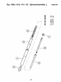
1086 1430
September 1995
Warning
This equipment must be installed and
used in accordance with the
manufacturer's recommendations.
Installation must be performed by
properly trained and authorised
personnel.
Failure to follow these instructions may
invalidate your warranty and/or impair
the safe functioning of your equipment.
Please contact your local Wallac
representative for installation.
WALLAC
1414-932-02
March 1996
INSTRUMENT MANUAL
1414 WinSpectral
TM
Digital Spectrum Analysis (DSA) based liquid
scintillation counter
For instruments with software version 1.3
including WinSpectral aJfi and Guardian
WAIIAC
AN
^EGzG
COMPANY
Wallac Oy, P.O. Box 10, FIN-20101 Turku, Finland. Tel: +358-21-2678111 Telex 62333 wac fin, Telefax: +358- 21-2678 357
Contents
Contents
1 Introduction
Introduction
Hardware features and benefits
Software features and benefits
l-l
I-2
I-7
2 User manual
3 Calculation methods
4 Quality control information
Warning regarding installation and warranty
QC contents
5 Installation information
Installation
MultiCalc installation
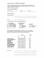
Installation report for Wallac 1414 WinSpectral
Installation report appendix
5-1
5-7
6 Specifications, Safety and Routine maintenance
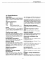
6.1 Specifications
6.2 Safety and radioactive materials
6.3 Routine maintenance
7 Spare parts information
8 Index
6-1
6-3
6-5
Trademarks
WinSpectral, FlexiRack, DOT-DPM, Poslden, ChemiStrip and MultiCalc are trademarks of Wallac Oy
Lotus 123 and Symphony are registered trademarks of Lotus Development Corporation
MS-DOS, Microsoft, Windows and Excel are registered trademarks of Microsoft Corporation
Pentium is a registered trademark of Intel Corporation
1 Introduction
Introduction
Introduction
A new LS counter
The Wallac 1414 range of DSA liquid scintillation
counters, WinSpectral, WinSpectral oc/f$ and Guardian,
is created to bring the very latest in LSC and PC technology to your laboratory. The combination of Digital
Spectrum Analysis (DSA) with the Microsoft Windows graphical user interface as well a/p separation
(WinSpectral a/|3 and Guardian) and sophisticated
shielding (Guardian) makes an unbeatable combination.
PC display for
I WinSpectral
software and
live results
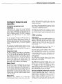
In this manual you will find a description of what you
can do with your counter (whichever model you have),
including the various options available, an explanation
of how to use the instrument, as well as background
information about how it works and how to install it.
Note: in this manual the name WinSpectral is normally
used and no distinction is made between the three different models except where they differ.
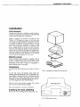
The figure below shows the instrument and identifies
the different parts of the system.
Instrument on/off
switch and sockets
for cables to PC and
raw data printer
Instrument cover.
(Keep closed
when counting)
Output
printer
PC
keyboard
Disk drive for program
disk (behind cover)
Wallac 1414 WinSpectral and peripherals
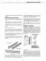
Hardware features and benefits
The sample conveyor has two lanes for sample racks,
an in-stream (on the right) and an out-stream, as well
as two transfer lanes, one of which is the counting
lane. Sample racks glide along the in-stream and outstream of the conveyor, moved by friction contact with
two rubber belts. Movement along the transfer lanes is
by precision made toothed belts. The conveyor is
coated by an electrically conductive teflon layer to reduce friction to a minimum and to prevent the generation of static electricity on the sample racks. The conveyor motors run very quietly to avoid disturbance to
users and others in the laboratory.
Hardware features and
benefits
Elegance
The first things that comes to your attention when you
look at a Wallac 1414 WinSpectral DSA liquid scintillation counter are the elegant lines of the conveyor
cover and the conveniently placed PC screen, keyboard and mouse. These impressions of elegance and
convenience are not just superficial features of the
counter, they run through every aspect of the WinSpectral hardware and software. These features and
the benefits they bring you are described in the following chapters.
All movement is controlled by stepper motors and directly triggered optical sensors. This removes the danger of sensors jamming and increases the reliability of
the whole conveyor system. Sample change time is
about 9 sees.
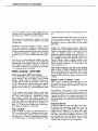
FlexiRack™ sample changer
The conveyor is designed to give the maximum visibility to the user. You can easily see the sample racks
wherever they happen to be on the conveyor. The
cover of the conveyor is made of a plastic which both
allows a clear view of the conveyor yet shields the
samples from ultra-violet light and thus reduces the
problem of chemiluminescence. The cover is supported by a spring-loaded lever so that it opens and
closes smoothly.
Conveyor movement is fully bi-directional. With the
OneRack function counting is interrupted, the rack in
the counting position is driven backwards so that you
can load a single rack for stat counting. After this rack
has been counted, counting of the other racks resumes
automatically. You do not have to remember to put the
interrupted rack back at the head of the in-stream later
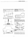
Coloured
dot
Disk drive
cover
Empty
stop
rack
Loading racks on Wallac WinSpectral
1-2
Hardware features and benefits
on because it is already in the right position to resume
counting.
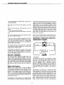
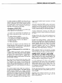
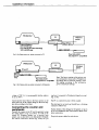
Multi-size racks and vials
You are no longer limited to using only one size of
rack on the conveyor if you have the appropriate options:
With FlexiRack I you can load racks of twelve 20 ml
samples along with racks of eighteen 6 ml samples.
With FlexiRack II you can not only load racks of the
above two types but also racks of twenty-four 4 ml
samples.
These can be in any order.
A 20 ml sample rack can hold twelve samples with a
maximum vial diameter of 28.4 mm. The conveyor
will accept 28 racks making a full load of 336 samples.
The corresponding figures for 6 ml vials are 18.4 mm
diameter, 18 samples per rack and 40 racks on the
conveyor making 720 samples in all.
vial of the maximum diameter in any of the categories
its length can be up to 68 mm. Smaller vials in any
category can be a few millimetres longer.
Not only flat bottomed vials can be accepted but also
round bottomed and conical vials. For example adapters allow Eppendorf tubes and Microfuge tubes to be
counted directly without the need for carrier vials.
Users with different vial sizes can load their own
batches of samples on the same conveyor at the same
time.
Poslden™ ID reader
The purpose of the ID system is to allow 'hands off
performance of the instrument and to enable total results identification. 'Hands off means that counting
procedures such as changes of protocol, quench fine
tuning or stat counting, can be initiated automatically.
Good laboratory practice requires that the results are
identified in data files or on printouts with ID numbers. The Wallac WinSpectral Poslden ID reader enables all this.
PROTOCOL NO.
For 4 ml vials the figures are 13.4 mm diameter, 24
samples per rack, 52 racks per conveyor load, i.e. 1248
samples.
6 ml sample rack
Rack number or
standardization or
INTERRUPT RACK
Poslden system
20 ml sample rack
Racks for different vial sizes accepted by the FlexiRack system
The maximum height allowed for the top of a vial
above the conveyor is 78 mm. This means that for a
Poslden uses a barcode reader and ID labels. These are
self-adhesive and attach to a strip of plastic, the ID
Clip which is then attached to the end of the sample
rack. The position of the clip is such that the coding
can be easily read without moving the rack, wherever
the rack is on the conveyor. The combination of ID
labels and clips allow each laboratory to prepare the
Hardware features and benefits
The clip for the first rack in the assay has up to two
labels
- a label with the protocol number.
- an optional label with the rack number for the first
rack.
and by the fact that at no point does the vial come into
contact with any material which might tend to deposit
charge on it since a vial in the FlexiRack™ system is
raised directly into the measuring chamber without
making further contact with other materials. The rack
design also reduces static charge build-up, because the
samples are located in round holes in the rack without
any sharp edges which tend to collect static charges
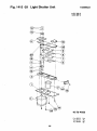
more easily. The light shutter is in the form of two
plates which close around the stem of the elevator after the vial is in position.
The clips for other racks in the assay need only to have
the rack No. label fixed them
There is also a Statistic Monitor which flags any samples which show signs of static electricity discharges.
If the rack contains quenched standards the ID Clip is
coded with a label showing the quench protocol number (1-99) and instead of rack No. a special label
which identifies the samples in the rack as samples for
spectrum library fine tuning.
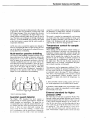
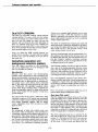
Automatic continuous spectrum
stabilization (ACSS)
needed combination of coded ID Clips to meet its individual requirements.
The ready-to-use ID Clip can have labels on it as follows:
w
LED
A
PMT
For automatic interrupt counting the rack is coded with
a clip with the protocol number and a special label
indicating the interrupt function.
The ID labels are supplied in a binder with 20 sheets
of labels. The ID Clips are supplied in a package of
100. The box on the PC keyboard shelf can be used to
share the ID binder and clips.
PMT
Calibration pulse
Sample spectrum
Elevator reliability
The elevator system is designed to handle a whole variety of sample vials without the danger of the vials
falling over or getting jammed. The key to this is the
small sized elevator head combined with the centralizing counterweight. The counterweight meets samples
before they are raised from the rack thus ensuring that
they remain vertical all the time they are on the elevator.
ACSS system
You need to be sure that your instrument is stable.
You do not want changes in high voltage, temperature,
detectors or aging to affect the accuracy of your results. The patented built-in "automatic continuous
spectrum stabilization" system ACSS offers gain stability for your Wallac WinSpectral counter without the
need to measure reference samples. This system is
completely automatic and requires no user intervention.
Static elimination
Plastic vials are widely used in liquid scintillation
counting and manufacturers tend to use plastic also as
a rack material. Conditions are often optimum for the
build-up of static charge, especially when relative humidity is low (central heating) and lab technicians
have to use plastic gloves during sample preparation
(as when using conventional toluene, xylene and cumene based cocktails).
The principle is to detect when a change that would
affect the gain of the instrument occurs and by means
of a feedback loop to correct for the change so that the
gain remains stable. Each photomultiplier has a temperature compensated reference light emitting diode
(LED) which is fixed close to each detector and is
used to check the gain of the PMT, see the figure
above. A reference pulse is produced in the photomultiplier 10 times a second. The ratio of the pulse pro-
Static build-up on the sample vials is minimized both
by the presence of ionizers around the sample elevator
1-4
Hardware features and benefits
duced at the first dynode to that produced at the anode
is measured. This ratio should be constant even if the
LED output changes. If the ratio changes then the gain
has changed. To compensate, the high voltage is adjusted until the reference pulse ratio is back to what it
was. This takes care of changes to the high voltage and
detectors. A second feedback loop monitors the signal
at the first dynode to ensure that the whole system is
temperature stabilized.
ACSS also acts as a protection against any damage to
detectors through light leaks. If a leak occurs, the voltage to the detectors is automatically reduced thus protecting them from overloading.
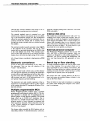
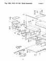
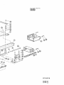
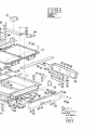
Multi-section passive shielding
The massive lead shielding combined with the coincidence electronics for the pairs of detectors reduces the
background to a low level. However this shielding
does not make for an instrument too heavy to be conveniently handled because you can easily remove the
lead shielding and then reassemble it when the instrument has been moved to its new position. The figure
below shows the pieces and the order in which they
should be removed from WinSpectral. Assembly is
performed in the opposite order. See the installation
chapter for more information about shielding.
caused by a particle or photon from the environment.
No limitation in sample fluor selection is introduced
by this background subtraction method.
The guard is switched on automatically, and remains
on except when the external standard is being used.
Usage of Wallac Guardian is thus identical to that of
Wallac 1414 WinSpectral oc/p\ but the performance is
improved due to the lower background rate.
Temperature control for sample
homogeneity
When dealing with the maximum sample holding capacity of scintillators it becomes very essential that the
temperature remains practically constant through the
whole sample batch. Proper temperature control guarantees that all samples are counted at the same temperature in spite of variation of ambient conditions (if
for instance the air conditioning is turned off during
the night time). Thus the risk of phase separation in
samples due to, for example, a temperature drop during overnight counting, is eliminated.
The conveyor can be temperature stabilized. This is
achieved by installing the optional Temperature Control unit which can be set to maintain the temperature
at a selected value in the range 5°C below ambient to
10°C above. The temperature control system is based
on two thermoelectric (Peltier) modules, which enables users to adjust and control the temperature via
software.
A more powerful external cooling system (10° C below room temperature) can be added later if needed.
A parameter called TEMP in the programmable output
allows you to output the temperature at which sample
measurements were made.
Order for removing shielding
Guardian guard detector
The Wallac 1414 Guardian low level counter is
equipped with an external guard detector around the
sample chamber and phototubes. The guard has its
own phototubes and is optically isolated from the sample chamber and thus offers true background event detection. It does not cause observable counting efficiency losses in low level counting. A sample event
that is simultaneous with the guard event is rejected by
the electronics since the event is then most probably
External standard for higher
precision DPM
The wide range of vial types accepted by Wallac WinSpectral counters puts greater demands on the external
standard parameters than ever before. If the count rate
of the external standard depends on the sample volume, the few microlitres in a Microfuge tube will give
a iow count rate. To avoid this the isotope of the external standard is '' Eu, which belongs to a lower toxicity class than previously used external standard isotopes, which means a higher activity can be used thus
Hardware features and benefits
allowing the external standard count time to be reduced and the counting precision increased.
spectrum stripping background correction and DOT
DPM calculation.
Internal disk drive
The external standard source is mounted on a wire
which moves it from its rest position in its own shielding to just beneath the sample vial. This arrangement
allows the external standard to be positioned very accurately beneath the sample vial (it actually moves
through the sample elevator shaft to a position beneath
the sample).
The counter has an internal disk drive with a 3.5" microfloppy disk which contains the program. The program disk can easily be changed to accommodate program changes and updates. This is a much simpler procedure than changing chips on an electronic circuit
board. This drive is behind the cover at the front of the
conveyor as shown on page 1. To access the drive you
must slide the cover upwards to release it.
The external standard quench parameter value SQP(E)
is the endpoint of the spectrum. The use of " Eu
means that you get high precision for the SQP(E) due
to the well defined end of the ' Eu Compton spectrum and also high sensitivity for the colour correction
feature due to the relatively high energy of the isotope.
External personal computer
The WinSpectral Windows software runs on any 386
(SX), 486 (SX) or PENTIUM computer. Since our
counters are designed to work within standard PC architecture, you can be assured that WinSpectral will
serve you long beyond the 486 generation of computer.
All of these features contribute to high precision DPM
results.
Electronic convenience
Bench top or floor standing
So far we have been concentrating on the "body" of
the instrument. Now we turn our attention to the
"brains" - the electronics.
A Wallac WinSpectral DSA LSC can be either bench
top or floor standing. You can select which ever is
most convenient for your working environment. The
Wallac Floor Stand allows the counter to become floor
standing and easily movable without having to collect
together lots of separate pieces of equipment.
This is basically found in three racks and the detector
unit. The proven approach of mounting the electronics
in racks allows easy upgrading and service thus reducing down time when any changes are made. The central processor unit uses a 16 bit microprocessor to ensure speedy response and data handling.
The monitor arm and a pullout shelf for the PC keyboard and mouse are standard features whether or not
you use the Floor Stand.
These all make for ease and convenience in operating
the system while keeping the footprint in the laboratory to a minimum.
The electronics not only controls operation of the instrument but it communicates with PC to allow control
of the counter from the PC running the Windows WinSpectral software.
Multiple programmable MCA
Wallac WinSpectral DSA counters have a multiple
programmable multichannel analyser (MCA). The isotope spectrum is divided into 8 logarithmically set
spectral ranges of 4096 discrete channels. The tritium
range offers up to 0.0038 keV resolution, this is
equivalent to a 520,000 channel linear MCA. The appropriate number of linear channels are summed into
1024 logarithmic channels. These retain the precision
of the original analogue to digital conversion of
0.0038 keV per channel.
This feature makes possible the DSA features such as
ChemiStrip method of chemiluminescence correction,
1-6
Software features and benefits
quate in older generation counters since minor temperature fluctuations or voltage changes can affect the
response at any time.
Software features and
benefits
The basis for Wallac WinSpectral's superior performance is Wallac's patented ACSS feature (see the previous chapter on Hardware features).
Windows graphical user
interface
Older types of LSC software still run under MS-DOS
a character based operating system. Since MS-DOS
does not allow the possibility of multitasking, any application program or commercial software must be run
after the counting protocols. This kind of sequential
operation inhibits the effectivity of a busy research
team.
The GLP protocol allows you to quickly set parameters for the monitoring of up to 8 performance parameters for GLP and get a ready formatted report after the
run.
CPM counting
Introduction
The new generation WinSpectral software running under Microsoft Windows offers dozens of features. No
longer are you limited to 640 kB of memory or character based software packages. You can exchange data
between WinSpectral and any Windows compatible
software.
CPM counting is used when sample preparation is expected to yield samples with close to constant counting
efficiency. This means that the results of the samples
in an assay can be compared with each other and used
in further data analysis. A typical CPM application is
filter counting.
The graphical user interface itself is intuitive and easy
to use. Operation involves clicking buttons or icons
with a mouse pointer or selecting items from menus on
the PC screen.
Wallac WinSpectral allows you to select from six
common isotopes plus an additional 69 others.
One error source in CPM counting is that of unexpected counting efficiency variations, e.g. partial elution of the sample from the filter disk. Your Wallac
counter includes features to detect and inform the user
of counting efficiency variations as described below.
Hypertext help
All steps of operation are guided by comprehensive
context sensitive help screens conforming to the style
you are used to with other Windows software packages. Simply press the Fl key to get help for just the
point of operation you are at. You can use the help to
search for information on any feature you like. The
hypertext links enable you to instantly jump in the
help to other related pieces of information. The hypertext help is truly a manual at your fingertips
CPM monitor
The CPM Monitor is another feature of your counter.
It allows you to be confident of the consistency of the
quench level of your samples.
The CPM Monitor checks the SQP(I) value of each
sample. If this is within 10% of SQP(I) the first sample then there is no flag. If the difference is larger it
then calculates and outputs the percentage ratio of the
sample SQP(I) to the first sample SQP(I). The acceptance limit (default 10%) is a system parameter and
can be changed there, see the User manual.
Easy Count
If you do not want to set parameters then you can use
the Easy Count feature. You simply load the samples
and click the Easy Count button. The DSA feature allows the counter to determine automatically which isotope you are using from a selection of three (~ H or C
are the defaults) and then counts the samples. An Easy
Count protocol can also be initiated by using a special
ID label on the racks. Easy Count is described in detail
in the User manual.
Spectrum stripping background correction
The traditional methods for background correction are:
a typed in background CPM value or a CPM value
measured from a background sample in a counting
window. However the intensity of the background radiation is different at different energy levels so these
methods do not give the best result. The new calculation methods in Wallac WinSpectral DSA counters do
Easy GLP
Compulsory daily calibration, the so-called GLP
(Good Laboratory Practice) feature has proved inade-
1-7
Software features and benefits
not utilize counting windows, but use digital spectrum
analysis (DSA) to calculate the CPM/DPM values over
the MCA area covered by the sample spectrum.
ing), methods based on factory installed quench curves
etc.
Common to these methods is that they are not universal, this means they are good for some applications but
give bad results for others. This requires a good
knowledge to select the right method for any specific
application.
The background counting time is selected to be either
the the same as or five times the length of the sample
counting time.
Background correction proceeds as follows. Firstly,
one or more background samples are measured and a
background spectrum accumulated. Then using the
spectrum stripping technique the background spectrum
is subtracted channel by channel from the sample
spectrum. This gives you a reliable background correction.
Usually the methods require special calibrations,
quench curves, to be measured which are dedicated to
a specific experimental situation, isotope pair, cocktail,
colour or chemical quench etc. Preparation of
quenched standards, checking of quench curves etc. is
time consuming. In dual label counting, counting window settings are critical and different isotope ratios
demand different window settings. Separate standardizations must be done for different isotope combinations. Possible occurrence of colour quench will
cause systematic errors.
Note: If you use both background samples and reference samples then the positions of the background
samples must be immediately before those of the reference samples and start from position 1. If there are
only reference samples they must begin from position
1. No empty positions are allowed.
The Wallac solution, one universal method
DPM counting in Wallac WinSpectral uses the DSA
features, the Digital Overlay Technique, DOT, and the
use of spectrum libraries. DOT is the most general
method available today for quench correction in LS
counting.
DPM counting - DOT DPM
Why the need for DPM correction?
A fact which makes LS counting unique among analytical methods is that each sample is also a unique
detector. Usually analytical methods are based on the
principle that the sample emits radiation or some form
which is measured in an external detector, e.g. gamma
counter or an external, source sends radiation which is
absorbed by the sample, e.g. spectrophotometric methods.
Digital Overlay Technique - DOT
DOT is used to reconstruct a standard spectrum at the
same quench level and intensity as the unknown sample. When the standard spectrum has been fitted, the
DPMs are calculated.
The procedure is the same for dual or triple label
counting except that when the standard spectrum for
each isotope has been reconstructed these spectra are
combined and fitted to the composite spectrum of the
unknown sample. After a successful fit the isotope ratios and intensities are established and the DPM values
calculated.
In LS counting, each sample consists of the actual
sample mixed with the detector, the scintillation cocktail. Thus counting efficiency is dependent on sample
type, sample to cocktail ratio, volume, colour of the
sample, cocktail type etc. The counting efficiency variation from sample to sample must be corrected for to
allow comparisons and analysis of the samples in a
batch. To do this several methods have been developed during the lifetime of LS counting.
Spectrum library
A Wallac WinSpectral with DOT DPM has a library
of spectrum data comprising information about isotope/cocktail/vial type combinations for about 100
quench levels (10 chemical x 10 colour). This library
is built-in to the counter during its production. Along
with each combination the SQP(E) and colour index
are determined and saved. WinSpectral then works not
with quench curves, but with quench surfaces which
represent both chemical and colour quenching.
Other methods
Several methods are offered for DPM calculations in
LSCs e.g. methods based on counting windows, methods based on isotope spectrum quench parameters,
methods based on external standard quench parameters, methods based on extrapolation (Efficiency Trac-
1-8
Software features and benefits
In sample counting, the SQP(E) and colour index are
measured and the corresponding point on the quench
surface is determined. This is then combined with the
the counting mode, isotope and vial type specified in
parameter setting to get a specification for the spectrum data to be selected from the library.
Advantages of DOT DPM
- the Wallac library provides Easy Count DPM results
without quench curve measurements.
in the external standard quench parameter and bigger
DPM errors.
In the DOT method the SQP(E) value is only the starting point for an iterative procedure which searches the
spectrum library for the spectrum which gives the best
possible fit to the measured unknown spectrum. The
Accuracy Enhancement gives the following features:
Accuracy Enhancement minimizes the DPM errors
caused by erroneous external standard quench parameter values.
- no quench curve measurements are needed for specific isotope combinations in dual or triple label counting.
- no window settings are needed
- result quality is not dependant on isotope ratios
- a successful fit gives assurance of sample quality
- no systematic errors caused by colour quench
- no plastic vial effect
- no volume dependence
Savings in time, only a few seconds counting time is
needed for the external standard even for samples with
small volumes.
Normally the counting efficiency - quench parameter
relation is also dependent on the quenching agent and
the cocktail used. Thus if the samples are quenched by
another quencher than the one used for the quench
curve systematic errors will occur. With Accuracy Enhancement systematic errors due to 'Quenching
agents' or different cocktails are minimized, thus the
applicability of the Wallac libraries is increased.
DOT allows for analysis of the fine structure in the
isotope spectrum which can be used to warn the user
of phase separation, contaminations or other phenomena which will give erroneous values.
Accuracy Enhancement for even better results
When using Easy Count it is not necessary to specify
spectrum library or vial type, Accuracy Enhancement
will search through all variations to find the best fit.
A typical DPM measurement includes determination
of quench level with the help of the external standard,
calculation of the counting efficiency corresponding to
the quench level with the help of a quench curve,
counting of the sample to obtain sample CPM and then
the final DPM calculation.
SQP(I) DOT, Single Label DPM
The SQP(I) DOT option offers you single label DPM
results without the use of the external standard. The
method is based on the Digital Overlay Technique.
This means that no counting window is required.
The critical factor which determine the quality of the
DPM results is how correctly the counting efficiency
was determined. The accuracy of the counting efficiency value is totally depending on how accurate the
External Standard Quench parameter is and how exactly the quench curve used represented the unknown
samples.
To use the SQP(I) DOT you need to make a quench
standardization or fine tuning of one of the HiSafe or
Xylene quench data sets in the Wallac library. The
standard spectra and the counting efficiency are stored
as a function of the SQP(I) instead of the external
standard quench parameter.
The external standard values suffer from counting error due to the counting statistics. The modern external
standard quench parameters are usually calculated
from the endpoint of the external standard spectrum
and depend on the shape of the spectrum. With higher
quench levels and smaller sample volumes the shape
becomes more and more undefined and the counting
error greater. Consequently there will be bigger errors
The fine tuned spectrum library can then be combined
with counting protocols to obtain DPM results of unknown samples.
Depending on the number of protocols (15 or 100) the
SQP(I) DOT option allows you to make 14 or 99
quench standardizations.
1-9
Software features and benefits
allows you to measure alpha radiation with a background of less than 1 CPM. The sensitivity for alpha
detection approaches the detection limit for semiconductor alpha particle detectors but with considerably
simpler sample preparation.
Dual DOT CPM/DPM
This offers you dual label counting without using the
external standard. You need to make two fine tunings,
one for each isotope to be used to label unknown samples. For each fine tuning you must only use one
standard and the chemical and colour quenching of
these two standards must be the same. Samples can
have quench levels which differ to some extent from
those of the standards because the Accuracy Enhancement procedure takes account of this.
The ability to simultaneously measure gross alpha and
gross beta activity reduces the workload in the laboratory because the alpha detection level is sufficient to
detect alpha activity at the picocurie activity levels
which are the allowed activity limits.
When you define the DPM counting protocol you
specify the two isotopes to be used, then the program
prompts you to give the numbers of the two sets of
fine tuned data.
Moreover simultaneously with the measurement of alpha radiation, beta radiation from the decay chain can
be detected and analyzed. The beta spectrum may contain also Cerenkov radiation, conversion electrons,
Compton electrons, X-rays and Auger electrons if they
are being produced in the sample.
Alpha/beta separation and
background reduction (option)
Note: this feature is an option for 1414 WinSpectral
and can be installed later; for 1414 WinSpectral oc/p
and 1414 Guardian it is built-in.
The PSA/PAC features can also be used to discriminate a part of the background pulses from the sample
pulses. The best benefit of this is obtained when glass
vials and a fast scintillator are used. Especially in low
energy beta counting considerable reduction of glass
vial background can be achieved by using the PSA.
Introduction
Electrons from beta decays and electromagnetic
(gamma, X-ray) interactions as well as Cerenkov phenomena produce pulses consisting mainly of prompt or
fast fluorescence. On the other hand, the heavily ionizing particles, such as alpha particles or neutrons produce pulses with a more delayed (slow) component
and are thus longer than those produced by beta particles. WinSpectral with alpha/beta separation option
utilizes Pulse Shape Analysis, PSA, to separate between the long pulses typical for alpha decay and the
shorter pulses typical for the gamma or beta background radiation.
The other function of this option is called PAC (pulse
amplitude comparison). PAC rejects more background
counts than sample counts because background pulses
have greater amplitude disparity than do sample
counts. Adjustment of the PAC can lead to a better
figure of merit.
Benefits
The background of glass vials exhibits some slow
fluorescence which is induced by cosmic and other environmental radiation and the inherent radioactivity of
glass material. Pulse shape analysis is therefore a useful method of reducing this background in beta counting. The glass fluorescence appears mainly in the spectrum region of low energy beta particles such as those
from tritium. The simultaneous alpha/beta separation
Due to this alpha/beta separation feature Wallac WinSpectral with this option has a lower background than
a standard LS counter. Thus the improved sensitivity
can be used to minimized sample volumes and specific
activity, with savings in consumables and waste as a
result.
Note: vial carriers as an guard for small vials can be
used to further improve background values.
How does PSA work?
The PSA integrates the delayed (tail) and the prompt
(peak) light pulse from a sample producing both types
of radiation. If the ratio of the delayed to prompt component exceeds the preset ratio, the pulse is directed
into the long pulse or alpha spectrum. If the ratio does
not exceed the preset ratio the pulse is directed into the
short pulse or beta spectrum. Very low background
count rates are achieved for alpha particles, since most
of the LS background is composed of short pulses.
The above mentioned preset ratio is controlled by the
user with the PSA level, whose range is from 0 to 255
in steps of 1. The higher the PSA level is set, the more
counts will be directed into the long pulse spectrum.
At PSA level = 255 all counts are directed into the
1-10
Software features and benefits
long pulse spectrum, and at 0 all counts go into the
short pulse spectrum. An optimum value for the best
alpha/beta separation can be found somewhere between these two extremes as explained in the next
paragraph. PSA levels higher than the optimum reduce
beta counting efficiency and and background leading
often to better figures merit. Lower PSA levels than
optimum do same for alpha counts.
Determining the PSA level
Cocktails produce different pulse lengths; HiSafe
cocktails show relatively slow pulses while xylene and
toluene based cocktails are fast. The PSA option allows the optimum PSA level to be found to match the
cocktail speed. This is done by stepping over a range
of PSA values.
Ascertaining the correct PSA level is ideally done with
two reference samples: one that emits alphas (e.g. Am241) and the other that emits betas in the alpha spectrum range (e.g. Cl-36, Sr-9O, P-32). Count rates
should be kept below a reasonable limit by dilution if
necessary (less than 10 000 CPM is recommended).
The reference samples must be made in the same type
of vial, same cocktail and same mixing ratio as the
actual unknown samples to be measured.
A protocol can be created which steps PSA levels over
a range which is appropriate for the cocktail. See the
User manual for details. There are two extra windows
that can be set which in range are typical for the alpha
region but the first one is for measuring the beta spectrum (short pulses) while the second one is for the
alpha spectrum (long pulses). The results are printed,
each line contains the CPM value for both windows,
the PSA level used and a calculated field, 'RATIO'
which is the CPM value in the alpha window divided
by the total CPM value. For example, you can select
the final PSA level to allow from 0.5 to 5 % loss of
alpha counting efficiency (alphas spilling into the beta
channel). In this way an almost pure alpha spectrum is
acquired with the minimum loss of counting efficiency. In the same way, when you are only interested
in beta counting in the presence of alphas (or glass
originated background) you may allow some percentage loss of beta counting efficiency, (betas spilling
into the alpha channel).
Note that the slower the cocktail the lower will be the
optimum PSA level. One may use a more limited window to include the main alpha emission range, e.g. for
3-11
Ra-226 and Rn-222 Ch 600-800 is good with water
miscible HiSafe cocktails.
A printout and a plot of 'RATIO' vs. repeat number is
generated in the run and the spectra are saved.
The optimum PSA level for glass vial background reduction in beta counting is found in a similar way.
You prepare two samples, one "hot" and one background sample. You then step over the desired PSA
levels and select the final level with e.g. 10 % of "hot"
counts spilling into the alpha category.
For rapid use without stepping you can select LOW as
the default PSA level for slow cocktails and HIGH for
fast cocktails.
How does PAC work?
The Pulse Amplitude Comparator (PAC), can be used
for background reduction in uncoloured samples. The
sample pulse amplitudes from the left and right phototubes differ less from each other than do the background pulse amplitudes since quite many of the latter
ones are generated in the phototubes themselves by
environmental and internal radiation.
Determining the PAC level
To find the suitable PAC level for optimum background reduction an active beta sample and a blank
sample are made, matching the samples to be measured in the type of cocktail, mixing ratio and vial.
A protocol can be created which scans the PAC levels
over a range which is appropriate for the cocktail, see
the User manual for more details. Both the active sample and the background are measured. The count rates
in the windows of the beta emitter are printed.
There are two extra windows, both wider than the
whole spectrum but the first one is for the beta spectrum while the second one is for the PAC rejected beta
spectrum. The results are printed, each line contains
the CPM value in each window, the PAC level used
and a calculated field, 'RATIO' which is the CPM
value in the beta window (the pulses with less amplitude disparity than defined by the PAC level) divided
by the total CPM value. The higher the PAC level the
closer to each other must the amplitudes be for the
pulse pair to be accepted. A greater number of pulses
will be rejected at high PAC values than at low ones.
Software features and benefits
A printout and a plot of 'RATIO' vs. repeat number is
generated in the run and spectra saved.
The optimum PAC level is the one at which E*E/B,
beta counting efficiency squared over background or
figure of merit in the beta window, is at a maximum.
PAC does not reject alpha pulses as much as beta
pulses since the number of photons from an alpha decay is very much greater than that from a beta decay.
The variation of the left and right pulse amplitudes is
thus less for an alpha decay event than for a beta decay.
Chemiluminescence
Why is chemiluminescence a problem?
About two thirds of all samples in LSC are of biological origin which means that they comprise long macromolecules. In order to get them soluble in organic
scintillator solution these macromolecules have to be
hydrolysed to smaller fragments. This process often
results in the release of chemiluminescence in samples.
How is it solved?
There are two levels of solution to the chemiluminescence problem, the first of which is common to most
beta counters and the other is specific for Wallac WinSpectral DSA counters.
Chemiluminescence events are "single photon" ones.
Each time chemiluminescence occurs a single photon
is emitted in one direction. In contrast, a normal radioactive decay releases a burst of several photons in different directions (a "multiple photon" event). A beta
counter has two detectors viewing the sample vial
from opposite sides. A chemiluminescence event (or
any other single photon background event or random
noise event in a detector) will trigger only one of the
detectors whereas a radioactive decay will trigger both
detectors almost simultaneously. By requiring that a
signal be received from both detectors within a few
nanoseconds and by rejecting signals that only come
from one detector or the other, most of the chemiluminescence and random background can be cut out.
However there are limits. The period of a few
nanoseconds referred to above is called the coincidence resolving time of the detectors. If two chemiluminescence or other random events occur within the
coincidence resolving and so that each triggers one of
the detectors then the result will look like a true multiple photon event and will be counted. If there is a high
rate of chemiluminescence events many of these "random coincidences" will occur resulting in false count
results. The DSA feature ChemiStrip™, a unique patented spectrum stripping chemiluminescence correction method, solves this problem.
The counter has five 1024 channel MCAs. ChemiStrip
uses one MCA to store the combined sample and
chemiluminescence spectrum and another the chemiluminescence alone. This second spectrum is obtained
by making use of the difference between the chemiluminescence and sample spectra. The latter comes from
discrete bursts of photons which occur within the coincidence resolving time of the detectors. If the signal
from one detector is delayed relative to the other then
no coincidence will occur and no count will be recorded in the "delayed spectrum" MCA. In the case of
chemiluminescence the spectrum is formed by an almost continuous flood of photons. This means that
there is just as much chance of a random coincidence
between two single photon events occurring at the
same time as there is between one event and the delayed signal of a previous event. The chemiluminescence events will thus contribute to the delayed spectrum whereas the sample events will not.
Channel by channel stripping (subtraction) of chemiluminescence from the sample + chemiluminescence
spectrum is then done. This maintains the exact shape
of the sample spectrum by removing the exact chemiluminescence spectrum from the combined one. The
corrected CPMs are then used in further calculations.
The result is that you can cease to worry about chemiluminescence. Just select chemiluminescence correction "on" and and your Wallac WinSpectral will look
after the rest.
Isotope decay
The problem of decay
If you are counting samples labelled with an isotope
such as phosphorus 32 with a half life of 14.2 days
you are likely to face the situation where the count rate
for samples drops over the course of an assay. In this
case there will be about a 1% change from the first to
the last samples in three hours. With longer counting
runs or repeat runs over several days this could introduce significant errors in your results.
1-12
Software features and benefits
The solution
Sample Quality Monitor
When you are setting your LSC or measurement parameters protocol you select half-life correction as part
of the advanced mode parameter. Since you will have
already specified the isotope(s) used the counter will
know exactly what correction to make. In addition,
you can specify if you want the initial time for the
correction to be the start of the counting of the assay
or a date which you set. See the User manual for details of parameter setting.
Wallac WinSpectral DSA counters include a Sample
Quality Monitor which can be chosen in output selection (see Output items in the User manual).
Sample quality monitor
Sample inhomogeneity
One problem in liquid scintillation counting is inhomogeneity of the mixture composed of the sample being analysed and the liquid scintillation cocktail. If
sample and cocktail are not adequately mixed some of
the beta particles will be absorbed in the sample phase
and thus not reach the scintillation liquid phase. This
will appear as a reduced counting efficiency for the
sample.
This happens because the external standard spectrum
which is produced by the Compton electrons resulting
from the gamma radiation from the external standard,
is not affected by the inhomogeneity of the sample and
cocktail mixture. This is because the Compton electrons are generated throughout the whole volume and
thus will produce scintillations effectively. The counting efficiency might even be improved for the external
standard as the quenching agents are in the sample
phase.
Thus the counting efficiency obtained from the measurement of the external standard is not correct if the
sample and cocktail mixture is two phased.
The sample and liquid scintillator mixture can be homogeneous when the counting starts, but as time goes
the last samples can be inhomogeneous if the samples
are close to the sample holding capacity of the cocktail. When using an emulsifying cocktail, the sample is
suspended in "drops", micelles, in the cocktail. The
micelles are small compared to the range of the beta
particle energy so that absorption in the micelles is
minimized. However if the sample amount is big close
to the sample holding capacity the micelle start to
grow which will affect the counting efficiency.
1-13
In the DPM case this monitor evaluates the amount the
spectrum of the external standard and the unknown
samples deviate from the library values you are using.
If the deviation is not significant then the monitor
gives the output "100".
If there is a significant deviation but one that might be
accounted for by some fine tuning of the library then
the sample quality monitor is below 95. You should
check your sample and if it seems all right you should
consider fine tuning the library you are using.
The Sample Quality Monitor warns you of problems
with your sample as well as indicating when fine tuning is necessary.
Sample count rate variation
monitor (Statistics Monitor)
The problem
Plastic vials are widely used in liquid scintillation
counting and manufacturers tend to use plastic also as
a rack material. Conditions are often conducive for the
build-up of static charge, especially when relative humidity is low (central heating) and lab technicians
have to use plastic gloves during sample preparation
(as when using conventional toluene, xylene and cumene based cocktails).
The solution
Wallac WinSpectral has a built-in ionizer unit which
removes static charges by sending positive and negative ions towards the vial. Since the vials in the FlexiRack™ system are raised directly into the measuring
chamber without making further contact with other
materials, the ionizer is very effective. The rack design
also reduces static charge build-up, because the samples are located in round holes in the rack without any
sharp edges which tend to collect static charges more
easily.
In addition to the ionizer there is the Statistics Monitor. The purpose of this monitor is to warn of unacceptable count rate variation in a sample. The sample
count rate in different periods of the sample counting
time is measured to determine the sample count rate
variation. A % test is used to see if the count rate
Software features and benefits
variation for each sample lies within the range expected from the statistical nature of radioactive decay.
Sometimes it may not lie within this range due to, for
example, chemiluminescence, radio frequency signals,
static or extreme cases of normal statistical variation.
In such cases of unexpectedly high sample count rate
variation the sample is recounted.
Other computer interfaces
Wallac WinSpectral can also save data in ASCII format files or binary WKS type files. The WKS type
files can be read directly into spread sheet programs
such as LOTUS 123, Symphony or EXCEL.
Spectrum analysis (option)
Note: this feature is an option for 1414 WinSpectral
and can be installed later; for 1414 WinSpectral a/p
and 1414 Guardian it is built-in.
The test is applied to both the sample alone and the
sample with the external standard in position. A maximum of two recounts are made for each of these cases.
The various flags that can appear are given in Output
items in the User manual.
Alpha counting and low level beta counting applications include spectrum analysis as a final step.
After a second recount (if there is one) the result of the
second recount will be appear as output then counting
of the next sample or repeat will begin.
The counter saves the measured sample spectra in the
connected PC. The spectra can then be analyzed off
line using the Wallac Spectrum Analysis program.
The chemiluminescence monitor and correction feature as well as the special static eliminator, allow the
correction of chemiluminescence if it persists, and
static is eliminated anyway. However, the Statistics
Monitor gives you an independent check on sample
count rate variation and avoids results based on unexpectedly high sample count rate variation being accepted undetected.
The Spectrum analysis program can be installed in the
PC connected to the counter but also in a PC in the
researcher's office. The program offers:
Advanced statistical result
evaluation
If you want to do statistical analysis on your results, as
many do, especially in a research environment then
your Wallac WinSpectral provides you the tools you
need. You can get quench monitoring errors, DPM errors, theoretical errors, observed errors, chi-squares, to
mention but a few. In addition you can select trend
plots and frequency distributions. You do not need to
go to an external statistics program to do the analysis.
The Spectrum Plot option allows the printout of the
sample spectrum after the numerical results. The Spectrum Plot option also allows the sample spectra to be
sent and stored on the datalogger, PC or Mainframe, if
corresponding options are installed.
- off line optimization of counting windows,
- display of up to three spectra simultaneously on
screen
- smoothing and zoom function for analysis of details,
- colour graphics
- calculations of Figure of Merit, Counting Efficiency,
during on screen optimization
- calculation of radio-carbon age
- calculation of tritium units/litre for ' H in water
- statistical calculation and Levy-Jennings plots of repeats, replicates or cycles
- high resolution printout of measured spectra.
For the laboratory with recurring routines the Wallac
Spectrum Analysis Macro Program allows macro programming of often repeated analysis routines and summing/subtraction of spectrum files.
Password protection
You can set a password to protect any protocol - LSC,
fine tuning or Easy GLP. This will mean that the protocol can be used by those not knowing the password
but it cannot be changed. To unlock a protocol so that
you can change it you must give the password first. If
the password is forgotten your local service representative can get access to the protocol.
The Statistical Plot option allows a graphical presentation of the result to be added to the printout extras, e.g.
sample CPM as a function of sample number. The Statistical Plot also include Levy-Jennings type plot of
repeat or replicate measurements.
Alternatively you can output results to MultiCalc or
Excel for further evaluation.
1-14
Software features and benefits
How to proceed
Part 2 is for the User manual which you will find in
the package with the program disks. This gives you all
the information you need to operate Wallac WinSpectral. You can keep this manual in this Instrument manual or use it separately with the instrument.
Part 3 describes the methods used for calculating results.
Part 4 contains the Quality control information that
comes with the counter.
Part 5 gives you information on how to install and start
the instrument.
Part 6 presents the instrument specifications, gives
safety information and describes routine maintenance
that can be performed by the user.
Part 7 contains spare parts information.
Part 8 is the alphabetical index for the Instrument
manual excluding the User manual, which has its own
index.
We at Wallac trust that you will find your Wallac
WinSpectral counter to be a powerful and reliable aid
to enable you to achieve the results you want in your
work.
1-15
2 User manual
The User manual from the program package can be inserted in this section of the Instrument manual if desired.
3 Calculation methods
Calculation methods
Calculation methods
Introduction
This chapter describes the path by which the Wallac
1414 WinSpectral DSA counter arrives at the final isotope activity values using the Digital Spectrum Analysis (DSA) features such as Digital Overlay Technique
(DOT). Measured count values are combined with
built-in reference spectrum information which takes
account of both chemical and colour quench, as well
as cocktail type in order to arrive at the final activity
values. Corrections such as those for chemiluminescence and half-lfe etc. are also included if required.
Activity
all channels, each channel has its own scaling factor.
The array of scaling factors sij is in fact equal to the
reference spectrum of the isotope /, normalized so that
the sum of all scaling factors equals 1.0. Thus,
xij = sij • ai • ei = Sij • xi
where xt denotes the unknown count rate of isotope i.
Using this relationship, the above set of n linear equations can be written as:
s\,\-x\ +S2,YX2+ ... + Sm,\-xm = C\
s\,2-x\ + S2,2-X2 + ... + Smy2-xm - C2
The DPM (or activity a) is defined as
a = x/e
=
S\,n-xi + S2,irX2 + ... + Sm,irXm = Cn
y/t/e
in which x is the count rate (CPM), e is the counting
efficiency and y is the number of counts collected during counting time t. The error in a, da, can be written
as
Introducing matrix notation, this set of n linear equations can be written as
S*X= C
Count rate
For a multi-label sample with m isotopes, the measured spectrum is the sum of m individual pure isotope
spectra. Hence, for'each channel j (1< j < n) in the
measured composite spectrum, the total count rate CJ is
equal to the sum of the individual count rates xij where
/ (1< i < m) designates each of the m pure isotope
spectra. In mathematical terms this can be expressed as
a set of linear equations:
isotope i —>
1
2
X\,\
~C\
+ Xm,n —
where S denotes an m-by-n matrix containing the in
reference spectra SJ. C is an array (or column vector)
comprising the n measured count rates cj and X is an
array (or row vector) comprising the m unknown count
rates xi to be determined. In the case of single label
counting, the matrix S is reduced to a column vector of
length n.
As the number of equations n is much larger than the
number of unknowns m, this set must be solved by
using the method of least squares. In practice, the
method of weighted least squares is preferred in which
the statistical accuracy of each count rate in C is taken
into account. The solution can be written as
X = (ST*W~1*S)'i * (ST*W'I*C) = G * (ST*W~'*C)
channel 1
channel 2
where 5 represents the transpose of the model matrix
S and W ' represents the inverse of the weight matrix
W. The matrix W is an n-by-n matrix in which the
diagonal elements are equal to the weight of each
channel j and all other elements are equal to zero. A
suitable weight value wj is the inverse of the number
of counts in channel j .
channel n
For each isotope /, the individual count rate XQ is a
product of the (unknown) activity of the isotope au the
counting efficiency ei and a scaling factor SJJ telling
which proportion of the spectrum is in each channel j .
While the activity and the efficiency are the same for
The errors in the vector X, dxi, due to the reference
spectrum fitting, are given by the equation
3-1
Calculation methods
(=100%). Thus each spectrum is reduced to q fractile
channels with value bu. The bu values depend on the
quench level in a well behaved manner which can be
described as a function of a suitable quench index.
1< i < m)
dxi = '
in which gij denotes a diagonal element in the matrix
G defined above.
Reference spectra
In Wallac WinSpectral, two quench indices are used:
the total quench level (SQP(E) or p) and the colour
quench level (Colour or r). The variable p is equal to
the overall quench level index determined from the
end-point of the external standard spectrum (see below), while r is equal to the colour index determined
from the left-right dispersion of the external standard
pulses (see below). Thus each fractile channel bu can
be described by a surface function of the form
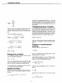
The built-in reference spectra si are stored in the spectrum library by using Fractile Integral Presentation
(FIP). The spectrum library data for an isotope is produced by measuring in the factory from 60 to 80
standards of the isotope. In this standard set there is
one subset with only chemical quench, one subset with
only colour quench and one subset with a mixture of
both. The spectra are stored in integral form reduced to
a limited number of channel values (real numbers bu, 1
< u < q) corresponding to q predetermined percentage
values (fractiles /«) of the total integral intensity
k=\
Conversion of spectrum to FIP format
where hu,k are / parameters defining the surface, ho is a
constant, and pk and rk are / coordinate pairs defining a
grid (lattice) on the surface. The constant ho and the
grid points pk and rk are the same for all bu parameters.
Differential shape of standard spectrum:
0
100
200 300 400 500
pulse height channel
+ (r-rk)2 + h0 (for 1 <u<q)
bu(p,r) =
600
Intecyal shape of standard spectrum:
100
90
/
75
/
/
50
_ lvalues
/
10
n
0
r
100
Jf
i
A complete reference spectrum is arrived at by first
computing the b« parameters, interpolating this array
and differentiating the result. Notice that errors in the
reference spectra are considered to be unimportant.
I
r,
200 300 400 500
pulse heicjit channel
600
3-2
Calculation methods
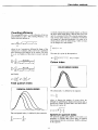
Counting efficiency
The counting efficiency e is also a function of the two
quench indices, p and r. The counting efficiency e is a
surface function defined as
(p-pkf + (r-rkf + ho
e(p,r) =
k=\
in which j denotes the pulse height channel, ul denotes
the upper pulse height limit, II denotes the lower limit
and z is a constant (=0.01). The external standard spectrum is here rather treated as a continuous distribution
c(j) instead of a discrete distribution CJ in order to facilitate greater detail in determining p which is hence
not an integer but a real number:
ul
where hk are / parameters defining the shape of the
surface, ho is a constant, and pic and rk are / coordinate
pairs defining a grid (lattice) on the surface. The error
in e, de, is a function of the errors in p and r (dp and
dr).
J
The error dp is given by the expression
dp = \-\ ^1 (l-z) • z • cot (for) = int(p))
I
ht(p-pk)
Colour index
Vip-pkf + {r-rkf + ho
k=[
I
COLOR QUENCH SERIES
V (p-pkf + {r-rkf + ho
k=\
and, finally
Total quench index
CHEMCAL QUENCH SERIES
The colour index r is defined by the equation
r=lH—where ya denotes the number of counts above the
left/right or right/left pulse height criterion limit and yb
denotes the number of pulses below this limit. Hence,
the error dr is given by
yb
The total quench index p is defined by the expression
ul
Spectrum quench index
id
The spectrum quench index SQP(I) can be used as an
alternative to SQP(E) and Colour index for quench
monitoring and activity calculations. SQP(I) is defined
by the equation
, CJ = zH>
3-3
Calculation methods
where ln(2) is the natural logarithm of 2, ti is the time
elapsed at the beginning of the counting period since
the reference time, t2 is the time elapsed at the end of
the counting period since the reference time and ti/2 is
the half-life.
id
SQP(I)=
Chemiluminescence correction
A chemiluminescence spectrum is recorded at the
same time as the normal (uncorrected) spectrum by
using the delayed coincidence principle. After measurement, the measured spectrum is corrected by subtracting the delayed spectrum from the normal spectrum channel by channel. The percentage of chemiluminescence (CLM%) is computed by the formula
where // and ul are the lower and upper limits of the
spectrum. When using SQP(I), the Colour index is assumed to be equal to the value for an uncoloured sampie.
The error in SQP(I) is expressed as:
CLM% = 100%-
ydel
ctot
2
where ydel is the number of counts in the delayed spectrum and y is the number of counts in the normal spectrum.
2
-j-(£ i a - ctot • SQP(I) )
Ctot :
1
Statistics of repeat/replicate
counting
SQP(I)2)
The mean value of n count values yi is
CtOt
yi
where c,ot = £ c;
Note: It is assumed that the counting times of all n
repeats/replicates are the same.
Background correction
If a background sample is measured, then the count
rate cj is corrected by subtraction
The theoretical standard error o; (or standard deviation) of each measurement is equal to Vy/. The standard error a of the n measurements is equal to
Cjcorr — Cj — Cjbkg
where cja>ir is the corrected count rate in channel j and
cjblcg is the measured count rate in channel j . In this
case the correction is made before spectrum fitting.
If a background value is submitted, then the count rate
xi is corrected after spectrum fitting.
(n-1)
while the observed standard error oy<l of the mean is
equal to
Half-life correction
Half-life correction is performed on the count rate x
and the activity a after spectrum fitting by using the
equation:
\e
U/2
^
0
Ov,,=
The theoretical standard error ay, of the mean is equal
to
—e
3-4
Calculation methods
The theoretical standard error ay, can be _ compared to
the observed standard error Oyo by using the reduced
%r ("Chi-square") value:
2
°y<>
The degree to which %r deviates from unity is a direct
measure of the extent to which the observed error deviates from the theoretical. %r multiplied by the 'degrees of freedom' (=n-l) can be used to determine a
probability that a random sample from a normal distribution would have a larger (or smaller) value of %
than the observed value.
List of symbols used
a - activity (DPM)
b = FIP channel
c = measured total count rate (CPM)
cj ~ measured channel count rate (CPM)
C = an array (or column vector) comprising the measured count rates cj
d = error in function or parameter
e = counting efficiency
/ = tractile value
gi,i = diagonal element of matrix G
G = the matrix (ST*W1*S)'1
h = surface function parameter
i = index to isotope
j = index to channel
k = index to surface function parameter
/ = number of parameters defining the surface
m = maximum number of isotopes
n = maximum number of channels or number of repeats/replicates
p = total quench index (SQP(E))
q - number of fractiles/
r = colour quench index (Colour)
si — reference spectrum, a column in S
sjj = channel value in reference spectrum, an element
in the matrix S
S = a matrix containing the reference spectra .?;.
t - counting time or elapsed time
ti/2 = half-life
it = index to fractile/and FIP channel b
WJ - weight value for channel j , a diagonal element in
the matrix W
W = the weight matrix
x\ = unknown total count rate for isotope i, an element
in the array X
xij = unknown channel count rate for isotope i
X = an array (or row vector) comprising the count
rates x;
y = number of counts
z - fractile for total quench index p
O = standard error at 68.3% confidence limit ( = standard deviation)
Xr = reduced chi square
4 Quality control information
QC Contents
QC Contents
Quality Control Certificate
1099 0045
Final Test Data Sheet
1096 0594
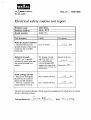
Electrical Safety routine test report
1096 1059
Safety evaluation of the Eu-152 source and ext. std. transport system
1099 0196
Quality control report
1096 1060
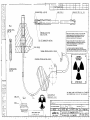
External standard transport system
1036 1092
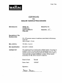
Certificate for Eu-152 source
Certificate for unquenched LSC standards
„
1095 7794
1390 0171
PROTOCOL
DATE
TIME
ID
5
1 MAPPING
! 1998/02/11
5 15526
5 P01SS030
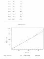
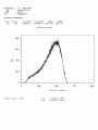
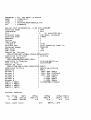
Quench Standardization
Wai lac 1400 DSA ver 2.50 S/N 4140189
DPM
Counting mode
SQP(E)
Quench index
H3
Isotope(s)
= ,12.43 y
H3
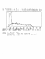
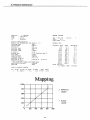
MAPPING
Protocol name
600
Counting time
194500
Activity (DPM)
0.01
2 sigma X
0.00 Checking time: 10
Minimum cpm
Clear
Vial type
Xylene
Liquid system
Hal-f li-fe
Advanced modes
Halflife zerotime
1997/07/01 , 105005 00
Zerotime of H3
Output to Printer
CTIME5 CPM1,CPMer1,EFF1,SQPE,SQPEer
Additions to Printer
Li sting
Spectrum
Beta
Quench standard
CTime
600
H3__CPMer
H3_CPM
1945.0
E E P R 0 M
LRC
samples?
H3
0. 00
L I
199 AO =
1 „0 0
T I N G
100 Al =
25.0
T E M P =•••
112
CONV STEPS
M a p p i n g
Channels! WLIB
0. 0
d a t a
TRUE
o. o
TRUE-WLIB
0.0
47.9
58.6
10.7
93.3
98,2
4.9
137.8
137.
-0.
156. 1
154. &
•1.5
173.9
171. 9
--2. 0
SQPE
965-15
SQPEer
0.04
191.7
189. &
..... *".= "!
210.6
208.6
•1.9
(3 / / . £
692= 4
15,2
740.9
765.3
24-4
793,3
831.5
38,
880.6
965.1
84™ 6
889.2
979,
90.3
915.3
1023.0
107, S
a p p j . n g C u r • v >-•
:i. 6 . 8@ .„
+
•+•
_...---•"
7. 58 __
+.-••"
CO
r5.ee _
u
LU
2=58
i
r
r
r
r
500
i
i
'59
WLIE ch
Total activity;
H3
194500.0 DPM
3.242 kBq
: 9
3H, 14C, BG Wai lac std
: 1998/02/13
s 16^33
3 P09AS018
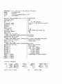
PROTOCOL
DATE
TIME
ID
Wai lac 1414 WinSpectral vl 30 S/N 4140189
Counting mode
5 CPM
Isotope(s)
5 H3,C14
H3
5- 350,12.43 y
C14
5- 660,5730.00 y
Protocol name
3H, 14C, BG Wailac std.
Counting time
1200
Repeats
4
Cycles
1
Replicates
1
2 sigma 7.
0.30
Minimum cpm
0.00 Checking times 10
Output to Printer
POS,CTIME,CPM1,CPM2,SQPI , SQPE
Additions to Printer
Listi ng
Output to Display
POS,RACKPOS,CPM,RPT,SQPI ,CPM1,CPM2
Additions to Display
Listing,Spectrum
"Spectrum
Beta
Window
Window
Wi ndow
Window
Wi ndow
Window
FNCT1
FNCT2
FNCT3
FNCT4
1-1024
1-1024
1-1024
1-1024
1-1024
1-1024
1
7
3
4
5
6
=
=
=
~
/Beta
/Beta
/Beta
/Beta
/Beta
/Beta
FNCT1
FNCT2
FNCT3
FNCT4
Unknown samp 1 es'•
Pos
CTime
1
1
1
1
'*?'?'?
127507. .1
127563.1
SQP I
176.41
175.94
176.00
176.01
SQPE
966.42
966.12
965.14
965.16
127509.8
76.7
176.09
0. 22
REPEATS
965.71 = Mean
0.66 = St.Dev
H3_CPM
C14_CPM
26908.0
27007.7
27140.1
26906.3
102616.2
102489.5
102521,8
102098.8
SQP I
419.89
419.50
419.29
419.38
963.68
961.01
961.53
963.36
26990.5
110.4
102431.6
228.3
419.52
0. 26
REPEATS
962.40 ~ Mean
1.32 = St.Dev
H3_CPM
C14_CPM
23.8
23.2
23.2
24. 1
SQP I
388.55
389.95
412.37
407.87
SQPE
965.66
967.15
966.59
968.22
23.6
0.5
399.69
12.20
966.91 ~ Mean
1 .07 = St.Dev
223
223
223
H3_CPM
127295,2
127472.4
127405.0
127462.2
C14_CPM
127402.2
127566.7
222
0
127408.7
81.3
CTi me
274
275
275
276
275
0
Pos
CTi me
3
1200
1200
1200
1200
16.8
17. 1
15.9
16.7
1200
16.6
0. 5
•
Pos
2
2
2
*?
-—
SQPE
-
REPEATS
0
Total. count rates
H3
C14
1544 15.9 CPM
229964.9 CPM
PROTOCOL
DATE
TIME
T
D
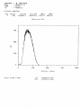
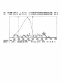
5 8 SPECTRUM
! 1998/02/16
2 09-: 35
s P08AS016
Unknown samples"
Pos
1
CTime
120
H3_CPM
127526.4
C14_CPM
127612.9
SQPI
175.77
SQPE
966.40
Spectrum Plot
758 _
598
a.
o
259
Ch anne1 numb er
Total count rates
H3
C14
127526.4 CPM
127612.9 CPM
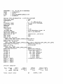
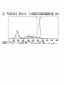
PROTOCOL 2
iTE
s
S SPECTRUM
1998/02/16
: 095 40
2 P0SAS017
TIME
ID
Unknown sampless
Pas
CTime
H3_CPM
C14_CPM
SQPI
SQPE
2
120
27225.9
102986.0
4IB.90
963.06
Sp ec t r urn P1 ot
400 —
388 _
aj
208
189 __
758
Channel
Total
count
rate'
H3
C14
n u. m b e r
27225=9 CPM
102986.0 CPM
i 888
PROTOCOL
DATE
TIME
FILE
ID
"•
s
!
s
5
15 14C Benz. protocol
1998/02/17
16803
AsS4140189SP15AS016.TXT
P15AS016
C-4
Wai lac 1414 WinSpectral vl.30 S/N 4140189
CPM
Counting mode
C14
Isotope(s)
C14
5- 660,5730.00 y
Protocol name
14C Benz. protocol
Counting time
14400
Repeats
1
Cycles
1
"^epl icates
1
2 sigma 7.
0.50
Minimum cpm
O.OO Checking time* 10
Advanced modes
PSA,PAC
PSA level
85
PAC level
163
Output to Printer
POS,CTIME,SQPI,CPMwl, CPMw2,CPMw3,FNCTl
Listing
Additions to Printer
Output to Display
POS,RACKPOS,CPM,SQPI,CPM1
Additions to Display
Li sti ng,Spectrum
asS4140189
Path of File
Output to File
,FNCT1
POS,CTIME,SQPI,CPM1,
Spectrum,Listing
Additions to File
Beta
Spectrum
200- 500 /Beta
Window 1
200- 500 /PACRejfl
Window 2
200- 500 /Alpha
Window
1-1024 /Beta
Window 4
1-1024 /Beta
Wi ndow 5
1-1024 /Beta
Window 6
(1OO*CPMW1/103600)
FNCT1 = FNCT1
FNCT2 = FNCT2
FNCT3 = FNCT3
FIMCT4 = FNCT4
Unknown sampless
Pos
1
2
CTime
115
14400
SQPI
339.50
478.95
Total count rates
CPMwl
78617.2
1.2
CPMw2
2381.9
0.4
C14
CPMw3 FNCT1
1225.1 75.9
0.1
0.0
88774.1 CPM
[A] 390.000 CPM/ch
1.81 win
0.052 CPM/ch 231.14
T
*-*—1
A:\4140189SP15AS016SS0010101.001
A:S4140189SP15AS016NS0020101.001
SPtt 1
SPtt 1
• r
800
980
1000
1
100 200 300
400
500
600
700
INTEGRC 288-491) [A] 77678.805 CPM [B]
1.177 CPM
BUNCH^ 4 * FM * (103608.00 DPM)
FM ttA],[B]}= 4777 (E= 74.98
PROTOCOL
DATE
TIME
FILE
ID
:
:
!
i
J
16 3h qs 8+12 PROTOCOL
1998/02/17
20!07
AiQ4140189QP16AS017.TXT
P16AS017
Wallac 1414 WinSpectral vl.30 S/N 4140189
Counting mode
CPM
Isotope(s)
H3
H3
5 350,12.43 y
Protocol name
3h qs 8+12 PROTOCOL
Counting time
14400
Repeats
1
Cycles
s 1
Replicates
s 1
? sigma %
s 0.30
.linimum cpm
s 0.00 Checking times 10
Advanced modes
Half life,PSA,PAC
Halflife zerotime
Zerotime of H3
s 1993/04/01 ,00500:00
PSA level
205
PAC level
120
Output to Printer
POS,CTIME,SQPI,CPMw1,CPMw2,CPMw3,FNCT1
Additions to Printer
Listing
Output to Display
POS,CTIME,SQPI,CPMwl,CPMw25 CPMw3,FNCT1,RACKPOS,CPM,CPM1,RPT,DPMI
Spectrum,Listing
Additions to Display
a:Q4140189
Path of File
Output to File
POS,CTIME,SQPI,CPM1,CPM2,CPM3,FNCT1
Additions to File
Spectrum,Listi ng
Spectrum
Alpha,Beta,PACRejft
20-'200 /Beta
Window 1
"lindow 2
2 0 - 200 /PACRejtf
Window 3
2 0 - 200 /Alpha
Window 4
1-1024 /Beta
Window 5
1-1024 /Beta
Window 6
1-1024 /Beta
FNCT1 = FNCT1
<1OO*CPM1/(207500))
FNCT2 = FNCT2
FNCT3 = FNCT3
FNCT4 - FNCT4
Unknown samples:
Pos
1
2
CTime
742
14400
SQP I
112.01
376.98
Total count rates
CPMwl
37358.6
4. 1
CPMw2
1012.3
0.2
H3
CPMw3 FNCT1
2229.9 23.8
1.5
49359. 1 CPM
0.0
[A] 550.000 CPH/ch
EB]
8.160 CFM/ch
11.82 m i n
231.06 min
AA4140189SP16AS017SS0010101.001
A:S4140189SP16AS017SS0020101.001
1
100 200
300
400 500
INTEGRC 50- 143) [A] 31700.805 CPM CB]
BUNCH= 4 * FM * (158020.97 DPMco)
FM
Isotope;
STANDARD
H-3
Half L i f e =
preparation date
measurement date
decay r a t i o
(A/Ao)
12.43 Y
= 01.04.93 12:00
= 17.02.98 12:00
= 0.7615
600 700
2.021 CPM
800
199
900
SPtt 1
SPtt 1
1008
(E= 20.06 '/J
207500.00 DPM
158020.97 DPM (decay c o r r . )
PROTOCOL
DATE
TIME
FILE
ID
5 17 Am & Sr & Bg 0phs3 protocol
'• 1993/02/ IS
i 005 23
: A5S4140189gP17AS001.TXT
s P17AS001
Wallac 1414 WinSpectral vl.30 S/N 4140189
i CPM
Counting mode
8 H3
Isotope<s>
5- 350,12.43
H3
Protocol name
Am ?! Sr
Bg 0phs3 protocol
Counting time
14400
Repeats
1
Cycles
1
Replicates
1
1 sigma 7.
1.00
flinimum cpm
0.00 Checking time 10
Advanced modes
PSA
PSA level
38
Output to Printer
POS,CTIME,SQPI,CPMw1, CFMw2,CPMw3,FNCTl
Additions to Printer
Listing
Output to Display
POS,CTIME,SQPI,CPMw1, CPMw2,CPMw3,FNCT1,RACKPOS, CPM, CPM1
Spectrum,Li st i ng
Additions to Display
as^4140189
Path o-f File
Output to File
POS,CTIME,SQPI,CPMw1, CPMw2,CPMw3s FNCT1
Additions to File
s Spectrum,Listing
Spectrum
Alpha,Beta
570- 670 /Beta
Window 1
570- 670 /Alpha
Window 2
1-1024 /Beta
Window 3
Window 4
1-1024 /Beta
Window 5
1-1024 /Beta
1-1024 /Beta
Window 6
(1OO*CPMW2/(CPMW1+CPMW2))
FIMCT1 = FNCT1
FNCT2 = FNCT2
FNCT3 = FNCT3
FNCT4 = FNCT4
Unknown
Pos
1
2
3
sampless
CTime
12542
292
14400
SQPI
339.48
548.63
389.54
Total count rates
CPMwl
13.0
1507.2
6.3
CPMw2
9881.6
7.7
0.3
H3
CPMw3 FNCT1
199.1 99.9
8539.2
0.5
49.0
4.0
1296.2 CPM
[A] 240.000 CPM/ch 200.91 min
0.060 CPM/ch 231.09 min
A:S4140189SP17AS001SS0010101.001
A:S4140189SP17AS001SS0030181.001
1
100 200 300
400 500
INTEGRC 584- 657) [A] 9404.063 CPM CB]
BUNCH= 4 * FM * ( 9894.68 DPM)
FM
SPtt 4
SPtt 4
600 700 800 900 1000
0.195 CPM
^ 46385 CE= 95.04 yJ
1096 0594
WAIIAC
AN
COMPANY
FINAL TEST DATA SHEET (FTDS)
INSTRUMENT
S/N:
HV - GENERATOR
EPM-A OUTPUT
v L=
i<m
PMT VOLTAGE
(calculated)
VOLTAGE DROP *
OVER RFA (RRH)
R=
GUARD
Hi
V
Hi<{
V
n^a
v
'sirs
v
G1 =
G2 =
V
V
LINT =
EBU - INTEGRATORS
RINT =
V
* DVM input impedance 10 MD.
PERFORMANCE WITH SUPPLIED STANDARDS
H-3
E%
BG
C-14
SQP(I)
SQP(E)
BG
E%
SQP(I)
an
l-q-
Base mapping data
LRC VALUE =
Od
LRC C1 (AO) =
1d
LRCC2(A1) =
2d
CONV. STEPS =
ha
"6
3d
0
4d
o
WAIIAC
UNQUENCHED LSC STANDARD
for
Liquid Scintillation Counter
Product No.: 1215-111
CERTIFICATE
Radioactive isotopes: tritium, carbon-14 and blank
The absolute activities of standards and the reference
dates for all standards are as follows:
3
H : 194500
dpm 1. Jul 1997
Ref. Date
14
C : 106000
dpm
Nov1997
Ref. Date
Feb 1997
Ref. Date
Blank:
The 1215-111 is from the production Lot No.: 9702 A ;
Product Description: The 1215-111 Liquid Scintillation
Standards set consists of two activity standards and one
blank standard. The activity standards are precisely
calibrated, sealed unquenched samples of carbon-14
labelled [1-14C] stearic acid and tritium labelled [7(n)3H]-cholesterol in 10 ml of xylene based scintillation
solution. The labelled compounds are produced by
DuPont NEN, Belgium and Amersham International, UK.
The unquenched blank standard is a sample of 10 ml of
xylene based scintillation solution. The standards are
supplied in 20 ml capacity low potassium content
Wheaton vials. These are flame-sealed and secured
with white silicon mastic and an aluminum cap.
Str>ndards are deoxygenated with pure nitrogen before
t Jing.
Definition of Use: The 1215-111 unquenched standards
set is intended for use with LS-counter Serial No:
¥N0^j
to calibrate the instrument and measure day-to-day 3 H and
14
C counting efficiencies and background for comparison
with original factory specifications and for verifying stable
system performances. For specific instructions on the use of
these standards with an LS-counter, the Instrument manual
should be consulted.
Precautions on Storage and Use : Fluors are susceptible
to photo-chemical degradation. The standard set should be
stored in a dark place at room temperature. Recommended
shelf-life is not more than 5 years.
Activity Calibration :
The tritium standards are
calibrated against reference standards of tritium labelled
toluene by the National Institute of Standards and
Technology (NIST),
Standard Reference Material
(SRM) No. 4947C, the estimated accuracy of which was
+ 1.2%. The Carbon-14 standards are calibrated against
reference standards of n-hexadecane-1-14C supplied by
the National Institute of Standards and Technology,
Standard Reference Material (SRM) No. 4222C, the
estimated accuracy of which was + 0.81%. The absolute
activity of the standards is within + 0.5% of the reference
standards of NIST SRM's.
On behalf of the Quality Control Department
V JacOy
P.O. Box 10
SF-20101 Turku
Finland
1390 0171
WAIIAC
AN J^EGsJS
Doc. no
COMPANY
10961059
M. Ala-Uotila
Electrical safety routine test report
Product name
Product number
Serial number
1400 DSA
1414- 00-3
4140*^1
Test description
Limits
Protective Earth Continuity
Measured between the
ground terminal of the mains
connector and accessible
metal parts.
Dielectric Strength
1500 V AC is applied
between the mains input and
the ground terminal for 1
minute.
Test results
c.c^
max. 0.10 ohm
The leagake current
rejection limit is 12.5
mA, including the
current through EMI
suppression capacitors.
|
ohm
Result of the test
Signature
'H
(Defined in the UL-Client's Test
Data Program)
Earth Leakage Current
The current through the
ground lead is measured
during normal operation.
The test is repeated with
mains polarity reversed.
oau
max. current 0.50 mA
max. current 0.50 mA
mA
mA
The tests have been performed with the measuring equipment which belong to the regular
Wallac calibration program.
Tests performed by:
Date:
1390 3693
WAIIAC
AN Ji^BBia
DECLARATION OF CONFORMITY FOR CE-MARKING
COMPANY
We
Supplier's name
WALLAC OY
Address
PL 10, 20101 TURKU, FINLAND
declare under our sole responsibility that the product
Name, type or model, lot, batch or serial number, possibly sources and numbers of items
1414 Liquid Scintillation Counter
Valid from serial number 4140044
to which this declaration relates is in conformity with the following standard(s) or other normative document(s)
Title and/or number and date of issue of the standard(s) or other normative document(s)
EN 50082-1 :1992 ; EN 50081-1 :1992
EN 61010-1 :1993
(if applicable) following the provisions of the following directives
Electromagnetic compatibility (EMC), 89/336/EEC
Low voltage (LV), 73/23/EEC
Place and date of issue
12 Nov. 1997 Turku, Finland
Name and signature or equivalent marking of authorized person
Heikki Kouru, Quality Assurance Manager
_
WAIIAC
AN
COMPANY
1096 1060
Quality Control Report
Name of Product:
Manufacturer:
Function Tested:
Activity of the capsule:
1400-Series Liquid Scintillation Counters
WaIIac Oy, Turku, Finland
Classification of External Standard Capsule Eu-152 according
to ISO 2919.
440 kBq
CERTIFICATION
Eu-152 External standard source has been tested according to ISO 2919 - 'Sealed Radioactive
Sources - Classification'.
The tests are:
Test
Class
Short definition
Temperature
4
Ext. pressure
Impact
Vibration
3
4
3
Puncture
4
- 40 °C (20 min)
+ 400 °C (1 h) and thermal shock to 20 °C
25 kPa abs. to 2 MPa abs.
2000 g from 1 m
2 times 10 min, two axes
25 Hz to 50 Hz/5G,
50 Hz to 90 Hz/0.635 mm amplitude,
90 Hz to 400 Hz/lOG
50 g from 1 m
Leakage tests according to ISO TE.. 4826 have been performed after the classification tests.
The tests show no significant leakage.
The source fulfils ISO 2919 requirements and is therefore classified as C43434.
Date: 25 Nov. 1994
Signature of controller
Raimo Kananen, M.Sc.
Physicist
Quality Assurance Department, Instruments
1099 0196
November 1995
Evaluation of the safety of the Eu-152 external standard source in
Wallac 1400 series LS counters
Isotope
Europium 152.
Maximum activity
12 microcuries (half-life 13.5 years).
Origin of radioactive material
The Eu-152 radioactive material is made by the Radiochemical Centre, Amersham, England.
Manufacturer of the standard capsules
The Eu-152 standard capsules are manufactured by Wallac Oy, Finland.
Manufacturing process
The manufacturing process by which the radioactive standards are produced involves two steps: the preparation of
the radioactive material and the encapsulation of this material with a metal cover.
In the manufacturing process the active Eu-152 solution (1 mCi/ml) is absorbed homogeneously into crystalline
synthetic zeolites in such a way that the activity of each active source is 12 (iCi.
The active source is enclosed in a stainless steel shield of thickness 0.35 mm. The source is sealed first with
silicon rubber and then the shield is closed by using a stainless steel pin, which is held in place by pinching the
shield with a special tool. The wire that moves the capsule is then inserted into the shield and fixed in place by
again pinching the shield.
ISO-test
The capsule has been tested by the Quality Assurance department of Wallac Oy according to the ISO 2919
standard. The rating C43434 has been achieved.
External standard transport system
The transport system is illustrated in document 1036 1092.
The standard is mounted on a metal wire which is moved by two friction wheels controlled by a stepper motor and
two sensors.
The capsule has two stable positions in the transport system; one in the storage shielding and the other in the
measuring chamber inside the lead shielding. The storage shield is made of lead (thickness 50 mm) and is
equipped with a radiation hazard warning label. This includes a definition of the isotope and its activity.
The capsule is transported to the measuring chamber along a PA (polyamide) tube and a stainless steel elevator
tube. The transport time is less than 3 seconds.
Disposal of the capsule
When the instrument is no longer in use, the Eu-152 standard capsule must be removed and sent to the appropriate
radiation safety authorities or to Wallac for safe disposal. This procedure must be performed only by a qualified
Wallac service engineer.
STAINLESS STEEL I AISI 303!
STAINLESS STEEL (AISI 303)
WIRE (STEEL)
PET Y
STAINLESS STEEL
PRESSED WITH THE
AID OF A TOOL
Eu-152
RADIOACTIVE
When this instrument is no longer in use the Eu-152
standard capsule must be removed and sent to the
appropriate radiation safety authorities or to the
instrument manufacturer for safe disposal.
MATERIAL
STORAGE POSITION CONTROL
Oes que cet instrument n'est plus employe la source
standard de Eu-152 doit etre enlevee et envoyee aux
autorites de radioprotection ou au fabricant de
I'instrument pour elimination.
Kun tama laite poistetaan lopullisesti kaytdsta.
on Eu-152 standardi-kapseli irroitettava|a taimitettava
sateilyturvallisuusviranomaisille tai laitteen valmistajalle
SENSOR
CAUTION
RADIOACTIVE
MATERIAL
MEASURING POSITION CONTROL SENSOR
STAINLESS STEEL
O
SATEILYVAARA
O
•C3®
LEAO
j»rs,..l j
THE ABOVE LABELS ARE PERMANENTLY ATTACHED TO
THE EXTERIOR REAR PLATE OF THE INSTRUMENT -
SHIELD
(THICKNESS
40mm
Rent 0H13
ELLEI TOISIN MAARATA.
|
—r
-l
1
r
1
1
941212 HKY
".-941212
"'"' Eu-152 EXT. STD. TRANSPORT SYSTEM
FOR 1400-SERIES LSC-COUNTERS
10 I K EX) OF TK wBt
1
1
1
1
1
1
r
_ —
r
Sunje
^j
10 361092
-i
r
1095 7794
WAIIAC
CERTIFICATE
for
SEALED RADIOACTIVE SOURCE
Manufacturer:
WaIIac Oy
P.O.Box 10
20101 TURKU 10
FINLAND
Batch No: 7C
Serial No:
Description of the
Radionuclide:
EU-152 gamma source in stainless steel shield of thickness
0.35 mm.
Active length 1.3 mm.
Max. activity:
440 kBq (12u€i)
ISO classification:
Leakage test:
ISO 2919 C43434
The sealed source is immersed in distilled water. The water is
heated to 323 ± 5 K and held at this temperature for 4 h. The
sealed source is then removed and the activity of the water is
measured with a liquid scintillation counter. Activity levels
exceeding 185 Bq will be cause for rejection.
Result of test:
Passed
Date of test:
15/09/97
Signature:
5 Installation information
1099 0045
March 1991
WAIIAC
AN
EGsG COMPANY
QUALITY CONTROL
CERTIFICATE
PRODUCT INFORMATION
WALLAC
14 14
LSC
Name of product:
1 4, l 4 — O O 3
Product type no:
4 14 O18 9
Serial no:
Sample capacity:
PHOTOMULTIPLDER TUBE INFORMATION
position
size
type
serial no.
"IL.,
2
INCH
R.3 3 1 — 1 3
CG446 1
R.
2
INCH
R. 3 3 1 ••- 1 3
C G432 2
ACT9 3 O 2
GL.,
O .. '7 5
INCH
R. 1 1 €> 6 — 1 O
GR
O -, V 5
INCH
R .1.. 16 6
1O
!1K 2 5 9 2
CERTIFICATE
This is to certify that this instrument and its components and subunits have been
tested according to the Wallac Instrument Quality Control plan, and that it fulfils
the specified quality and performance values.
Details of this plan can be obtained from your local Wallac representative.
Date:.../.
Signature:. .yft
On behalf of me Quality Control Department
1(1)
1086 1430
September 1995
Warning
This equipment must be installed and
used in accordance with the
manufacturer's recommendations.
Installation must be performed by
properly trained and authorised
personnel.
Failure to follow these instructions may
invalidate your warranty and/or impair
the safe functioning of your equipment.
Please contact your local Wallac
representative for installation.
WALLAC
Installation information
Installation
Environment
Normal clean laboratory conditions usually provide a
satisfactory operational environment, but the following
points should be taken into consideration.
Ideally a separate room should be provided for your
Wallac 1414 WinSpectral counter as this allows the
best control over the immediate environment. Ventilation should be adequate for all conditions of use, the
temperature should be reasonably constant at about
22°C, relative humidity should not be excessive, and
direct sunlight should not be able to reach the instrument. It is also important that the various isotopes are
stored well away from the instrument in another room.
Only those radioactive samples that are actually being
measured should be in the laboratory at any time in
order to keep the background at a low level.
Electric power
Three electrical outlets should be available, with, if
possible, a separate power line for the instrument itself
having an isolation switch and a fuse box. If excessive
fluctuations in the mains voltage are anticipated, a
mains stabilizer may be necessary.
Unpacking
To unpack the instrument proceed as follows (see fig.
5.1).
Fig. 5.1 Unpacking the instrument and accessories
Cut off and remove the binding bands. Open the
clinching nails and lift off the cover. Unpack the separate packages. Then open the lower clinching nails and
remove the box. Unscrew the fixing screws. Lift the
instrument up from the shipping package base and unscrew the suspension bushes from the frame.
Check all units and accessories against the packing
list. Note any possible transport damage.
Move the instrument to its place of operation.
Installing the lead shielding
Remove the screws holding the back panel (fig. 5.2).
Fig. 5.2 Removing the screws
5-1
Installation information
Remove the back panel (fig. 5.3)
Fig. 5.3 Remove the back panel
Fig. 5.6 Releasing the inner cover
Pull the top cover forward and remove it (fig. 5.7).
Unscrew and remove the PC board (fig. 5.4).
Fig. 5.4 Remove the PC board
Fig. 5.7 Pull the top cover forward
Install the lead shielding for 1414-001 WinSpectral as
shown (fig. 5.8) the lead sections are numbered.
1
2
1
3
Unscrew the top cover screws (fig. 5.5).
Fig. 5.8 Installing the shielding for WinSpectral
In the case of
1414-002
WinSpectral a/p, first
place the two identical pieces of lead
Fig. 5.5 Releasing the top cover
shielding
5-2
'9- 5 - 9
with aSSKSfor
metal supports on
top of the PMTs
around the tube for
the counterweight,
see fig. 5.9.
Remove the additional screws securing the inner cover
(fig. 5.6).
F
WinSpectral
a/p
Installation information
When you have done this, proceed with the following
instructions, which are the same for 1414-002 WinSpectral a/p and 1414-003 Guardian; see the following three figures.
The shielding should be installed in the order shown in
fig 5.10).
4
1
3
Fig. 5.10 Installing the shielding for
WinSpectral cx/p and Guardian
There is additional shielding to install around the vial
sensor (fig. 5.11) and under the instrument on the
bench (centred on the elevator), see fig. 5.12.
Installing the stand-by power
supply fuse
During transportation the stand-by power supply is
disconnected. Install the fuse after the lead shield installation (fig. 5.13).
t\
/
Fuse
Fig. 5.13 Stand-by power supply fuse
Replace the instrument covers.
Installing the PC keyboard shelf
Assemble and fix the PC keyboard and mouse shelf
(product number 10860862) and the monitor stand
(1414-160) following the instructions supplied with
them, see fig. 5.14.
Monitor
stand
Diskette drive
behind cover
Fig. 5.11 Extra shielding for WinSpectral a/p and Guardian
Keyboard
shelf
Fig. 5.14 WinSpectral peripherals
Checking the mains voltage
setting
Measure and note the mains voltage at the outlets to be
used.
IT
\
Extra shielding
Locate the mains selector switch, this is on the left
side when looking at the rear of the instrument. If necessary adjust the mains selector switch to correspond
with the measured supply. For supplies with a nominal
/
Fig. 5.12 Extra shielding underneath WinSpectral a/p and
Guardian
5-3
Installation information
WinSpectral
1
Cables (Options]
1221-470 (9 pin)
1221-503 (9 pin with shielding]
1221-459 (25 pin)
PC
LPT1
Windows
printer
Any LPT or
nerworK primer
Cable 1224-122
Raw data printer
Any Epson Fx compatible
Fig. 5.15a Cables when raw printer connected to PC
WinSpectral
PC
Windows
printer
PC port 2
Printer
port 1 Cable 1221-456
(serial
line)
Raw data printer
Any Epson Fx compatible
Fig. 5.15b Cables when raw printer connected to WinSpectral
Note: The factory settings of the printer may
not correspond to those used in WinSpectral.
If printing does not function properly, check
the settings according to the information
given in Serial port settings
voltage of 230 V it is recommended that the selector
be set to 240 V.
can have it connected to WinSpectral directly in port 1
(fig. 5.15b).
Check that the fuses fitted in the fuse carriers on the
back panel are of the correct rating for the local supply, and according to the label.
The PC is connected to port 2 of the counter.
The third port is not used and should have a blanking
connector (1086 0713).
Connecting the counter and
peripherals
Further details of the settings for the printer are given
in its own installation sheet which follows these installation instructions.
Connect the counter to the PC and the printer(s) using
the cables shown in fig. 5.15 above. As well as the
normal PC Windows printer e.g. a network laser
printer, you can also have a raw data printer. Normally
this will be connected to the PC (fig. 5.15a), but you
Plug in the power cables for each device.
5-4
Installation information
Load some racks with ID labels, then start counting
and check that the instrument will change the protocol
as required by the labels.
Installing the PC software
Install the WinSpectral following the instructions in
the User manual.
Performance test with Easy GLP
After installation, start the program by double clicking
the 1414 WinSpectral icon in the WinSpectral window.
To define the proper values for GLP you have to make
an initial measurement of the local background. Make
sure that all stationary and moving gamma sources are
removed from the neighbourhood of the instrument.
Use at least 300 s measurement time.
When the WinSpectral main window appears, you will
see at the bottom the status bar; this is divided into
four sections. In the third and fourth there are the date
and time respectively. In the second there is a message
about the communication status. If the counter is not
switched on then there will be a message "No response
from counter".
Start the editing of the Easy GLP protocol (see page
52 in the User manual). Type the values of the supplied standards into the text box marked Reference
samples. The isotope windows are 5-350 for H and
5-650 for C. The measurement time should be 300 s
or longer and the precision 0.5%.
Starting the counter
Lift the instrument cover and then the diskette drive
cover. This latter should be lifted straight up first to
release it. Then insert the instrument program diskette
into the diskette drive in the counter and replace the
cover. Do not remove the program diskette.
Test values are as follows (where FTDS means the
Final Test Data Sheet included with the Instrument
manual):
Min
Max
H efficiency
H SQPXI)
C background
-3%
-5ch
+ 1%
+3ch
C efficiency
C SQP(I)
-2%
-5ch
+ 1%
+3ch
Switch on the counter. The message on the status bar
will change to "Counter online". During the loading
process the status bar will show the following messages: "Loading DOT", "Loading texts" and "Loading
1400 program". When the program is completely
loaded, the message "Counter idle" will appear. Loading takes some 2 minutes.
' H background
Note: The program diskette labelled BACKUP may
also be used but be sure to always have a program
diskette in addition to the one in the instrument. When
needed make a backup copy using the "Backup instrument disk" function in the System menu. It is also recommended that from time to time you make a backup
copy of your program diskette to save your own protocols and spectrum libraries.
14
3
Comment
Use the local
background*
from FTDS value
from FTDS value
Use the local
background*
from FTDS value
from FTDS value
*The minimum and maximum background warning
limits for GLP are calculated from "the value measured during installation +/- 3o". Some example backgrounds and 3a limits are:
Observed background
46-50
41 -45
36-40
31 -35
26-30
21 -25
16-20
11 - 15
6 - 10
0-5
Note: You should also make backup copies of the
WinSpectral program diskettes before use. Use e.g. the
Copy disk function in your Windows File manager.
Carrying out a functional check
of the instrument
For checking the instrument mechanically and for
checking the function of the ID reader proceed as follows:
5-5
3a
9.5
9.0
8.5
7.9
7.3
6.7
6.0
5.2
4.2
3.0
Installation information
E.g. if your background is 21 then 3a is 6.7 which
means the minimum and manximum limits are 14.3
and 27.7 respectively. You can calculate the 3a from
the expression 3a = 3 * SQRT (BGD/t) where BGD is
the measured mean background rate in the window
and t is the counting time in minutes.
Note: a typical change in efficiency of 2% for H over
a period of a year may be expected.
Serial port settings
The factory settings of the printer serial port on WinSpectral are as follows:
Baudrate:
4800 PC
Parity:
No
Data bits:
8
Stop bits:
2
Handshake:
DTR i.e. ESN
These settings may be changed by selecting System
parameters in the System menu. See the User manual
on page 71.
5-6
MultiCalc installation
MultiCalc installation
Introduction
If you are planning to use MultiCalc to handle results
from Wallac WinSpectral, please follow the installation instructions below in addition to the normal MultiCalc installation procedure.
- do normal the MultiCalc installation (see the MultiCalc Installation module in the Supervisor's manual)
and select Fl Yes for the question "Exit MultiCalc
Yes/No".
- now use the Windows Program Manager and copy
the icon WinSpectral to the StartUp group. To do this,
drag it from the WinSpectral group to the StartUp
group while you hold down the CTRL key.
Changes to Autoexec.bat
- start up Windows
- with File Manager copy the file c:\1400w\mc\winbeta.cOl to the directory c:\wiacalc\Ocom
- create the directory c:\wiacalc\Ocom\winbeta
- create a new program in the Windows StartUp group:
click Browse to select c:\1400w\mc\WIA.PIF.
Edit the MS-DOS Autoexec.bat file. (Use Windows
Notepad or a DOS editor to do this).
Make sure that you have there the command COMRS
and that it has the parameter 00000000 i.e. eight zeros.
This is to force MultiCalc not to use serial ports at all.
Otherwise you will get the question about who should
use the C0M1 or COM2 port, the Windows application or the DOS application when MultiCalc is started.
- start MultiCalc by double clicking that icon
While you are editing the Autoexec.bat file, add also
there the command WIN to make Windows start automatically after a bootup.
- select Level 5 (if your starting level is 3 or less then
press F7 LEVELS then F4 Level 4 and then again
LEVELS (F7) and Level 5 (F5))
Setting up a protocol in
MultiCalc
- select the System properties to be AOSPMTIV (follow the sequence: F7 SYSTEM F8 ETC F3 COMM
PROT F4 PROPERTY, select the protocol winbeta
and then type in the properties)
In WinSpectral, go to System/Options/Directories and
give the MultiCalc assay path as:
C:\WIACALC\0COM\WINBETA.
- go to the MultiCalc main menu by pressing ESC
ESC ...
From the MultiCalc main menu select F4 PROTOCOLS and create a new protocol. The name should be
a short one, e.g. MCASS. Select the protocol type, e.g.
RATIO and edit the the protocol or use the default
settings. Save the protocol.
- create a startup macro for MultiCalc as follows:
Press Ctrl A
Select MACROS
Select CREATE
Enter @ as the macro name
Select level 2
Press Enter as the comment
Press function key Fl (this is the body of the macro
and it means that the program will go to COUNTER).
Now the macro is complete and should be ended by
pressing the ESC key.
After you exit from Protocol editing, go to the main
menu and select from there Fl COUNTER. MultiCalc
is then ready to evaluate results from WinSpectral.
Switch now to the WinSpectral program.
Setting up a protocol in
WinSpectral
Create a protocol for any user group and give the protocol the same name as you gave for the assay protocol. WinSpectral allows longer protocol names but use
To save the macro on disk you now have to exit from
MultiCalc. To do so press ESC once and then press X
5-7
MultiCalc installation
exactly the same name as for the assay protcol, e.g.
MCASS.
Set the counting time and the isotopes used. Then go
to Output devices and select Filing data. Click the
More button and select MultiCalc export. Save these
settings.
You are then ready to run the protocol.
WinSpectral will receive data and save it on the hard
disk of the PC. As the samples in the assay are being
counted, WinSpectral will create a file in the MultiCalc communication protocol directory. MultiCalc will
find the file and start evaluating it in about 30 seconds
depending on the speed of your PC and the amount of
time you have given for DOS applications.
5-8
INSTALLATION REPORT APPENDIX
Please fill in the following information about the type of work the instrument is to be
used for. We would also be pleased to get some brief feedback about your opinions
concerning Wallac as a company.
Service specialist fills in:
Instrument type:
Country:.
Serial no:_
Customer fills in:
Name & Profession:
Fax no:
This instrument is used as described below (x):
Main segment:
Clinical Diagnostics
Academic Research
Industrial Research
Environ. Research
Data management:
Software:
None
Ria/MultiCalc
Workstation
Other
Connections:
PC
Local network
Mainfame
Rate the importance of the items below on a scale of 1 to 5 (1= not important,
5= very important). In the column Wallac put a (+) mark if you think the company
does well for that item and a (-) mark if you think it should do better.
Wallac
Rating
not
very
imp.
1 2
PRODUCT PRICE
QUALITY&RELIABILiTY
TECHNOLOGY
FEATURES
PERFORMANCE
EASE OF USE
DATA MANAGEMENT
SUPPORT&SERVICE
SYSTEM SUPPLIER
COMPANY IMAGE
Other comments:
imp.
3
4
5
6 Specifications, Safety and Routine
maintenance
6.1 Specifications
6.1 Specifications
Description
Wallac 1414-001 WinSpectral, 1414-002 WinSpectral
oc/p and 1414-003 Guardian are general purpose liquid
scintillation counters for counting sample vials from
racks.
Physical dimensions
Width
Height
Depth
Weight
900 mm
700 mm
600 mm
218 kg (WinSpectral), 250kg
(WinSpectral a/B), 244 kg (Guardian)
racks of 18 samples each. With small mini/microvial
racks, 1248 samples in 52 racks of 24 samples each.
Rack transport by friction belt drive system, transverse
movement by toothed chain driven by electric motors.
Sample lifted up to measuring chamber by elevator
driven by electric motor, single "dual plate" light shutter system, sample change time 5 s. Rack and sample
position movements controlled by electro-optical sensors.
Optional external standard
Eu-152 450 kBq (12 ^Ci) enclosed in a stainless steel
capsule.
Power
Mains voltage selectable 100, 115, 120, 220 and 240
V, +/-10%, 50/60 Hz. Power consumption is 200 VA
without the temperature control unit and 300 VA with
it.
Optional temperature control
unit
Controls sample and instrument +/- 5 °C of ambient.
Standby power supply
Detector assembly
Power failure recovery and protection by back-up
standby power supply provided with NiCd accumulators. In the case of power failure the status of the
counting process will be stored on diskette, thus providing effectively an unlimited standby time for recovery from power failure.
Two PM tubes in coincidence. Assembly includes also
light emitting diodes for the automatic spectrum stabilizer. Coincidence resolution time is 15 ns.
Input/output connections
1410-401 for 20 ml vials, max. vial diameter 28.4 mm,
12 sample positions per rack.
Racks and modification kits
Sample racks
Serial ASCII interface RS-232C. Two output terminals: port 1 for printer, port 2 for laboratory PC.
1410-402 for 6 ml vials, max. vial diameter 18.4 mm,
18 sample positions per rack.
Radiation shield
Low specific activity lead around detector assembly
and external standard rest position. Weight 103 kg
(WinSpectral), 135 kg (WinSpectral oc/B), 128 kg
(Guardian), thickness at least 48 mm around the measuring chamber.
Max. acceptable vial height is 68 mm.
1410-403 for 4 ml vials, Skatron or Biovial, max. vial
diameter 13.4 mm, 24 sample positions per rack.
Operating conditions
Rack modification kits
Temperature +15 to +35 °C
Humidity max. 75 %.
1410-408 for Eppendorf tubes to be used in 1410-402
racks.
FlexiRack™ sample changer
and conveyor
1410-409 for microfuge tubes to be used in 1410-403
racks.
Sample capacity varies from 336 to 1248 vials, depending on the used rack combination. When using
only standard vial racks, 336 samples in 28 racks of 12
samples each. With minivial racks, 720 samples in 40
Poslden™ sample identification
system
Each rack can be provided with a 1410-407 ID clip for
1450-452 ID labels. The ID clip has two marked areas,
6-1
6.1 Specifications
the upper for the protocol number and the lower for
rack number or special code. This provides the information needed for Good Laboratory Practice.
Electronic hardware
A 16-bit microprocessor controls counting and data reduction. Memory configuration is 64 kbyte ROM and
1 Mbyte RAM.
Logarithmic A/D converter, energy range 1 - 2000
keV. Dual 1024-channel multichannel analyzer. Builtin dead time correction.
Performance
Efficiency
Counting efficiency, typical:
3
H : 68 % (min. 64 %)
14
C : 96 % (min. 94 %)
Stability
Count variation less than 0.2 % / 24 h (not including
random statistics).
6-2
6.2 Safety information
6.2 Safety and
radioactive materials
The following comments about precautions and safety
measures in handling radioactive materials are included as a guide and are not intended to be fully comprehensive. More complete details may be found elsewhere, for example in the booklet SAFE HANDLING
OF RADIONUCLIDES, published by the International
Atomic Energy Agency, Vienna; this may be recommended as a useful code of practice appropriate to radio-chemical laboratories.
Unless a specially designed radioisotope laboratory is
used, limitations should be placed on the amount of
active material in the laboratory area depending on
toxicity and type of chemical operation. For high toxicity material and wet chemical operations involving
the risk of spillage, the IAEA recommend a maximum
activity of about 10 |uCi.
Personnel should be properly trained in the safe handling of these materials, maximum levels of stored activities should be set, proper records should be kept,
and a definite monitoring schedule maintained.
The areas where samples are handled should be kept
clean and free of dust. This is most easily accomplished if all surfaces are as smooth as possible and if
the minimum number of extra surfaces is introduced
into the room. Lastly it is extremely important to store
all radioactive materials in a separate room to which
access is restricted.
6-3
6.2 Safety information
6-4
6.3 Routine maintenance
6.3 Routine maintenance
Keeping the instrument clean
How to do response mapping
The conveyor cover should always be closed to prevent dust from getting onto the conveyor and into the
electronics below the conveyor. If there is still dust
and other dirt on the conveyor then remove the dirt by
a dry clothing.
Boot the instrument with the 1414 WinSpectral instrument program disk.
ID labels
Check the labels on the ID clip. Those in bad condition should be replaced by new ones to guarantee correct reading of the labels. When fixing ID labels on the
clip, ensure that the area where the label is to be fixed
is clean, e.g. there is no perspiration from your fingers
on it.
Power supply fan
Check that the cooling fan in the power supply unit is
working by listening for its sound.
Cables
Check that the power cable and the cables to the peripherals are tightly connected and that the cables and
connectors are not damaged. Any damaged cable
should immediately be replaced!
Response mapping - MCA
calibration
What is response mapping?
The quench correction system and DOT DPM technique make use of built-in libraries of information derived from a reference counter. Response mapping is
the procedure by which a connection is established between the MCA channel values in your actual counter
and the reference counter. This allows the libraries in
your counter to be customized to fit your counter in
the case that there are small differences between it and
the reference counter.
Create or edit a fine tuning protocol, e.g. Finetuning
01. Set the protocol name to "MAPPING". Use the
sealed ~H standard sample. Set the DPM value according to the value printed on top of the standard. Set
half-life correction on and set the half-life zero time
according to the date printed on top of the standard.
Set the counting time to 300 s. Save the protocol.
Load a rack with the sealed "H standard sample onto
the conveyor instream. Other positions in the rack
should be left empty.
Start counting the protocol.
To stop the instrument after measurement of the mapping sample put an empty rack on the conveyor after
the mapping sample rack.
Results are printed out shown in the example on the
next page. The plot has the reference counter channel
number on the x-axis and the measured real channel
number on the y-axis. Two lines are drawn, one is a
solid line and the other is dashed (on the raw data
printer it is marked with crosses (+)). The solid line
represents the reference counter MCA channels and
the dashed (crossed) line the measured channels. On
the display the reference line is in blue and the actual
in red. This line may reside slightly above and below
the ideal line. There should be no straight horizontal or
vertical section which would indicate missing MCA
channels.
The mapping information is also saved in numerical
form in the printer and instrument history file.
When the Ready message is displayed on the Status
bar after mapping has been done, it shows that the
mapping information has been saved in the EEPROM
memory. Then switch the instrument off and on again
to reboot it.
This is done in the factory before you receive your
counter but mapping must be done again when the
measurement electronics is adjusted or repaired or the
PM tubes are replaced or the external standard capsule
is changed. Mapping can also be done at any time and
it is recommended that it should be performed at least
once a year as part of routine maintenance.
6-5
6.3 Routine maintenance
PROTOCOL
DATE
TIME
ID
: 1 MAPPING
: 1994/08/11
: 10:25
: P01AS002
EEPROM LISTING
LRC = 2 00 AO =
TEMP =
2 5.0
CONV STEPS = 114
Quench standardization
Wallac 1414 WinSpwctral DSA version 1.0
Counting mode
DPM
Quench index
SQP(E)
H3
Isotope(s)
MAPPING
Protocol name
Counting time
300
Activity (DPM)
202400
0.01
2 sigma %
Minimum cpm
0.00 Checking time:10
Clear
Vial type
HiSafe
Liquid system
Advanced modes
Halflife
Halflife zerotime
1994/08/01 ,12:00:00
Zerotime of H3
Output to printer
POS,CTIME,CPM1,CPMer1,EFF]L, SQPE, SQPer
Listing
Additions to printer
Beta
Spectrum
110 Al
Mapping data
Channels: WLIB
TRUE
0.0
0.0
58.4
48.9
95.0
99.2
140.4
142.6
160.6
159.3
177.4
178.0
195.7
195.8
214.8
214.3
695.2
682.9
746.1
768.1
798.6
834.1
886.0
977.9
894.7
993.6
1000.0
1000.0
Total activity:
H3 201800 .0 DPM
Quench standard samples:
Pos
1
CTime H3_CPM
60 2018.0
H3_CPMer H3_Eff%
1.00
0.C)
SQPE
977.87
SQPer
0.04
Mapping
1000
800
/
ffyr
600
Reference
counter
y
400
/ Actual
counter
y
200
/
0
0
200
400
600
800
6-6
0
1000
TRUE-WLIB
0.0
9.5
4.2
2.1
1.3
0.6
0.1
-0.5
12.3
22.1
35.5
91.9
98.9
0.0
3.363kBq
7 Spare parts information
1410-951-05
November 1998
1409,1410,1411,1414,1415
Spare Parts Catalogue
WAIIAC
AN
COMPANY
WaIIac Oy, P.O.Box 10, FIN-20101 Turku, Finland, Tel.+358-2-2678 111, Telex 62 333wac fin,
Telefax +358-2-2678357
Ordering Information
Where the parts are to be sent
If parts are being ordered from
Wallac Oy give the following
information on the order:
When the order is to be dispatched
Purchase order number
Preferred mode of transport
Type and serial number of the
instrument for which the spare part is
intended
Note: Subassemblies with an order
number beginning 10 84xxxx,
1085xxxx or 1086xxxx are kept as
stock items. It should be noted that
these subassemblies consist of
several smaller parts which can be
ordered as separate items if
necessary using the corresponding
order numbers.
Quantity of each item ordered
Ordering number and description
(obtained
from
parts
list)
Index
1409,1410,1411 LSC
Fig. No
Fig. -01
Fig. -02
Fig.-03
Fig.-04
Fig.-05
Fig.-06
Fig. -07
Fig.-08
Fig.-09
Fig.-10
Fig.-11
Fig.-12
Fig.-13
Fig.-14
Fig.-15
Fig.-16
Fig.-17
Fig.-18
Fig.-19
Fig.-20
Fig. -21
Fig.-22
Fig.-23
Fig. -24
Fig.-25
Fig. Name
Spare Part Kit
LSC Model 1409-001
LSC Model 1410-001
LSC ModeM 411-001
LSC Assembly
Body Assembly
Sample Conveyor
Floor Stand
Top Cover Assembly
Sample Changer
Power Unit
Elevator Assembly
External Standard
Measuring Unit
Preamplifier Unit
Optics
ID Unit
Light Shutter Unit
Motor Unit 1
Motor Unit 2
Count Weight
Support 1 Assembly
Support 2 Assembly
Plate Assembly, R
Plate Assembly, L
Spring Assembly, L
HV-Divider Unit
Display Unit
Thermostat Unit
Page
5-7
8
8
9
10-13
15-17
19-21
22-23
24-25
26-27
29-31
32-33
34-35
36-37
38-39
40-41
42-43
44-45
46-47
48-49
50-51
52-53
54-55
56-57
58-59
60-61
63-65
67-69
70-71
INDEX CONT...
1415 Supplement
Fig.No
Fig.Name
Page
Fig. -26
Fig.-27
Fig. -28
Fig. -29
Fig. -30
Fig. -31
Fig. -32
Fig. -33
LSC Assembly
Measuring Unit
Optics
Light Shutter Unit
Top Cover Assembly
Guard
HV-Divider Unit
Display Unit
73-79
80-81
82-83
84-85
86-87
88-89
90-91
92-93
1414 Supplement
Fig.No
Fig.Name
Page
Fig. -34
Fig. -35
Fig. -36
Fig. -37
Win Spectral 1414-001
Alpha/Beta 1414-002
Guardian
1414-003
LSC Assembly
Body Assembly
Top Cover Assembly
Keybank Assembly
95-99
99-101
102-104
105
107-109
110-111
112-113
,1410,1411 Spare part kit
1410-201
96-10-10
FOR PART NUMBER
ITEM.NO
QTY
1410-201
ORDER NO
SPARE PART KIT
1410
1410-201
NAME
TYPE
MANUF. INF
960731
LINE
11550141
10853316
10856466
10856730
10854884
SERVICE KIT
P.C.ASSEMBLY
P.C.ASSEMBLY
DCD EXPANSION KIT
P.C.ASSEMBLY
590*400*260
POWER SUPPLY
MICRO COMPUTER
I/O BOARD
EIRI
DPA 10353503
DCD 10356465
DCD 10356465
DIC 10354883
10853314
10854606
10854021
10854652
10857670
P.C.ASSEMPLY
P.C.ASSEMBLY
P.C.ASSEMBLY
P. C. ASSEMBLY
P.O.ASSEMBLY
MCA
MCA
MOTOR CONTROL BOARD
HV SUPPLY
COINCIDENCE BOARD
DIA 10353517
DIE 10354603
HPS 10354022
EPM-A 10354653
LAC-A 10357727
60
70
80
90
100
10854767
10857671
10860105
10852642
10853857
P.C.ASSEMBLY
P.C.ASSEMBLY
P.C.ASSEMBLY
P.C.ASSEMBLY
P.C.ASSEMBLY
MCA INTERFACE 1CH
SAMPLE k HOLD 1CH
GAIN STABILIZER
POS. HV SUPPLY
PREAMP.AND COINS.BOARD
LBR 10354766
LAD-A 10357728
EBU-A
10360197
EPK
10652641
LAB-A
110
120
130
140
150
10859028
10858037
10854679
10849799
11690042
P.C.ASSEMBLY
P.C.ASSEMBLY
P.C.ASSEMBLY
P.C.ASSEMBLY
STEPPING MOTOR
A/D CONVERTER
SAMPLE AND HOLD
EXTENSION BOARD
POWER EXTENSION BOARD
5V 1A 1, 8AST 0 , 4NM
EBZ 10359027
EBC-A 10358036
LPA
10649798
PH265-04
160
170
180
190
200
11690044
11690050
10855233
10855235
10855231
STEPPING MOTOR
STEPPING MOTOR
P.C.ASSEMBLY
P.C.ASSEMBLY
P.C.ASSEMBLY
12V 0,4A 1,8AST 0,26NM
1,5IN 0.7A STEP ANG1.8
SENSOR BOARD
SENSOR BOARD
SENSOR BOARD
6500-15-4-13.5 R455
6500 R568
RXC 10455232
RSV 10455234
RSZ 10455230
210
211
220
230
240
10856692
10853686
10855313
10855668
10855385
1410 OPTICS MODKIT
ID-UNIT
WIRING ASS.
P.C.ASSEMBLY
P.C.ASSEMBLY
1410
1205
RAMCODE READER
RXA HOME SENSOR BOARD
RSJ 10354300
CA18
RAM 10355667
RXA 10455384
250
260
270
280
290
11760040
10855243
10855186
10854760
10853794
PHOTOMULTIPLIER
P.C.ASSEMBLY
P.C.ASSEMBLY
P.C.ASSEMBLY
P.C.ASSEMBLY
D19MM 10DYN 12PIN
POSITION SENSOR
CONNECTION BOARD
DISPLAY (CPU)
PREAMPLIFIER BOARD
R1166-10
RSU-A 10355242
RSP
10455185
HCB 10354759
RAE 10353795
300
310
320
330
340
1
1
1
2
2
10857681
10860160
10856799
11611029
11611024
PREAMPLIFIER UNIT
PREAMPLIFIER UNIT
P.C.ASSEMBLY
TRIMPOTENTIOMETER
TRIMPOTENTIOMETER
1409/11
10-DYNODE
1409/11/15 12-DYNODE
PREAMPLIFIER BOARD
IK +-10% 0,5W CERMET
2K +-10% 0.5W CERMET
10455394
10455394
RAP 10353795
67WR1K
67WR2K
350
355
360
370
380
2
2
2
12
12
11611032
11611033
11611026
11601169
11601173
TRIMPOTENTIOMETER
TRIMPOTENTIOMETER
TRIMPOTENTIOMETER
RESISTOR
RESISTOR
10K +-10% 0,5W CERMET
100K +-10% 0,5W CERMET
500K +-10% 0,5W CERMET
470K 2% 0.5W
1M 2% 0.5W
67XR10K
67XR100K
67WR500K
B 1/2 BEYSCHLAG
B 1/2 BEYSCHLAG
390
400
410
420
430
12
12
12
12
1
11601177
11601178
11601179
11601180
11550051
RESISTOR
RESISTOR
RESISTOR
RESISTOR
SHIELDING BAG
1,5M 2%
2.2M 2%
3.3M 2%
4.7M 2%
125*200
B 1/2 BEYSCHLAG
B 1/2 BEYSCHLAG
B 1/2 BEYSCHLAG
B 1/2 BEYSCHLAG
MAPOSTAT
440
450
460
470
480
0. 060
2
2
2
2
11550159
11810160
11810131
11811048
11811047
INSULATION
MICROCIRCUIT
MICROCIRCUIT
MICROCIRCUIT
MICROCIRCUIT
TTL
TTL
C-MOS
C-MOS
MS-PU-JK
QUAD BUS/LINE DRIVER
QUAD 2-INP MUX
OCTAL BUS TRANSCEIVER
OCTAL D-TYPE LATCH
40110
N74F244N
SN74LS157N
PC74HCT245P
PC74HCT373P
490
500
510
520
530
2
2
2
2
2
11811050
11811051
11813024
11813038
11813033
MICROCIRCUIT
MICROCIRCUIT
MICROCIRCUIT
MICROCIRCUIT
MICROCIRCUIT
C-MOS
C-MOS
LIN
LIN
LIN
OCTAL D-TYPE FLIP-FLOP
HEX INV SCHMITT TRIGG
QUAD OPER AMPL.
QUAD JFET-INP OP AMPL
OPERATIONAL AMPL
PC74HCT374P
MC74HCT14AN
CA 324 E
TL084CN
LF3 5 6N
540
550
560
570
580
2
2
2
2
2
2
1
2
11813025
11813037
11811032
11814037
11814039
11813019
11814028
11801012
MICROCIRCUIT LIN
MICROCIRCUIT LIN
MICROCIRCUIT C-MOS
MICROCIRCUIT CMOS
MICROCIRCUIT HMOS
MICROCIRCUIT LIN
MICROCIRCUIT CMOS
TRANSISTOR NPN
QUAD COMPAR.
PWM CONTROL
8-INP ANALOG MUX
1X262144-BIT DYN RAM
SERIAL COMM CONTROLLER
QUAD LINE DRIVERS
8X8192-BIT RAM
40V 10MA0.31W
LM 339 N
TL4 94CN
HCF4051BE
HY51C256S-12
P82530-6
MC1488
HM6264P-12
2N3904
590
600
610
620
630
640
650
660
0,5W
0.5W
0.5W
0,5W
10
20
30
40
50
2
2
2
2
2
11800007
11802007
11802009
11802010
11801014
TRANSISTOR
TRANSISTOR
TRANSISTOR
TRANSISTOR
TRANSISTOR
2
10
10
10
1
11800009
11830006
11830017
11830009
11845027
2
4
2
1
5
PNP
FET
FET
FET
NPN
40V 10MA 0.31W
40V 50MA 0.37WP-CH MOS
50V 12A 75W N-CH MOS
100V 18A 75W N-CH MOS
60V 5A 65W DARLINGTON
2N3906
3N163
BUZ 10
BUZ21
TIP120
670
680
690
700
710
TRANSISTOR PNP
FUSE
FUSE
FUSE
VOLTAGE SELECTOR
60V 5A 65W DARLINGTON
2.0A 2 50V SLOW 6,3*32
4,0A 250V SLOW 6,3*32
6.3A 250V SLOW 5*20
1X6
. 10A 250V
TIP125
19343
19343
19195
SWPO33 .1109
720
730
74 0
750
760
11813018
11814011
11784015
10442965
11863069
MICROCIRCUIT LIN
OPTICAL SENSOR
DIODE LIGHT EMITT
SERIAL NUMBER PLAT
P.C.CONNECTOR
VOLTAGE REG 5V 1A
MC 7 805 CP
OPB804
MV5374C
2-PIN JUMPER 2A
59001
770
780
790
800
810
4
2
2
2
1
11782023
11780016
11781006
10553597
11350044
ZENER DIODE
DIODE
DIODE BRIDGE
P.C.BOARD
COGGED BELT
15V 5% 17MA 1W
30V 12A DUAL SCHOTTKY
200V 25A
1,6MM 2-P EP LK
SYNCHROFLEX
1N4744A
VSK13
BYV25-200
RRA
1205 1470
6T 2,5/285
820
830
840
850
860
1
1
1
2
1
10451435
11350065
11350076
11350077
11350048
COGGED
COGGED
COGGED
COGGED
COGGED
BELT
BELT
BELT
BELT
BELT
BRECOFLEX
BRECOFLEX
SYNCHROFLEX
SYNCHROFLEX
SYNCHROFLEX
1205
6 T2,5/120
10 T2,5/160
6 T2.5/200
870
880
890
900
910
1
2
2
1
2
11350087
11350083
11350097
11350078
10354388
COGGED
COGGED
COGGED
COGGED
GOGGED
BELT
BELT
BELT
BELT
BELT WHEEL
SYNCHROFLEX
SYNCHROFLEX
SYNCHROFLEX
SYNCHROFLEX
GRILON W 5239
6 T2,5/380
6 T2,5/500
10 T2,5/650
10 T2,5/1300
1297
920
930
940
950
960
1
3
3
3
6
11862143
11862144
11862132
11862133
11862137
CONNECTOR
COVER
CONNECTOR
CONNECTOR
COVER
5-N
24AWG
5-N
6-P FEMALE 24AWG
6-N FEMALE 18AWG
FOR 3-P CONNECTOR
CT100F24-5B
TC100F-5
CT156F24-6B
CT156F18-6B
TC156F-6
970
980
990
1000
1010
3
3
1
1
1
11862130
11862135
11862131
10855315
10555603
CONNECTOR
COVER
CONNECTOR
WIRING ASS.
LABEL SET
8-N
8-N
16-N
CT100F24-8B
TC100F-8
CT100F24-16B
CA20
CA20
1020
1030
1040
1050
1060
1
1
1
1
1
11550078
1221-244
10857062
10856281
10856289
DISK STORAGE BOX
PROGRAM PACKAGE
SERVICE PROGRAM
PROGRAM PACKAGE
PROGRAM PACKAGE
3,5"
ULTROTERM
1205 BETAPLATE
1410 SERVICE PROGRAM
1410 SERVICE PROGRAM
MICROBOX 5
TERMINAL EMULATOR
1080
1090
1110
1120
1130
1
1
1
1
1
10857813
10857820
10856296
10855628
10854502
PROGRAM
PROGRAM
PROGRAM
PROGRAM
SERVICE
1409 SERVICE PROGRAM
1409 FIXED PROTOCOLS
1410 DO MAPPING PRG
DISPLAY PRG. HCB-BOARD
1205
1
1
1
1
1
1
1
10855262
11510021
11510022
11550108
1410-921
10857679
10457685
PC BOARD EXTRACTOR
HEXAGON KEY
HEXAGON KEY
PLASTIC PEEL
JUMPER SETTINGS
RAM EXTENSION KIT
LOCKRING KEY
PACKAGE
PACKAGE
PACKAGE
PACKAGE
CONNECTOR
D3X5
585NM <100NS
24AWG
24AWG
3MM
4MM
A4 CLEAR
DIE RAM
SPRINGSTEEL T=0.7
WITH FIXED PROTOCOL
FOR HARDWARE
10454503
1135
1136
1140
1160
1170
10455261
NO 368
NO 3 68
T126/A4 0,08
1410-921
10354603
1410
1180
1190
1200
1210
1220
1230
1250
VI.4, VI.8, V2.0
SERVICE PROGRAM
PART HISTORY
FROM: 91-09-25 TO: 96-10-10
FOR PART NUMBER
1410-201
SPARE PART KIT
1410
ITEM.NO
ORDER NO
NAME
TYPE
QTY
1410-201
MANUF. INF
10854735
10855551
10853313
11690049
10855393
P.C.ASSEMBLY
P.C.ASSEMBLY
P.C.ASSEMBLY
STEPPING MOTOR
PREAMPLIFIER UNIT
COINCIDENCE BOARD
SAMPLE & HOLD 1CH
SAMPLE AND HOLD
12V 0,4A 1,8AST 0,26NM
1410
LAC 10354734
LAD 10354773
EBC 10353702
6500-15-4-13.5
10455394
1410-921
1410-921
10854784
10854242
1221-243
JUMPER SETTINGS
JUMPER SETTINGS
P.C.ASSEMBLY
P. C. ASSEMBLY
PROGRAM PACKAGE
1410 SERVICE BAG
1410 SERVICE BAG
GAIN STABILIZER
A/D CONVERTER
GEN TERM
11550063
10857820
DISK CARD BOX
PROGRAM PACKAGE
5 1/4"
1409 FIXED PROTOCOLS
960731
LINE
DATE
100
120
170
211
350
920120
920120
920117
920327
920120
1410-921
1410-921
EBU 10354783
EBP 10353905
1221-243
1220
1220
130
160
1100
930527
940425
931020
931011
931129
02177
1070 960731
1136 960730
LSC Model 1409-001
10857647
96-10-10
FOR PART NUMBER
ITEM.NO
QTY
10155600-34
10255462-23
10255462-23
10255462-37
10857647
ORDER NO
LSC
1409-001
NAME
TYPE
1
1
1
1
1
10857646
10856730
10857653
10855233
10857618
LSC ASS.
DCD EXPANSION KIT
P.C.ASSEMBLY
P.C.ASSEMBLY
PROGRAM PACKAGE
1
1
1
1
1
1
1411-932
10990045
10557601
10457957
10357612
11570061
INSTRUMENT MANUAL
QC CERTIFICATE
LABEL
SUPPORT
COVER PLATE
LABEL
930316
MANUF. INF
1409/1410/1411
SW KEY MODULE BOARD
SENSOR BOARD
MAIN PR. 1 4 0 9 / 1 1 LSC
FOR 1 4 0 9 , 1 4 1 1
1 4 0 9 - AL S = 0 . 5
ST D=16
POLYCARB.0.375
WALLAC 5 2 X 2 2 , 1 6
10155600
DCD 1 0 3 5 6 4 6 5
RJG
10457652
RXC
10455232
WALLAC 1400 DSA
40
50
90
100
110
1411-932
10990045
120
130
30
10
1409
1409
FROM: 91-09-25 TO: 96-10-10
FOR PART NUMBER
QTY
10857647
ORDER NO
11570061
10855393
10854735
10855551
10155600-75
LSC
1409-001
NAME
TYPE
LABEL
PREAMPLIFIER UNIT
P.C.ASSEMBLY
P.C.ASSEMBLY
930813
MANUF. INF
WALLAC 52X22,16 STICKER
1410
10455394
COINCIDENCE BOARD
LAC 10354734
SAMPLE & HOLD 1CH
LAD 10354773
LbU Mioaei1 141U-UIU1
FOR PART NUMBER
ITEM.NO
10857648
LINE
DATE
35
60
70
80
930315
911030
911030
911030
10857648
96-10-10
LSC
1410-001
NAME
TYPE
920602
QTY
ORDER NO
1
1
1
1
1
10446545
10857679
10857646
10855272
10855268
FOOT
RAM EXTENSION KIT
LSC ASS.
EXTERNAL STANDARD
STD. CAPSULE
PAG, BLACK, 30% GLAS
DIE RAM
1409/1410/1411
1215,1470
10354603
10155600
10255273
10455269 (NTL5)
1
1
1
1
8
10855620
1410-931
10555672
10494512
11252019
PROGRAM PACKAGE
INSTRUMENT MANUAL
LABEL
WARNING PLATE
RIVET
1410 LSC
FOR 1410
AL 9 9 . 5
S=l
AL-PLATE
2 . 4 * 5 . 1 AL
INSTRUMENT PROGRAM
1410-931
NTL5
1
1
1
10555665
11570061
10355660
LABEL
LABEL
COVER PLATE
AL S = 0 . 5
WALLAC 52X22,16STICKER
POLYCARB 0 , 3 7 5
NTL5
10155600-34
10155600-75
10255462-23
PART HISTORY
MANUF. INF
LINE
10
40
50
60
70
TAP/D/BS 33
110
120
130
140
150
30
35
20
FROM: 91-09-25 TO: 96-10-10
FOR PART NUMBER
ITEM.NO
20
35
STICKER
PART HISTORY
ITEM.NO
LINE
10857648
LSC
1410-001
QTY
ORDER NO
NAME
TYPE
2
1
1
10855393
10854735
10855551
PREAMPLIFIER UNIT
P.C.ASSEMBLY
P.C.ASSEMBLY
1410
COINCIDENCE BOARD
SAMPLE & HOLD 1CH
8
920602
MANUF. INF
10455394
LAC 10354734
LAD 10354773
LINE
DATE
80 911030
90 911030
100 911030
LSG Model 1411-
10857649
96-10-10
FOR PART NUMBER
ITEM.NO
QTY
10155600-34
10255462-23
10255462-37
10857649
LSC
1411-001
ORDER NO
NAME
TYPE
LINE
FOOT
LSC ASS.
STD. CAPSULE
EXTERNAL STANDARD
DCD EXPANSION KIT
PAG, BLACK, 3 0% GLAS
1409/1410/1411
1215,1470
10155600
10361101
10255273
DCD 10356465
10857653
10857618
10857810
1411-932
10990045
P.C.ASSEMBLY
PROGRAM PACKAGE
PROGRAM PACKAGE
INSTRUMENT MANUAL
QC CERTIFICATE
SW KEY MODULE BOARD
MAIN PR. 1409/11 LSC
COMM.PROTOCOLS 1409/11
FOR 1409,1411
RJG 10457652
WALLAC 140 0 DSA
1409/11/15
1411-932
10990045
110
12 C
13 0
140
145
10555672
10494512
11252019
10557602
10357616
11570061
LABEL
WARNING PLATE
RIVET
LABEL
COVER PLATE
LABEL
AL 99.5 S=l
AL-PLATE
2.4*5.1 AL
AL S=0.5
POLYCARB.0.375
WALLAC 52*22,16 STICKER
NTL5
150
160
170
30
20
35
10
40
50
60
70
TAP/D/BS 33
NTL5
1411
FROM: 91-09-25 TO: 96-10-10
FOR PART NUMBER
10155600-75
MANUF. INF
10446545
10857646
10861091
10855272
10856730
PART HISTORY
ITEM.NO
931203
QTY
z
1
1
1
1
10857649
LSC
1411-001
ORDER NO
NAME
TYPE
10857681
10857670
10857671
11570061
10855268
PREAMPLIFIER UNIT
P.C.ASSEMBLY
P.C.ASSEMBLY
LABEL
STD.CAPSULE
931203
MANUF. INF
1411
10455394
COINCIDENCE BOARD
LAC-A 10357727
SAMPLE & HOLD 1CH
LAD-A 10357728
WALLAC 52X22,16 STICKER
10455269
LINE
80
90
100
35
50
DATE
911030
911030
911030
931202
950216
m -in Lbt; Assemmy
i4uy, irig. i
FOR PART NUMBER
ITEM.NO
10857646
10857646
96- 10-10
LSC ASS.
10155600
TYPE
MANUF. INF
QTY
ORDER NO
1
1
1
1
1
1215-111
10551111
10560490
10555509
10556126
UNQ.STANDARDS SET
LABEL
LABEL SET
LABEL SET
LABEL
1
1
5
0.300
0.300
10561614
11310040
11310037
10561102
10856077
LABEL
CLAMP
CLAMP
LABEL
INSTALL.KIT 115V
WARNING STICK, BRADY
FOR 1410
1
2
3
0.700
1
1
1
1
10856078
11560029
10854916
10855818
10855338
INSTALL.KIT 2 50V
MOUSE MAT
BODY ASSEMBLY
ID-UNIT
SAMPLE CHANGER
FOR 1410
194*244
1410
1410
1410
10154917
10355859
10255339
4
5
6
7
8
1
1
1
1
1
10854849
10859369
10861711
10856466
10854884
MEASURING UNIT
P.C.ASSEMBLY
TOP COVER ASSEMBLY
P.C.ASSEMBLY
P. C. ASSEMBLY
1410
HV-DIVIDER UNIT
1409,1411
MICRO COMPUTER
I/O BOARD
10354850
RFA10359368,10355373
10255462
DCD 10356465
DIC 10354883
9
10
11
12
13
1
1
2
1
1
10854606
10853316
10854021
10859287
10361369
P. C. ASSEMBLY
P. C. ASSEMBLY
P.C.ASSEMBLY
DISPLAY UNIT
BOX ASSEMBLY
MCA
POWER SUPPLY
MOTOR CONTROL BOARD
1400-SERIES
DIE 10354603
DPA 10353503
HPS 10354022
10355598
1414
75
85
95
115
125
14
15
16
17
18
1
1
1
2
2
10360774
10360773
10455523
10455328
10458890
SIDE BOX RIGHT
SIDE BOX LEFT
BOTTOM ASSEMBLY
CAM
GUIDE PLATE
FE PLATE S=l.0
FE PLATE S=1.0
D25
FE-PLATE S=3
1414
1414
NTL5
NTL5
1415
135
145
155
175
205
19
20
21
22
23
1
2
1
2
2
10455330
10455329
10355332
10455333
10455334
BUSHING
PLATE
LEAD
LEAD
LEAD
D12
FE-PLATE S=3
LEAD 99.9%
LEAD 99.9%
LEAD 99.9%
NTL5,1470
NTL5
NTL-5
NTL-5
NTL-5
195
185
215
225
235
24
25
26
27
28
1
1
4
1
1
10355335
10255612
10455616
10355617
10355618
HANDLE 1
BACK PLATE
BUSHING
INSULATION
COVER 1
FE-PLATE S=2
FE-PLATE S=l
MS D=20
SOLUPOLYETHEN
AL-PLATE S=2
NTL5
NTL5
NTL5
245
265
275
285
295
29
30
32
33
37
1
1
0.200
1
10455632
10355742
10461480
11710021
10548122
COVER 2
COVER 3
PLATE
FLOPPY DISK DRIVE
LABEL
FE-PLATE S=2
AL-PLATE S=2
38
39
40
41
42
1
1
1
2
15
10355677
10355686
10455723
10455797
11250008
SUPPORT
COVER
BUSHING
SHIELD
WASHER
AL-PLATE S=2
NTL5
FE-PLATE S=l
NTL 5
POM-ROD
D=40
NTL 5
MU
S=0,l
NTL5
4.3/9*0.8 FE YELLOWPASS.
375
385
395
405
415
12
1
18
4
4.200
11250010
11250019
11251018
11251045
11251077
WASHER
WASHER
PIN
LOCKRING
LOCKRING
5.3/10*1 FE YELLOWPASS.
6.4/18*1.6 FE.ZINKED
3*20 ST
13*1
16*1
425
435
445
455
465
50
51
52
2
10
6
4
12
11252008
11252019
11271016
11271034
11274013
RIVET
RIVET
SCREW
SCREW
SCREW
1.9*3 ST
2.4*5.1 AL
M 3*4 FE YELLOWPASS.
M 4*5 FE YELLOWPASS.
M 5*12 FE YELLOWPASS.
53
54
55
56
57
2
2
6
1
10
11274016
11274034
11274145
11274095
11274139
SCREW
SCREW
SCREW
SCREW
SCREW
M 5*20 FE YELLOWPASS.
M 6*30 FE YELLOWPASS.
M6*12 FE YELLOWPASS.
M6*25 YELLOWPASS.
M4*8 FE BLACKPASS.
525
535
545
555
565
58
59
2
2
11276022
11250018
SCREW
WASHER
C 2.9*9.5 FE YELLOWPASS.
5.3/15*1.6 FE YELLOWPASS
575
434
43
44
45
46
47
48
49
1
NAME
960321
10
20ML VIALS 3H/14C/BACK
CSA-APPROVED
(ALO,08)
VME RACK
11570078
(BRADY)
1215-111
(LR52500)
BRADY
CA22 12-DYN
FC33,FC207
1410
110
404
409
412
414
CE -LABEL
ACC62-A
FCC-A-C8
EU-152 10561102.LAB
416
586
587
595
605
NTL 5
3,5"2-P 80U/P500/250KB
0,5MM
LINE
NTL 5
NTL 5
1414
FD1137H
KDS 0*3
TAP/D/BS 33
615
670
10
11
15
25
35
45
55
65
305
306
325
335
366
475
485
495
505
515
60
61
62
63
64
o
&
8
8
1
2
10455131
11271036
1127 8003
10455897
11271095
COOLING PLATE
SCREW
NUT
PLATE
SCREW
AL-PLATE S=3
M 4"10 FE YELLOWPASS.
M4 FE YELLOWPASS.
FE-PLATE S=l
M6*12 FE YELLOWPASS.
NTL5
65
66
67
68
69
1
1
1
1
2
10556070
10556095
10556071
10456182
11274003
LABEL
LABEL
LABEL
PLATE
SCREW
HV
AL0,08
AL S-0,8
FE-PLATE T=l
M 3"10 FE Y E L L O W P A S S .
1410 WARNING
1410 CR
1410 PROGRAM CR
LSC-5
406
407
408
410
514
70
71
72
73
74
1
2
X
2
10456382
10556607
10457299
10457300
11276015
INSULATION
LABEL
BRACKET
GUIDE
SCREW
SOLUPOLYETHEN
S=20
WHITE-SELF-ADHESIVE-L
FE-PLATE T=l
FE-PLATE T=l
C 2.9*6.5 FE YELLOWPASS
NTL-5
NOTE !
LSC
LSC
411
413
328
329
57 6
75
76
77
78
79
0, 400
1
1
0. 100
0. 100
11140018
10458898
10458899
10458891
10458887
SEALING TAPE
BRACKET RIGHT
BRACKET LEFT
BRACKET
LEAD SHIELD
10*12
FE S = l
FE S = l
FE-PLATE S=l
LEAD CAST
SM 53 0 K
1409/11/15
1409/11/15
1415
1415
588
400
401
240
239
81
82
101
102
105
0. 100
0. 100
4
4
10358889
10358888
11250039
11274004
11310047
LEAD
LEAD
WASHER
SCREW
NUT
CAST LEAD
CAST LEAD
4.3/12*1 F E , ZINKED
M 4*6 FE YELLOWPASS.
M4 PLATE 1,7-2,7
1415
1415
237
238
440
513
590
112
113
114
115
116
0. 100
1
2
1
2
11550112
10460803
11276032
10460964
11271053
INSULATING TAPE
COVER PLATE
SCREW
SHELTER
SCREW
S=l,2-1,6
CE-016
ST-PLATE T=1.5
NTL5
C 3.5*6.5 FE YELLOWPASS
POM-PLATE S = 8 , BLACK
NTL 5
M4*8 FE YELLOWPASS.
660
640
650
645
648
117
118
119
120
121
0. 100
1
2
1
1
10361270
10861410
11274156
10460762
10460761
PB -PLATE
P.C.ASSEMBLY
SCREW
PLATE RIGHT
PLATE LEFT
PB 99.6%, NICKELIZED
CONNECTION BOARD
M6*16 ST YELLOWPASS.
FE PLATE S=2.0
FE PLATE S=2.0
241
40
546
680
690
122
123
124
125
126
4
2
1
2. 700
1. 800
11274002
10461276
10461414
11240173
11240162
SCREW
HOLDER
SUPPORT 1
RF GASKET
RF GASKET
M 3*6 F E Y E L L O W P A S S .
FE-PLATE S=l NICKELIZED
FE PLATE S=1.0
1414
6,35x6,3 5 MONEL, GLUE
01-0901-6603
3,2X4,8 MONEL
01-0901-6601
700
710
720
730
740
127
10355819-43
10355819-44
10355819-17
W24
W3 2
1
1
1
1
1
1
10461613
10457903
10357902
10355762
10861346
10861411
HOLDER
PLATE
SUPPORT
ID-SHIELD
FLAT CABLE
WIRING A S S
FE-PLATE T=l
ST-PLATE T=l,5
R S T . T=0,8
FE-PLATE S=l
40S-40S
725
12
13
635
117
120
NTL5
2.54.329
1400 -SERIE
RGE 10461408
1414
1414
1409
1410
1410
NTL 5
FC207
CA210
10461300
FROM: 91-09-25 TO: 96-10-10
PART HISTORY
FOR PART NUMBER
ITEM.NO
32 6
510
585
327
511
QTY
10857646
LSC ASSEMBLY
ORDER NO
NAME
10155600
TYPE
MANUF. INF
960321
LINE
DATE
5
1
2
1
1
1
10854023
10857681
10857670
10857671
10856263
HV-DIVIDER UNIT
PREAMPLIFIER UNIT
P. C. ASSEMBLY
P.C.ASSEMBLY
PROGRAM PACKAGE
HV-DIVIDER UNIT
10355373
1.411
10455394
COINCIDENCE BOARD
LAC-A 10357727
SAMPLE & HOLD 1CH
LAD-A 10357728
1410/80186 BIOS ROM
35
36
37
38
106
930812
920625
920625
20625
911007
35
36
12
18
1
1
1
2
1
10555672
10494512
10855597
10455331
10555408
LABEL
WARNING PLATE
DISPLAY UNIT
PLATE
LABEL SET
AL 99.5 S=l
AL-PLATE
1410
FE-PLATE S=3
10355598
NTL5
CA2
355
365
115
205
409
911002
911002
940313
940325
940525
1
10551111
10855461
10855508
10855592
10355564
LABEL
TOP COVER ASSEMBLY
FLAT CABLE
FLAT CABLE
FRONT BOX ASSEMBLY
AL-PLATE S=0.8
1410
40S-40S
50S-50S
LR52500
10255462
FC33
FC35
10455666
NTL5
404
45
117
118
125
941214
960122
951128
960321
960115
10355567
10355568
10455572
11570078
11250008
SIDE BOX RIGHT
SIDE BOX LEFT
PLATE 2
LABEL
WASHER
FE-PLATE S=l
FE-PLATE S=l
135
145
325
404
415
960115
960115
960313
950508
960115
6
W24
W2 6
13
14
15
32
42
1
1
1
1
1
1
0.500
1
10
NTL 5
NTL 5
NTL 5
NTL5
THERMAL TRANSFER PRINT
THT-5-438-10
4.3/9*0.8 FE YELLOWPASS.
11
43
47
50
52
55
8
4
4
8
8
11250010
11251077
11271016
11274013
11274145
WASHER
LOCKRING
SCREW
SCREW
SCREW
5.3/10*1 PE YELLOWPASS.
16*1
M 3*4 FE YELLOWPASS.
M 5*12 FE YELLOWPASS.
M6*12 FE YELLOWPASS.
425
465
495
515
545
960115
950324
960115
960115
950324
116
57
2
5
0.300
2
0.100
11274156
11274139
10556201
11276032
11550112
SCREW
SCREW
LABEL
SCREW
INSULATING TAPE
M6*16 ST YELLOWPASS.
M4*8 FE BLACKPASS.
WARNING STICK PVC ALUM EUROPIUM 152
C 3.5*6.5 FE YELLOWPASS.
S=l,2-1,6
CE-016
546
565
595
650
660
960115
960115
950216
960311
960311
112
114
12
Fig. 1409,1410,1411 -01 LSC Assembly
10155600
^
14
TWS
*»i
2 If OVObOS
'ftfcioB 3iO5ll *A
* * - L E A D OPTION
10 15 5600-B
LSC U10
Piirt. 881220 QiS
Tark.881220 hla.
Hyv. 881220 fc
1409,1410? 1411 -02 Body Assembly
10854916
96-10-10
10854916
BODY ASSEMBLY
QTY
ORDER NO
NAME
12
7
8
1
1
11310037
11310038
11310040
10555601
10555430
CLAMP
CLAMP
CLAMP
LABEL SET
LABEL SET
FCC-A-C8
ACC3 8-A
ACC62-A
FC31
CA24
1
10254918
10160788
10354921
10354922
10354923
BODY
BOTTOM PLATE ASS.
COVER PLATE RIGHT
COVER PLATE LEFT
BOX
NTL5
1414
NTL5
NTL5
NTL5
LID
GUIDE ASSEMBLY
TUBE ASSEMBLY
SUPPORT
BOX ASSEMBLY-
FOR PART NUMBER
ITEM.NO
3
4
5
1
1
1
1
10154917
TYPE
AL-PLATE S=2,5
AL-PLATE S=2,5
AL-PLATE S=l,5
W1ANUF. INF
960503
LINE
320
330
340
370
380
19
20
30
40
50
6
7
8
9
10
1
4
4
1
10354924
10454925
10454928
10354931
10454932
11
12
13
14
1
1
4
4
2
10354935
10354940
10454941
11275024
10454943
SUPPORT RIGHT
SUPPORT LEFT
ADJUSTER NUT
SCREW
BRACKET ASSEMBLY
16
17
18
19
20
4
4
14
14
22
10446545
11250010
11250018
11252012
11252002
FOOT
WASHER
WASHER
RIVET
RIVET
PAG, BLACK, 3 0% GLAS
1215,1470
5,3/10*1 FE YELLOWPASS.
5.3/15*1.6 FE YELLOWPASS.
3.2*7.4 MONELL
TLP/D/BS 429
3.2*8.9 MONELL
TLP/D/BS435
160
170
180
190
200
21
22
23
24
25
20
4
8
4
2
11260010
11274004
11274012
11274013
11274016
RIVETED NUT
SCREW
SCREW
SCREW
SCREW
M
M
M
M
M
210
220
230
240
250
26
27
28
29
30
2
1
9
4
4
11274031
11274136
11278011
11278026
10455004
SCREW
SCREW
NUT
NUT
BUSHING
M 5*12 FE YELLOWPASS.
M8*40 YELLOWPASS.
M 8 FE YELLOWPASS.
M5 NYLOC
POM BLACK D=16
31
32
33
34
35
8
4
1
1
1
11250004
11274076
10854987
10855506
10355320
WASHER
SCREW
INSULATION SET
P.C.ASSEMBLY
SUPPORT
A6,4 ZN
M6*16 FE YELLOWPASS.
11 CODES = 13 PARTS
IONIZER
36
37
38
39
40
4
4
4
3
10355113
11251018
11250015
11274126
11271016
LEAD
PIN
WASHER
SCREW
SCREW
LEAD 99.9%
NTL-5
3*2 0 ST
8.4/17*1.6 FE YELLOWPASS.
M8*35 FE YELLOWPASS.
M 3*4 FE YELLOWPASS.
41
42
43
44
45
1
1
1
1
1
10855115
10855188
10855187
11690045
11690040
POWER UNIT
POWER-RACK
VME-RACK
FAN
FINGER GUARD
46
47
48
49
50
12
4
4
4
4
11274015
11250001
11271025
11278002
10455327
SCREW
WASHER
SCREW
NUT
BUSHING
M 5*16 FE YELLOWPASS.
A3, 2
M 3*16 FE YELLOWPASS.
M3 FE YELLOWPASS.
POM D3 0 BLACK
51
54
55
56
57
2
1
1
1
2
10455938
11274030
11480047
11480048
11480049
BRACKET
SCREW
FERRITE CLAMP
FERRITE CLAMP
FERRITE CLAMP
FE-PLATE S=l
M 4*8 FE YELLOWPASS.
D 6,6 MM
D 13 MM
26-WIRE FLAT CABLE
NTL-5
58
59
60
TR
4
2
1
1
11480050
11480052
10462059
11650053
CLAMP
FERRITE CLAMP
INSULATOR
TRANSFORMER
FOR 26-W. FLAT C. CLAPM
40-WIRE FLAT CABLE
TEFLON PLATE T=l
27V/4,5KV 0,45VA
M-CLIP
28B2001-000
FE-PLATE S=l,5
6K14
M8*60
NTL5
NTL5,1470,1460
NTL5,1470,1460
NTL5
NTL5
60
70
80
90
100
NTL5
NTL5
NTL5,1470
110
120
130
140
150
NTL5
5
2.0-3.0 MS
4*6 FE YELLOWPASS.
5*10 FE YELLOWPASS.
5*12 FE YELLOWPASS.
5*20 FE YELLOWPASS.
338592RIV-TI
NTL5
260
270
280
290
155
NTL5
RRI
NTL5
165
275
18
11
161
10255116
2 4VDC 5W 2 800RPM
15
162
201
171
271
219
4314
9.601-43
12
13
14
350
360
NTL5
241
166
218
279
156
28B2025-OAO
28B2024-OAO
28B2022-000
151
255
400
410
420
430
440
157
300
W l l - 19
W20, W21,
W2 3
1
3
1
1
1
W2
W27
W30
10858057
10855441
10855442
10855593
10856412
1410 FRAME WIREING
FLAT CABLE
FLAT CABLE
WIRING ASS
WIRING ASS
CA 2 3 - 3 0 , SYT.
26S-2*26S
34S-2*34S-40S
PART HISTORY
FROM: 91-09-25 TO: 96-10-10
FOR PART NUMBER
10854916
BODY ASSEMBLY
ITEM .NO
ORDER NO
NAME
W27
2
52
55
56
25
09
10
17
16
FC31
FC32
CA3 6
CA51
QTY
1
1
0.100
11
0.105
10855593
10354920
11550112
11252007
11240174
10154917
TYPE
WIRING ASS
BOTTOM PLATE
INSULATING TAPE
RIVET
RF GASKET SPRING
16
CA3 6
FE-PLATE S = l , 5
S = l , 2 - 1 , 6 FOR PLATE
3 . 2 * 6 . 1 MONELL
BeCu 2 8MM*6MM
MANUF
CE-016
TLP/D/BS424
97-438-02
960503
LINE
DATE
15
20
310
195
196
930512
941026
941027
951121
951121
Fig. 1409,1410,1411 -02 Body Assembly
17
10154917
18
\
l
ta sums *
10 15 4917-D
Piirt. 881201
Tark. 881201
Hyv 881201
Fig.
Sample Conveyor
1410,
10855197
96- 10- 10
FOR PART NUMBER
ITEM.NO
QTY
10855197
SAMPLE CONVEYOR
ORDER NO
NAME
10155198
TYPE
1
1
1
1
1
10555603
10855064
10855070
10855074
10855078
LABEL SET
MOTOR UNIT 1
MOTOR UNIT 2
SUPPORT 1 ASSEMBLY
SUPPORT 2 ASSEMBLY
1
1
1
4
1
10855051
10855056
10255199
10455200
10455201
PLATE ASSEMBLY, R
PLATE ASSEMBLY, L
CONVEYOR PLATE
PLATE 1
PLATE 2
1
10
1
1
2
10455202
10455203
10355204
10357958
10358091
PLATE 3
WASHER
SUPPORT ASSEMBLY
SUPPORT ASSEMBLY
SUPPORT BAR
AL-PLATE S = 0, 5
AL-PLATE S=4
15
16
'\ 1
18
19
2
4
1
2
2
10358092
10455209
10355210
10355211
10355212
20
21
22
23
24
2
2
2
4
1
25
26
27
28
29
2
2
2
2
1
10
11
12
13
14
30
31
32
33
34
1
40
2.400
2
22
CONNECTOR LABEL
AL-PLATE S=5
AL-PLATE S = 0, 5
AL-PLATE S=0,5
MANUF. INF
960610
LINE
CA2 0
10355065
10355071
10455075
10455079
520
10
20
30
40
10455052
10455057
NTL5
NTL 5
NTL 5
50
60
70
80
90
S-C.8
AL 9,3*15
NTL 5
NTL5
NTL 5
NTL 5
1410
100
110
12 0
130
140
PLATE
BUSHING
PLATE
GUIDE 1
GUIDE 2
S-l
MS 6K10
AL
S= 2
POM-PLATE BLACK S=2 5
POM-PLATE BLACK S=8
1410
NTL 5
NTL 5
NTL 5
NTL 5
150
160
170
180
190
10455213
10455216
10447733
10455217
10455218
BRACKET ASSEMBLY
BUSHING
SPRING
AXLE
PLATE
MS 6K10
DO, 7 5
MS
6K6
NTL5
NTL 5
1260,1250,1480
NTL 5
NTL 5
200
210
220
230
240
10454558
10455220
10455221
10455222
10355223
COGGED BELT WHEEL
HOLDER
SUPPORT
HOLDERT
PLATE
FE-PLATE S = l, 5
FE-PLATE S = l, 5
NTL 5
NTL5
NTL5
NTL 5
NTL 5
250
260
270
280
290
10355368
10258236
11350025
11350026
11250002
SUPPORT
TOOTH
CHAIN
LINK
WASHER
FE-PLATE S=l
POM BLACK
6MM
6MM
A4,3
NTL 5
1410
445
300
310
320
33 0
3 40
FE-PLATE S=2
35
36
37
38
39
4
2
2
2
5
11251023
11250019
11251006
11251037
11252007
FASTENING RING
WASHER
LOCK RING
GRIP RING
RIVET
4-5 MM
6.4/18*1.6 FE,ZINKED
6*0.7
FOR D6 AXLE
3.2*6.1 MONELL
40
41
42
43
44
14
2
2
10
4
11274006
11274007
11274072
11274072
11274132
SCREW
SCREW
SCREW
SCREW
SCREW
M 4*10 FE YELLOWPASS.
M 4*12 FE YELLOWPASS.
M4*16 FE YELLOWPASS.
M4*16 FE YELLOWPASS.
M3*8 FE BLACKPASS.
45
46
47
48
49
10
4
4
5
1
11271034
11350072
11278002
11350078
10855243
SCREW
JOURNAL BEARING
NUT
COGGED BELT
P.C.ASSEMBLY
M 4*5 FE YELLOWPASS.
GLYCODUR
M3 FE YELLOWPASS.
SYNCHROFLEX
POSITION SENSOR
50
51
52
53
55
2
4
2
8
2
11320106
11310039
11276005
11250008
11274005
LOCK. CARD SPACER
CLAMP
SCREW
WASHER
SCREW
NYLON
C 4.2*9.5 FE YELLOWPASS
4.3/9*0.8 FE YELLOWPASS
M 4*8 FE YELLOWPASS.
58
59
60
61
62
4
1
4
2
1
11278003
10455263
11275014
11274012
10355796
NUT
BRACKET
SCREW
SCREW
GUIDE
M4 FE YELLOWPASS.
FE-PLATE S=2,0
M4*6
M 5*10 FE YELLOWPASS.
FE-PLATE S=2
63
64
66
67
68
1
2
2
4
0.100
10455633
10355889
10456345
10456346
11140002
BRACKET
PLATE
GLUE FILM 1
GLUE FILM 2
SEALING TAPE
FE-PLATE S=l,5
GLUE FILM T=0,16
GLUE FILM T=0,16
5*10 BLACK
19
TLP/D/BS424
350
360
370
380
390
400
410
420
430
44 0
PBG 060804
10 T2,5/1300
RSU-A 10355242
KGLS-3S
ACC19-A
450
476
470
480
65
490
510
460
341
395
NTL5
475
313
455
435
314
NTL 5
1410,1470,1297
FIXMATE 500
FIXMATE 500
73-63120
315
316
318
319
515
NTL5
69
Wl
W2
W3
W6, W7
1
1
1
1
2
11290013
10855299
10855300
10855313
10855315
FOOT
WIRING
WIRING
WIRING
WIRING
D12*3 ROBBER
ASS.
ASS.
ASS.
ASS.
PART HISTORY
3M SJ 5012
CA16
CA17
CA18
CA20
530
61
62
67
69
FROM: 91-09-25 TO: 96-10-10
FOR PART NUMBER
10855197
SAMPLE CONVEYOR
NAME
ITEM.NO
QTY
ORDER NO
14
15
31
2
2
40
10355207
10355208
10353703
TYPE
9,3*15
S= l
POM BLACK
SUPPORT BAR
PLATE
TOOTH
20
940203
10155198
MANUF. INF
1470,1297
1470,1297
1470,1297
LINE
DATE
140 911018
150 911018
310 920519
Fig. 1409,1410,1411 -03 Sample Conveyor
21
10155198
1410,1411 -04 Floor Stand
Fig.
10856020
9 6 - 1 0 - 10
FOR PART NUMBER
ITEM.NO
QTY
10856020
FLOOR STAND
ORDER NO
NAME
10256021
TYPE
MANUF. INF
1050*780*860
90*90*25*1000
MERCAPOCKET 180X140
VIKEX
6311-01
C6
WALLAC
NTL5
890828
LINE
1
5
1
1
1
11550143
11550069
11550043
10549484
10256022
PACKING BOX
L-LIST
PACKING LISTBAG
LABEL
BOTTOM FRAME
5
6
1
4
1
1
2
10256025
10356027
10356030
10356031
10456032
TOP FRAME
VERTICAL TUBE
SHELF 1
SHELF 2
SHELF 3
FE-PLATE S=0.5
FE-PLATE S=0.5
FE-PLATE S=2,5
NTL5
NTL5
BLACK
BLACK
NTL5
7
8
9
10
11
1
1
4
4
4
10456033
10456034
10456035
10456036
10456037
HANDLE 1
HANDLE 2
BRACKET
SUPPORTING RAIL
SUPPORT PLATE
FE-PLATE
FE-PLATE
FE-PLATE
FE-PLATE
STAINLES
NTL5
NTL5
NTL5
NTL5
NTL5
70
80
90
100
110
12
13
14
15
16
4
1
1
1
1
10456038
10356039
10356040
10356041
10456042
PIN
END PLATE, RIGHT
END PLATE, LEFT
SEPARATION WALL
DECK
STAINLES ROUND BAR D5
12MM
12MM
12MM
18MM
NTL5
NTL5
NTL5
NTL5
NTL5
120
130
140
150
160
17
18
19
20
21
1
1
1
1
2
10456043
10356044
10356045
10456047
10456048
BOTTOM PLATE
CHEST OF DRAWERS
VERTICAL ROD
SWINGING ARM
BUSHING
15MM
NTL5
NTL5
NTL5
NTL5
NTL5
170
180
190
200
210
22
23
24
25
26
1
1
3
3
4
10456049
10356052
10456053
10456054
11350085
PLATE ASSEMBLY
BOTTOM PLATE
PLATE
NUT
WHEEL
AL-PLATE S=3
FE-PLATE S=3
6K19
NTL5
NTL5
NTL5
NTL5
ESL-J-75ND/K
220
230
240
250
260
27
28
29
30
31
2
12
2
12
4
11310043
11271093
11274034
11274038
11274023
SLIDE
SCREW
SCREW
SCREW
SCREW
BS 230E6500
M4*6 FE YELLOWPASS.
M6*30 FE YELLOWPASS.
M8*16 FE YELLOWPASS.
M8*30 FE YELLOWPASS.
270
280
290
300
310
32
33
34
35
36
37
4
3
56
8
4
6
11274024
11277010
11276031
11278003
11278011
11260017
SCREW
SCREW
SCREW
NUT
NUT
RIVETED NUT
M8*40 FE YELLOWPASS.
M8*3 5 FE YELLOWPASS.
3,5*13 YELLOWPASS.
M4 FE YELLOWPASS.
M8 FE YELLOWPASS.
M5 1.0-2.0 MS
1
2
3
4
22
S=0.5
S=0.5
S=2
S=2
PLATE S=0.8
FE-AUTOM.STEEL D22
NTL5
NTL5
SFS 2458
HECO-FIX
338591RIV-TI
400
410
420
430
10
20
30
40
50
60
320
330
340
350
360
361
HZ
HE
IE
HE
191?
2122
2.151
1199
910627 *4
9^0511 A !
9M0S11 t&
9fOHt
«
10 15 5198-A
Piirt. 881124
Tark.881124
Hyv 881124
Tj
o
CO
o
to
O
O
CO
eg
3
Q.
o
ro
10 25 6021
tn
en
o
N5
Piirt.881213 Tus
Tark.881213 IVa.
Hyv 881213 £•/
-05 Top Cover Assembly
1410,
Fig.
10855461
9 6 - 1 0 - 10
FOR PART NUMBER
10855461
TOP COVER ASSEMBLY
ITEMI.NO
ORDER NO
NAME
QTY
940623
10255462
TYPE
MANUF. INF
LINE
245
30
40
50
60
1
2
3
4
5
1
1
1
1
2
11391026
10355463
10355467
10355470
10455473
GAS SPRING
PLATE RIGHT, ASS.
PLATE LEFT ASS.
SUPPORT BOX ASS.
PLATE
FE-PLATE S=l,5
16-1-168-135 -40
NTL5
NTL5
NTL5
NTL5
6
7
8
9
10
2
2
1
1
2
10455474
10255475
10355476
10355477
10455000
PLATE
SUPPORT
HINGE BODY RIGHT
HINGE BODY LEFT
SPRING
FE-PLATE S=3
10X2 5
FE-PLATE S=l,5
FE-PLATE S=l,5
D2
NTL5
NTL5
NTL5
NTL5
NTL5
70
80
90
100
110
11
12
13
14
15
2
2
2
1
1
10455478
10455479
10455480
10255481
10254553
GUIDE
PLATE
BRACKET
TOP COVER
COVER
D6H8
POM BLACK D=12
PLATE S=5
NTL5
NTL5
NTL5
NTL5
NTL5
120
130
140
150
160
16
17
18
19
20
1
1
6
2
1
10355488
10355489
10455490
10455491
10455492
HINGE RIGHT
HINGE LEFT
NUT
PIN
SUPPORT
FE-PLATE S = l, 5
FE-PLATE S = l, 5
MS D18
D2,5
8,2X8,2
NTL5
NTL5
NTL5
NTL5
NTL5
170
180
190
200
210
21
22
24
25
26
1
1
1
2
12
10455493
10355494
10855453
11250008
11250010
PLATE
HANDLE
INSULATION SET
WASHER
WASHER
POM-PLATE S=8
POM-PLATE S=2 5
NTL5
NTL5
NTL5
4.3/9*0.8 FE YELLOWPASS
5.3/10*1 FE YELLOWPASS.
220
230
20
250
260
27
28
29
30
31
1
2
12
1
6
11251015
11274005
11274012
11274088
11274133
PIN
SCREW
SCREW
SCREW
SCREW
2*10 ST
M4*8 FE YELLOWPASS.
M5*10 FE YELLOWPASS.
M3*20 FE YELLOWPASS.
M4*6 FE BLACKPASS.
270
280
290
300
310
32
33
34
35
36
4
2
1
2
1
11274134
11276030
10455763
11276015
10456094
SCREW
SCREW
COVER ASSEMBLY
SCREW
EDGE STRIP
M5*10 FE BLACKPASS.
B4.2*22 FE YELLOWPASS.
NTL5
B2.9*6.5 FE YELLOWPASS.
FE-PLATE S=l
NTL5
320
330
231
340
241
38
39
40
44
45
46
6
2
4
1
1
4
11250041
11290013
10456181
10459978
10459979
11274031
WASHER
FOOT
WASHER
EXTENSION ARM
MOUNTING PIN
SCREW
4.3/9*0.8 FE BLACK
D12*3 RUBBER WHITE
FE-PLATE S=2
MS D=8
MS-ROD D10
M5*12 FE YELLOWPASS
360
370
242
10
15
295
PART HISTORY
FOR PART NUMBER
ITEM .NO
QTY
3M SJ 5012
LSC-5
1409
1409
FROM: 91-09-25 TO: 96-10-10
10855461
ORDER NO
10855445
10255462
TOP COVER ASSEMBLY
TYPE
NAME
10455446
SPRING ASSEMBLY
24
MANUF. INF
NTL5
940623
LINE DATE
10 930812
Fig. 1409,1410,1411-05 Top Cover Assembly
10255462
kori. <<aa seiaao
Korj. 208 690<(fe
HE:1983
9305O3 A4
KOUAS S21Z3M
USED ONLY 1«5
HUOM!
* - KAYTOSSA VAIN U15.stg
10 25 5462
25
Piirt.861109 TUi,
Tark.881109 / t o .
Hyv. 881109 &£
Fig. 1409,1410,1411 -06 Sample Changer
10855338
9 6 - 1 0 - 10
FOR PART NUMBER
10855338
SAMPLE CHANGER
ITEM.NO
ORDER NO
NAME
1
2
4
QTY
1
1
2
10855197
10854857
11274031
SAMPLE CONVEYOR
ELEVATOR ASSEMBLY
SCREW
26
10255339
TYPE
MANUF. INF
1410
1410
M5*12 FE YELLOWPASS.
10155198
10254858
910603
LINE
10
20
40
Fig. 1409,1410,1411 -06 Sample Changer
H
27
10255339
28
ng. I4uy,iI41U,
1 411 -U/ HO1wer
unit
10855115
96- 10- 10
FOR PART NUMBER
ITEM.NO
QTY
10855115
ORDER NO
POWER UNIT
960112
10255116
NAME
TYPE
MANUF. INF
LINE
SST1MPANDUIT
TC156F-6
PLIOSPIRE 12MM
RPC
10650579
121
560
580
590
10
1
1
6
2
0.250
2
10555709
11310013
11862137
11450017
10850578
LABEL SET
WIRE TIE
COVER
WRAPPING SPIRAL
CONNECTION BOARD
2.4*102 NYLON 66
FOR 3-P CONNECTOR
12 MM
1230
2
3
4
5
6
1
1
1
1
1
10850577
10853848
10255117
10355118
10355119
CONNECTION BOARD
P.C.BOARD
BODY PLATE
COVER PLATE
BOX
1230
CONNECTION BOARD
AL-PLATE S=3
AL-PLATE S=2
FE-PLATE S=l
RPD
'RPZ
NTL5
NTL5
NTL5
7
8
9
10
11
1
1
1
1
1
10455120
10455121
10355122
10355123
10455124
SEAL
SEAL
PLATE
COVER
SLIDE
PRESPAN S=0,5
PZ-940
AL
S =3
FE-PLATE S=l
PVC
S=8
NTL5
NTL5
NTL5
NTL5
70
80
90
100
110
12
13
14
15
16
4
1
1
3
3
10454836
11730016
11870048
11880025
11880027
NUT
ACCU PACK
CONNECTOR STRIP
FUSE HOLDER
FUSE CAP
MS 6K6
12V 4AH NICD
3-P 2,5MM2
16A 250V
FUSE , 6,3X32MM
NTL5
10X NC10VR4
321/BDS/03
FEU 031.1673
FEK 031.1661
120
220
230
240
250
17
18
19
20
21
1
1
4
4
2
10555002
10548240
11250001
11250002
11250004
LABEL
LABEL
WASHER
WASHER
WASHER
POLYETHEN
1215/16
A3, 2
A4, 3
A6 ,4 ZN
1205 ACCU
WALLAC
260
270
280
290
300
22
23
24
25
26
4
4
4
1
6
11250006
11250010
11250021
11250012
11260016
WASHER
WASHER
SERRAT LOCK WASHER
WASHER
RIVETED NUT
3.2/7*0.5 FE YELLOWPASS
5.3/10*1 FE YELLOWPASS.
3.0 ANNEALED ZINKED
3 .2*5.5*0.45
M6 CU
M 4
1.0-2.0 MS
336493RIV-TI
310
320
330
340
350
27
28
29
30
31
2
6
2
4
11260010
11270001
11862127
11271021
11271025
RIVETED NUT
SCREW
LOCKING NUT ASSY
SCREW
SCREW
M 5
2.0-3.0 MS
M 6*25 CU
D-CONN. L7,l 4-40NC-2B
M 3*10 FE YELLOWPASS.
M 3*16 FE YELLOWPASS.
360
370
380
390
400
32
33
34
35
36
2
2
2
2
4
11271048
11271054
11274009
11274015
11274072
SCREW
SCREW
SCREW
SCREW
SCREW
M 3*10 FE YELLOWPASS.
M 4*10 FE YELLOWPASS.
M 4*2 0 FE YESLLOWPASS.
M 5*16 FE YELLOWPASS.
M4*16 FE YELLOWPASS.
410
420
430
440
450
37
38
39
40
41
2
8
3
9
2
11276010
11278002
11278003
11278004
11278006
SCREW
NUT
NUT
NUT
NUT
C 2.9*13 FE YELLOWPASS.
M3 FE YELLOWPASS.
M4 FE YELLOWPASS.
M5 FE YELLOWPASS.
M 6 CU
460
47 0
480
490
500
42
43
44
45
46
2
1
1
4
1
11861036
11861028
11310040
11861003
11250008
CABLE LUG
CABLE LUG
CLAMP
FLAT CONNECTOR
WASHER
M4 0,75-l,5MM2
M6 0.75-1.5MM2
7
10
1
0.260
10
11460009
11274012
10461424
11240173
11252007
SOLDERING TAG
SCREW
SLIDE
RF GASKET
RIVET
0.096
1
2
1
2
11240174
11626007
11630036
11781006
11830006
1
2
1
1
1
1
1
47
48
49
50
51
52
Cl
C2,3
Dl
Fl,2
F3
Kl,
LI
Rl
SI
S2
TR1
K2
10650580
338592RIV-TI
17D20418-2
20
30
40
50
60
A 1543 R
A1565R
ACC62-A
A 1507 FL
510
520
550
530
311
D10/6*10
M 5*10 FE YELLOWPASS.
AL 8X3 0
6,3 5x6,3 5 MONEL, GLUE
3.2*6.1 MONELL
A2004 ME
1400 -SERIE POWER U
01-0901-6603
TLP/D/BS424
540
441
610
600
630
RF GASKET SPRING
CAPACITOR H.V.
CAPACITOR ELECTR
DIODE BRIDGE
FUSE
BeCu 2 8MM*6MM
47NF 20% 2 50VAC 1KVDC
10000UF -10i-30% 40V
200V 25A
2.0A 250V SLOW 6,3*32
97-438-02
PME275ME5470M RIFA
PEH179KD5100QB2
BYV25-200
19343
620
13 0
140
160
200
11830020
11862133
11650063
11601173
11845021
FUSE
CONNECTOR
MAINS FILTER-CONN
RESISTOR
ROCKER SWITCH
15A 32V FAST 6,3X32
6-N FEMALE 18AWG
250V 6A 3-N
1M 2% 0.5W
2X2 10A 250V
AGC-15
CT156F18-6B
FN321-6/01
B 1/2 BEYSCHLAG
A14 50VA
210
570
190
150
170
11845027
11650066
VOLTAGE SELECTOR
TRANSFORMER
1X6 5-TENSION 10A 250V
288VA
SWPO3 3 .1109
180
12 5
6,3X0,8MM 0.75-1.5MM2
4.3/9*0.8 FE YELLOWPASS
29
FROM: 93-09-22 TO: 96-10-10
PART HISTORY
FOR PART NUMBER
ITEM .NO
11
48
40
52
51
QTY
2
8
7
0.105
11
10855115
ORDER NO
10455124
11274012
11278004
11240174
11252007
10255116
POWER UNIT
NAME
SLIDE
SCREW
NUT
RF GASKET SPRING
RIVET
30
TYPE
MANUF. INF
PVC-PLATE S=8
M 5*10 FE YELLOWPASS.
M5 FE YELLOWPASS.
BeCu 2 8MM*6MM
3 . 2 * 6 . 1 MONELL
NTL5
97-438-02
TLP/D/BS424
960112
LINE
DATE
110
441
490
620
630
950920
950920
950920
960111
960111
Fig. 1409,1410,1411 -07 Power Unit
10255116
o
CM
31
Fig. 1409,1410,1411 -08 Elevator Assembly
10854857
96-10-10
FOR PART NUMBER
ITEM.NO
10854857
ELEVATOR ASSEMBLY
NAME
951025
10254858
TYPE
MANUF. INF
QTY
ORDER NO
1
2
4
6
7
1
3
1
1
1
10254859
10454860
10454862
10454864
10454865
BODY
GUIDE PIECE
GUIDE
BRACKET
SPRING
AL S= 3
AL
10X25
POM
BLACK
S=20
FE
S=l,5
SPRINGBRONZE S=0,5
NTL5
NTL5
NTL5
NTL5
NTL5
8
9
10
11
12
1
1
1
1
1
10454866
10454867
10357482
10354388
10454873
BRACKET
PLATE
COGGED BELT WHEEL
GOGGED BELT WHEEL
LIFT ARM
FE S=2,5
FE S=2
Z 28
GRILON W 523 9
NTL5
1409,1235,1297
NTL-5
1297
NTL5
80
90
100
110
12 0
14
15
16
17
18
1
1
4
2
1
10454875
10454876
11350098
10454878
10454879
PLATE
AXLE
COG WHEEL
PLATE
BUSHING
FE
D6H8
ROSTPROOF PLATE S=0.8
MS
D8/6
NTL5
NTL5
S6-10
NTL5
NTL5
140
155
160
170
180
19
20
21
23
24
2
2
2
1
4
10454880
10454881
11250008
11252007
11274004
PIN
BUSHING
WASHER
RIVET
SCREW
SPRINGBRONZE 1,7X16
NTL5
POM BLACK D=8
NTL5
4.3/9*0.8 FE YELLOWPASS
TLP/D/BS424
3.2*6.1 MONELL
M 4*6 FE YELLOWPASS.
190
200
210
230
240
25
26
27
29
30
4
4
6
4
2
11274005
11274007
11274012
11275021
11276015
SCREW
SCREW
SCREW
SCREW
SCREW
M 4*8 FE YELLOWPASS.
M 4*12 FE YELLOWPASS.
M 5*10 FE YELLOWPASS.
M4*4
AISI316
C 2.9*6.5 FE YELLOWPASS
250
260
270
290
300
31
32
33
34
35
0.600
1
4
4
2
11350025
11350044
11350072
11350073
10454882
CHAIN
COGGED BELT
JOURNAL BEARING
JOURNAL BEARING
AXLE
SYNCHROFLEX
GLYCODUR
GLYCODUR
DD6H8
36
37
38
39
40
1
1
1
1
1
10553597
10855186
10456162
10456164
10456163
P.C.BOARD
P.C.ASSEMBLY
BUSHING
AXEL
PLATE
41
42
43
44
45
1
2
2
1
2
10456161
11251055
11271035
11391012
10461476
45
K
M
1
1
1
11251042
11863089
11690042
Z10
6MM
310
320
330
340
150
1,6MM 2-P EP LK
CONNECTION BOARD
BRASS ROUND BAR D30
STAINLES BAR D6
FE-PLATE S=l
RRA
RSP
NTL5
NTL5
NTL5
201
202
203
204
205
BUSHING
PIN
SCREW
BREAK SPRING
JOURNAL BEARING
BRASS ROUND BAR D8
2*10 ROSTPROOF
M 4*8 FE YELLOWPASS.
0.5*5*3 0 ROSTPROOF
6/9x10
NTL5
PIN
P.C.CONNECTOR
STEPPING MOTOR
2*8
5-P STRAIGHT LOCKABLE
5V 1A 1,8AST 0,4NM
1205 1470
10455185
206
238
239
341
208
235
350
360
MLSS100-5B
PH265-04
FROM: 91-09-25 TO: 96-10-10
FOR PART NUMBER
5
11
16
13
34
10
20
40
60
70
445
6T 2,5/285
PBG 060804 F
PG 060810 F
PART HISTORY
ITEM.NO
S=l,5
LINE
QTY
1
1
4
1
8
10854857
ORDER NO
10454863
10357481
10454877
10454874
11350073
ELEVATOR ASSEMBLY
10254858
NAME
MANUF. INF
TYPE
PLATE
COGGED BELT WHEEL
COGWHEEL
LIFT ARM HEAD
JOURNAL BEARING
32
FE-PLATE S=l,5
NTL5
Z 28
NTL5
S6-10
NTL5
STAINLESS STEEL D6h8 NTL5
GLYCODUR
PG 060810 F
951025
LINE
DATE
50
110
160
130
340
920406
920403
911212
950608
951024
10254858
*t
*
ait
CO
U)
00
m to
CM
o
o z
33
!^ JH jP
Piirt 8J
Tark.8{
Hvv 8!
Fig. 1409,1410,1411 -08 Elevator Assembly
Fig.
-09 External Standard
,1410,
10855272
96-10-10
FOR PART NUMBER
ITEM.NO
QTY
10855272
ORDER NO
EXTERNAL STANDARD
NAME
10255273
TYPE
941216
MANUF. INF
LINE
2
3
4
5
7
2
1
1
1
1
10855233
10355274
10454866
10454867
10455276
P . C. ASSEMBLY
BODY
BRACKET
PLATE
LOCKING RING
SENSOR BOARD
AL-PLATE S=5
FE-PLATE S = 2 , 5
FE-PLATE S=2
MS
D20
RXC 10455232
NTL-5
NTL5
1409,1235,1297
NTL-5
8
9
10
11
2
2
1
1
1
10455277
10455278
10455062
10455279
10455280
PLATE 1
PLATE 2
WHEEL 1
BUSHING
AXLE 1
FE-PLATE S = 2 , 5
FE-PLATE S = 2 , 5
URETHAN
MS-ROD
D18
D8H7
NTL-5
NTL-5
87 SHORE A
NTL-5
NTL-5
80
90
100
110
120
1
2
10455063
10455281
10455282
10455283
10455284
WHEEL 2
AXLE 2
BEARING
GUIDE 1
GUIDE 2
URETHAN
D6H8
87 SHORE A
POM
AL
AL
NTL-5
NTL-5
NTL-5
130
140
150
160
170
LATH
SPRING
TUBE
BUSHING
SPRING
FE
S= l
D=l,5
ACID-PROOF TUBE D6/4
MS-ROD
D20
SPRINGBRONZE S = 0 , 5
NTL-5
1220
1
10455285
10452652
10455286
10455287
10455288
27
28
2
1
2
1
1
10455289
10355290
10455292
10461099
10553597
BRACKET
LEAD SHIELD
PLATE
LABEL
P.C.BOARD
FE
S=l,5
LEAD 99,9%
AL 10X20
AL
S= l
1,6MM 2 - P EP LK
NTL-5
NTL-5
NTL-5
1400-SERIES
RRA
1205 1470
29
31
32
33
34
0.950
4
3
2
3
11183031
11250006
11250008
11250019
11250039
TUBE
WASHER
WASHER
WASHER
WASHER
D=6/4 POLYAMID
6*1 PA 11
3 . 2 / 7 * 0 . 5 FE YELLOWPASS
4 . 3 / 9 * 0 . 8 FE YELLOWPASS
6 . 4 / 1 8 * 1 . 6 FE,ZINKED
4 . 3 / 1 2 * 1 FE, ZINKED
290
310
320
330
340
35
36
37
38
39
4
2
2
4
16
11251031
11252008
11260021
11271016
11274004
FASTENING RING
RIVET
PLUG NUT
SCREW
SCREW
FOR 5 - 7 MM AXLE
1.9*3 ST
M 6 * l l ST SINK.
M 3*4 FE YELLOWPASS.
M 4*6 FE YELLOWPASS.
350
360
370
380
390
40
41
42
43
44
6
4
1
4
2
11274007
11274015
11274072
11275008
11274095
SCREW
SCREW
SCREW
SCREW
SCREW
M 4*12 FE YELLOWPASS.
M 5*16 FE YELLOWPASS.
M4*16 FE YELLOWPASS.
M4*6
AISI316
M6*25 YELLOWPASS.
45
46
47
48
49
2
2
1
2
1
11350027
11350080
10556158
11250004
10457125
BEARING
JOURNAL BEARING
LABEL
WASHER
BUSHING
D6/10-9
GLYCODUR
WHITE SELF-FASTENING
A 6 , 4 ZN
HK0609
PBG 0 8 1 0 0 5 . 5 F
1410
450
460
271
POM
1410
309
201
50
K
M
1
1
1
10460571
11863089
11690042
SPRING
P.C.CONNECTOR
STEPPING MOTOR
SPRINGBRONZE S = 0 , 3
5 - P STRAIGHT LOCKABLE
5V 1A 1,8AST 0.4NM
NTL 5
MLSS100-5B
PH265-04
225
490
480
12
13
14
15
16
17
2
1
1
1
1
18
19
20
21
22
1
2
23
24
26
10X2 5
10X25
20
30
40
50
70
180
190
200
210
220
NTL-5
NTL 5
KDS 0*3
LA6
230
240
260
270
280
400
410
420
430
440
FROM: 91-09-25 TO: 96-10-10
PART HISTORY
FOR PART NUMBER
10855272
EXTERNAL STANDARD
NAME
ITEM.NO
QTY
ORDER NO
6
22
27
1
1
1
10455275
10455288
10455310
TYPE
PLATE
SPRING
LABEL
FE-PLATE S = 2 , 0
SPRING PRONZE S=0 . 5
AL-PLATE S = l
34
941216
10255273
MANUF. INF
NTL5
NTL 5
NTL 5
LINE
DATE
60 930115
2 2 0 940510
2 7 0 941215
Fig. 1409,1410,1411 -09 External Standard
10255273
CO
CM
IO
U)
in "2 £
CM
O
T"
35
"C -^
i-ig. 14uy, i 41U, 1 411 -1U M(;asurmg unit
FOR PART NUMBER
ITEM.NO
QTY
10854849
ORDER NO
9 6 - 1 0 - 10
10354850
MEASURING UNIT
NAME
10854849
TYPE
950522
MANUF. INF
LBR 10354766
EPM-A 10354653
TPF 01507
TPF 01507
41
45
47
150
160
TPF 01507
TPF 01507
CA22 12-DYN
10356123
10454790
170
180
200
20
30
1
1
1
0.150
0.150
10855189
10854767
10854652
11240068
11240071
ANALOG-RACK
P.C.ASSEMBLY
P.C.ASSEMBLY
CONNECTING WIRE
CONNECTING WIRE
1410
MCA INTERFACE 1CH
HV SUPPLY
1*0.2 0 MM2 GREEN
1*0.20 MM2 BLACK
11240067
11240072
10560490
10859277
10854789
CONNECTING WIRE
CONNECTING WIRE
LABEL SET
OPTICS
COUNT WEIGHT
1*0.20 MM2 YELLOW
1*0.20 MM2 WHITE
1
2
0.150
0.150
1
1
1
3
4
6
7
8
2
2
1
1
1
10860160
10454039
10857670
10857671
10859028
PREAMPLIFIER UNIT
LIGHT SEAL
P.C.ASSEMBLY
P.C.ASSEMBLY
P.C.ASSEMBLY
1 4 0 9 / 1 1 / 1 5 12-DYNODE
SILICON BLACK
COINCIDENCE BOARD
SAMPLE & HOLD 1CH
A/D CONVERTER
10455394
NTL5
LAC-A 10357727
LAD-A 10357728
EBZ 10359027
10
PM
W9, W10
1
2
2
10860105
11760038
10855406
P. C. ASSEMBLY
PHOTOMULTIPLIER
WIRING ASS
GAIN STABILIZER
D52MM 12DYN B21
EBU-A
R331-13
CA22
1415
PART HISTORY
3
1
40
90
42
43
44
10360197
46
130
10
FROM: 91-09-:25 TO: 96-10-10
FOR PART NUMBER
ITEM.NO
LINE
10854849
QTY
ORDER NO
2
1
1
1
1
10857681
10854242
10854784
10555408
10856122
10354850
MEASURING UNIT
NAME
PREAMPLIFIER UNIT
P.C.ASSEMBLY
P.C.ASSEMBLY
LABEL SET
OPTICS
36
950522
TYPE
MANUF. INF
LINE
1409/11
10-DYNODE
A/D CONVERTER
GAIN STABILIZER
10455394
EBP 10353905
EBU 10354783
CA22 10-DYN
10356
40
44
46
200
20
1410
DATE
931112
931011
931020
940524
950519
Fig. 1409,1410,1411 -10 Measuring Unit
10354850
o
io
oo
CO
o
37
oo co co
CO CO CO
i-ig. 141U- 1 1 KTeampimer ijmt
FOR PART NUMBER
10857681
10857681
9 6 - 1 0 - 10
PREAMPLIFIER UNIT
10-DYNODE
10455394
NAME
TYPE
MANUF. INF
940831
LINE
QTY
ORDER NO
1
2
3
4
5
1
1
1
4
1
10857669
10355395
10355397
10455398
10455399
P.C.ASSEMBLY
BOX ASSEMBLY
COVER
NUT
INSULATION
FE-PLATE S=l
6K6
PRESPAN-PLATE S = 0 , 5
6
7
8
9
10
2
1
1
4
5
10455400
10455401
10544576
11271044
11271045
SPRINGTION
BASE
LABEL
SCREW
SCREW
GERMAN SILVER S = 0 , 1 5
BASE HAMAMATSU
WARNING LABEL
M3*4 FE YELLOWPASS.
M3*5 FE YELLOWPASS.
11
12
13
14
15
2
3
1
2
0.400
11271021
11278002
11310006
11251014
11241001
SCREW
NUT
CLAMP
PIN
GROUNDING BRAID
M3*10 FE YELLOWPASS.
M3 FE YELLOWPASS.
MS 1.25 MKL
1*5 ST
D2,4 MONEL
A 3024 ASA
MR111
120
130
140
150
160
16
C37
R77-83
2
1
7
11250001
11620027
11603501
WASHER
CAPACITOR ELECTR
RESISTOR MF
A3,2 YELLOWPASS.
INF -20+50% 500V
1M 1% 0.25W 50PPM
221265703102
4 1 1 - 2 VITROHM
170
27
23
ITEM.NO
pig. 1409, 11411 -1 l
PREAMPLIFIER BOARD
RAG-A 10357726
NTL5
NTL5
NTL5
NTL5
10
30
40
50
60
NTL 5
E678-21A
NTL5
DANGER H.V. SERIVA
Hreampi iner unit
70
80
90
100
110
10860160
96 - 1 0 - 1 0
10860160
PREAMPLIFIER UNIT
12-DYNODE
10455394
QTY
ORDER NO
NAME
TYPE
MANUF. INF
LINE
1
1
1
4
1
10860159
10355395
10355397
10455398
10455399
P.C.ASSEMBLY
BOX ASSEMBLY
COVER
NUT
INSULATION
PREAMPLIFIER BOARD
2
3
4
5
RAS
10360158
NTL 5
NTL 5
NTL 5
NTL-5
10
30
40
50
60
6
7
8
9
10
2
1
1
4
5
10455400
10455401
10544576
11271044
11271045
SPRINGTION
BASE
LABEL
SCREW
SCREW
M 3*4 FE YELLOWPASS.
M 3*5 FE YELLOWPASS.
70
80
90
100
110
11
12
13
14
15
2
1
2
2
0.400
11271019
11278002
11310006
11251014
11241001
SCREW
NUT
CLAMP
PIN
GROUNDING BRAID
M 3*8 FE YELLOWPASS.
M3 FE YELLOWPASS.
MS 1 . 2 5 MKL
1*5 ST
D2,4 MONEL
MR111
120
130
140
150
160
11250001
11271017
11260035
11620027
11603501
WASHER
SCREW
RISE PIN
CAPACITOR ELECTR
RESISTOR MF
A3, 2
M 3*5 MS
M3*10 MS
INF -20+50% 500V
1M 1% 0.25W 50PPM
KTS.11271079
5.03.103
221265703102
4 1 1 - 2 VITROHM
170
180
190
27
23
FOR PART NUMBER
ITEM.NO
16
17
18
C37,41
R77-86
4
2
2
2
10
FE-PLATE S = l
MS
6K6
PRESPAN
S=0,5
S=0,15
PART HISTORY
11
12
13
16
NTL 5
E678-21A
NTL5
DANGER H.V. SERIVA
A 3024 ASA
FROM: 91-09-25 TO: 96-10-10
FOR PART NUMBER
ITEM.NO
960103
10860160
PREAMPLIFIER UNIT
12-DYNODE
10455394
TYPE
MANUF. INF
QTY
ORDER NO
NAME
2
3
1
2
11271021
11278002
11310006
11250001
SCREW
NUT
CLAMP
WASHER
M 3*10 FE YELLOWPASS.
M3 FE YELLOWPASS.
MS 1 . 2 5 MKL
A3, 2
38
A 3024 ASA
960103
LINE
120
130
140
170
DATE
960102
960102
960102
960102
Fig. 1409,1410,1411 -11 Preamplifier Unit
39
10455394
Fig. 1409,1410,1411 -12 Optics
10856122
96-10- 10
FOR PART NUMBER
ITEM.NO
QTY
10856122
OPTICS
ORDER NO
NAME
10356123
TYPE
MANUF. INF
1
1
2
2
2
10854822
10354851
10256157
10457768
10454853
LIGHT SHUTTER UNIT
BODY
REFLECTOR
RING
TUBE
ULTEM 1000
POM, BLACK
CU-TUBE D=57/52
9
10
11
1
1
6
2
2
10454854
10454855
11271045
10556418
11271107
BOX 1
BOX 2
SCREW
P.C.BOARD
SCREW
AL-PLATE S=l
AL-PLATE S=l
M3*5 FE YELLOWPASS.
1,6MM 1-P EP
M2.5*6 MS NICKEL
12
13
14
D1,D2
2
2
4
2
11278017
11460001
11250042
11784015
NUT
SOLDERING TAG
WASHER
DIODE LIGHT EMITT
M2.5 FE YELLOWPASS.
D 5.5/3.5*8
A2021 ME
2.7/5*0.5 ACID-PROOF.
D3X5 YELLOW 585NM <100NS MV5374C
40
10354823
NTL5
NTL5
1410
NTL5
NTL5
NTL5
RXI
930916
LINE
10
20
30
50
60
70
80
90
110
120
130
140
150
100
Fig. 1409,1410,1411 -12 Optics
10356123
CO
CM
CD
in
CO
I
f
V)
it- °
41
i-ig. i4uy, i
I41U, 1 411 -13 ID unit
FOR PART NUMBER
ITEM.NO
QTY
10855818
ORDER NO
10855818
96-10- 10
ID UNIT
10355819
NAME
950110
MANUF. INF
TYPE
LINE
1
2
3
4
1
1
1
1
1
10555375
10855668
10355734
10455732
10455733
LABEL SET
P. C. ASSEMBLY
ID-BODY
PIECE
SUPPORT PIECE
CONNECTOR LABEL PAPER
RAMCODE READER
FE-PLATE S=l,5
AL-PLATE S=5
AL
15*20
CA17
RAM 10355667
NTL 5
NTL 5
NTL 5
5
6
7
8
9
1
1
4
2
4
10455725
10455724
11290024
10455731
11252033
LOWERPIECE
UPPERPIECE
BUSHING
GUIDE
RIVET
AL
AL
D3,4/6*7
AL
3*12 A2
NTL 5
NTL 5
5.83.070
NTL 5
10
11
12
13
14
1
1
1
1
2
10455726
10455728
10455750
10354388
10455727
SLEDGE
PLATE1
FILL PIECE
GOGGED BELT WHEEL
AXLE
POM ,BLACK
AL
6T 2,5/950
GRILON W 5239
D3
NTL 5
NTL 5
NTL 5
1297
NTL 5
100
110
120
130
140
15
16
18
19
20
1
3
0.015
1
1
10553597
11290019
11186006
11350048
11250006
P.C.BOARD
BUSHING
SHRINKABLE TUBING
COGGED BELT
WASHER
1,6MM 2-P EP LK
D3,4/6*5
1/4" CLEAR
SYNCHROFLEX
3.2/7*0.5 FE YELLOWPASS
RRA
1205 1470
5.83.050
FP-301
6 T2.5/200
150
160
180
190
200
21
22
23
24
25
3
1
1
3
1
11250008
10455899
11271016
11271018
11271023
WASHER
BASEPIECE
SCREW
SCREW
SCREW
4.3/9*0.8 FE YELLOWPASS
FE-PLATE S=3
NTL5
M 3*4 FE YELLOWPASS.
M 3*6 FE YELLOWPASS.
M 3*14 FE YELLOWPASS.
210
175
230
240
250
26
27
28
29
30
1
2
4
2
1
11271026
11271034
11271036
11271075
11274001
SCREW
SCREW
SCREW
SCREW
SCREW
M
M
M
M
M
260
270
280
290
300
31
32
33
34
35
1
7
1
2
1
11274015
11275003
11310031
11390034
10456132
SCREW
SCREW
CLAMP
O-RING
ADJUST PART
M 5*16 FE YELLOWPASS.
M3*4
AISI316
36
38
39
40
41
2
3
2
1
1
11250019
11278002
11278004
11275025
10457147
WASHER
NUT
NUT
SCREW
PIN
42
K
M
1
1
1
10449428
11863089
11690044
SPRING
P.C.CONNECTOR
STEPPING MOTOR
3*18 FE YELLOWPASS.
4*5 FE YELLOWPASS.
4*10 FE YELLOWPASS.
3*6 MS
3*5 FE YELLOWPASS.
TES 196-38
A3 031ASA
00044/84
NTL-5
6.4/18*1.6 FE,ZINKED
M3 FE YELLOWPASS.
M5 FE YELLOWPASS.
M3*16
AISI316
POM BLACK D=8
1410
211
312
313
314
178
D=0,5
5-P STRAIGHT LOCKABLE
12V 0,4A 1,8AST 0,2 6NM
1291,1235
MLSS100-5B
6500-15-4-13 .5 R455
179
350
340
OR 3.10-1.60
FROM: 91-09-25 TO: 96-10-10
FOR PART NUMBER
20
23
24
29
32
50
60
70
80
90
310
320
330
360
176
PART HISTORY
ITEM.NO
177
10
20
30
40
QTY
4
3
2
6
6
10855818
ORDER NO
11250006
11271016
11271018
11271075
11275003
10355819
ID-UNIT
TYPE
NAME
MANUF. INF
3.2/7*0.5 FE YELLOWPASS.
M 3*4 FE YELLOWPASS.
M 3*6 FE YELLOWPASS.
M 3*6 MS
TES 196-38
M3*4
WASHER
SCREW
SCREW
SCREW
SCREW
42
950110
LINE
DATE
200
230
240
290
320
950109
950109
950109
950109
950109
Fig. 1409,1410,1411-13
ID Unit
10355819
0)
T-
00
«»o- ( r S S
in
CO
o
Cccrr
0 O ^ UJ
43
Fig. 1409,1410,1411 -14 Light Shutter Unit
10854822
96-10- 10
FOR PART NUMBER
ITEM.NO
QTY
10854822
ORDER NO
LIGHT SHUTTER UNIT
NAME
930518
10354823
TYPE
LINE
MANUF. INF
1
2
3
1
1
1
1
1
10553597
11863089
10454824
10354825
10354826
P.C.BOARD
P.C.CONNECTOR
BODY PLATE
SHAFT COVER
BODY
1,6MM 2-P EP LK
5-P STRAIGHT LOCKABLE
FE-PLATE S=2
D50
10X40
RRA
1205,1470
MLSS100-5B
NTL5
NTL5
NTL5
4
5
6
7
8
1
2
1
1
1
10457757
11251095
10454830
10454831
10454832
COUPLING 1
PIN
PLATE 1
PLATE 2
PLATE 3
POM D=30 BLACK
1*18
SPRINGSTEEL S=0.2
SPRINGSTEEL S=0.2
SPRINGSTEEL S=0.2
NTL5
NTL5
NTL5
NTL5
50
60
70
80
90
9
10
11
12
13
1
1
1
2
1
10454833
10454834
10455111
10454837
10454838
PLATE 4
COVER PLATE
COVER 1
BUSHING
COUPLING
SPRINGSTEEL S=0.2
FE-PLATE S=l
10X40
D3
POM D=3 0 BLACK
NTL5
NTL5
NTL5
NTL5
NTL5
100
110
120
130
140
14
15
16
17
18
4
1
1
2
4
11251071
11271045
11271045
11271051
11271035
LOCK WIRE
SCREW
SCREW
SCREW
SCREW
FOR D=28 AXLE (RW 28)
M3*5 FE YELLOWPASS.
M3*5 FE YELLOWPASS.
M3*16 FE YELLOWPASS.
M4*8 FE YELLOWPASS.
19
20
1
2
1
1
10455112
10458293
11690050
10855405
COVER 2
WASHER
STEPPING MOTOR
WIRING ASS
10X40
SPRINGPRONZE T=0,5
1,5IN 0.7A STEP ANG1.8
M
W8
PART HISTORY
4
5
14
M
145
150
160
170
180
NTL5
NTL5
6500 R568
CA21
125
142
190
10
F R O M : 91-09-25 T O : 96-10-10
FOR PART NUMBER
ITEM.NO
200
210
20
30
40
QTY
1
2
2
2
1
10854822
ORDER NO
10454827
10454829
10458293
11251071
11690049
LIGHT SHUTTER UNIT
TYPE
MANUF. INF
FLANGE
D3 0
PIN
Dl
NTL5
NTL5
NTL5
NAME
WASHER
LOCK W I R E
STEPPING MOTOR
SPRINGPRONZE T=0,5
FOR D=2 8 A X L E (RW 28)
12V 0,4A 1.8AST 0.26NM
6500-15-4-13.5
44
920625
10354823
LINE DATE
50
60
142
145
190
920122
930517
921215
920207
911213
Fig. 1409,1410,1411 -14 Light Shutter Unit
M E : 1B1<>
ME' 191fc
HE; 1931.
HE. 2113
10354823
SkO&Lb
910910
92052.C
910111
AS
AS
A4
*1
10 35 4823
Pi irt. 561108
Tark.881108
Hyv. 881108
45
TW5
fVa.
&
Fig.1409,1410,1411 -15 Motor Unit 1
10855064
96-10-10
FOR PART NUMBER
ITEM.NO
QTY
10855064
MOTOR UNIT 1
ORDER NO
10355065
NAME
TYPE
MANUF. INF
941026
LINE
1
2
3
4
5
1
1
1
2
1
10255066
10455067
10353799
10353761
10357482
MOUNTING BRACKET
AXLE
COGGED BELT WHEEL
COGGED BELT WHEEL
COGGED BELT WHEEL
FE-PLATE S = 2 , 5
D6H8
PA6+30% MINERAL
PA6+3 0% MINERAL
Z 28
NTL5
NTL5
1297
1297
NTL5
6
7
8
9
10
2
2
1
1
1
10354388
10454867
11350098
10455068
10455069
GOGGED BELT WHEEL
PLATE
COG WHEEL
AXLE
BEARING HOUSE
GRILON W 5239
FE-PLATE S=2
Z10
D6H8
6K14
1297
1409,1235,1297
S6-10
NTL5
NTL5
11
12
13
14
15
1
3
8
8
1
11350073
11350072
11250008
11274007
11275008
JOURNAL BEARING
JOURNAL BEARING
WASHER
SCREW
SCREW
GLYCODUR
PG 060810 F
GLYCODUR
PBG 060804 F
4 . 3 / 9 * 0 . 8 FE YELLOWPASS.
M4*12 FE YELLOWPASS.
M4*6 A I S I 3 1 6
110
120
150
160
170
16
17
18
19
20
1
1
2
4
1
11275007
11278015
10553597
11320106
11350076
SCREW
NUT
P.C.BOARD
LOCK. CARD SPACER
COGGED BELT
M4*4
Ml2 FE YELLOWPASS.
1,6MM 2 - P EP LK
NYLON
SYNCHROFLEX
RRA
1205 ,1470
KGLS-3S
6 T2,5/120
180
190
220
230
130
21
22
K
M1.M2
1
2
2
2
11350077
11251037
11863089
11690042
COGGED BELT
G R I P RING
P.C.CONNECTOR
STEPPING MOTOR
SYNCHROFLEX
FOR D6 AXLE
5-P STRAIGHT LOCKABLE
5V 1A 1.8AST 0,4NM
10 T 2 , 5 / 1 6 0
G6
MLSS100-5B
6 5 0 0 - 2 0 - 4 - 4 . 8 R416
140
45
240
215
PART HISTORY
FOR PART 1MUMBER
ITEM.NO
Ml
M2
QTY
10
20
30
40
50
60
70
80
90
100
FROM: 91-09-25 TO: 96-10-10
10855064
ORDER NO
11690043
11690042
MOTOR UNIT 1
NAME
STEPPING MOTOR
STEPPING MOTOR
10355065
TYPE
MANUF. INF
5V 1,5A 1,8AST 0,835NM
5V 1A 1.8AST 0,4NM
PH268-21
PH265-04
46
941026
LINE
DATE
210 920212
215 920211
Fig. 1409,1410,1411-15
Motor Unit 1
10355065
m
CO
o
in
8
Sss
47
£2 o
CO CO
CO QD
Fig. 1409,1410,1411-16 Motor Unit 2
10855070
96-10-10
FOR PART NUMBER
ITEM.NO
10855070
QTY
ORDER NO
1
2
3
4
5
1
1
1
2
2
10255066
10455067
10353799
10353761
10354388
6
7
8
9
10
2
1
1
1
1
11
12
13
14
15
MOTOR UNIT 2
10355071
NAME
941026
TYPE
MANUF. INF
MOUNTING BRACKET
AXLE
COGGED BELT WHEEL
COGGED BELT WHEEL
GOGGED BELT WHEEL
FE-PLATE S = 2 , 5
D6H8
PA6+3 0% MINERAL
PA6+3 0% MINERAL
GRILON W 523 9
NTL5
NTL5
1297
1297
1297
10454867
11350098
10455068
10455069
11350073
PLATE
COG WHEEL
AXLE
BEARING HOUSE
JOURNAL BEARING
FE-PLATE S=2
Z10
D6H8
6K14
GLYCODUR
1409,1235,1297
S6-10
NTL5
NTL5
PG 060810 F
3
8
8
1
1
11350072
11250008
11274007
11275007
11251037
JOURNAL BEARING
WASHER
SCREW
SCREW
G R I P RING
GLYCODUR
PBG 060804 F
4 . 3 / 9 * 0 . 8 FE YELLOWPASS.
M4*12 FE YELLOWPASS.
M4*5
FOR D6 AXLE
G6
110
140
150
160
170
16
17
18
20
21
1
2
4
1
2
11278015
10553597
11320106
11350077
11251037
NUT
P.C.BOARD
LOCK. CARD SPACER
COGGED BELT
G R I P RING
Ml2 FE YELLOWPASS.
1,6MM 2 - P EP LK
NYLON
SYNCHROFLEX
FOR D6 AXLE
10 T2,5/160
G6
180
190
200
130
45
K
M1,M2
2
2
11863089
11690042
P.C.CONNECTOR
STEPPING MOTOR
5-P STRAIGHT LOCKABLE
5V 1A 1,8AST 0,4NM
MLSS100-5B
6 5 0 0 - 2 0 - 4 - 4 . 8 R416
230
215
FOR PART NUMBER
M4
M3
10
20
30
40
50
60
70
80
90
100
RRA 1 2 0 5 , 1 4 7 0
KGLS-3S
FROM: 91-09-25 TO: 96-10-10
PART HISTORY
ITEM.NO
LINE
QTY
10855070
ORDER NO
11690042
11690043
MOTOR UNIT 2
10355071
NAME
STEPPING MOTOR
STEPPING MOTOR
48
941026
TYPE
MANUF. INF
LINE
DATE
5V 1A 1,8AST 0,4NM
5V 1,5A 1,8AST 0,835NM
PH265-04
PH268-21
215 920211
220 920212
Fig. 1409,1410,1411 -16 Motor Unit 2
10355071
oo
o
o
CO
o
49
£
Fig. 1409,1410,1411 -17 Count Weight
10854789
96-10-10
FOR PART NUMBER
ITEM.NO
10854789
QTY
ORDER NO
1
1
1
3
3
10454794
10454795
10454796
11350073
11350075
1
1
1
1
11251070
11251069
10454793
11251055
10454790
COUNT WEIGHT
NAME
TYPE
MANUF. INF
BUSHING
TUBE
BUSHING
JOURNAL BEARING
JOURNAL BEARING
MS-ROD
D30
D10H8
MS-ROD
D3 6
GLYCODUR
GLYCODUR
NTL5
NTL5
NTL5
PG 060810 F
PG 101210 F
LOCK WIRE
LOCK WIRE
AXLE
PIN
FOR D=10 AXLE (RW 10)
FOR D=6 AXLE (RW 6)
D6H8
2*10 RUSTPROOF
LINE
15
20
30
40
50
60
70
10
80
NTL5
FROM: 91-09-25 TO: 96-10-10
PART HISTORY
FOR PART NUMBER
ITEM.NO
960620
QTY
10854789
ORDER NO
10454790
COUNT WEIGHT
NAME
TYPE
960620
MANUF. INF
LINE
DATE
1
1
1
1
3
10454793
10454794
10454795
10454796
11350073
AXLE
BUSHING
TUBE
BUSHING
JOURNAL BEARING
D6H8
MS-ROD
D3 0
D10H8
MS-ROD
D3 6
GLYCODUR
NTL5
NTL5
NTL5
NTL5
PG 060810 F
10
15
20
30
40
931115
931115
931115
931115
931115
3
1
1
1
11350075
11251070
11251069
11251055
JOURNAL BEARING
LOCK WIRE
LOCK WIRE
PIN
GLYCODUR
FOR D=10 AXLE (RW 10)
FOR D=6 AXLE (RW 6)
2*10 RUSTPROOF
PG 101210 F
50
60
70
80
931115
931115
931115
931115
50
Fig. 1409,1410,1411 -17 Count Weight
ME. 1013
10454790
9J1Z11
1045 4790
Piirt. 870826 TN5
Tark. 870827
Hyv. 870827
51
Fig. 1409,1410,1411 -18 Support 1 Assembly
10855074
96-10-10
FOR PART NUMBER
ITEM.NO
10855074
TYPE
MANUF. INF
SUPPORT ASSEMBLY
AXLE
COGGED BELT WHEEL
COG WHEEL
AXLE
D6H8
PA6+3 0% MINERAL
Z10
D6H8
NTL5
NTL5
1297
S6-10
NTL5
10455069
11350073
11350072
11251037
11278015
BEARING HOUSE
JOURNAL BEARING
JOURNAL BEARING
G R I P RING
NUT
6K14
GLYCODUR
GLYCODUR
FOR D6 AXLE
Ml2 FE YELLOWPASS.
11275007
11275008
10456254
11250019
11251006
11251037
SCREW
SCREW
COGGED BELT WHEEL
WASHER
LOCK RING
G R I P RING
M4*5
M4*6
BLANK: 1 0 3 5 3 7 6 1
6 . 4 / 1 8 * 1 . 6 FE YELLOWPASS.
FOR 6 * 0 . 7 AXLE
FOR D6 AXLE
QTY
ORDER NO
1
2
3
4
5
1
1
1
1
1
10355076
10455077
10353761
11350098
10455068
6
7
8
9
10
1
1
3
1
1
11
1
2
1
1
1
1
12
13
14
15
16
10455075
SUPPORT 1 ASSEMBLY
NAME
PART HISTORY
11
LINE
10
20
30
40
50
NTL5
PG 060810 F
PBG 060804 F
G6
60
70
80
90
100
110
120
31
130
140
45
FROM: 91-09-25 TO: 96-10-10
FOR PART NUMBER
ITEM.NO
951006
QTY
10855074
SUPPORT 1 ASSEMBLY
10455075
ORDER NO
NAME
TYPE
11275021
SCREW
M4*4
52
MANUF. INF
941026
LINE
DATE
110 941024
Fig. 1409,1410,1411 -18 Support 1 Assembly
10455075
io
o
£2 en £2
o o o
00 co co
00 co 00
o
53
Fig.
-19 Support 2 Assembly
1410,
10855078
9 6 - 1 0 - 10
FOR PART NUMBER
ITEMI.NO
QTY
10855078
ORDER NO
SUPPORT 2 ASSEMBLY
10455079
TYPE
NAME
MANUF. INF
1
2
3
4
5
1
1
1
1
1
10355076
10455077
10353761
10357482
11350098
SUPPORT ASSEMBLY
AXLE
COGGED BELT WHEEL
COGGED BELT WHEEL
COG WHEEL
D6H8
PA6 + 30% MINERAL
Z2 8
Z10
6
7
8
9
10
1
1
1
3
1
10455068
10455069
11350073
11350072
11278015
AXLE
BEARING HOUSE
JOURNAL BEARING
JOURNAL BEARING
NUT
D6H8
6K14
GLYCODUR
GLYCODUR
M12 FE YELLOWPASS.
11
12
13
14
15
16
1
2
1
1
1
1
11275007
11275008
10456254
11250019
11251006
11251037
SCREW
SCREW
COGGED BELT WHEEL
WASHER
LOCK RING
G R I P RING
M4*5
M4*6
BLANK: 1 0 3 5 3 7 6 1
6 . 4 / 1 8 * 1 . 6 FE YELLOWPASS.
FOR 6 * 0 . 7 AXLE
FOR D6 AXLE
G6
PART HISTORY
FOR PART NUMBER
ITEM .NO
11
QTY
951006
LINE
NTL5
NTL5
1297
NTL5
S6-10
10
20
30
40
50
NTL5
NTL5
PG 060810 F
PBG 060804 F
60
70
80
90
100
110
120
31
130
140
45
FROM: 91-09-25 TO: 96-10-10
10855078
SUPPORT 2 ASSEMBLY
10455079
ORDER NO
NAME
TYPE
11275021
SCREW
M4*4
54
MANUF. INF
951006
LINE
DATE
110 941024
Fig. 1409,1410,1411 -19 Support 2 Assembly
10455079
0>
o
in
in
o
55
00 00 go
f < c~v C*o
00
00
00
00
00
OO
00
Fig. 1409,1410,1411 -20 Plate Assembly, R
10855051
9 6 - 1 0 - 10
FOR PART NUMBER
ITEM.NO
10855051
QTY
ORDER NO
2
1
2
3
3
10855235
10355053
10455054
10455055
11250002
4
3
11274002
11274006
PLATE ASSEMBLY, R
NAME
10455052
TYPE
MANUF. INF
P.C.ASSEMBLY
GUIDE PLATE RIGHT
COVER PLATE
PLATE
WASHER
SENSOR BOARD
AL-PLATE S=2
FE-PLATE S=2
FE-PLATE S=l,5
A4,3 YELLOWPASS.
RSV 10455234
NTL5
NTL5
NTL5
SCREW
SCREW
M3*6 FE YELLOWPASS.
M4*10 FE YELLOWPASS.
56
940929
LINE
10
20
30
40
50
60
70
Fig. 1409,1410,1411 -20 Plate Assembly, R
10455052
" ' in u)
CD 0) CD
O CO ^-^
ooco°°
OO 0 0 OO
57
Fig.
1410,1411 -21 Plate Assembly,
10855056
96-10-10
FOR PART NUMBER
ITEM.NO
QTY
10855056
ORDER NO
PLATE ASSEMBLY, L
NAME
10455057
TYPE
10855235
10355058
10455054
10455055
11250002
P.C.ASSEMBLY
GUIDE PLATE LEFT
COVER PLATE
PLATE
WASHER
SENSOR BOARD
AL-PLATE S=2
FE-PLATE S=2
FE-PLATE S=l,5
A4 , 3 YELLOWPASS.
11274002
11274006
10455888
SCREW
SCREW
HOLDER
M3*6 FE YELLOWPASS.
M4*10 FE YELLOWPASS.
FE-PLATE S=2
58
MANUF. INF
RSV 10455234
NTL5
NTL5
NTL5
NTL5
940929
LINE
10
20
30
40
50
60
70
31
Fig. 1409,1410,1411 -21 Plate Assembly, L
10455057
O
m
o o o
° 0 OO CO
oo oo °o
a.
59
Fig. 1409,1410,1411 -22 Spring Assembly, L
10855445
9 6 - 1 0 - 10
FOR PART NUMBER
10855445
SPRING ASSEMBLY
ITEM.NO
ORDER NO
NAME
QTY
10455446
TYPE
MANUF. INF
950207
LINE
1
0.390
1
1
1
10455447
11182011
10455449
10455003
10455450
TUBE 1
PTFE-TUBE
PIN 1
SPRING
PIN 2
D12/10
10/8
D12
Dl
D8
NTL5
TEFLON
NTL5
NTL5
NTL5
10
80
30
40
50
1
1
10455451
10455452
PIN 3
FLANGE
D5H8
D12
NTL5
NTL5
60
70
60
Fig. 1409,1410,1411 -22 Spring Assembly, L
61
10455446
62
Fig. 1409,1410,1411 -23 HV-Divider Unit
10854023
9 6 - 1 0 - 10
FOR PART NUMBER
ITEM.NO
QTY
10854023
ORDER NO
HV-DIVIDER UNIT
NAME
10355373, 10355106
TYPE
11860001
11460001
11250021
11250001
11240035
COAXIAL CONNECTOR
SOLDERING TAG
SERRAT LOCK WASHER
WASHER
COAXIAL CABLE
D 5.5/3.5*8
3.0 ANNEALED YELLOWPAS
A3,2 YELLOWPASS.
11240008
11240101
10554024
10355372
10454836
HV WIRE
COPPER WIRE
P.C.BOARD
PLATE
NUT
3
4
5
6
7
11260035
10454401
10544576
11310006
11320106
8
9
10
11
12
Cl
C2,3
Rl
R2
R8,15
1.100
0.100
0.400
1
R17-21,24-28
R22,29
Sl-4
10
2
0.560
MANUF. INF
920515
LINE
RG-58 C/U BLACK
80
90
140
135
100
1000V PVC
D 0,8
1,6MM 2-P EP LK
FE-PLATE S=l
6K6
RRH
NTL5
NTL5
105
110
70
150
160
RISE PIN
BOX
LABEL
CLAMP
LOCK. CARD SPACER
M3*10
ABS-PLATE S=2
WARNING LABEL
MS 1.25 MKL
NYLON
5.03.103
1205
DANGER H.V. SERIVA
A 3024 ASA
KGLS-3S
170
180
190
200
210
11271018
11271019
11271023
11278002
10556568
SCREW
SCREW
SCREW
NUT
LABEL
M3*6 FE YELLOWPASS.
M3*8 FE YELLOWPASS.
M3*14 FE YELLOWPASS.
M3 FE YELLOWPASS.
WHITE-SELF-ADHESIVE-L
HV-OUTPUT-INPUT
220
230
240
130
181
11626002
11626008
11601149
11604049
11604209
CAPACITOR H.V.
CAPACITOR H.V.
RESISTOR
RESISTOR MF SM
RESISTOR MF SM
2.5NF 3 KV
150PF 3.0KV 20/50%
10K 2% 0.5W
100 1% 0,125W 100PPM
215K 1% 0,125W 100PPM
11604241
11604225
11863070
RESISTOR MF SM
RESISTOR MF SM
P.C.CONNECTOR
l,00M 1% 0,125W 100PPM
464K 1% 0,125W 100PPM
40-PIN STRAIGHT
63
11H4-50-3-1
A2 021 ME
3 .2*5.5*0.45
1410
DD30 252
9 / 0 1 3 0 . 9 D FERROP
B 1/2 BEYSCHLAG
SL1/25/36G
10
20
30
40
50
45
43
60
Fig. 1409,1410,
-23 HV-Divider Unit
10859369
96-10-10
FOR PART NUMBER
10859369
HV-DIVIDER UNIT
RFA
ITEM.NO
ORDER NO
NAME
TYPE
QTY
10359368, 10355373
MANUF. INF
960607
LINE
1
1
5
4
1.090
11860001
11460001
11250021
11250001
11240035
COAXIAL CONNECTOR
SOLDERING TAG
SERRAT LOCK WASHER
WASHER
COAXIAL CABLE
D 5.5/3.5*8
3.0 ANNEALED ZINKED
A3, 2
1
2
3
4
1
1
3
2
1
10554024
10358910
10454836
11260035
10454401
P.C.BOARD
PLATE
NUT
RISE PIN
BOX
1,6MM 2-P EP LK
FE- PLATE S=l
MS
6K6
M3*10 MS
ABS
S=2
5
6
7
8
9
1
1
2
3
6
10544576
11310006
11320106
11271018
11271019
LABEL
CLAMP
LOCK. CARD SPACER
SCREW
SCREW
MS 1.25 MKL
NYLON
M 3*6 FE YELLOWPASS.
M 3*8 FE YELLOWPASS.
10
11
12
13
14
3
8
1
2
4
11271023
11278002
10556568
11480047
11273013
SCREW
NUT
LABEL
FERRITE CLAMP
SCREW
M 3*14 FE YELLOWPASS.
M3 FE YELLOWPASS.
WHITE-SELF-ADHESIVE-L
D 6, 6 MM
M2.5*4 FE BLACK
15
Cl
C2-5
Rl
R2
1
1
4
1
1
10461951
11626002
11626008
11601149
11604049
INSULATOR PLATE
CAPACITOR H.V.
CAPACITOR H.V.
RESISTOR
RESISTOR MF SM
PRESPAN S=0,5
2.5NF 3KV
150PF 3.0KV 20/50%
10K 2% 0.5W
100 1% 0,125W 100PPM
DD30 252
9/0130.9 D FERROP
B 1/2 BEYSCHLAG
CRCW1206
20
11604241
RESISTOR MF SM
1.00M 1% 0,125W 100PPM
CRCW1206
60
11604225
11603868
11604209
11863070
RESISTOR MF SM
HV RESISTOR
RESISTOR MF SM
P.C.CONNECTOR
464K 1% 0,125W 100PPM
22Mohm 5% 0.5W 3.5kVDC
215K 1% 0,125W 100PPM
40-PIN STRAIGHT
CRCW1206
232224213226
CRCW1206
SL1/25/36G
70
95
80
20
R3-7,10-14,
17-21,24-28.
R8,15,22,29
R9,16,23,30
R31-34
Sl-8
4
4
4
1.111
64
11H4-50-3-1
A2 021 ME
3.2*5.5*0.45
RG-58 C/U
RRH
1415
NTL5
5.03.103
1205
1410
DANGER H.V. SERIVA
A 3024 ASA
KGLS-3S
HV-OUTPUT-INPUT
28B2025-OAO
30
110
190
200
210
230
260
240
180
250
270
130
120
170
160
150
140
220
115
135
280
50
40
100
90
j
8<?O(b6S
HE 2158 940W} AS
ME: 1132.-A
ME: 2 ^ 1 4 - 5
J5112.O AS
91,01.10 AS
CD
O
CO
o
•
N>
CO
en
q
<"
E
10 35 5373-B
O
CO
Ol
Piirt. 881107
Tark. 881107
Hyv. 881107
en
CO
-si
CO
66
Fig. 1410-24 Display Unit
10855597
96-10-10
FOR PART NUMBER
ITEM.NO
10855597
DISPLAY UNIT
QTY
ORDER NO
NAME
1
1
1
1
5
10854665
10854760
10255574
11842036
10455619
P.C-ASSEMBLY
P.C.ASSEMBLY
BOX
TOUCH PANEL
BUSHING
2
5
12
1
11250001
11271030
11278002
10851794
WASHER
SCREW
NUT
FLAT CABLE
10355598
TYPE
DISPLAY
DISPLAY (CPU)
1410 FRONT PLATE TOUCH KEY
MS D6/4
A3,2 YELLOWPASS.
M3*3 5 FE YELLOWPASS.
M3 FE YELLOWPASS.
26S-26S
PART HISTORY
MANUF. INF
LINE
HDG 10254761
HCB 10354759
NTL5
010377
NTL5
10
20
40
50
60
10451797
70
80
90
30
FROM: 93-10-11 TO: 96-10-10
FOR PART NUMBER
10855597
QTY
ORDER NO
NAME
TYPE
MANUF. INF
10855628
11842024
PROGRAM PACKAGE
PUSH BUTTON SWITCH
DISPLAY PRG.
1X2 2 8VDC 1A
HCB-BOARD
8121YZ
ITEM .NO
10
940516
1
1
DISPLAY UNIT
10355598
67
940516
LINE
DATE
2 1 921231
110 911001
Fig. 1409,1411 -24 Display Unit
10859287
9 6 - 10-10
FOR PART NUMBER
10859287
DISPLAY UNIT
1400-SERIES
ITEM.NO
ORDER NO
NAME
TYPE
QTY
960612
MANUF. INF
LINE
1
2
3
4
6
1
1
1
1
2
10854665
10854760
10259283
11842036
11250001
WASHER
A3, 2
8
9
12
13
14
4
1
2
2
1
11278002
10557386
11480049
11480050
11240162
NUT
LABEL
FERRITE CLAMP
CLAMP
RF GASKET
M3 FE YELLOWPASS.
PVC FASKAL-400 T = 0 , l
2 6 - W I R E FLAT CABLE
FOR 2 6 - W . F L A T C . CLAPM
3 , 2 X 4 , 8 MONEL
15
16
17
18
19
1
1
2
9
6
10361691
10361690
10461689
11276015
11271021
L I D ASSEMBLY
BOX ASSEMBLY
BUSHING
SCREW
SCREW
T I N COVERED
NTL-5
T I N COVERED
NTL-5
MS
NTL-5
C 2 . 9 * 6 . 5 FE YELLOWPASS
M 3 * 1 0 FE YELLOWPASS.
650
660
670
680
20
21
22
23
24
2
8
1
2
1
11271026
11250044
11271018
11250006
10861635
SCREW
WASHER
SCREW
WASHER
P.C.ASSEMBLY
M 3 * 1 8 FE YELLOWPASS.
3 . 2 / 9 * 0 . 8 FE YELLOWPASS
M 3 * 6 FE YELLOWPASS.
3 . 2 / 7 * 0 . 5 FE YELLOWPASS
F I L T E R BOARD
RYP
690
700
710
720
525
25
26
27
28
1
0.850
10861638
11180017
10453697
11220014
P.C.ASSEMBLY
PE-STRING
INSULATOR PLATE
TAPE
F I L T E R BOARD
5 * 5 , BLACK
PRESPAN
S=0,5
12MM CLEAR
RYQ
PZ-940 SJH
1205
TESA4971
W25
W2 6
W33
1
1
1
10851794
10855592
10861704
FLAT CABLE
FLAT CABLE
FLAT CABLE
26S-26S
50S-50S
34S-34S
10451797
FC35 10455666
FC220
10461703
0.050
1
DISPLAY
DISPLAY (CPU)
ASSEMBLY
10355598
P.C.ASSEMBLY
P.C.ASSEMBLY
BOX
TOUCH PANEL
510
520
540
550
570
HDG 10254761
HCB 10354759
1415
010377
590
600
610
620
630
1410 RESET
28B2022-000
M-CLIP
01-0901-6601
640
10461634
10461637
535
730
740
750
530
533
537
FROM: 93-11-11 TO: 96-10-10
PART HISTORY
FOR PART NUMBER
10859287
DISPLAY UNIT
1400-SERIES
10355598
ITEM.NO
QTY
ORDER NO
NAME
TYPE
MANUF. INF
1
5
1
5
4
10855628
11271030
10851794
10455619
11271030
PROGRAM PACKAGE
SCREW
FLAT CABLE
BUSHING
SCREW
DISPLAY PRG.
HCB-BOARD
M3*35 FE YELLOWPASS
26S-26S
10451797
MS D6/4
NTL5
M 3*35 FE YELLOWPASS.
521
580
530
560
580
1
12
11271029
11278002
SCREW
NUT
M 3*30 FE YELLOWPASS.
M3 FE YELLOWPASS.
585 960115
590 960112
7
W
5
7
11
68
960612
LINE
DATE
930825
940405
960213
960115
960115
Fig.1409,1410,1411 -24 Display Unit
69
10355598
Fig.
1410,
Thermostat Unit
10856321
9 6 - 1 0 - 10
FOR PART NUMBER
ITEM.NO
QTY
10856321
THERMOSTAT UNIT
ORDER NO
NAME
10156322
TYPE
MANUF. INF
LINE
2
0.080
0.650
1
0.150
11310026
11183019
11183027
11310038
11141024
WIRE TIE
PVC-INSULAITING
PVC-INSULAITING
CLAMP
SILICONE TUBING
2.4*140 NYLON
D1.5 BLACK
D4,0 BLACK
10856342
10256323
10256324
10356325
10456326
P.C.ASSEMBLY
COOLING PROFIL
INSULATION BOX
INSULATION
FASTENING PIECE
COOLING UNIT
ALUM.PROFIL 95,5*120
5
1
1
1
1
2
PE-PLATE PZ940
CU 10X100
RRM
NTL5
NTL5
NTL5
NTL5
6
7
8
9
10
2
4
4
4
4
10356327
10456328
10456329
10456330
10456331
COOLING
COOLING
COOLING
COOLING
COOLING
CU-PLATE
CU-PLATE
CU-PLATE
CU-PLATE
CU-PLATE
S=l
S=l
S=l
S=l
S=l
NTL5
NTL5
NTL5
NTL5
NTL5
60
70
80
90
100
11
12
13
14
15
4
1
2
2
2
10456332
10256333
10456334
10456335
10456336
INSULATION BUSHING
COVER
BUSHING
INSULATION PLATE
SCREW
POM D10
FE-PLATE S=l
POM
POM
NTL5
NTL5
NTL5
NTL5
NTL5
110
120
130
140
150
16
17
18
19
20
2
1
4
2
2
10456337
10356338
10451961
11691000
11802009
BRACKET
BOX ASSEMBLY
BUSHING
COLD ELEMENT
TRANSISTOR FET
FE-PLATE
6/4
12V
50V 12A 75W N-CH MOS
NTL5
NTL5
1219
CP1.4-127-06L
BUZ 10
160
170
180
190
200
21
22
23
24
25
2
2
1
1
1
11731007
11450027
11690045
11690040
11690046
INSULATOR
INSULATING BUSH
FAN
FINGER GUARD
FAN
TO-220 MICA
TO-220,TO-3 CONNECTION
24VDC 5W 2800RPM
105X105MM
24VDC 2,2W 3300RPM
MI6108
3-37-11
4314
9.601-43
8314
210
220
230
240
250
26
27
28
29
30
26
3
3
4
2
11250008
11250021
11271019
11271053
11271057
WASHER
SERRAT LOCK WASHER
SCREW
SCREW
SCREW
4.3/9*0.8 FE YELLOWPASS
3.0 ANNEALED YELLOWPASS . 3.2*5.5*0.45
M3*8 FE YELLOWPASS.
M4*8 FE YELLOWPASS.
M4*16 FE YELLOWPASS.
260
270
280
290
300
31
32
33
34
35
14
2
8
4
10
11274006
11274072
11274009
11274142
11276015
SCREW
SCREW
SCREW
SCREW
SCREW
M4*10 FE YELLOWPASS.
M4*16 FE YELLOWPASS.
M4*20 FE YELLOWPASS.
M4*40 AISI 316 ACID-PROOF
B2.9*6.5 FE YELLOWPASS.
310
320
330
340
350
36
37
38
39
W29
14
2
2
1
1
11278003
11814502
11605034
11310031
10856411
NUT
PTC-SENSOR
RESISTOR WW
CLAMP
WIRING ASS
M4 FE YELLOWPASS.
1000R/25AST.C 2%
10R 5% 50W
360
191
192
380
06
1
2
3
4
PLATE
PLATE
PLATE
PLATE
PLATE
66
930909
ACC3 8-A
2.5-0.4
1
2
3
4
5
70
10456341
KTY81-120
HSA50
A3031ASA
CA50
370
390
400
410
420
10
20
30
40
50
Fig. 1409,1410,1411 -25 Thermostat Unit
10156322
(35
71
72
10 15 6322
Piirt. 891010
Tark.891010
Hyv 891010
1415 Supplement
73
74
1415 LSC
1415-001
96-10- 10
FOR PART NUMBER
fTEM.NO
QTY
1415-001
ORDER NO
LSC
1415-001
NAME
TYPE
MANUF. INF
10155600
1410-405
1
1
1
0.500
1
10858924
1410-405
1409-411
1200-437
1224-313
LSC
SAMPLE TRAY
ID KIT
OPTIPHASE" HISAFE\3
MULTICALC EDITOR
1415-001
FOR SAMPLE RACKS
1409-411
2X5 L
1
1
1224-512
10859610
PC-PROGRAM
PACKAGE
1400 DSA WIW
1415
951004
LINE
1200-437
1224-313
10
20
30
40
50
1224-512
10459611
60
100
Fig. 1415 - 26 LSC Assembly
10858924
96-10-10
FOR PART NUMBER
ITEM.NO
QTY
10858924
ORDER NO
LSC
1415-001
NAME
TYPE
10155600
MANUF. INF
960314
LINE
10255273
10361101 1400-SERIES
RJG 10457652
DCD 10356465
1215-111
15
20
90
100
120
1215,1470
(LR52500)
BRADY
CA22 12-DYN
FC33,FC207
1410
410
414
419
422
424
STD B/PLATE
CE -LABEL
ACC62-A
FCC-A-C8
EU-152 10561102.LAB
428
429
596
597
605
WALLAC 1400 DSA
1409/11/15
615
620
622
625
650
1
1
1
1
1
10855272
10861091
10857653
10856730
1215-111
EXTERNAL STANDARD
STD. CAPSULE
P.C.ASSEMBLY
DCD EXPANSION KIT
UNQ.STANDARDS SET
1
1
1
1
1
10446545
10551111
10560490
10555509
10556126
FOOT
LABEL
LABEL SET
LABEL SET
LABEL
1
1
1
5
0.300
10561348
10561614
11310040
11310037
10561102
LABEL
LABEL
CLAMP
CLAMP
LABEL
WARNING STICK, BRADY
0.300
1
1
0.700
1
10856077
10857618
10857810
10856078
1411-932
INSTALL.KIT 115V
PROGRAM PACKAGE
PROGRAM PACKAGE
INSTALL.KIT 2 50V
INSTRUMENT MANUAL
FOR 1410
MAIN PR. 1409/11 LSC
COMM.PROTOCOLS 1409/11
FOR 1.410
FOR 1409,1411
1
1
1
1
1
10990045
11560029
10854916
10855818
10855338
QC CERTIFICATE
MOUSE MAT
BODY ASSEMBLY
ID-UNIT
SAMPLE CHANGER
194*244
1410
1410
1410
10154917
10355859
10255339
1
1
1
1
1
10859278
10859369
10861712
10856466
10854884
MEASURING UNIT
P.C.ASSEMBLY
TOP COVER ASSEMBLY
P.C.ASSEMBLY
P.C.ASSEMBLY
1415
HV-DIVIDER UNIT
1415
MICRO COMPUTER
I/O BOARD
10354850
RFA10359368, 1
10255462
DCD 10356465
DIC 10354883
9
10
11
12
13
1
1
2
1
1
10854606
10853316
10854021
10859287
10361369
P.C.ASSEMBLY
P.C.ASSEMBLY
P.C.ASSEMBLY
DISPLAY UNIT
BOX ASSEMBLY
MCA
POWER SUPPLY
MOTOR CONTROL BOARD
1400-SERIES
DIE 10354603
DPA 10353503
HPS 10354022
10355598
1414
85
95
105
125
135
14
15
16
17
18
1
1
1
2
2
10360774
10360773
10455523
10455328
10458890
SIDE BOX RIGHT
SIDE BOX LEFT
BOTTOM ASSEMBLY
CAM
GUIDE PLATE
FE PLATE S=1.0
FE PLATE S=1.0
D25
FE-PLATE S=3
1414
1414
NTL5
NTL5
1415
145
155
165
185
215
19
20
21
22
23
1
2
1
2
2
10455330
10455329
10358884
10358885
10358886
BUSHING
PLATE
LEAD
LEAD
LEAD
D12
FE-PLATE S=3
CAST LEAD
CAST LEAD
CAST LEAD
NTL5,1470
NTL5
1415
1415
1415
205
195
225
235
245
SW KEY MODULE BOARD
20ML VIALS 3H/14C/BACK
PAG, BLACK, 30% GLAS
CSA-APPROVED
(ALO,08)
VME RACK
PATENTS, BRADY -LABEL
11570078
(BRADY)
1411-932
10990045
75
660
670
10
21
25
35
45
55
65
75
24
25
26
27
28
1
1
4
1
1
10458893
10255612
10455616
10355617
10355618
HANDLE 2
BACK PLATE
BUSHING
INSULATION
COVER 1
FE-PLATE S=2
FE-PLATE S=l
MS
D=20
SOLUPOLYETHEN
AL-PLATE S=2
1415
NTL5
NTL5
NTL 5
255
275
285
295
305
29
30
32
33
34
1
1
0.200
1
1
10455632
10355742
10461480
11710021
10559262
COVER 2
COVER 3
PLATE
FLOPPY DISK DRIVE
LABEL
FE-PLATE S=2
AL-PLATE S=2
NTL 5
NTL 5
1414
FD1137H
1415
315
316
335
345
413
35
36
37
38
39
1
1
1
1
1
10555672
10494512
10548122
10355677
10355686
LABEL
WARNING PLATE
LABEL
SUPPORT
COVER
A L 99.5
AL-PLATE
0, 5MM
AL-PLATE
FE-PLATE
S=l
S=0,5
NTL 5
S=2
S=l
NTL 5
NTL5
360
355
376
385
395
40
41
42
43
44
1
2
15
12
1
10455723
10455797
11250008
11250010
11250019
BUSHING
SHIELD
WASHER
WASHER
WASHER
POM-ROD
D=40
NTL5
MU
S=0,l
NTL5
4.3/9*0.8 FE YELLOWPASS
5.3/10*1 FE YELLOWPASS.
6.4/18*1.6 FE,ZINKED
405
415
425
435
445
45
46
47
48
49
18
4
4.200
2
10
11251018
11251045
11251077
11252008
11252019
PIN
LOCKRING
LOCKRING
RIVET
RIVET
3*20 ST
13*1
16*1
1.9*3 ST
2.4*5.1 A L
455
465
475
485
495
50
51
52
53
54
6
4
16
2
2
11271016
11271034
11274013
11274016
11274034
SCREW
SCREW
SCREW
SCREW
SCREW
M
M
M
M
M
55
56
57
58
59
6
1
7
6
2
11274145
11274095
11274139
11276022
11250018
SCREW
SCREW
SCREW
SCREW
WASHER
M6*12 FE YELLOWPASS.
M6*25 YELLOWPASS.
M4*8 FE BLACKPASS.
C 2.9*9.5 FE YELLOWPASS
5.3/15*1.6 FE YELLOWPASS.
60
61
62
63
64
2
8
8
1
2
10455131
11271036
11278003
10455897
11271095
COOLING PLATE
SCREW
NUT
PLATE
SCREW
AL-PLATE S=3
M 4*10 FE YELLOWPASS.
M4 FE YELLOWPASS.
FE-PLATE S=l
M6*12 FE YELLOWPASS.
NTL 5
65
66
67
68
69
1
1
1
1
2
10556070
10556095
10556071
10456182
11274003
LABEL
LABEL
LABEL
PLATE
SCREW
HV
AL0,08
A L S=0,08
FE-PLATE T=l
M 3*10 FE YELLOWPASS.
1410 WARNING
1410
CR
1410 PROGRAM CR
LSC-5
416
417
418
420
524
70
71
72
73
74
1
1
2
1
2
10456382
10556607
10457299
10457300
11276015
INSULATION
LABEL
NTL-5
NOTE !
BRACKET
GUIDE
SCREW
SOLUPOLYETHEN
. S=20
WHITE-SELF-ADHESIVE-L
FE-PLATE T=l
FE-PLATE T=l
C 2.9*6.5 FE YELLOWPASS
421
423
338
339
586
75
76
77
78
79
0.400
1
1
1
1
11140018
10458898
10458899
10458891
10458887
SEALING TAPE
BRACKET RIGHT
BRACKET LEFT
BRACKET
LEAD SHIELD
10*12
FE S = l
FE S = l
FE-PLATE S=l
LEAD CAST
SM 530 K
1409/11/15
1409/11/15
1415
1415
598
400
401
411
246
80
81
82
83
85
1
1
1
1
4
10858914
10358889
10358888
10448323
10460785
GUARD
LEAD
LEAD
LEAD SHIELD
1415
CAST LEAD
CAST LEAD
LEG
BRASS ROUND SECTION
1415
1415
1415
1282,1480
1414
40
247
248
250
412
101
102
103
104
105
6
4
2
2
2
11250039
11274004
11276005
11274010
11310047
WASHER
SCREW
SCREW
SCREW
4.3/12*1 FE, ZINKED
M 4*6 FE YELLOWPASS.
C 4.2*9.5 FE YELLOWPASS
M 4*2 5 FE YELLOWPASS.
2.54.329
M4
1,7-2,7
106
107
108
109
110
4
2
2
2
2
11290015
11250036
10858304
11760040
10358901
111
112
113
114
115
12
0.100
1
2
1
11278002
11550112
10460803
11276032
10460964
3,5"2-P 80U/P500/250KB
(BRADY)
NUT
BOD
NUT
505
515
525
535
545
3*4 FE YELLOWPASS.
4*5 FE YELLOWPASS.
5*12 FE YELLOWPASS.
5*20 FE YELLOWPASS.
6*30 FE YELLOWPASS.
D4,8*4,4
4.3
CLEAR
NYLON
GUARD PREAMPLIFIER
D19MM 10DYN 12PIN
SILICONE D21*15 BLACK
WASHER
P.C.ASSEMBLY
PHOTOMULTIPLIER
LIGHT SEAL
KDS 0*3
TAP/D/BS 33
NTL5
LSC
LSC
14.08.040
SAC
10358303
R1166-10
1415
M3 FE YELLOWPASS.
S=l,2-1,6
CE-016
NTL5
ST-PLATE T=1.5
C 3.5*6.5 FE YELLOWPASS
NTL 5
POM-PLATE S=8, BLACK
INSULATING TAPE
COVER PLATE
SCREW
SHELTER
76
555
565
575
585
444
336
520
595
337
521
587
588
589
590
600
601
602
110
115
117
594
635
630
640
633
11271053
10361270
10861410
11274156
10460762
SCREW
PB -PLATE
P.C.ASSEMBLY
SCREW
PLATE RIGHT
M4*8 FE YELLOWPASS.
PB 99.6%, NICKELIZED
CONNECTION BOARD
M6*16 ST YELLOWPASS.
FE PLATE S=2.0
10460761
11274002
10461276
10461414
11240173
PLATE LEFT
SCREW
HOLDER
SUPPORT 1
RF GASKET
1414
FE PLATE S=2.0
M 3*6 FE YELLOWPASS.
FE-PLATE S=l NICKELIZED
FE PLATE S=1.0
1414
6,3 5x6,3 5 MONEL, GLUE
01-0901-6603
690
700
710
720
730
11240162
10461613
11570061
10358600
10457903
RF GASKET
HOLDER
LABEL
COVER PLATE
PLATE
3,2X4,8 MONEL
FE-PLATE T=l
WALLAC 52X22,16STICKER
POLYCARBON S=0.375
ST-PLATE T=l,5
01-0901-6601
1409
10255462-37
10255462-23
10355819-43
1
1
1
1
1415
1410
740
725
350
352
22
10355819-44
10355819-17
1
1
10357902
10355762
SUPPORT
ID-SHIELD
RST. T=0,8
FE-PLATE S=l
1410
NTL 5
23
645
W24
1
1
10861346
10855592
10861411
FLAT CABLE
FLAT CABLE
WIRING ASS
40S-40S
50S-50S
FC207
FC35
CA210
116
117
118
119
120
2
0.100
1
2
1
121
122
123
124
125
1
4
2
1
126
127
1.800
2.700
W2 6
W32
PART HISTORY
W24
32
85
42
43
47
50
52
55
116
10858924
ORDER NO
QTY
87
14
15
1414
10461300
10455666
127
128
130
FROM: 91-09-25 TO: 96-10-10
FOR PART NUMBER
ITEM.NO
638
252
112
556
680
1400 -SERIE
RGE 10461408
1
1
1
1415-001
NAME
TYPE
LABEL
COVER PLATE
LABEL SET
LABEL
STD. CAPSULE
10859279
10855508
10355564
10355567
10355568
TOP COVER ASSEMBLY
FLAT CABLE
FRONT BOX ASSEMBLY
SIDE BOX RIGHT
SIDE BOX LEFT
FE-PLATE S=l
FE-PLATE S=l
PLATE 2
FOOT
LABEL
WASHER
WASHER
LOCKRING
SCREW
SCREW
SCREW
SCREW
LABEL
11251077
11271016
11274013
11274145
11274156
10556201
AL-PLATE S = 0 . 8
77
1415
40S-40S
960314
10155600
MANUF. INF
WALLAC 52X22,16 STICKER
POLYCARBON S = 0 . 3 7 5
1415
11570061
10358600
10555408
10551111
10855268
0. 500 10455572
4
10458900
1
11570078
11250008
10
11250010
8
4
4
12
8
2
0.300
LSC
CA22
LR52500
10455269
LINE
DATE
350
3 52
419
404
930315
930315
940202
941214
(NTL-5)20 950216
55
127
135
145
155
960122
951128
960116
960116
960116
NTL 5
FE S = l
1415
THERMAL TRANSFER PRINT THT-5-438-10
4.3/9*0.8 FE YELLOWPASS.
5.3/10*1 FE YELLOWPASS.
335
412
414
425
435
960313
950612
950508
960116
960116
16*1
M 3*4 FE YELLOWPASS.
M 5*12 FE YELLOWPASS.
M6*12 FE YELLOWPASS.
M6*16 ST YELLOWPASS.
WARNING STICK PVC ALUM
475
505
525
555
556
605
950324
960116
960116
950324
960116
950216
10255462
FC3 3
NTL 5
NTL5
NTL 5
EUROPIUM
152
78
Fig. 1415 -26 LSC Assembly
10155600
'
79
%
1415 -27 Measuring Unit
10859278
96-10- 10
FOR PART NUMBER
ITEMI.NO
10859278
MEASURING UNIT
1415
10354850
NAME
TYPE
MANUF. INF
QTY
ORDER NO
0. 150
0. 150
0. 150
0. 150
1
11240068
11240071
11240067
11240072
10560490
CONNECTING
CONNECTING
CONNECTING
CONNECTING
LABEL SET
1
2
3
4
5
1
1
2
2
1
10859277
10854789
10860160
10454039
10855189
OPTICS
COUNTER WEIGHT
PREAMPLIFIER UNIT
LIGHT SEAL
ANALOG-RACK
1409/11/15 12-DYNODE
SILICON BLACK
1410
6
7
8
9
10
1
1
1
1
1
10857670
10857671
10859028
10854767
10860105
P.C.ASSEMBLY
P.C.ASSEMBLY
P.C.ASSEMBLY
P.C.ASSEMBLY
P.C.ASSEMBLY
11
PM
W9, W10
1
2
2
10854652
11860438
10855406
P.C.ASSEMBLY
PHOTOMULTIPLIER
WIRING ASS
WIRE
WIRE
WIRE
WIRE
1*0.20 MM2 GREEN
1*0.20 MM2 BLACK
1*0.20 MM2 YELLOW
1*0.20 MM2 WHITE
CONNECTOR LABEL
1415
ITEM .NO
QTY
3
8
10
PM
PM
2
1
1
2
2
1
LINE
350
360
370
380
400
12-DYN
10356123
10454790
10455394
NTL5
220
230
240
290
241
COINCIDENCE BOARD
SAMPLE & HOLD 1CH
A/D CONVERTER
MCA INTERFACE 1CH
GAIN STABILIZER
LAC-A 10357727
LAD-A 10357728
EBZ 10359027
LBR 10354766
EBU-A 10360197
242
243
244
245
246
HV SUPPLY
D52MM 12DYN B21
EPM-A 10354653
R331-05 SLTD
CA22
247
330
210
PART HISTORY
FOR PART NUMBER
CA22
940203
FROM: 91-09-25 TO: 96-10-10
10859278
ORDER NO
10857681
10854242
10854784
11760038
11760045
10555408
MEASURING UNIT
1415
10354850
NAME
TYPE
MANUF. INF
LINE
DATE
10455394
EBP 10353905
EBU 10354783
R331-05
R331-05 SLTD
CA22 10-DYN
240
244
246
330
330
400
930927
930607
930927
931108
931217
940202
PREAMPLIFIER UNIT
P.C.ASSEMBLY
P.C.ASSEMBLY
PHOTOMULTIPLIER
PHOTOMULTIPLIER
LABEL SET
1409/11 10-DYNODE
A/D CONVERTER
GAIN STABILIZER
D52MM 12DYN B21
D52MM 12DYN B21
80
931109
^ooaia. TSQ.
950504 AS
KDfti. 940211M
KOU. 9SM1I «
H£> 2.104 541IH *
HE 22t?
IOTE
= USED ONLY U I 5
HUOM!
*=KAYTOSSA VAIN U 1 5 ; s t g
* * - L E A D OPTION
10 15 5600-B
LSC U10
Piirt.881220 9 / 5
Tark.881220 Wa
Hyw 881220
^
Fig. 1415 -27 Measuring Unit
10354850
o
m
oo
in
CO
o
81
00
OO
ig. 141& -28
FOR PART NUMBER
ITEM .NO
QTY
Uf )tlCS
10859277
ORDER NO
10859277
96-10-10
OPTICS
10356123
NAME
TYPE
MANUF. INF
1415
10354823
NTL5
NTL5
1410
NTL5
160
170
180
200
210
1415
1415
220
230
240
260
270
1
2
3
5
6
1
1
2
2
2
10859276
10354851
10256157
10457768
10454853
LIGHT SHUTTER UNIT
BODY
REFLECTON
RING
TUBE
ULTEM 1000
POM, BLACK
CU-TUBE D=57/52
7
8
9
10
11
1
1
6
2
2
10358896
10358897
11271045
10556418
11271107
SHIELD 1
SHIELD 2
SCREW
P.C.BOARD
SCREW
FE-PLATE S = l
FE-PLATE S = l
M 3*5 FE YELLOWPASS
1,6MM 1-P EP
M2.5*6 MS
12
13
14
Dl, D2
2
2
4
2
11278017
11460001
11250042
11784015
NUT
SOLDERING TAG
WASHER
DIODE LIGHT EMITT
M2.5 FE YELLOWPASS
D 5.5/3.5*8
2.7/5*0.5
D3X5 YELLOW
82
930916
RXI
A2021 ME
MV5374C
LINE
280
290
300
250
Fig. 1415-28 Optics
10356123
CO
CM
IT! LT> IT)
CO
o
la
in
rt-
83
Fig. 1415 -29 Light Shutter Unit
10859276
9 6 - 1 0 - 10
FOR PART NUMBER
10859276
ITEM.NO
ORDER NO
QTY
LIGHT SHUTTER UNIT
NAME
1415
10354823
950814
TYPE
MANUF. INF
LINE
10553597
11863089
10454824
10354825
10354826
P.C.BOARD
P.C.CONNECTOR
BODY PLATE
SHAFT COVER
BODY
1,6MM 2-P EP LK
5-P STRAIGHT LOCKABLE
FE-PLATE S=2
MS
D50
AL
10X40
RRA
1205 1470
MLSS100-5B
NTL5
NTL5
NTL5
410
420
230
240
250
10457757
11251095
10454830
10454831
10454832
COUPLING 1
PIN
PLATE 1
PLATE 2
PLATE 3
POM D=3 0 BLACK
1*18
SPRINGBRONZE
SPRINGBRONZE
SPRINGBRONZE
NTL5
9
10
11
12
13
10454833
10454834
10458894
10454837
10454838
PLATE 4
COVER PLATE
SHIELD 1
BUSHING
COUPLING
SPRINGBRONZE
FE-PLATE S=l
MS 10*40
D3
POM D=30 BLACK
14
15
16
17
18
11251071
11271045
11271045
11271051
11271035
LOCK WIRE
SCREW
SCREW
SCREW
SCREW
D=28
M 3*5 FE YELLOWPASS.
M 3*5 FE YELLOWPASS.
M 3*16 FE YELLOWPASS.
M 4*8 FE YELLOWPASS.
19
20
M
10458895
10458293
11690050
10855405
SHIELD 2
WASHER
STEPPING MOTOR
WIRING ASS
MS 10*40
SPRINGPRONZE T=0,5
1,5IN 0.7A STEP ANG1.8
W8
S=0.2
S = 0.2
S = 0.2
NTL 5
NTL 5
NTL 5
260
357
280
290
300
S=0.2
NTL 5
NTL 5
1415
NTL 5
NTL5
310
320
330
340
350
PART HISTORY
1415
NTL 5
6500 R568
CA21
335
352
400
220
FROM: 91-09-25 TO: 96-10-10
FOR PART NUMBER
ITEM.NO
355
360
370
380
390
QTY
10859276
LIGHT SHUTTER UNIT
1415
10354823
ORDER NO
NAME
TYPE
MANUF. INF
10454829
10458293
PIN
WASHER
Dl
SPRINGPRONZE
84
T=0,5
NTL5
NTL5
950814
LINE
DATE
270 930518
352 950811
Fig. 1415 -29 Light Shutter Unit
10354823
ME: t e w
ME: 1914.
HE: 193C
ME. 2113
e i o e u AS
910910 «
9*052.1 n
916111 If.
10 35 4823
Pi irt. 881108
Tark. 881108
Hyv. 881108
85
tVa.
&
-30 Top Cover Assembly
Fig.
10859279
96-10-10
FOR PART NUMBER
10859279
TOP COVER ASSEMBLY
1415
NAME
TYPE
10255462
940623
MANUF. INF
LINE
FE-PLATE S=l,5
16-1-168-135-60
NTL5
NTL5
NTL5
NTL5
745
530
540
550
560
PLATE
SUPPORT
HINGE BODY RIGHT
HINGE BODY LEFT
SPRING
FE-PLATE
AL-PLATE
FE-PLATE
FE-PLATE
D2
S=3
10X2 5
S=l,5
S=l,5
NTL5
NTL5
NTL5
NTL5
NTL5
570
580
590
600
610
10455478
10455479
10455480
10255481
10254553
GUIDE
PLATE
BRACKET
TOP COVER
COVER
D6H8
POM BLACK D=12
PLATE S=5
NTL5
NTL5
NTL5
NTL5
NTL5
620
630
640
650
660
1
1
6
2
1
10355488
10355489
10455490
10455491
10455493
HINGE RIGHT
HINGE LEFT
NUT
PIN
PLATE
FE-PLATE S=l,5
FE-PLATE S=l,5
MS D18
D2,5
POM-PLATE S=8
NTL5
NTL5
NTL5
NTL5
NTL5
670
680
690
700
720
22
24
26
27
29
1
1
12
1
12
10355494
10855453
11250010
11251015
11274012
HANDLE
INSULATION SET
WASHER
PIN
SCREW
POM-PLATE S=25
NTL5
NTL5
730
520
760
770
790
30
31
32
33
34
1
6
4
2
1
11274088
11274133
11274134
11276030
10455763
SCREW
SCREW
SCREW
SCREW
COVER ASSEMBLY
M3*20 FE YELLOWPASS.
M4*6 FE BLACKPASS.
M5*10 FE BLACKPASS.
B4.2*22 FE YELLOWPASS.
35
36
38
39
40
2
1
6
2
4
11276015
10456094
11250041
11290013
10456181
SCREW
EDGE STRIP
WASHER
FOOT
WASHER
B 2.9*6.5 FE YELLOWPASS
FE-PLATE T=l
NTL5
4.3/9*0.8 FE BLACK
3M SJ 5012
D12*3 RUBBER WHITE
LSC5
FE-PLATE T=2
840
741
860
870
742
41
42
43
44
45
46
4
2
1
1
1
2
11274031
11250039
10358879
10459978
10459979
11274004
SCREW
WASHER
SHIELD ASSEMBLY
EXTENSION ARM
MOUNTING PIN
SCREW
M5*12 FE YELLOWPASS.
4.3/12*1 FE YELLOWPASS.
1415
FE-PLATE/LEAD CAST
1409
MS D=8
MS-ROD D10
1409
M4*6 FE YELLOWPASS.
850
750
655
510
515
805
ITEMI.NO
QTY
ORDER NO
1
1
1
1
2
11391026
10355463
10355467
10355470
10455473
GAS SPRING
PLATE RIGHT, ASS.
PLATE LEFT ASS.
SUPPORT BOX ASS.
PLATE
FJ-DER
2
3
4
5
6
7
8
9
10
2
2
1
1
2
10455474
10255475
10355476
10355477
10455000
11
12
13
14
15
2
2
2
1
1
16
17
18
19
21
1
5.3/10*1 FE YELLOWPASS.
2*10 ST
M5*10 FE YELLOWPASS.
NTL5
FROM: 91-09-25 TO: 96-10-10
PART HISTORY
FOR PART NUMBER
ITEM,NO
1
7
40
29
41
800
810
820
830
731
QTY
1
1
2
14
2
10859279
TOP COVER ASSEMBLY
ORDER NO
10855445
10255475
10456181
11274012
11274004
NAME
1415
10255462
TYPE
MANUF. INF
10455446
AL-PLATE 10X25
FE-PLATE T=2
M5*10 FE YELLOWPASS.
M4*6 FE YELLOWPASS.
SPRING ASSEMBLY
SUPPORT
WASHER
SCREW
SCREW
86
NTL5
NTL5
LSC5
940623
LINE DATE
510
580
742
790
805
930812
940607
940607
940607
940622
Fig. 1415 -30 Top Cover Assembly
10255462
n.
raa
e&iaao TUS
Me;1983
9305O3 A4
KM)«0!. 931Z05HI
ME 119? 9V0fcl3*4
* - KAYTOSSA VAIN H15.stg
10 25 5462
87
Piirt. 881109 -THs
Tork.881109 rtla.
Hyv. 881109 £<£
Fig. 1415-31 Guard
10858914
9 6 - 1 0 - 10
FOR PART NUMBER
ITEM.NO
QTY
1
1
0.550
0.125
0
0.007
1
10858914
GUARD
1415
ORDER NO
NAME
TYPE
10358909
10258902
11090011
11091022
11120019
11120018
10460181
LID
GUARD TANK
SOLVENT
SILICONE RUBBER
SECONDARY SCINTILL
PRIMARY SCINTILLAT
SEAL
CU S = 0 . 5
ASSEMBLY
DOBANE 103
2-KOMP., CLEAR
QUALITY
QUALITY
D50*3 POM
PART HISTORY
MANUF. INF
LINE
1415
1415
DOBANE 103
RTV 615
BIS-MSB
PPO
1415
10
20
70
80
90
100
110
FROM: 91-09-25 TO: 96-10-10
FOR PART NUMBER
ITEM.NO
930915
10458913
QTY
0.500
10858914
GUARD
1415
10458913
ORDER NO
NAME
TYPE
MANUF. INF
SILICONE RUBBER
2-KOMP., CLEAR
RTV 615
11091022
88
950424
LINE
DATE
80 950421
Fig. 1415-31 Guard
10458913
Korj.rra 11 080993 MVa
10458913
Piirt 29/01 1993 MVn
Turk 29/01 1993 MVa
Hyv 29/01 1993 KLo
89
HV-Divider Unit
Fig.
10859369
9 6 - 1 0 - 10
FOR PART NUMBER
ITEM.NO
QTY
10859369
ORDER NO
HV-DIVIDER UNIT
RFA
10359368, 10355373
NAME
TYPE
MANUF. INF
1
1
5
4
1.090
11860001
11460001
11250021
11250001
11240035
COAXIAL CONNECTOR
SOLDERING TAG
SERRAT LOCK WASHER
WASHER
COAXIAL CABLE
D 5.5/3.5*8
3.0 ANNEALED ZINKED
A3, 2
1
2
3
4
1
1
3
2
1
10554024
10358910
10454836
11260035
10454401
P.C.BOARD
PLATE
NUT
RISE PIN
BOX
1,6MM 2-P EP LK
FE- PLATE S=l
MS
6K6
M3*10 MS
ABS
S=2
5
6
7
8
9
1
1
2
3
6
10544576
11310006
11320106
11271018
11271019
LABEL
CLAMP
LOCK. CARD SPACER
SCREW
SCREW
MS 1.25 MKL
NYLON
M 3*6 FE YELLOWPASS.
M 3*8 FE YELLOWPASS.
10
11
12
13
14
3
8
1
2
4
11271023
11278002
10556568
11480047
11273013
SCREW
NUT
LABEL
FERRITE CLAMP
SCREW
M 3*14 FE YELLOWPASS.
M3 FE YELLOWPASS.
WHITE-SELF-ADHESIVE-L
D 6,6 MM
M2 .5*4 FE BLACK
15
Cl
C2-5
Rl
R2
1
1
4
1
1
10461951
11626002
11626008
11601149
11604049
INSULATOR PLATE
CAPACITOR H.V.
CAPACITOR H.V.
RESISTOR
RESISTOR MF SM
PRESPAN S=0,5
2.5NF 3KV
150PF 3.0KV 20/50%
10K 2% 0.5W
100 1% 0,125W 100PPM
DD3 0 252
9/0130.9 D FERROP
B 1/2 BEYSCHLAG
CRCW1206
11604241
11604225
11603868
11604209
11863070
RESISTOR MF SM
RESISTOR MF SM
HV RESISTOR
RESISTOR MF SM
P.C.CONNECTOR
l,0OM 1% 0,125W 100PPM
464K 1% 0,125W 100PPM
22Mohm 5% 0.5W 3.5kVDC
215K 1% 0,125W 100PPM
40-PIN STRAIGHT
CRCW1206
CRCW1206
232224213226
CRCW1206
SL1/25/36G
R3-7,10-14,1
R8,15,22,29
R9,16,23,30
R31-34
Sl-8
20
4
4
4
1.111
90
11H4-50-3-1
A2021 ME
3.2*5.5*0.45
RG-58 C/U
RRH
1415
NTL5
5.03.103
1205
1410
DANGER H.V. SERIVA
A 3 024 ASA
KGLS-3S
HV-OUTPUT-INPUT
28B2025-OAO
960607
LINE
30
110
190
200
210
230
260
240
180
250
270
130
120
170
160
150
140
220
115
135
280
50
40
100
90
60
70
95
80
20
Fig. 1415 -32 HV-Divider Unit
10355373
OQ
i
CO
Ni
CO
LO
LO
CO
a
i-
c
91
CO
CO
i-ig. T41t> -33 UIJspiay unit
10859287
96- 10-10
FOR PART NUMBER
10859287
DISPLAY UNIT
1415
ITEM.NO
ORDER NO
NAME
TYPE
MANUF. INF
DISPLAY
DISPLAY (CPU)
ASSEMBLY
HDG 10254761
HCB 10354759
1415
010377
QTY
960612
10355598
LINE
1
2
3
4
6
1
1
1
1
2
10854665
10854760
10259283
11842036
11250001
P.C.ASSEMBLY
P.C.ASSEMBLY
BOX
TOUCH PANEL
WASHER
A3, 2
8
9
12
13
14
4
1
2
2
1
11278002
10557386
11480049
11480050
11240162
NUT
LABEL
FERRITE CLAMP
CLAMP
RF GASKET
M3 FE YELLOWPASS.
PVC FASKAL-400 T=0,l
2 6-WIRE FLAT CABLE
FOR 26-W.FLAT C. CLAPM
3,2X4,8 MONEL
15
16
17
18
19
1
1
2
9
6
10361691
10361690
10461689
11276015
11271021
LID ASSEMBLY
BOX ASSEMBLY
BUSHING
SCREW
SCREW
TIN COVERED
NTL-5
TIN COVERED
NTL-5
MS
NTL-5
C 2.9*6.5 FE YELLOWPASS
M 3*10 FE YELLOWPASS.
640
650
660
670
680
20
21
22
23
24
2
8
1
2
1
11271026
11250044
11271018
11250006
10861635
SCREW
WASHER
SCREW
WASHER
P.C.ASSEMBLY
M 3*18 FE YELLOWPASS.
3.2/9*0.8 FE YELLOWPASS
M 3*6 FE YELLOWPASS.
3.2/7*0.5 FE YELLOWPASS
FILTER BOARD
RYP
690
700
710
720
525
25
26
27
28
W25
1
0.050
1
0.850
1
10861638
11180017
10453697
11220014
10851794
P.C.ASSEMBLY
PE-STRING
INSULATOR PLATE
TAPE
FLAT CABLE
FILTER BOARD
5*5, BLACK
PRESPAN
S=0,5
12MM CLEAR
26S-26S
RYQ
PZ-940 SJH
1205
TESA4 971
10451797
W2 6
W33
1
1
10855592
10861704
FLAT CABLE
FLAT CABLE
50S-50S
34S-34S
FC35 10455666
FC220
10461703
PART HISTORY
7
W
5
7
11
8
590
600
610
620
630
1410 RESET
28B2022-000
M-CLIP
01-0901-6601
10461634
10461637
535
730
740
750
530
533
537
F R O M : 91-09-25 T O : 96-10-10
10859287
DISPLAY UNIT
1415
QTY
O R D E R NO
NAME
TYPE
1
5
1
5
4
10855628
11271030
10851794
10455619
11271030
PROGRAM PACKAGE
SCREW
FLAT CABLE
BUSHING
SCREW
DISPLAY PRG.
HCB-BOARD
M3*3 5 FE YELLOWPASS
26S-26S
10451797
MS D6/4
NTL5
M 3*35 FE YELLOWPASS.
521
580
530
560
580
1
12
11271029
11278002
SCREW
NUT
M 3*30 FE YELLOWPASS.
M3 FE YELLOWPASS.
585 960115
590 960112
FOR PART NUMBER
ITEM.NO
510
520
540
550
570
92
960612
10355598
MANUF. INF
LINE
DATE
930825
940405
960213
960115
960115
Fig. 1415-33 Display Unit
10355598
!i±J|^h
93
94
1414 Supplement
95
96
1414 Wint:>pecm11
1414-001
96-10-10
1414-001
FOR PART NUMBER
ITEM.NO
10160809-120
QTY
ORDER NO
1414-001
960805
NAME
TYPE
MANUF. INF
10160809
1410-405
1410-401
1
1
1
1
0.500
10860678
1410-405
1410-401
1409-411
1200-437
WINSPECTRAL
SAMPLE TRAY
RACKS, 20 ML
ID KIT
OPTIPHASE'HISAFE"3
1414-001
FOR SAMPLE RACKS
PACKAGE OF 10 RACKS
1409-411
2X5 L
1
1
1
1414-160
10855884
10860862
MONITOR STAND
PACKAGE
KEYBANK ASSEMBLY
600 MM / 230 MM
10455885
1414
»-ig. i1414 -34
FOR PART NUMBER
ITEM.NO
WIN SPECTRAL
QTY
wir\
10860678
ORDER NO
LINE
1200-437
10
110
120
130
140
1410
10260855
150
170
160
^peciras
10860678
96- 1 0 - 10
WIN SPECTRAL
1414-001
NAME
TYPE
MANUF. INF
RJG 10457652
DCD 10356465
10255273
10361101 1400-SERIES
110
121
122
123
124
1215,1470
FC33,FC207
1410
(LR52500)
125
408
412
414
416
10160809
960404
LINE
1
1
1
1
0.300
10857653
10856730
10855272
10861091
10856077
P.C.ASSEMBLY
DCD EXPANSION KIT
EXTERNAL STANDARD
STD. CAPSULE
INSTALL. KIT 115V
SW KEY MODULE BOARD
0.700
1
1
1
1
10856078
10446545
10555509
10556126
10551111
INSTALL.KIT 250V
FOOT
LABEL SET
LABEL
LABEL
FOR 1 4 1 0
PAG, BLACK, 3 0% GLAS
1
0.300
1
1
1
10560490
10561102
10561348
10561614
11310040
LABEL SET
LABEL
LABEL
LABEL
CLAMP
WARNING STICK, BRADY
PATENTS, BRADY -LABEL
11570078
(BRADY)
CA22 12-DYN
EU-152 10561102.LAB
STD B/PLATE
CE -LABEL
ACC62-A
5
1
1
1
1
11310037
1215-111
1224-513
1414-931
10990045
CLAMP
UNQ.STANDARDS SET
SOFTWARE PACKAGE
INSTRUMENT MANUAL
QC CERTIFICATE
20ML VIALS 3H/14C/BACK
1414 WINSPECTRAL
FOR 1 4 1 4 - 0 0 1
FCC-A-C8
1215-111
1224-513
1414-931
10990045
1
2
3
4
5
1
1
1
1
1
10860804
10855818
10855338
10854849
10859369
BODY ASSEMBLY
ID-UNIT
SAMPLE CHANGER
MEASURING UNIT
P.C.ASSEMBLY
1414
1410
1410
1410
HV-DIVIDER UNIT
10160805
10355859
10255339
10354850
RFA103 593 68,10355373
10
11
15
25
35
6
7
8
9
10
1
1
1
1
1
10860806
10856466
10854884
10854606
10853316
TOP COVER ASSEMBLY
P.C.ASSEMBLY
P.C.ASSEMBLY
P . C. ASSEMBLY
P . C. ASSEMBLY
1414
MICRO COMPUTER
I / O BOARD
MCA
POWER SUPPLY
10260807
DCD 10356465
DIC 10354883
DIE 10354603
DPA 10353503
45
55
65
75
85
11
12
13
14
15
2
1
1
1
1
10854021
10360749
10361369
10360774
10360773
P . C. ASSEMBLY
FRONT PANEL RIGHT
BOX ASSEMBLY
SIDE BOX RIGHT
SIDE BOX LEFT
MOTOR CONTROL BOARD
FE PLATE S = 1 . 0
FE PLATE S = 1 . 0
HPS 10354022
1414
1414
1414
1414
95
146
130
135
145
16
17
18
19
20
1
2
2
1
2
10360752
10455328
10458890
10455330
10455329
FRONT PLATE LEFT
CAM
GUIDE PLATE
BUSHING
PLATE
D2 5
FE-PLATE S=3
D12
FE-PLATE S=3
1414
NTL5
1415
NTL5,1470
NTL5
147
175
205
195
185
FOR 1 4 1 0
VME RACK
CSA-APPROVED
97
(ALO,08)
BRADY
420
422
427
429
586
587
1000
1010
1020
1030
21
22
23
24
25
1
2
2
1
1
10355332
10455333
10455334
10355335
10255612
LEAD
LEAD
LEAD
HANDLE 1
BACK PLATE
LEAD
99.9%
LEAD
99.9%
LEAD
99.9%
FE-PLATE S=2
FE-PLATE S=l
NTL-5
NTL-5
NTL-5
NTL5
NTL5
210
230
26
27
28
29
30
4
1
1
1
1
10455616
10355617
10355618
10455632
10355742
BUSHING
INSULATION
COVER 1
COVER 2
COVER 3
MS
D=20
SOLUPOLYETHEN
AL-PLATE S=2
FE-PLATE S=2
AL-PLATE S=2
NTL5
275
285
295
305
306
32
33
34
35
36
1
1
1
1
1
10360744
11710021
10460743
10555672
10494512
LID ASSEMBLY
FLOPPY DISK DRIVE
HANDLE
LABEL
WARNING PLATE
3,5"2-P 80U/P500/250KB
AL SQUARE BAR 8.2x8.2
AL 99.5
S=l
AL-PLATE S = 0, 5
37
38
39
40
41
1
1
1
1
2
10548122
10355677
10355686
10455723
10455797
LABEL
SUPPORT
COVER
BUSHING
SHIELD
0, 5MM
AL-PLATE
FE-PLATE
POM-ROD
MU
42
43
44
45
46
15
10
1
18
4
11250008
11250010
11250019
11251018
11251045
WASHER
WASHER
WASHER
PIN
LOCKRING
4.3/9*0.8 FE YELLOWPASS.
5.3/10*1 FE YELLOWPASS.
6.4/18*1.6 FE,ZINKED
3*20 ST
13*1
47
48
49
50
51
4
2
8
6
4
11251077
11252008
11252019
11271016
11271034
LOCKRING
RIVET
RIVET
SCREW
SCREW
16*1
1.9*3 ST
2.4*5.1 AL
M 3*4 FE YELLOWPASS.
M 4*5 FE YELLOWPASS.
52
53
54
55
56
10
2
2
6
1
11274013
11274016
11274034
11274145
11274095
SCREW
SCREW
SCREW
SCREW
SCREW
M 5*12 FE YELLOWPASS.
M 5*2 0 FE YELLOWPASS.
M 6*3 0 FE YELLOWPASS.
M6*12 FE YELLOWPASS.
M6*25 YELLOWPASS.
515
525
535
545
555
57
59
60
61
62
10
3
2
8
8
11274139
11250018
10455131
11271036
11278003
SCREW
WASHER
COOLING PLATE
SCREW
NUT
M4*8 FE BLACKPASS.
5.3/15*1.6 FE YELLOWPASS
AL-PLATE S=3
NTL5
M 4*10 FE YELLOWPASS.
M4 FE YELLOWPASS.
565
434
326
510
585
63
64
65
66
67
1
2
1
1
1
10455897
11271095
10556070
10556095
10556071
PLATE
SCREW
LABEL
LABEL
LABEL
FE-PLATE
M6*12 FE
NTL5
327
1410 WARNING
1410 CR
1410 PROGRAM CR
417
418
419
68
69
70
71
72
1
2
1
1
2
10456182
11274003
10456382
10556607
10457299
PLATE
SCREW
INSULATION
LABEL
BRACKET
FE-PLATE T=l
M 3*10 FE YELLOWPASS.
SOLUPOLYETHEN
S=20
WHITE-SELF-ADHESIVE-L
FE-PLATE T=l
LSC-5
404
514
409
413
328
73
1
74
75
2
1
1
1
GUIDE
SCREW
RESET UNIT
BRACKET RIGHT
BRACKET LEFT
FE-PLATE T=l
C 2.9*6.5 FE
76
77
10457300
11276015
10860710
10458898
10458899
11250039
11274004
11310047
11290015
10860713
WASHER
SCREW
NUT
4.3/12*1 FE, ZINKED
M 4*6 FE YELLOWPASS.
M4
1,7-2,7
D4,8*4,4
1414
10460762
10460761
11250006
11274002
10460964
PLATE RIGHT
PLATE LEFT
WASHER
SCREW
SHELTER
FE PLATE
FE PLATE
3.2/7*0.5
M 3*6 FE
SCREW
SCREW
LABEL
P.C.ASSEMBLY
HOLDER
M4*8 FE YELLOWPASS.
M6*16 ST YELLOWPASS.
ST.POLYESTER 11570076
CONNECTION BOARD
FE
S=l NICKELIZED
S=0,l
430
431
435
445
455
511
NTL-5
NOTE !
LSC
LSC
10255679
1409/11/15
1409/11/15
329
576
119
400
401
14.08.040
1414
440
513
590
426
120
YELLOWPASS.
FE S = l
FE S = l
2
102
105
106
12
2
4
115
1
116
117
118
119
122
1
1
2
6
123
2
124
2
126
141
142
2
1
2
11271053
11274156
10560656
10861410
10461276
143
144
145
146
147
1
2
2.300
2
6
10461414
11240173
11240162
10461480
11276022
SUPPORT 1
RF GASKET
RF GASKET
PLATE
SCREW
C 2.9*9.5 FE YELLOWPASS.
148
149
1
1
10557386
10461613
LABEL
HOLDER
PVC FASKAL-400 T=0,l
FE-PLATE T=l
10460712
S=2.0
1414
S=2.0
1414
FE YELLOWPASS.
YELLOWPASS.
POM-PLATE S=8, BLACK
150
151
432
566
NTL 5
402
MACH.LABEL 1414-001
RGE 10461408
490
530
411
114
350
FE PLATE S = 1.0
6,35x6,35 MONEL, GLUE
3,2X4,8 MONEL
98
465
475
485
495
505
KDS 0*3
TAP/D/BS 33
101
1
421
375
385
395
403
NTL5
NTL5
NTL 5
NTL 5
S=2
S=l
D=40
S=l
YELLOWPASS.
148
425
149
415
423
1414
FD1137H
1414
NTL5
AL0,08
AL S=0,08
DUMMY PLUG
250
265
NTL 5
NTL 5
NTL5
HV
BOD
240
1414
01-0901-6603
01-0901-6601
1414
340
1410 'RESET'
1409
428
355
600
610
360
570
10260807-23
10260807-37
10355819-17
10355819-43
10355819-44
W24
W3 2
1
1
1
10360657
11570061
10355762
COVER PLATE
LABEL
ID-SHIELD
POLYCARB.0.375
WALLAC 52X22,16STICKER
FE-PLATE S = l
1
1
1
1
10457903
PLATE
SUPPORT
FLAT CABLE
WIRING ASS
ST-PLATE T = l , 5
RST. T = 0 , 8
40S-40S
10357902
10861346
10861411
NTL 5
410
424
405
1410
1410
FC207
CA210
406
407
117
115
1414
FROM: 91-09-25 TO: 96-10-10
PART HISTORY
FOR PART NUMBER
ITEM.NO
10461300
QTY
10860678
WINSPECTRAL
ORDER NO
NAME
11276022
147
1414-001
10160809
MANUF. INF
TYPE
C 2.9*9.5 FE YELLOWPASS.
SCREW
960404
LINE
DATE
570 960403
1414 Alpha/Beta
1414-002
96-10- 10
1414-002
FOR PART NUMBER
ITEM.NO
10160809-120
QTY
ORDER NO
TYPE
MANUF. INF
10160809
1410-405
1410-401
10861383
1410-405
1410-401
1409-411
1200-437
ALFABETA
SAMPLE TRAY
RACKS, 20 ML
ID KIT
OPTIPHASE"HISAFE"3
1414-002
FOR SAMPLE RACKS
PACKAGE OF 10 RACKS
1409-411
2X5 L
1
1
1
1
1
1414-160
10859610
1411-302
1224-533
10860862
MONITOR STAND
PACKAGE
PC-PROGRAM PACKAGE
PC-PROGRAM
KEYBANK ASSEMBLY
600 MM / 230 MM
1415
SPECTRUM ANALYSIS PRG.
EASY SCAN
1414
-a 4
FOR PART NUMBER
1
2
3
4
5
NAME
960620
1
1
1
1
0.500
mg .1414
ITEM .NO
1414-002
ALPHA/BETA
QTY
ORDER NO
10
110
120
130
140
1200-437
150
170
180
190
160
10459611
1224-533
10260855
Alp na/aeia
10861383
LINE
10861383
96- 1 0 - 10
ALPHA/BETA
1414-002
NAME
TYPE
MANUF. INF
SW KEY MODULE BOARD
RJG 10457652
DCD 10356465
10255273
10361101 1400-SERIES
10160809
960404
LINE
1
1
1
1
0.300
10857653
10856730
10855272
10861091
10856077
P.C.ASSEMBLY
DCD EXPANSION KIT
EXTERNAL STANDARD
STD. CAPSULE
INSTALL. KIT 115V
0.700
1
1
1
1
10856078
10446545
10555509
10556126
10551111
INSTALL.KIT 250V
FOOT
LABEL SET
LABEL
LABEL
1
0.300
1
1
1
10560490
10561102
10561348
10561614
11310040
LABEL SET
LABEL
LABEL
LABEL
CLAMP
WARNING STICK, BRADY
PATENTS, BRADY -LABEL
11570078
(BRADY)
CA22 12-DYN
EU-152 10561102.LAB
STD B/PLATE
CE -LABEL
ACC62-A
5
1
1
1
1
11310037
1215-111
1224-513
1414-932
10990045
CLAMP
UNQ.STANDARDS SET
SOFTWARE PACKAGE
INSTRUMENT MANUAL
QC CERTIFICATE
20ML VIALS 3H/14C/BACK
1414 WINSPECTRAL
FOR 1 4 1 4 - 0 0 2 / 1 4 1 4 - 0 0 3
FCC-A-C8
1215-111
1224-513
1414-932
10990045
1
1
1
1
1
10860804
10855818
10855338
10859278
10859369
BODY ASSEMBLY
ID-UNIT
SAMPLE CHANGER
MEASURING UNIT
P.C.ASSEMBLY
1414
1410
1410
1415
HV-DIVIDER UNIT
10160805
10355859
10255339
10354850
RFA10359368,10355373
FOR 1410
FOR 1410
PAG, BLACK, 3 0% GLAS
VME RACK
CSA-APPROVED
99
(ALO,08)
1215,1470
FC33,FC207
1410
(LR52500)
BRADY
110
121
122
123
124
125
408
412
414
416
420
422
427
429
586
587
1000
1010
1020
1030
10
11
15
25
35
6
7
8
9
10
1
1
1
1
1
10860806
10856466
10854884
10854606
10853316
TOP COVER ASSEMBLY
P. C. ASSEMBLY
P.C.ASSEMBLY
P.C.ASSEMBLY
P. C. ASSEMBLY
11
12
13
14
15
2
1
1
1
1
10854021
10360749
10361369
10360774
10360773
P.C.ASSEMBLY
FRONT PANEL RIGHT
BOX ASSEMBLY
SIDE BOX RIGHT
SIDE BOX LEFT
16
17
18
19
20
1
2
2
1
2
10360752
10455328
10458890
10455330
10455329
21
22
23
24
25
1
2
2
1
1
26
27
28
29
30
1414
MICRO COMPUTER
I/O BOARD
10260807
DCD 10356465
DIC 10354883
DIE 10354603
DPA
10353503
MCA
POWER SUPPLY
MOTOR CONTROL BOARD
FE PLATE S=l.0
FE PLATE S=1.0
45
55
65
75
85
HPS 10354022
1414
1414
1414
1414
95
146
130
135
145
147
175
205
195
185
CAM
D25
GUIDE PLATE
BUSHING
PLATE
FE-PLATE S=3
FE-PLATE S=3
1414
NTL5
1415
NTL5,1470
NTL5
10358884
10358885
10358886
10458893
10255612
LEAD
LEAD
LEAD
HANDLE 2
BACK PLATE
CAST LEAD
CAST LEAD
CAST LEAD
FE-PLATE S=2
FE-PLATE S=l
1415
1415
1415
1415
NTL5
210
230
240
250
265
4
1
1
1
1
10455616
10355617
10355618
10455632
10355742
BUSHING
INSULATION
COVER 1
COVER 2
COVER 3
MS
D=2 0
SOLUPOLYETHEN
AL-PLATE S=2
FE-PLATE D=2
AL-PLATE S=2
NTL5
NTL-5
NTL 5
NTL 5
NTL5
275
285
295
305
306
32
33
34
35
36
1
1
1
1
1
10360744
11710021
10460743
10555672
10494512
LID ASSEMBLY
FLOPPY DISK DRIVE
HANDLE
LABEL
WARNING PLATE
3,5"2-P 80U/P500/250KB
AL SQUARE BAR 8.2x8.2
AL 99.5
S=l
AL-PLATE S=0,5
1414
FD1137H
1414
NTL5
148
425
149
415
423
37
38
39
40
41
1
1
1
1
2
10548122
10355677
10355686
10455723
10455797
LABEL
SUPPORT
COVER
BUSHING
SHIELD
0, 5MM
AL-PLATE S=2
FE-PLATE S=l
POM-ROD
D=40
MU
S=0,l
42
43
44
45
46
15
10
1
26
4
11250008
11250010
11250019
11251018
11251045
WASHER
WASHER
WASHER
LOCKRING
4.3/9*0.8 FE YELLOWPASS.
5.3/10*1 FE YELLOWPASS.
6.4/18*1.6 FE,ZINKED
3*20 ST
13*1
47
48
49
50
51
4
2
8
6
4
11251077
11252008
11252019
11271016
11271034
LOCKRING
RIVET
RIVET
SCREW
SCREW
16*1
1.9*3 ST
2.4*5.1 AL
M 3*4 FE YELLOWPASS.
M 4*5 FE YELLOWPASS.
52
53
54
55
56
10
2
2
6
1
11274013
11274016
11274034
11274145
11274095
SCREW
SCREW
SCREW
SCREW
SCREW
M 5*12 FE YELLOWPASS.
M 5*2 0 FE YELLOWPASS.
M 6*3 0 FE YELLOWPASS.
M6*12 FE YELLOWPASS.
M6*25 YELLOWPASS.
515
525
535
545
555
57
59
60
61
62
10
3
2
8
8
11274139
11250018
10455131
11271036
11278003
SCREW
WASHER
COOLING PLATE
SCREW
NUT
M4*8 FE BLACKPASS.
5.3/15*1.6 FE YELLOWPASS
AL-PLATE S=3
NTL5
M 4*10 FE YELLOWPASS.
M4 FE YELLOWPASS.
565
434
326
510
585
63
64
65
66
67
1
2
1
1
1
10455897
11271095
10556070
10556095
10556071
PLATE
SCREW
LABEL
LABEL
LABEL
FE-PLATE S=l
M6*12 FE YELLOWPASS.
NTL5
HV
1410 WARNING
1410
CR
1410 PROGRAM CR
327
511
417
418
419
68
69
70
71
72
1
2
1
1
2
10456182
11274003
10456382
10556607
10457299
PLATE
SCREW
INSULATION
LABEL
BRACKET
FE-PLATE T=l
M 3*10 FE YELLOWPASS.
SOLUPOLYETHEN
.S=20
WHITE-SELF-ADHESIVE-L
FE-PLATE T=l
73
74
75
76
77
1
2
1
1
1
10457300
11276015
10860710
10458898
10458899
GUIDE
SCREW
RESET UNIT
BRACKET RIGHT
BRACKET LEFT
FE-PLATE T=l
LSC
C 2.9*6.5 FE YELLOWPASS.
10255679
1409/11/15
FE S = l
1409/11/15
FE S = l
329
576
119
400
401
78
79
81
82
83
1
1
1
1
1
10458891
10458887
10358889
10358888
10448323
BRACKET
LEAD SHIELD
LEAD
LEAD
LEAD SHIELD
FE-PLATE S=l
LEAD CAST
CAST LEAD
CAST LEAD
LEAD
254
253
251
252
255
4
12
2
11250039
11274004
11276005
WASHER
SCREW
SCREW
4.3/12*1 FE, ZINKED
M 4*6 FE YELLOWPASS.
C 4.2*9.5 FE YELLOWPASS.
101
102
103
FRONT PLATE LEFT
D12
PIN
NTL5
NTL5
NTL5
NTL 5
430
431
435
445
455
KDS 0*3
TAP/D/BS 33
AL0,08
AL S=0,08
100
421
375
385
395
403
LSC-5
NTL-5
NOTE !
LSC
1415
1415
1415
1415
1282,1480
465
475
485
495
505
404
514
409
413
328
440
513
570
104
105
106
115
116
2
2
4
1
1
11274010
11310047
11290015
10860713
10460762
SCREW
NUT
BOD
DUMMY PLUG
PLATE RIGHT
M 4*2 5 FE YELLOWPASS.
M4
1,7-2,7
D4,8*4,4
1414
FE PLATE S=2.0
117
118
119
122
123
1
2
6
1
2
10460761
11250006
11274002
10460964
11271053
PLATE LEFT
WASHER
SCREW
SHELTER
SCREW
FE PLATE S=2.0
1414
3.2/7*0.5 FE YELLOWPASS
M 3*6 FE YELLOWPASS.
POM-PLATE S=8, BLACK
NTL 5
M4*8 FE YELLOWPASS.
151
432
566
402
490
124
126
127
128
141
2
2
2
2
1
11274156
10561339
10461378
10361379
10861410
SCREW
LABEL
LEAD SHIELD
SUPPORT
P.C.ASSEMBLY
M6*16 ST YELLOWPASS.
ST.POLYESTER 11570076
LEAD 99.9 %
FE-PLATE=2
CONNECTION BOARD
530
411
256
257
114
142
143
144
145
146
2
1
2
2.300
2
10461276
10461414
11240173
11240162
10461480
HOLDER
SUPPORT 1
RF GASKET
RF GASKET
PLATE
FE-PLATE S=l NICKELIZED
FE PLATE S=1.0
1414
6,3 5x6,3 5 MONEL, GLUE
01-0901-6603
3,2X4,8 MONEL
01-0901-6601
1414
350
340
600
610
360
147
148
149
10260807-43
10260807-23
6
1
1
1
1
11276022
10557386
10461613
10358879
10361030
SCREW
LABEL
HOLDER
SHIELD ASSEMBLY
COVER PLATE 2
C 2.9*9.5 FE YELLOWPASS
PVC FASKAL-400 T=0,l
FE-PLATE T=l
FE-PLATE/LEAD CAST
POLYCARB.0.375
1410 'RESET'
1409
1415
1414
580
428
355
270
410
10260807-37
10260807-42
10260807-41
10260807-48
10355819-17
1
4
2
2
1
11570061
11250039
11274006
11276026
10355762
LABEL
WASHER
SCREW
SCREW
ID-SHIELD
WALLAC 52X22,16STICKER
4.3/12*1 FE, ZINKED
M 4*10 FE YELLOWPASS.
C 3.9*9.5 FE
FE-PLATE S=l
NTL 5
424
441
486
567
405
10355819-43
10355819-44
W24
W32
1
1
1
1
10457903
10357902
10861346
10861411
PLATE
SUPPORT
FLAT CABLE
WIRING ASS
ST-PLATE T=l,5
RST. T=0,8
40S-40S
1410
1410
FC207
CA210
406
407
117
115
PART HISTORY
W2 6
147
10460712
150
MACH.LABEL 1414-002
1414-002
1414-002
RGE 10461408
10461300
FROM: 91-09-25 TO: 96-10-10
FOR PART NUMBER
ITEM.NO
14.08.040
1414
1414
512
590
426
120
QTY
1
4
1
1
10861383
ALPHA/BETA
ORDER NO
NAME
10855592
11276022
1414-102
1414-931
1414-001
TYPE
FLAT CABLE
SCREW
PC-PROGRAM PACKAGE
INSTRUMENT MANUAL
101
10160809
MANUF. INF
960404
LINE
50S-50S
FC35
10455666 118
C 2.9*9.5 FE YELLOWPASS.
580
PSA+SPECT.ANALYS.PRG.
1414-102
1015
FOR 1414-001
1414-931
1020
DATE
951128
960403
960402
951201
1414 Guardian
1414-003
9 6 - 1 0 - 10
FOR PART NUMBER
ITEM.NO
10160809-120
QTY
1414-003
ORDER NO
GUARDIAN
1414-003
NAME
960620
TYPE
MANUF. INF
10160809
1410-405
1410-401
1
1
1
1
0.500
10861384
1410-405
1410-401
1409-411
1200-437
GUARDIAN
SAMPLE TRAY
RACKS, 20 ML
ID KIT
OPTIPHASE'HISAFE*3
1414-003
FOR SAMPLE RACKS
PACKAGE OF 10 RACKS
1409-411
2X5 L
1
1
1
1
1
1414-160
10859610
1411-302
1224-533
10860862
MONITOR STAND
PACKAGE
PC-PROGRAM PACKAGE
PC-PROGRAM
KEYBANK ASSEMBLY
600 MM / 230 MM
1415
SPECTRUM ANALYSIS PRG.
EASY SCAN
1414
LINE
10
110
120
130
140
1200-437
150
170
180
190
160
10459611
1224-533
10260855
Fig. 1414-34 Guardian
10861384
96-10-10
FOR PART NUMBER
ITEM.NO
QTY
10861384
ORDER NO
GUARDIAN
1414-003
10160809
NAME
TYPE
MANUF. INF
RJG 10457652
DCD 10356465
10255273
10361101 1400-SERIES
960404
LINE
1
1
1
1
0.300
10857653
10856730
10855272
10861091
10856077
P.C.ASSEMBLY
DCD EXPANSION KIT
EXTERNAL STANDARD
STD. CAPSULE
INSTALL.KIT 115V
SW KEY MODULE BOARD
0.700
1
1
1
1
10856078
10446545
10555509
10556126
10551111
INSTALL.KIT 250V
FOOT
LABEL SET
LABEL
LABEL
FOR 1410
PAG, BLACK, 30% GLAS
1
0.300
1
1
1
10560490
10561102
10561348
10561614
11310040
LABEL SET
LABEL
LABEL
LABEL
CLAMP
WARNING STICK, BRADY
PATENTS, BRADY -LABEL
11570078
(BRADY)
CA22 12-DYN
EU-152 10561102.LAB
STD B/PLATE
CE -LABEL
ACC62-A
5
1
1
1
1
11310037
1215-111
1224-513
1414-932
10990045
CLAMP
UNQ.STANDARDS SET
SOFTWARE PACKAGE
INSTRUMENT MANUAL
QC CERTIFICATE
20ML VIALS 3H/14C/BACK
1414 WINSPECTRAL
FOR 1414-002/1414-003
FCC-A-C8
1215-111
1224-513
1414-932
10990045
1
2
3
4
5
1
1
1
1
1
10860804
10855818
10855338
10859278
10859369
BODY ASSEMBLY
ID-UNIT
SAMPLE CHANGER
MEASURING UNIT
P. C. ASSEMBLY
1414
1410
1410
1415
HV-DIVIDER UNIT
10160805
10355859
10255339
10354850
RFA10359368,10355373
10
11
15
25
35
6
7
8
9
10
1
1
1
1
1
10860806
10856466
10854884
10854606
10853316
TOP COVER ASSEMBLY
P.C.ASSEMBLY
P.C.ASSEMBLY
P. C. ASSEMBLY
P.C.ASSEMBLY
1414
MICRO COMPUTER
I/O BOARD
MCA
POWER SUPPLY
10260807
DCD 10356465
DIC 10354883
DIE 10354603
DPA 10353503
45
55
65
75
85
11
12
13
14
15
2
1
1
1
1
10854021
10360749
10361369
10360774
10360773
P.C.ASSEMBLY
FRONT PANEL RIGHT
BOX ASSEMBLY
SIDE BOX RIGHT
SIDE BOX LEFT
MOTOR CONTROL BOARD
FE PLATE S=1.0
FE PLATE S=1.0
HPS 10354022
1414
1414
1414
1414
95
146
130
135
145
16
17
18
19
20
1
2
2
1
2
10360752
10455328
10458890
10455330
10455329
FRONT PLATE LEFT
CAM
GUIDE PLATE
BUSHING
PLATE
D25
FE-PLATE S=3
D12
FE-PLATE S=3
1414
NTL5
1415
NTL5,1470
NTL5
147
175
205
195
185
21
22
23
24
25
1
2
2
1
1
10358884
10358885
10358886
10458893
10255612
LEAD
LEAD
LEAD
HANDLE 2
BACK PLATE
CAST LEAD
CAST LEAD
CAST LEAD
FE-PLATE S=2
FE-PLATE S=l
1415
1415
1415
1415
NTL5
210
230
240
250
265
FOR 1410
VME RACK
CSA-APPROVED
102
(ALO,08)
1215,1470
FC33,FC207
1410
(LR52500)
BRADY
110
121
122
123
124
125
408
412
414
416
420
422
428
433
586
587
1000
1010
1020
1030
26
27
28
29
30
4
1
1
1
1
10455616
10355617
10355618
10455632
10355742
BUSHING
INSULATION
COVER 1
COVER 2
COVER 3
MS D=2 0
SOLUPOLYETHEN
AL-PLATE S=2
FE-PLATE S=2
AL-PLATE S=2
32
33
34
35
36
1
1
1
1
1
10360744
11710021
10460743
10555672
10494512
LID ASSEMBLY
FLOPPY DISK DRIVE
HANDLE
LABEL
WARNING PLATE
3,5"2-P 80U/P500/250KB
AL SQUARE BAR 8.2x8.2
AL 9 9.5 S=l
AL-PLATE S=0,5
37
38
39
40
41
1
1
1
1
2
10548122
10355677
10355686
10455723
10455797
LABEL
SUPPORT
COVER
BUSHING
SHIELD
0 , 5MM
AL-PLATE S=2
FE-PLATE S=l
POM-ROD
D=40
MU S=0,l
42
43
44
45
46
15
10
1
18
4
11250008
11250010
11250019
11251018
11251045
WASHER
WASHER
WASHER
PIN
LOCKRING
4.3/9*0.8 FE YELLOWPASS
5.3/10*1 FE YELLOWPASS.
6.4/18*1.6 FE,ZINKED
3*20 ST
13*1
47
48
49
50
51
4
2
8
6
4
11251077
11252008
11252019
11271016
11271034
LOCKRING
RIVET
RIVET
SCREW
SCREW
16*1
1.9*3 ST
2.4*5.1 AL
M 3*4 FE YELLOWPASS.
M 4*5 FE YELLOWPASS.
52
53
54
55
56
10
2
2
6
1
11274013
11274016
11274034
11274145
11274095
SCREW
SCREW
SCREW
SCREW
SCREW
M 5*12 FE YELLOWPASS.
M 5*2 0 FE YELLOWPASS.
M 6*3 0 FE YELLOWPASS.
M6*12 FE YELLOWPASS.
M6*2 5 YELLOWPASS.
515
525
535
545
555
57
59
60
61
62
10
3
2
8
8
11274139
11250018
10455131
11271036
11278003
SCREW
WASHER
COOLING PLATE
SCREW
NUT
M4*8 FE BLACKPASS.
5.3/15*1.6 FE YELLOWPASS ..
AL-PLATE S=3
NTL5
M 4*10 FE YELLOWPASS.
M4 FE YELLOWPASS.
565
434
326
510
585
63
64
65
66
67
1
2
1
1
1
10455897
11271095
10556070
10556095
10556071
PLATE
SCREW
LABEL
LABEL
LABEL
FE-PLATE S=l
M6*12 FE YELLOWPASS.
HV
AL0,08
AL S=0,08
NTL 5
327
511
417
418
419
68
69
70
71
72
1
2
1
1
2
10456182
11274003
10456382
10556607
10457299
PLATE
SCREW
INSULATION
LABEL
BRACKET
FE-PLATE T=l
M 3*10 FE YELLOWPASS.
SOLUPOLYETHEN
. S =2 0
WHITE-SELF-ADHESIVE-L
FE-PLATE T=l
LSC-5
10457300
11276015
10860710
10458898
10458899
GUIDE
SCREW
RESET UNIT
BRACKET RIGHT
BRACKET LEFT
FE-PLATE T=l
LSC
C 2.9*6.5 FE YELLOWPASS
10255679
FE S = l
1409/11/15
FE S = l
1409/11/15
329
576
119
400
401
1
1
1
1
10458891
10458887
10858914
10358889
10358888
BRACKET
LEAD SHIELD
GUARD
LEAD
LEAD
FE-PLATE S=l
LEAD CAST
1415
CAST LEAD
CAST LEAD
254
253
50
251
252
1
4
12
2
2
10448323
11250039
11274004
11276005
11274010
LEAD SHIELD
WASHER
SCREW
SCREW
SCREW
LEAD
1282,1480
4.3/12*1 FE, ZINKED
M 4*6 FE YELLOWPASS.
C 4.2*9.5 FE YELLOWPASS.
M 4*25 FE YELLOWPASS.
255
440
513
570
512
105
106
108
109
110
2
2
2
11310047
11290015
10858304
11760040
10358901
NUT
BOD
P.C.ASSEMBLY
PHOTOMULTIPLIER
LIGHT SEAL
M4
1,7-2,7
D4,8*4,4
GUARD PREAMPLIFIER
D19MM 10DYN 12PIN
SILICONE D21*15 BLACK
590
426
51
427
330
111
115
116
117
118
12
1
1
1
2
11278002
10860713
10460762
10460761
11250006
NUT
DUMMY PLUG
PLATE RIGHT
PLATE LEFT
WASHER
M3 FE YELLOWPASS.
1414
1414
FE PLATE S=2.0
1414
FE PLATE S=2.0
1414
3.2/7*0.5 FE YELLOWPASS.
119
122
123
124
126
6
1
2
2
2
11274002
10460964
11271053
11274156
10561340
SCREW
SHELTER
SCREW
SCREW
LABEL
M 3*6 FE YELLOWPASS.
POM-PLATE S=8, BLACK
M4*8 FE YELLOWPASS.
M6*16 ST YELLOWPASS.
ST.POLYESTER 11570076
73
74
75
76
77
78
79
80
81
82
83
101
102
103
104
103
NTL5
NTL5
NTL 5
NTL 5
NTL5
275
285
295
3 05
3 06
1414
FD1137H
1414
NTL5
148
425
149
415
423
421
375
385
395
403
NTL5
NTL 5
NTL 5
NTL5
430
431
435
445
455
465
475
485
495
505
KDS 0*3
TAP/D/BS 33
1410 W A R N I N G
1410 CR
1410 PROGRAM CR
404
514
409
413
328
NTL-5
NOTE !
LSC
1415
1415
1415
1415
1415
2.54.329
14.08.040
SAC 10358303
R1166-10
1415
10460712
NTL 5
M A C H . L A B E L 1414-003
580
120
150
151
432
566
402
490
530
411
141
142
143
144
145
1
2
1
2
2.300
10861410
10461276
10461414
11240173
11240162
P.C.ASSEMBLY
HOLDER
SUPPORT 1
RF GASKET
RF GASKET
CONNECTION BOARD
FE-PLATE S=l NICKELIZED
FE PLATE S=1.0
6,35x6,3 5 MONEL, GLUE
3,2X4,8 MONEL
146
147
149
10260807-43
10260807-23
2
6
1
1
1
10461480
11276022
10461613
10358879
10361031
PLATE
SCREW
HOLDER
SHIELD ASSEMBLY
COVER PLATE 3
1414
C 2.9*9.5 FE YELLOWPASS
FE-PLATE T=l
1409
FE-PLATE/LEAD CAST
1415
POLYCARB.0.375
1414
360
577
355
270
410
10260807-37
10260807-42
10260807-41
10260807-48
10355819-17
1
4
2
2
1
11570061
11250039
11274006
11276026
10355762
LABEL
WASHER
SCREW
SCREW
ID-SHIELD
WALLAC 52X22,16STICKER
4.3/12*1 FE, ZINKED
M 4*10 FE YELLOWPASS.
C 3.9*9.5 FE
FE-PLATE S=l
NTL 5
424
441
486
567
405
10355819-43
10355819-44
W24
W32
1
1
1
1
10457903
10357902
10861346
10861411
PLATE
SUPPORT
FLAT CABLE
WIRING ASS
ST-PLATE T=l,5
RST. T=0,8
40S-40S
1410
1410
FC207
CA210
406
407
117
115
PART HISTORY
W2 6
147
114
350
340
600
610
1414
01-0901-6603
01-0901-6601
10461300
FROM: 91-09-25 TO: 96-10-10
FOR PART NUMBER
ITEM.NO
RGE 10461408
QTY
1
4
1
1
10861384
ORDER NO
10855592
11276022
1414-102
1414-931
GUARDIAN
1414-003
NAME
TYPE
FLAT CABLE
SCREW
PC-PROGRAM PACKAGE
INSTRUMENT MANUAL
104
10160809
MANUF. INF
960404
LINE
50S-50S
FC35
10455666 118
C 2.9*9.5 FE YELLOWPASS.
577
PSA+SPECT.ANALYS.PRG.
1414-102
1015
FOR 1414-001
1414-931
1020
DATE
951128
960403
960402
951201
Fig. 1414 -34 LSC Assembly
105
10160809
106
KOFU. NO.
5
9-A
13-B
14-C
16-D
20-E
22-F
27-G
31-H
531
PVM
941116AKO
950104 AKO
950405 AKO
950502 AKO
950626 AKO
950829 AKO
951002 AKO
951010AKO
951030 AKO
960402 AKO
1414-001 WINSPECTRAL
10860678
1414-002 ALFABETA
10861383
1414-003 GUARDIAN
10861384
1414-103 GUARD OPTION
1414-103
1414-104 GUARD OPTION
1414-104
1414-111 GERMANY OPTION
1414-111
1414-112 GERMANY OPTION
1414-112
PIIRT. 941007 AKO
TARK. 941007 VS
HYV. 941010 KLOU
Fig. 1414 -35 Body Assembly
10860804
96- 10- 10
FOR PART NUMBER
10860804
BODY ASSEMBLY
1414
10160805
NAME
TYPE
MANUF. INF
960509
QTY
ORDER NO
12
7
8
1
1
11310037
11310038
11310040
10555601
10555430
CLAMP
CLAMP
CLAMP
LABEL SET
LABEL SET
FCC-A-C8
ACC3 8-A
ACC62-A
FC31
CA24
1
2
3
4
5
1
1
1
1
1
10254918
10160788
10354921
10354922
10354923
BODY
BOTTOM PLATE ASS.
COVER PLATE RIGHT
COVER PLATE LEFT
BOX
NTL5
1414
NTL5
NTL5
NTL5
6
7
8
9
10
1
4
4
2
1
10354924
10454925
10454928
10354931
10454932
LID
GUIDE ASSEMBLY
TUBE ASSEMBLY
SUPPORT
BOX ASSEMBLY
11
12
13
14
15
1
1
4
4
2
10354935
10354940
10454941
11275024
10454943
SUPPORT RIGHT
SUPPORT LEFT
ADJUSTER NUT
SCREW
BRACKET ASSEMBLY
6K14
M8*60
16
17
18
19
20
4
4
14
14
22
10460785
11250010
11250018
11252012
11252002
LEG
WASHER
WASHER
RIVET
RIVET
BRASS ROUND SECTION
1414
5.3/10*1 FE YELLOWPASS
5.3/15*1.6 FE YELLOWPASS.
3.2*7.4 MONELL
TLP/D/BS 429
3.2*8.9 MONELL
TLP/D/BS435
170
180
190
200
210
21
22
23
24
25
20
4
8
4
2
11260010
11274004
11274012
11274013
11274016
RIVETED NUT
SCREW
SCREW
SCREW
SCREW
M
M
M
M
M
220
230
240
250
260
26
27
28
29
30
2
1
9
4
4
11274031
11274136.
11278011
11278026
10455004
SCREW
SCREW
NUT
NUT
BUSHING
M 5*12 FE YELLOWPASS.
M8*40 YELLOWPASS.
M 8 FE YELLOWPASS.
M5 NYLOC
POM BLACK D=16
31
32
33
34
35
8
4
1
1
1
11250004
11274076
10854987
10855506
10355320
WASHER
SCREW
INSULATION SET
P.C.ASSEMBLY
SUPPORT
A6,4 ZN
M6*16 FE YELLOWPASS.
11 CODES = 13 PARTS
IONIZER
36
37
38
39
40
1
4
4
4
3
10355113
11251018
11250015
11274126
11271016
LEAD
PIN
WASHER
SCREW
SCREW
LEAD 99.9%
NTL-5
3*20 ST
8.4/17*1.6 FE YELLOWPASS.
M8*3 5 FE YELLOWPASS.
M 3*4 FE YELLOWPASS.
41
42
43
44
45
1
1
1
1
1
10855115
10855188
10855187
11690045
11690040
POWER UNIT
POWER-RACK
VME-RACK
FAN
FINGER GUARD
24VDC 5W 2800RPM
105X105MM
46
47
48
49
50
12
4
4
4
4
11274015
11250001
11271025
11278002
10455327
SCREW
WASHER
SCREW
NUT
BUSHING
M 5*16 FE YELLOWPASS.
A3, 2
M 3*16 FE YELLOWPASS.
M3 FE YELLOWPASS.
POM-ROD
D3 0 BLACK
51
54
56
57
58
2
1
1
1
2
10455938
11274030
11480047
11480048
11480052
BRACKET
SCREW
FERRITE CLAMP
FERRITE CLAMP
FERRITE CLAMP
FE-PLATE S=l
M 4*8 FE YELLOWPASS.
D 6, 6 MM
D 13 MM
40-WIRE FLAT CABLE
NTL-5
59
60
61
TR
Wll-19
2
4
1
1
1
11480049
11480050
10462059
11650053
10858057
FERRITE CLAMP
CLAMP
INSULATOR
TRANSFORMER
1410 FRAME WIREING
2 6-WIRE FLAT CABLE
FOR 2 6-W.FLAT C. CLAPM
TEFLON PLATE T=l
27V/4,5KV 0,45VA
CA 23-30, SYT.
28B2022-000
M-CLIP
W2 0, W21, W2
W23
W27
W30
3
1
1
1
10855441
10853250
10861347
10856412
FLAT CABLE
FLATCABLE
WIRING ASS
WIRING ASS
26S-2*26S
40S-2X34S
FC31
10453252
CA2 08
CA51
ITEM.NO
AL-PLATE S=2,5
AL-PLATE S=2,5
AL-PLATE S=l,5
FE-PLATE S=l,5
29
30
40
50
60
70
80
90
100
110
NTL5
NTL5
NTL5,147 0
120
13 0
140
150
160
NTL5
338592RIV-TI
NTL5
270
280
290
300
165
NTL5
RRI
NTL5
175
285
28
21
171
10255116
107
330
340
350
380
390
NTL5
NTL5,1470, 1460
NTL5,1470, 1460
NTL5
NTL5
RST.
5
2.0-3.0 MS
4*6 FE YELLOWPASS.
5*10 FE YELLOWPASS.
5*12 FE YELLOWPASS.
5*2 0 FE YELLOWPASS.
LINE
172
211
181
281
229
4314
9.601-43
22
23
24
360
370
NTL5
251
176
228
289
166
28B2025-OAO
28B2024-OAO
28B2001-000
161
286
410
420
400
405
430
173
310
35
19
20
15
26
PART HISTORY
FROM: 91-09-25 TO: 96-10-10
FOR PART NUMBER
ITEM.NO
Wll-19, W27
59
55
QTY
1
11
11
10860804
ORDER NO
10861450
11252007
11240174
BODY ASSEMBLY
1414
10160805
NAME
TYPE
MANUF. INF
1414 FRAME WIREING
RIVET
RF GASKET SPRING
3.2*6.1 MONELL
BeCu 2 8MM*6MM
108
TLP/D/BS424
97-438-02
960509
LINE
DATE
35 960126
195 951128
320 951128
Fig. 1414 -35 Body Assembly
109
10160805
i-ig. i1414-;5b
FOR PART NUMBER
lop> uover
10860806
ASStemoiy
10860806
96-10-10
TOP COVER ASS.
1414
10260807
960321
NAME
TYPE
MANUF. INF
16-1-168-135-60
1414
1414
1414
NTL-5
245
QTY
ORDER NO
4
6
1
1
1
1
2
11391026
10360767
10360763
10260754
10455474
GAS SPRING
PLATE RIGHT A S S .
PLATE LEFT A S S .
SUPPORT PLATE A S S .
PLATE
FE
7
8
9
10
11
2
1
1
2
2
10255475
10355476
10355477
10455000
10455478
SUPPORT
HINGE
BODY RIGHT
HINGE
BODY LEFT
SPRING
GUIDE
AL
10X25
FE-PLATE S = l , 5
FE-PLATE S = l , 5
D2
D6H8
NTL-5
NTL-5
NTL-5
NTL-5
NTL-5
80
90
100
110
120
12
13
14
15
16
2
2
1
1
1
10455479
10455480
10255481
10254553
10355488
PIN
BRACKET
TOP COVER
COVER
HINGE RIGHT
POM BLACK D=12
FE-PLATE
NTL-5
NTL-5
NTL-5
NTL-5
NTL-5
130
140
150
160
170
17
18
19
20
21
1
6
2
1
1
10355489
10455490
10455491
10455492
10460827
HINGE LEFT
NUT
PIN
SUPPORT
PLATE
FE-PLrw a = l , 5
MS D18
d2,5
AL
8,2X8,2
POM BLACK (10455493)
NTL-5
NTL-5
NTL-5
NTL-5
1414
180
22
24
25
26
27
1
1
2
12
1
10360742
10861714
11250008
11250010
11251015
HANDLE
INSULATION SET
WASHER
WASHER
PIN
1414
FE PLATE S = 1 . 0
7 CODES = 9 PARTS
1400
4 . 3 / 9 * 0 . 8 FE YELLOWPASS
5 . 3 / 1 0 * 1 FE YELLOWPASS.
2*10 ST
230
20
250
260
270
28
29
30
31
32
2
12
1
4
11274005
11274012
11274088
11274133
11274134
SCREW
SCREW
SCREW
SCREW
SCREW
M 4*8 FE YELLOWPASS.
M 5*10 FE YELLOWPASS.
M3*20 FE YELLOWPASS.
M4*6 FE BLACKPASS.
M5*10 FE BLACKPASS.
280
290
300
310
320
33
34
35
36
38
4
1
2
1
6
11278002
10455763
11276015
10456094
11250041
NUT
COVER ASSEMBLY
SCREW
EDGE S T R I P
WASHER
M3 FE YELLOWPASS.
C 2 . 9 * 6 . 5 FE YELLOWPASS
FE-PLATE T = l
NTL-5
4 . 3 / 9 * 0 . 8 FE BLACK
330
231
340
241
360
39
40
44
45
46
47
2
4
1
1
4
4
11290013
10456181
10459978
10459979
11274031
11250006
FOOT
WASHER
EXTENSION ARM
MOUNTING P I N
SCREW
WASHER
D12*3 RUBBER
FE-PLATE T=2
MS D=8
MS-ROD D10
M 5*12 FE YELLOWPASS.
3 . 2 / 7 * 0 . 5 FE YELLOWPASS
370
242
10
15
295
365
ITEM.NO
1
2
3
6
S= 3
S =5
S=l,5
190
200
210
220
3M SJ 5012
LSC-5
1409
1409
FROM: 91-09-25 TO: 96-10-10
FOR PART NUMBER
24
6
30
40
50
70
NTL5
PART HISTORY
ITEM .NO
LINE
QTY
10860806
ORDER NO
10855453
10460760
TOP COVER ASS.
1414
NAME
TYPE
INSULATION SET
PLATE
7 CODES
= 9 PARTS
FE PLATE S = 3 . 0
110
10260807
MANUF. INF
NTL-5
1414
960321
LINE
DATE
2 0 960307
7 0 960320
KORJ. NO
6
25-A
27-B
28-C
32-D
38-E
52-F
55-G
PVM
941216AKO
950922 AKO
951010 AKO
951020 AKO
951026 AKO
951121 AKO
960402 AKO
960508 AKO
10160805-G
10860804
PIIRT. 940919 AKO
TARK. 940919 VS
HYV. 941010 KLOU
Fig. 1414 -36 Top Cover Assembly
10260807
KORJ. NO
29-A
PVM
951025 AKO
10260807-A
10860806
PIIRT. 940921 AKO
TARK. 940921 VS
HYV. S9/O/Q KLOc/
111
Fig. 1414 -37 Keybank Assembly
10860862
96-10- 10
FOR PART NUMBER
ITEM.NO
10860862
KEYBANK ASS.
1414
10260855
NAME
TYPE
MANUF. INF
QTY
ORDER NO
1
2
3
1
1
1
1
1
11560029
10961123
10160796
10260790
10360786
MOUSE MAT
1414 KEYBANK A S S .
KEYBOARD BOX A S S .
COVER ASSEMBLY
FASTENING PLATE 1
FE PLATE S = 1 . 5
1414
1414
1414
4
5
6
7
8
1
2
2
2
1
10360787
10460794
10460795
11310057
11450008
FASTENING PLATE 2
LATH
FASTENING LATH
SLIDE
INLET INSULATOR
FE PLATE S = 1 . 5
FE PLATE S = 3 . 0
FE PLATE S = 3 . 0
FOR BOX, WHITE
27*21*14.5*8*1
1414
1414
1414
BS 220M 450
70-30017
2
10
8
8
11290033
11271093
11274004
11250008
FOOT
SCREW
SCREW
WASHER
D12*3
GREY
3M SJ 5012
M4*6 FE YELLOWPASS.
M 4 * 6 FE YELLOWPASS.
4 . 3 / 9 * 0 . 8 FE YELLOWPASS.
9
10
10160809-121
10160809-42
194*244
PART HISTORY
FROM: 95-01-10
FOR PART NUMBER
ITEM.NO
QTY
10860862
ORDER NO
11310057
KEYBANK ASS.
1414
10260855
NAME
TYPE
MANUF. INF
FOR BOX, WHITE
BS 220M 450
SLIDE
112
960205
LINE
120
130
10
20
30
40
50
60
70
80
90
100
110
115
TO: 96-10-10
960205
LINE
70 950907
10260855
941103 AKO
950103 AKD
PVM
Fig. 1414 -37 Keybank Assembly
KQRJ.
NO.
U3
<
113
8 Index
8 Index
Index
Counterweight
See Elevator
Counting efficiency 3-3
Counting time
See Background
CPM
Counting 1-7
Monitor 1-7
I
V
0a
See Sample quality
A
Accuracy enhancement 1-9
ACSS+ 1-4
Activity 3-1
Error 3-1
Alpha/beta separation 1-10
Automatic continuous spectrum stabilization
See ACSS+
D
Dead time correction 6-2
Decay
See Radioactive decay
Detector stabilization
ACSS+ 1-4
Digital Overlay Technique
See DOT DPM
Dimensions 6-1
Disk drives
Internal 1-6
Program disk drive 1-6
DOT DPM 1-8
B
Background
Calculation 3-4
Correction 1-7
Counting time 1-8
Reduction 1-10
Sample positions 1-8
Backup 5-4
Barcode
See Poslden ID reader
Bench top model 1-6
Bi-directional conveyor 1-2
E
Efficiency 6-2
Electronics 1-6
Elevator 1-4
Endpoint of spectrum
See External standard
Enhancement - accuracy 1-9
Error in
Activity 3-1
Colour index 3-3
Count rate 3-1
Spectrum quench index 3-4
Total quench index 3-3
Eu-152
See External standard
Europium
See External standard
External standard 1-5
c
Cables 6-5
Printer to PC 5-4
Types 5-3
Calculation methods 3-1
Chemiluminescence
Calculation 3-4
ChemiStrip 1-12
Problem of chemiluminescence 1-12
Random coincidences 1-12
Single photon event 1-12
Solution to chemiluminescence 1-12
ChemiStrip 1-12
Chi-square for repeat/replicates 3-5
Cleaning 6-5
Coincidence resolution time 6-1
Colour index 3-3
Error 3-3
Colour quench index 3-2
Connections 6-1
Count rate 3-1
Error 3-1
F
Fine tuning
Lock 1-14
FIP
See Fractile Integral Presen
Floor Stand 1-6
Plnnr stanHina mnHpi 1 -f\
Fractile Integral presentation 3-2
8-1
8 Index
Frequency distribution
See Statistical analysis
Q
Quality
See Sample quality
Quench index 3-2
G
Guard detector
R
H
Racks 6-1
Sizes 1-3
Radioactive decay
Half-life correction 1-12
Problem of decay 1-12
RAM 6-2
RATIO 1-11
Reference samples
Positions 1-8
Reference spectra 3-2
Repeat counting statistics 3-4
Replicate counting statistics 3-4
Response mapping 6-5
ROM 6-2
Routine maintenance 6-5
Half-life
Correction 1-12
Half-life correction 3-4
Hardware 6-2
Humidity 6-1
I
ID clip
See Poslden ID reader
ID labels
See Poslden ID reader
Initial time
See Radioactive decay
Installation instructions 5-1
Ionizer 1-4
See Static electricity
s
Safety 6-3
Sample count rate variation
Problem of 1-13
Sample quality
See Monitor
Serial port parameters 5-5
Shielding 6-1
Multi-section passive shielding 1-5
Shielding installation 5-1
Specifications 6-1
Spectrum
Library use in DPM counting 1-8
Spectrum analysis program 1-14
Spectrum quench index 3-3
Error 3-4
Spectrum stripping
See Background correction
SQP(E)
See Total quench index
SQP(I)
See Spectrum quench index
SQP(I) DOT 1-9
Stability 6-2
Static electricity 1-4
Ionizer 1-13
Problem of static 1-13
Statistical analysis
How to do it 1-14
Lead shielding installation 5-1
Locking fine tuning 1-14
M
Mapping - response 6-5
MCA - dual programmable 1-6
MCA calibration
See Response mapping
Microprocessor 6-2
Monitor
See CPM monitor
See Sample count rate variation
See Sample quality
P
PAC 1-11
PC
Connection to counter 5-3
Plastic vial effect 1-9
Port serial parameters 5-5
Poslden ID reader 1-3, 6-1
Printer 5-3
PSA 1-10
Pulse amplitude comparator 1-11
Pulse shape analysis 1-10
8-2
8 Index
Statistics monitor
See Sample count rate variation
Surface function 3-3
T
Temperature
Control 1-5, 6-1
Environmental 6-1
Total quench index 3-3
Error 3-3
Trend plots
See Statistical analysis
V
Volume dependence
See DPM counting
8-2