1
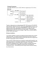
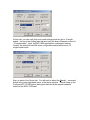
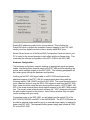
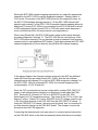
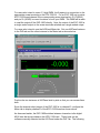
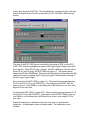
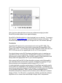
Temperature Measurements using the KPCI-3108 with
the EXP-1800
by
Andy Toth
Keithley Instruments Inc.
Introduction
Many applications require the use of data acquisition hardware to take high
channel count temperature measurements. The goal of this technical note is to
setup a KPCI data acquisition card using an external EXP multiplexing card. We
will be using a KPCI-3108 as the data acquisition hardware connected to an
EXP-1800 as the 16 channel multiplexing card. We will be reading in
temperature on single channel connected to a standard K type thermocouple.
While this type of temperature measurement solution for high channel count uses
a multiplexing card, Keithley offers several other temperature measuring
solutions for high channel count that may better fit your application or system
platform.
If your application requires less than 15 channels of temperature measurement,
Keithley offers an accessory called the STP-36CJC screw terminal panel with a
built-in CJC sensor for use with KPCI-3108 Series board. With other applications
limited to 31 channels, Keithley offers a ‘one card’ solution called the KPCI1801HC used with STA-1800HC screw terminal panel. The KPCI-1801HC
avoids having to use two EXP-1800s to achieve 31 temperature channels.
For applications that require thermocouples to be connected at a distance,
Keithley offers the M-1000 Series modules that can communicate on RS-232 or
RS-485. Finally, the 2700/2750/2701 data acquisition instrument offers the most
cost effective solution for channel counts in excess of 31 or applications that
demand measurement precision better than 0.5 deg C.
Setup
Prior to any set-up using the KPCI-3108 with an EXP-1800; users should have
read and became familiar with both the hardware manuals for the KPCI-3108
Series PCI Data Acquisition Board’s User’s manual (P/N 98080D) and the EXP1800 User’s Guide manual (P/N 92160A). This will ensure that users can followup on specific topics that will not be covered fully in this document.
The below block diagram shows a typical KPCI-3108 card with multiple EXP1800 set-up attached in a daisy chain fashion.
The above diagram does not show that each EXP-1800 requires a PG-408A DC
to DC converter attached to the EXP-1800 and the required power hook-up to the
PWR-5V power supply. Note, when using multiple EXP-1800s, they require an
additional power jumper cable called the CAB-PWR that enables bussing
additional power to each EXP-1800 from the same supply. This power jumper
cable has been omitted in the above diagram. Again, this is covered in detail in
the EXP-1800 Users manual.
Software Installation
The software installation requires the loading the Windows based driver software
called DriverLINX. The install procedure for DriverLINX will not be covered in
this document. Please reference the DriverLINX install sheet that is shipped with
the KPCI-3108 card as a source of reference.
Once, the KPCI-3108 card has been successfully installed with DriverLINX; it will
require a special driver configuration modification in the DriverLINX Configuration
Panel folder located on your desktop (Start > Programs > DriverLINX >
DriverLINX Configuration Panel). Select the Configure command button when
Device0 of the KPCI-3108 is highlighted (reverse blue) in the DriverLINX
Configuration Panel. This will bring up the Configure DriverLINX Device dialog
box (shown below).
At this time, you can verify that your board analog inputs are set to 16 singleended. Just go to the Analog Input tab and verify the board Channels: are set to
“16 single-ended”. Note, the EXP-1800 requires this configuration setting.
Usually, the default DriverLINX driver configuration setting will be set to 16
single-ended mode.
Now, go back to the Device tab. You will need to select the Special… command
button in the lower right-hand corner of the above window. This will bring up the
Configure KPCI-3108 Options dialog box that lists all the special hardware
feature of the KPCI-3108 card.
Enable EXP addressing radio button (shown above). This will allow the
DriverLINX driver to access the extended channel mapping of the EXP-1800
card(s) via a four digital lines control that is simply called MUX lines.
Select OK and close out of the DriverLINX Configuration Panel and reboot your
PC in order for the current changes to take effect with the software driver. This
concludes the software configuration of the KPCI-3108 for the EXP-1800.
Hardware Configuration
The hardware configuration requires hooking up appropriate signal and power
cables, interfacing screw terminal panel to the EXP-1800 and then adjusting the
proper switch settings located on the EXP-1800. The following paragraphs will
be a users guide through the hardware configuration.
Hooking up the EXP-1800 signal cable to a KPCI-3108 card requires the
additional support of the STP-3108-A1 screw terminal panel along with the
following cables, CAB-1284CC and the CACC-2000. The screw terminal panel is
just a transition device to map the KPCI-3108 signals to and from the EXP-1800.
Note, users should be using the most recent product revision #STP3108A1-10202C of the screw terminal panel which enables support for the EXP-1800 product
line. The correct screw terminal panel will have the “-02C” designator along with
the part number located on the product. Note, Earlier revisions may not report
correct readings with your setup.
Connecting power to the EXP-1800, you will need to set the switch S-9 of the
EXP-1800 to PWR-SEL and NOT to the DAS BOARD. The KPCI-3108 does not
provide for external power and the use of an external power supply is required to
power the EXP-1800. The required Keithley power supply part number is PWR5V for the EXP-1800.
Setting the EXP-1800 channel mapping requires that you select the appropriate
channel on the KPCI-3108 to map the expanded channels. Setting jumper to
CH0 on the J2 connector of the EXP-1800 allows for this mapping to occur on
the KPCI-3108 hardware through channel 0. All the EXP-1800 channels will
pass through channel 0 of the KPCI-3108. Expanded channel mapping allows for
additional (15 more) EXP-1800s to be connected to a KPCI-3108 card for a total
of 256 temperature signals (model 2700 or 2750 with switch cards becomes a
more cost effective choice for large channel count applications).
When using DriverLINX, the KPIC-3108 board’s single ended native channels
are always channels 0 through 15. The EXP-1800 can be used with any of the
KPCI-3108 native channels; it is not required to begin at channel 0 and increase
consecutively for each additional EXP added. Figure below shows the EXP-1800
channel assignments (for three boards) using DriverLINX channel mapping.
In the above diagram, the channel numbers assigned to the EXP are different
under ASO than they are under DriverLINX. Notice, that the first software
channel begins with channel 16 on the first EXP-1800 assigned to channel 0 of
the KPCI-3108. With the following EXP-1800s, the channel mapping will be
incremented by 16 (32, 48 and etc.).
Next, the CJC source selection can be configured for resident EXP-1800 CJC
sensor or an external sensor located on an accessory board called the FWAEXP. Setting the S-18 switch to FWA or to SOURCE on the EXP-1800
determines your CJC temperature source. The output of the CJC is a 10mV per
degree C output. When CJC is set to SOURCE, the CJC voltage output is sent
to the first logical channel of the EXP-1800 form the EXP-1800 CJC sensor. If
using the FWA-EXP CJC sensor, the user must physically ‘wire’ a connection to
a screw terminal channel on the FWA-EXP board. The example found in this
document used the FWA approach.
Connecting the thermocouple hook-ups are just to a screw terminal connection
on the FWA-EXP which is the field wire assembly board that allows for multiple
channel hook-up of thermocouples (the red wire of the thermocouple is always
the ground or channel lo connection). Note, a 10 K ‘bleed’ resistor to Low Side
Bias Return to GND A is provided via Switch 3 on the ‘DIP’ switch settings for
channels CH0-CH15 on the EXP-1800. Activating this setting will improve your
thermocouple input readings for thermocouple lead lengths that may be
subjected to static or EMI interference.
Other signal conditioning settings will not be covered in this document. The
EXP-1800 has variety of settings for Low Pass Filter (80 Hz), Open
Thermocouple Detect and Ground Selection. It is highly recommended that you
review this section on the Low Pass Filter in the EXP-1800 User’s manual. A Low
Pass Filter may help eliminate 60 Hz power line noise in some laboratory or
production floor environments.
Calibration
One of the most critical requirements in temperature measurement is the
calibration of your instrument or in this application your devices. The EXP-1800
has some very critical set points that need to be adjusted in order to make your
temperature readings correct and within product specification. The following
paragraphs will discuss the calibration procedure of an EXP-1800 while using the
KPCI-3108.
On the Keithley website www.keithley.com, there is an EXP-1800 calibration
software that is a useful tool in calibrating your EXP-1800. The software can be
found under Application Technical Support under Software Downloads using
“EXP-1800” as the keyword. Below is a screen shot of the calibration utility that
is a VB6 application with source code (available) to calibrate an EXP-1800 while
using a KPCI-3108 along with DriverLINX. This utility greatly simplifies the
calibration procedure and automates the process.
In the above calibration utility program, all one has to do is follow the above
procedure and adjust the R14 and R13 gain pots on the EXP-1800. See the
EXP-1800 hardware manual for gain pots location and description. If you prefer
to manually calibrate the card with out using the above application software. The
following paragraphs will discuss a manual approach to calibration by using the
AIOPanel as the software control (DIO tab) and read out (Meter tab) or a 5 ½
digit DMM (instrument) as an optional read out method.
During normal operation of an EXP-1800 with a KPCI-3108 Series board, the
digital output lines (OP0..OP4) of the KPCI-3108 board will be set for 'Enable
EXP addressing'. For calibration, change the configuration to ‘General purpose
Output’ use. In the DriverLINX Configuration Panel form (Start Menu > Programs
> DriverLINX> DriverLINX Configuration Panel) configure the KPCI-3108 digital
output lines (OP0...OP4) for general purpose Output as shown below. This will
allow us to have manual control of (OP..OP4) in the AIOPanel.
Additionally, the analog input channel configuration should always be set for 16
single-ended mode as shown below when using EXP-1800 accessories with
plug-in boards:
You will need to reboot to allow these configuration settings to take effect. Once
the software configuration has been changed, we will now need to adjust several
hardware potentiometers on the EXP-1800.
On the EXP-1800, both the RTO (R14) zero adjust and RTI (R13) zero adjust
potentiometers need to be adjusted to zero volts in order to get valid temperature
readings. This is accomplished by shorting CH0 HI to CH0 LO to GND A of the
FWA-EXP. Then adjusting potentiometer R14 to zero volts for a gain setting of 1
and R13 for zero volts for a gain setting of 50. This will require the use of the
Keithley AIO Panel to select the channel and the correct gain settings. Also, this
procedure will require a 5 ½ DMM or the use of another instance of the AIOPanel
Meter tab to validate the zero voltage output of the EXP shorted channel.
For users who intend to use a 5 ½ digit DMM, it will require to a connection to the
appropriate screw terminals on the STA-3108-A1. For an EXP-1800 set to native
KPCI-3108 board channel 0 the corresponding screw terminal pin 33 (CH00HI)
and pin 18 (AGND) is correct locations to hook your DMM. The DMM will be able
to read the output off the EXP-1800 directly. Note, the output of the EXP-1800 is
a single ended output so the screw terminals selected are a single ended output.
For users who intend to use the AIOPanel Meter tab. Set one AIOPanel instance
to the DIO tab and the other instance to the Meter tab as shown below:
Position the two instances of AIOPanel side by side so that you can access them
both.
Since the channel select jumper of the EXP-1800 is on channel 0, configure the
Meter tab to display channel 0 of the KPCI-3108 board as shown above.
As discussed earlier, the EXP-1800 switches between channels via the digital
MUX lines that are provided on the KPCI-3108 card. These lines can be
software manually selected via the AIO Panel under the DIO Tab. The following
screen shot shows the DIO Tab. The immediate four ‘grayed out’ bits to the right
under the Digital Output Panel corresponds to 0-15 on the EXP-1800 in binary
format.
The gain of the EXP-1800 can be controlled by the value of OP4 on the KPCI3108. OP4 is shown highlighted in green in the Digital Output Panel frame (fifth
bit to the left). When OP4 is logic 1 (green), the EXP-1800 gain of 50 is invoked.
When OP4 is logic 0 (gray), the EXP-1800 is at gain of 1. The screen above
shows the DIO tab of AIOPanel. Notice that the Digital Output Panel has the DIO
channel 0 turned on (default, bits 0-3 gray) and gain of 50 selected by having 4 th
bit set to logic 1(green light).
Now, command the EXP-1800 to a gain of 1. Place a shorting jumper between
CH 0 HI and CH 0 LO on the FWA-EXP. If the output from the EXP-1800 as
seen on your 5 ½ digit DMM or on the Meter tab of AIOPanel is not at zero volts,
adjust R14 for zero volts.
Command the EXP-1800 to a gain of 50. Place a shorting jumper between CH 0
HI and CH 0 LO on the FWA-EXP. If the output from the EXP-1800 as seen on
your DMM or on the Meter tab of AIOPanel is not at zero volts, adjust R13 for
zero volts.
Repeat the above two calibration steps one more time to minimize their
interaction. All adjustments have now been made. The calibration is now
finished.
Note, other channels of the EXP-1800 can be selected by manipulating the digital
lines (OP0..OP3) of the KPCI-3108. These four bits can generate 16 unique
binary codes corresponding to the 16 channels of the EXP-1800. The converted
numeric values correspond to the selected channels of the EXP-1800.
Remember to set the digital output lines (OP0..OP4) of the KPCI-3108 board
back to 'Enable EXP addressing' so that the DriverLINX software can
automatically control the DIO lines when accessing the channels/gain of the
EXP-1800. Earlier in the document we had shown the software configuration
procedure. If the KPCI-3108 is not configured for “Enable EXP Addressing”, the
MUX lines to the EXP-1800 will not be accessible by the KPCI-3108.
Once adjusted, EXP-1800 hardware calibration is now complete and you are
ready to take calibrated temperature readings. The card will report back
thermocouple readings with very little inherent voltage offset. If the EXP-1800, is
not correctly calibrated; the temperature data will be erroneous. Remember that
thermocouple voltages are on the magnitude of 1 mV and have a sensitivity of
approximately 10 micro volts per degree C. Even small voltage will influence
your thermocouple readings significantly. A shorted channel test can isolate
whether your system is inherently noisy or if there exists a considerable offset
calibration error with the EXP-1800.
For the KPCI-3108 card, it has its own KPCI-3108 Calibration Utility that guides
you through the software calibration process. This utility is self guided software
application which helps guide through calibration process. Note, not having both
the KPCI-3108 and the EXP-1800 in calibration may cause a substantial voltage
offsets on the level of several micro volts or more which may influence your
temperature readings. Always validate your system with a known voltage
standard prior to using the KPCI-3108 card with any thermocouples. A six digit
calibrated voltage source is highly recommended for a standard. Keithley offers
several types of instruments that can provide a reliable voltage standard for you
to calibrate your system.
Application
A typical application is high channel count measurement of temperature using a
standard PC as your mathematical processing device with a KPCI-3108 card or
alternatively converting an existing DAS-1800 (ISA) based EXP-1800 system
over to a KPCI-3108 (PCI) based EXP-1800 system. For new applications, the
KPCI-1801HC (PCI) product line offers up to 32 channels of temperature inputs
native to the board without the need of an external EXP-1800 card.
System Verification
System verification requires testing your hardware with some type of application
software. Unfortunately, the AIO Test Panel in DriverLINX will not suffice when it
comes to temperature conversion and reporting. However, Keithley offers a free
software plug-in called ExceLINX for Data Acquisition. This software package
works with MS Excel 97 or greater. It allows for quick verification of temperature
readings by capturing and converting data into an Excel spread sheet. This is an
ideal tool for users who do not need a custom software application that requires
advanced features. Note, ExceLINX for Data Acquisition has a sister package
called ExceLINX-1A for Instruments which offers the same flexibility for the
2700/2750 temperature measuring instrument line with built in added features.
Below is screen shot displaying the ExceLINX software working with the EXP1800. The image below shows the configuration of an ExceLINX’s AI Pace:
Clock Analog/Thermocouple input task.
Notice, that channel 16 is DriverLINX input channel for the FWA CJC and
channel 17 is input channel for the K type thermocouple.
The following screen shows the output data in an Excel graph of the K type
thermocouple located on software channel 17. As you can see, a simple test of
room temperature 23 +/- 0.5 C was attainable using this free software.
Note, the above data plot does not have any software averaging invoked.
ExceLINX provides means to use signal averaging.
ExceLINX for Data Acquistion is a free download from our web site. To acquire a
free copy go to www.keithley.com and select Products and go to Software. The
ExceLINX Help feature can guide you through the use of the software package.
Conclusion
The KPCI-3108 was found to communicate and control an EXP-1800. The
KPCI-3108 is an ideal board if one needs to convert an ISA based EXP-1800
system over to PCI. If you already own an EXP-1600 with a DAS-1600 card, the
KPCI-3108 can also be an upgrade path for ISA to PCI bus migration.
One should always review EXP hardware specifications prior to selecting any
new EXP board for your application. Keithley EXP models are not uniform in
performance or product options. One should be aware of these distinctions and
always select the appropriate EXP for your intended application.
After running the ExceLINX for Data Acquisition program under WindowsMe, it
was determined that we were able to acquire a temperature readings of K type
thermocouple at room temperature within a range of 23 +/- 0.5 C.
A similar application example was developed in Visual Basic and similar results
were found to be independent of the programming language. The benefits for a
proprietary programming language is that it allows for customization and flexibility
of your software application. Some ‘canned’ software packages like our
ExceLINX software have inherent built-in limitations due to Microsoft’s software
design of Excel. For VB and C++ programmers, Keithley provides the software
algorithm tools to convert raw thermocouple voltages over to temperature.
Check out the free T/C Library COM Object/DLL Interface for Thermocouple
Linearization package under Software Products at www.keithley.com