1
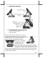
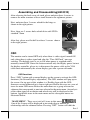
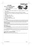
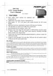
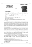
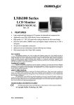
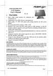
LM-2310/2210 LCD Monitor User’s Manual Rev. Original FCC NOTICE This equipment generates, uses, and can radiate radio frequency energy and, if not installed and used in accordance with the instructions manual, may cause interference to radio communications. It has been tested and found to comply with limits for a Class A digital device pursuant to subpart J of Part 15 of FCC Rules, which are designed to provide reasonable protection against interference when operated in a commercial environment. Operation of this equipment in a residential area is likely to cause interference in which case the user at his own expense will be required to take whatever measures to correct the interference. WARRANTY LIMITS Warranty will terminate automatically when the machine is opened by any person other than the authorized technicians. The user should consult his/her dealer for the problem happened. Warranty voids if the user does not follow the instructions in application of this merchandise. The manufacturer is by no means responsible for any damage or hazard caused by improper application. ABOUT THIS MANUAL This manual assists the user to utilize the Touch Monitor LM-2310/LM-2210. This product provides exquisite touch control capability over a stable and adjustable LCD monitor with minimal footprint. The manufacturer of the LM-2310/LM-2210 monitor heartily apologizes to the user for reserving the right to change or to modify this manual without notice due to the rapid and constant progress and improvement on science and technology. The user may always obtain the most up to date information through any of our web sites: http://www.posiflex.com, http://www.posiflex.com.tw, http://www.posiflexusa.com. Copyright Posiflex Technology, Inc. 2012 TRADE MARKS AND SERVICE MARKS P/N: 19610900010 POSIFLEX is a registered trademark of Posiflex Technology, Inc. Other brand and product names are trademarks and registered trademarks and service marks of their respective owners. I. FEATURES • LM-2310/LM-2210 is principally designed for Posiflex KS-series POS solutions • 10” LCD monitor with tilt adjustment for industrial and commercial use • High quality TFT LCD panel. • Easy maintenance structure allowing easy cleaning • Super VGA monitor resolution up to 800 x 600 pixels • Support power supply through LCD cable from Posiflex Terminal to operate without power adaptor Part 1 II. PARTS IDENTIFICATION A. FRONT VIEW (LM-2210/LM-2310) Main Unit Display Screen Power LED Stand B. REAR VIEW (LM-2210/LM-2310) Main Unit Hinge Base Stand Cable Exit Joint Bracket C. SIDE VIEW (LM-2310) VGA Connector and DC jack Control button area OSD button NXT button “+” button “-“ button Power switch Part 2 C. SIDE VIEW (LM-2210) Control button area VGA Connector and DC jack. OSD button NXT button “+” button “-“ button Power switch D. POWEPOWER LED INDICATION • Green: standby (no signal) • Blue: operating Before routing the cable, please release the hooks CABLE ROUTING IN BASE (LM-2210) Of stand’s back cover as arrowed in the right picture. For cable routing in mini slim base, please refer to the picture at left. There are 2 cable tie holder slits on the metal bracket for the trunk as arrowed in the picture. Hold all the external cables with a cable tie through the right cable tie holder slit and leave the cables to the left holder slit. Have all cables to pass through the oval hole on the trunk to come out of the front side of trunk. Connect all the cable ends to main unit. Be sure not to damage any cable during this operation. Part 3 VESA MOUNT After releasing the stand’s back cover, please unfasten these two screws to remove the main structure of base stand which arrowed in the right picture. After that, please use flat drill to release the hinge cover from the arrowed side as show in the right picture. Next, unfasten these four screws which fix the hinge as shown in the middle right picture and remove the hinge. Now, there are four screws holes which fit in with VESA standard 75mm and use another four bind head screws which attached in the packing kit to fasten on the VESA arm or bracket. CABLE ROUTING IN BASE (LM-2310) Before routing the cable, please release the hooks of back cover of stand as arrowed in the right picture. For cable routing in mini slim base, please refer to the picture below. There are 3 cable tie holder slits on the metal bracket for the trunk as arrowed in the picture. Hold all the external cables with a cable tie through the right cable tie holder slit and leave the cables to the left holder slit. Have all cables pass through the oval hole on the trunk to come out of the front side of trunk. Connect all the cable ends to main unit. Be sure not to damage any cable during this operation. Part 4 Assembling and Disassembling(LM-2310) After releasing the back cover of stand, please unfasten these 4 screws to remove the main structure of base stand shown in the rightmost picture. Next, unfasten these 3 screws which fix the hinge as shown in the right picture. Now, there are 3 screws holes which fit in with VESA standard 75mm After that, please use flat drill to release 3 screws shown in the right picture. OSD The monitor can be turned OFF only when there is video signal; turned ON only when there is video signal and after the “Turn Off Panel” message vanishes. The default status is set to ON when power is supplied unless manually turned OFF. Since this button controls only the display power but not the display controller, please try to disconnect the power cable or the VGA cable once unfortunately the screen display goes into a power-off mode. OSD functions Press “OSD” button with a normal display on the screen to activate the OSD functions (On Screen Display adjustment). The OSD window will pop up on the screen. On top part of this window is a Posiflex logo with the OSD firmware version indicated to its lower right part. Below this area are a row of icons for main OSD menu. Below the main menu are a group of icons for submenu that corresponds to one icon selected in the main menu. An analysis of the video signal on resolution and refresh rate will be displayed at the bottom. Applicable icons in the main menu and its subsequent menus are illustrated below. “MAIN MENU”: There are a total of 5 icons in this menu: One of the 5 icons will be displayed in inverted color to indicate its relationship with the submenu below. Pressing “NXT” button will shift the Part 5 selected icon one by one from left to right and then wrap around to the leftmost part. Press “OSD” button to enter the selected sub menu. If there is no button for OSD setting, is pressed within a period of time (about 5 seconds to 1 minute as programmed) the OSD window will disappear with all the adjusted parameters saved. Items in sub menu are illustrated below. “BRIGHTNESS / CONTRAST ADJUST SUBMENU”: There are 3 icons in this submenu: Press “OSD” button to select item or return to main menu. Press “NXT” button to select among brightness, contrast and exit. “BRIGHTNESS ADJUST”: When this item is selected, there will be only the brightness icon with an adjustment indication bar under it between the main menu area and the video signal mode. Press “+” button to increase brightness. Press “-” to decrease. Press “OSD” button to save the current setting and return to “Brightness/Contrast submenu”. “CONTRAST ADJUST”: When this item is selected, there will be only the contrast icon with an adjustment indication bar under it between the main menu area and the video signal mode. Press “+” button to increase contrast. Press “-” to decrease. Press “OSD” button to save the current setting and return to “Brightness/Contrast submenu”. “EXIT”: Return to “Main menu”. “COLOR ADJUST SUBMENU”: There are 4 icons in this submenu: Press “OSD” button to select item or return to main menu. Press “NXT” button to select among auto color adjust, auto RGB reset, Color balance adjust and exit. “AUTO COLOR ADJUST”: Upon an “OSD” button press on this icon the monitor will perform an automatic color adjustment and exits the OSD window leaving 2 icons below at center of the screen. Press “NXT” button to switch the selection. Press “OSD” button to make the choice. “ACCEPT”: Accept the adjustment setting. “REJECT”: Decline the adjustment setting and return to previous setting. “AUTO RGB RESET”: Upon an “OSD” button press on this icon the monitor will perform an automatic RGB reset and exits the OSD window leaving 2 icons below at the center of the screen. Press “NXT” button to switch the selection. Press “OSD” button to make the choice. “ACCEPT”: Accept the reset result. “REJECT”: Decline the reset and return to previous setting. “COLOR BALANCE ADJUST”: When this item is selected, there will be 7 icons in this item between Part 6 main menu area and the video signal mode. Press “OSD” button to select an item or return to color adjust submenu. Press “NXT” button to select among separate color adjustment, 4200K, 5000K, 6500K, 7500K, 9300K and exit. “SEPARATE COLOR ADJUST”: When this item is selected, there will be 3 adjustment indication bars between the main menu area and the video signal mode. Press “NXT” button to select among the 3 colors Red, Green and Blue respectively. Press “+” button to intensify that color. Press “-” to reduce. Press “OSD” button to save the current setting and return to “Color balance adjust submenu”. “4200K”: Pressing “OSD” button on this icon will set the color balance to a color temperature of 4200 degrees Kelvin. “5000K”: Pressing “OSD” button on this icon will set the color balance to a color temperature of 5000 degrees Kelvin. “6500K”: Pressing “OSD” button on this icon will set the color balance to a color temperature of 6500 degrees Kelvin. “7500K”: Pressing “OSD” button on this icon will set the color balance to a color temperature of 7500 degrees Kelvin. “9300K”: Pressing “OSD” button on this icon will set the color balance to a color temperature of 9300 degrees Kelvin. “EXIT”: Return to “Color adjust submenu”. “EXIT”: Return to “Main menu”. “GEOMETRY ADJUST SUBMENU”: There are 6 icons in this submenu: Press “OSD” button to select item or return to main menu. Press “NXT” button to select among auto geometry adjustment, horizontal size, phase, horizontal position, vertical position and exit. “AUTO GEOMETRY ADJUST”: Upon an “OSD” button press on this icon the monitor will perform an automatic geometry adjustment and exits the OSD window leaving 2 icons below at the center of the screen. Press “NXT” button to switch the selection. Press “OSD” button to make the choice. “ACCEPT”: Accept the adjustment setting. “REJECT”: Decline the adjustment setting and return to previous setting. “HORIZONTAL SIZE”: When this item is selected, there will be only the horizontal size icon with an adjustment indication bar under it between the main menu area and the video signal mode. Press “+” button to increase horizontal size. Press “-” to decrease. Press “OSD” button to save the current setting and return to “Geometry adjust submenu”. “PHASE”: When this item is selected, there will be only the Part 7 phase adjustment icon with an adjustment indication bar under it between the main menu area and the video signal mode. Press “+” or “” button to adjust the pixel synchronization phase for the best picture display. Press “OSD” button to save the current setting and return to “Geometry adjust submenu”. “HORIZONTAL POSITION”: When this item is selected, there will be only the horizontal position icon with an adjustment indication bar under it between the main menu area and the video signal mode. Press “+” or “-” button to shift the screen display to the right or left. Press “OSD” button to save the current setting and return to “Geometry adjust submenu”. “VERTICAL POSITION”: When this item is selected, there will be only the vertical position icon with an adjustment indication bar under it between the main menu area and the video signal mode. Press “+” button to shift up the screen display. Press “-” to shift down. Press “OSD” button to save the current setting and return to “Geometry adjust submenu”. “EXIT”: Return to “Main menu”. “TOOLS SUBMENU”: When this item is selected, there are 5 icons in this submenu: Press “OSD” button to select item or return to main menu. Press “NXT” button to select among OSD submenu, reset to default, phase, smoothness / sharpness adjust, mode select and exit. “OSD SUBMENU”: When this item is selected, there are 4 icons in this submenu: Press “OSD” button to select item or return to main menu. Press “NXT” button to select among OSD time, OSD horizontal position, OSD vertical position and exit. “OSD TIME”: When this item is selected, there will be only the OSD time icon with an adjustment indication bar under it between the main menu area and the video signal mode. Press “+” or “-” button to adjust the waiting time for OSD operation before OSD termination between 5 to 60 seconds. Default value is 30 seconds. Press “OSD” button to save the current setting and return to “OSD submenu”. “OSD HORIZONTAL POSITION”: When this item is selected, there will be only the vertical position icon with an adjustment indication bar under it between the main menu area and the video signal mode. Press “+” button to shift OSD window right. Press “-” to shift left. Press “OSD” button to save the current setting and return to “OSD submenu”. “OSD VERTICAL POSITION”: When this item is selected, there will be only the vertical position icon with an adjustment indication bar under it between the main menu area Part 8 and the video signal mode. Press “+” button to move OSD window downward. Press “-” to go upward. Press “OSD” button to save the current setting and return to “OSD submenu”. “EXIT”: Return to “Tools submenu”. “RESET TO DEFAULT”: Pressing “OSD” button on this icon will set all parameters back to the status when the monitor is factory installed. “SMOOTHNESS / SHARPNESS ADJUST”: When this item is selected, there will be only the smoothness / sharpness adjustment icon with an adjustment indication bar under it between the main menu area and the video signal mode. Press “+” button to increase smoothness of display (decrease sharpness). Press “-” to go the other way. Press “OSD” button to save the current setting and return to “OSD submenu”. “MODE SELECT”: Pressing “OSD” button on this icon will have no effect at all if the display mode is not one of the confusing modes. The confusing modes here mean 640 x 400 or 720 x 400 in display resolution as both modes have refresh rate of 70Hz, horizontal frequency of 37.9KHz and pixel frequency of 31.5MHz making it impossible for automatic select. These modes are not used in normal Windows display. “EXIT”: Return to “Main menu”. “EXIT”: Exit OSD setup with all adjustment saved. SUPPORTED DISPLAY MODES For video signals beyond the supported display modes, there will be a message “Out Of Range” on the middle of screen. Maximum supported color depth is 24 bits or 16.7M colors. Supported display modes are illustrated in the table: Horizontal Display Resolution Refresh Rate (Hz) Frequency (KHz) 640*400 70 37.9 60 31.5 640*480 72 37.9 75 37.5 720*400 70 37.9 56 35.1 60 37.9 800*600 72 48.1 75 46.9 警告使用者 T31454 這是甲類的資訊產品,在居住的環 境中使用時,可能會造成射頻干 擾,在這種情況下,使用者會被要 求採取某些適當的對策。 警告 本電池如果更換不正確會有爆炸的危險 請依製造商說明書處理用過之電池 Part 9