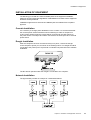
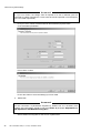
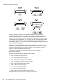
1
NAVINAVI-CONNING 3000
(VERSION 4.01.00)
INSTALLATION GUIDE
© Transas Ltd. June, 2005
© Transas Ltd. 2005
All rights reserved. The information contained herein is proprietary to Transas Ltd.
and shall not be duplicated in whole or in part.
The technical details contained in this manual are the best that are available at the date of issue
but are subject to change without notice. Transas Ltd. pursues the policy of continuous development.
This may lead to the product described in this manual being different from the product delivered after its publication.
Microsoft and Windows are registered trademarks of Microsoft Corporation.
The names of actual companies and products mentioned herein may be the trademarks of their respective owners.
This document contains:
Preamble
This chapter contains general information on the work with the manual.
Chapter 1
NC Technical Specification.
This chapter gives full technical and operational specifications
for the Navi-Conning 3000.
Chapter 2
289
Questionnaire.
Provided in this annex is an example of completing
the Questionnaire table.
Annex E
233
Additional Information on Sensor Connections.
This annex contains more detailed information on computer’s serial
ports and RS 232 standard.
Annex D
157
OS Installations.
This annex describes installation of OS (Windows 2000, Windows NT 4.0)
both for Transas dedicated computers and for standard PC’s.
Annex C
141
Additional Settings of Navi-Conning.
This annex provides a description of the NС program’s additional
settings and of NMEA editor.
Annex B
125
Troubleshooting.
This chapter explains procedures for troubleshooting and fault reporting.
Annex A
61
Maintenance.
This chapter describes procedures for typical cases of service work.
Chapter 4
11
Installation and Registration of the NC.
This chapter provides notes on installation and adjustment of the
NC 3000 program, procedures for system registration and back-up.
Chapter 3
3
299
Transas Conning Box Testing Method.
This annex describes operation of Transas Conning Box Testing Utility.
305
NAVI-CONNING 3000 (v. 4.01.00). Installation Guide.
1
PREAMBLE
This chapter contains general information on the work
with the manual.
Copyright Transas Ltd., 2005
Warnings and Cautions
WARNINGS AND CAUTIONS
This document is intended for use by service engineers only, providing installation or
service for Transas Ltd. navigation systems, and holding Transas Ltd. Certificates for
aforementioned works.
WARNING!
Lethal Voltage Hazard!
Inside the equipment and in the cables lethal voltage hazard is present. When
access covers are removed, lethal voltages may be exposed. Some capacitors used
in the equipment take several minutes to discharge their stored voltages after the
switching OFF, this is a lethal voltage hazard. Always set the supply switch-fuse to
OFF and remove the fuses, before removing the access covers of the equipment.
Cables must be connected to the power supplies only provided with grounding.
Cables must not have damaged insulation and must exclude contact with parts
conducting current.
WARNING!
Health Hazard!
When cleaning the inside of the equipment, take care not to inhale dust. The dust is
a temporary health hazard, depending on individual allergies.
Units radiate heat and must be installed in such way that free air circulation is ensured.
It is necessary to strictly follow the requirements set forth in the operation manuals
for computers and system’s peripheral devices.
CAUTION!
Electrostatic Sensitive Devices (ESSDs)!
The equipment may contain ESSDs. Take care not to damage these devices
by discharge of electrostatic voltages.
Preamble.
5
List of Documentation on Navi-Conning 3000 Product
LIST OF DOCUMENTATION ON NAVI-CONNING 3000 PRODUCT
Navi-Conning 3000 (version 4.01.00). Installation Guide.
Navi-Conning 3000 (version 4.01.00). User Manual.
Navi-Conning 3000 (version 4.01.00). Alarm Station Functionality Description.
Navi-Conning 3000 (version 4.01.00). Data Recording System Functionality
Description.
ABBREVIATIONS IN USE
6
•
A – Ampere;
•
AC – Alternating Current;
•
ADC – Analog-to-Digital Converter;
•
ASCII – American Standard Code for Information Interchange;
•
CB – Conning Box;
•
CIB – Conning Interface Box;
•
COG – Course Over Ground;
•
DC – Direct Current;
•
DIN – DIN connector;
•
Hz – Hertz;
•
IEC – International Electrotechnical Commission;
•
I/O – Input/Output;
•
IPX/SPX – Internet Packet exchange/Sequenced Packet exchange;
•
IRQ – Interrupt ReQuest;
•
LAN – Local Area Network;
•
MMD – Maritime Multi Displays;
•
MNS – Marine Navigation Systems;
•
NC 3000 – Navi-Conning;
•
NMEA – National Marine Electronics Association;
•
NS – Navi-Sailor;
•
PC – Personal Computer;
•
PCI – Peripheral Component Interconnect;
•
ROT – Rate Of Turn;
•
RPM – Revolution Per Minute;
•
RS – Recommended Standard (232);
•
Sec – Second;
•
SOG – Speed Over Ground;
•
TCB – Transas Conning Box;
•
TFT – Thin Film Transistor;
NAVI-CONNING 3000 (v. 4.01.00). Installation Guide.
Printing House Conventions
•
UPS – Uninterruptible Power Supply;
•
UTC – Universal Time Coordinated;
•
V – Volt;
•
W – Watt;
•
WP – Way Point;
•
XTE – Cross Track Error.
PRINTING HOUSE CONVENTIONS
Sample of an entry
Comments on the use
Chapter 3
To highlight, in a printed document, names of this document
sections
Date and Time
To highlight, in a printed document, names of program
functions mentioned in this document
TrkCvt.txt
To highlight, in a printed document, messages, commands,
files and other information supplied by the OS
C:\Transas\Navi-Conning
To highlight, in a printed document, a path to the menu,
function, file, etc.
<Enter>
To highlight, in a printed document, names of keyboard keys
“Next”
To highlight, in a printed document, names of a window,
page, option, button, etc.
TOOLS
To highlight, in a printed document, menu items mentioned
in this document
SOFTWARE LICENSE AGREEMENT
WARNING!
This computer program is only a navigational aid and is not a substitute for any navigational
equipment that may be required under applicable regulations or law.
This computer program is not fault-tolerant and is not designed, manufactured or intended for
use as control equipment in hazardous environments in which the failure of the computer
program could lead directly or indirectly to death, personal injury or severe physical or
environmental damage.
Software License Agreement. Transas Ltd. (“Transas”) agrees to grant (subject to Customer’s
registration of the computer program) and Customer agrees to accept on the following terms and
conditions, a non-transferable non-exclusive license to use the Transas computer program
(“the Licensed Program”) delivered with this Agreement. This Agreement confers no ownership or
title in the Licensed Program and confers no rights whatsoever in any associated source code or in
any other intellectual property of Transas or its suppliers. Title, ownership and intellectual property
rights to this Licensed Program shall remain in Transas and its suppliers. The Licensed Program
is protected under copyright law and international treaties.
Period of License. The license commences on the date Customer breaks the seal of
navigation product CD case and is effective until terminated.
License. This license authorises Customer to use the Licensed Program in a machine-readable form
on one computer system (hereinafter referred to as “System”) as provided in the Licensed Program
user manuals. The Licensed Program may be physically (but not electronically) removed from one
System and transferred to another System provided always the Licensed Program is only used on
one System at a time unless a separate license fee has been paid for each additional System.
Preamble.
7
Software License Agreement
This Agreement and any of the licenses, programs or materials to which it applies may not be
assigned, sub-licensed, hired, lent or otherwise transferred by Customer. Customer may not modify,
translate, disassemble, decompile or reverse-engineer the licensed program or any copy, in whole
or in part, unless Transas prior written consent is obtained or not required by law.
Permission to Copy Licensed Program. Customer shall not copy in whole or in part any Licensed
Program documentation, which is provided by Transas. Any Licensed Program which is provided
by Transas in machine readable form may be copied in whole or in part in sufficient number for use
by Customer with the System for back-up purposes and for archival purposes, provided however,
that no more than two (2) copies will be in existence under any license at any one time. Any and all
such copies are subject to the terms and conditions of this license and must bear the copyright and
other proprietary notices on or in the original media as well as any restricted rights legends or
warnings on or in the original data.
Termination. Transas may terminate this Agreement upon written notice in the event that
Customer fails to comply with this Agreement. Immediately upon termination of the license,
Customer will destroy or return to Transas the original and all copies of the Licensed Program.
Limited Warranty. Transas makes no warranties with respect to the Licensed Program other than
to guarantee the original disk against faulty materials or workmanship for ninety (90) days from the
date on which Customer registers the product, provided registration is made within fourteen days
of receiving the product. Transas’ entire liability and Customer’s exclusive remedy shall be
replacement of the Licensed Program if the media on whom the Licensed Program is furnished
proves to be defective. This warranty is void if the media defect has resulted from accident, abuse
or misapplication. The aforementioned warranty is in lieu of all other representations, warranties,
conditions and guarantees of any kind, express or implied, including but not limited to the implied
warranties of satisfactory quality, fitness for a particular purpose and/or noninfringment of third
party rights.
Limitation of Liability. To the maximum extent permitted by applicable law, in no event shall
Transas or its suppliers be liable for any special, incidental, indirect, or consequential damages
whatsoever (including, without limitation, damages for loss of business profits, business
interruption, loss of business information, or any other pecuniary loss) arising out of the use of or
inability to use the Licensed Program or the provision or failure to provide support services even if
Transas has been advised of the possibility of such damages. In any case, Transas’ entire liability
under any provision of this Agreement shall be limited to the amount actually paid by Customer for
the Licensed Program, provided, however, if Customer has entered into a Transas maintenance
services agreement, Transas entire liability regarding maintenance services shall be governed by
the terms of that agreement.
Limitation of Damages. Under no circumstance shall Transas be liable to Customer or to third
parties for loss of profit or direct or indirect loss or damage whether special, consequential or
otherwise, and howsoever arising, including, but not limited to, loss of profit or loss or damage
arising from breakdown or failure of the Licensed Program.
General. This Agreement does not affect or prejudice the statutory rights of a Customer acquiring
the Licensed Program otherwise than in the course of a business. If any of the above provisions or
portions thereof are invalid under any applicable law, they are to that extent only deemed to be
omitted. This Agreement constitutes the entire agreement between the parties relating to the
licensing of the Licensed Program. No variation or amendment or addition to the terms and
conditions of this Agreement shall be effective unless the prior agreement of Transas in writing shall
have been obtained. Any third party supplier of software contained in the Licensed Program or
included in the Transas Maintenance Service may protect its rights in the Licensed Program against
violations of this Agreement, including any infringement of the third party supplier’s copyrights.
The governing law of this Agreement shall be that of England.
8
NAVI-CONNING 3000 (v. 4.01.00). Installation Guide.
Software License Agreement
Maintenance Services. Transas may provide Customer with certain maintenance services
(“Maintenance Services”). Maintenance Services are governed by the Transas policies
described in the Licensed Program user’s manual and/or in “online” documentation. Any
supplement software code provided to Customer, as part of Maintenance Services shall be
considered as part of the Licensed Program and subject to the terms and conditions of this
Agreement. With respect to technical information Customer provides to Transas as part of the
Maintenance Services, Transas may use such information for its business purpose, including
for product updates and development. Transas will use its best efforts to not utilise such
technical information in a form that personally identifies Customer.
Preamble.
9
CHAPTER 1
NC Technical Specification
This chapter gives full technical and operational
specifications for the Navi-Conning 3000.
Copyright Transas Ltd., 2005
This chapter contains:
Reference Table .......................................................................................................15
Software Technical Specification...........................................................................16
General...............................................................................................................16
Purpose of Navi-Conning Program ..........................................................16
Software and Hardware Requirements....................................................16
Reception/Processing and Output of Data from/to External Devices.....................17
Data Exchange Channels ........................................................................17
Interfaces .................................................................................................17
NC – NS Possible Configuration..............................................................18
NMEA Format Editor ..........................................................................................19
Purpose of the Editor ...............................................................................19
Editor Capabilities and Limitations...........................................................19
Recording Functionality......................................................................................20
Predictor (For Trial Purposes Only) ...................................................................20
Extendable Measurement Units Database ........................................................21
Three Screen Views for Input Parameters Display ............................................22
General ....................................................................................................22
“Sea” Screen View ...................................................................................23
“Narrow” Screen View..............................................................................23
“Mooring” Screen View ............................................................................24
“Alarms” Screen View ..............................................................................24
Alternative Screen Views for Input Parameters Display ....................................25
Alternative Screen View No. 1 .................................................................25
Alternative Screen View No. 2 .................................................................26
Software Options................................................................................................26
General ....................................................................................................26
Playback Functionality .............................................................................26
Alarm Station Functionality ......................................................................27
Data Recording System (DRS) ................................................................27
Customization of Basic Configuration ......................................................28
Hardware Technical Specification .........................................................................30
Navi-Conning Carton..........................................................................................30
General ....................................................................................................30
Set of Navi-Conning Manuals ..................................................................30
Protection Key (Dongle) ...........................................................................30
License.....................................................................................................31
Marine Navigation Systems CD ...............................................................31
Conning Box.......................................................................................................33
General ....................................................................................................33
WAGO CB................................................................................................33
Transas Ltd. CB .......................................................................................34
Computers..........................................................................................................36
General ....................................................................................................36
RS3 Basic ................................................................................................36
RS3 EC ....................................................................................................36
RS3 Dimensions ......................................................................................37
RS4 Basic ................................................................................................38
RS4 Dimensions ......................................................................................39
Optional Components ..............................................................................39
Chapter 1. NC Technical Specification.
13
Transas Dedicated Keyboard ES4 .................................................................... 40
Functional Description ............................................................................. 40
Keyboard Legend .................................................................................... 40
Technical Data......................................................................................... 41
Rear Panel............................................................................................... 41
Transas Monitors ............................................................................................... 48
General .................................................................................................... 48
Features .................................................................................................. 48
Product Specifications ............................................................................. 48
Approvals................................................................................................. 53
Uninterruptible Power Supply (UPS) ................................................................. 53
General .................................................................................................... 53
UPS APC Smart ...................................................................................... 53
UPS Powerware 5115 ............................................................................. 54
UPS Powerware 9120 ............................................................................. 54
UPS MGE Extreme 1500 C Rack Marine ............................................... 55
Transas Consoles.............................................................................................. 56
General .................................................................................................... 56
Transas Console Version 5.2 .................................................................. 56
Console Reduction Frame 23"/20" TFT .................................................. 58
Console Reduction Frame 23"/19" TFT .................................................. 58
Opto Isolated Converters................................................................................... 59
14
NAVI-CONNING 3000 (v. 4.01.00). Installation Guide.
Reference Table
REFERENCE TABLE
Scope of supply
Navi-Conning
Software capabilities
Basic configuration
• Digital/Analog Data Input
Yes
• NMEA output
Yes
• NMEA Format Editor
Yes
• Predictor
Yes
• Recording Functionality
Yes
• Extendable Measurement Units Database
Yes
• Three Standard Screen Views for Parameters Display
Yes
• Playback Functionality
Option
• Custom made Screen Views (2-4 weeks depending on order complexity)
Option
• Alarm Station Functionality
Option
• Data Recording System (DRS) Functionality
Option
• DRS Playback Utility
• Development of New Interfaces
Option
Hardware/accessories
Conning Box by WAGO
• 750-314 “Main Module”
Option
• 750-600 “End Module”
Option
• 750-403 “Digital Input Module”
Option
• 750-476 “2 Channel analog Input Module (-10/10 V)”
Option
• 750-513 “Digital Output Module”
Option
• 750-454 “2 Channel analog Input Module (4-20 mA)”
Option
• 750-468 “4 Channel analog Input Module (0-10 V)”
Option
Computers
• RS3 Basic Data Processing Unit
Option
• RS3 EC Data Processing Unit
Option
• RS4 Basic Data Processing Unit
Option
Uninterruptible Power Supply (UPS)
• UPS SMART 700 230V
Option
• UPS Smart 19” 700 230V
Option
Monitors
• 19” TFT Hatteland JH 19 T04 MMD E1 (1280 x 1024) Monitor
Option
• 20” TFT, Hatteland JH 20 T03 MMD E1 (1280 x 1024) Monitor
Option
• 20” TFT, Hatteland JH 20 T04 MMD E1 (1280 x 1024) Monitor
Option
• 23” TFT Hatteland JH 23 T01 MMD E1 (1280 x 1024) Monitor
Option
Input Units
• ES4 Dedicated Keyboard
Option
• Windows Keyboard (English)
Option
Consoles
• Transas Console Version 5.2
Option
• Console Reduction Frame 23 “TFT/19” TFT. This unit is an optional
component for Console Version 5.2
Option
• Console Reduction Frame 23 “TFT/20” TFT. This unit is an optional
component for Console Version 5.2
Option
• Desktop Console Version 5.0
Option
Chapter 1. NC Technical Specification.
15
Software Technical Specification
Scope of supply
Navi-Conning
Opto Isolated Converter
• DB-9 (without cable)
Option
• DB-25 (without cable)
Option
• Current Loop
Option
Navi-Conning Carton
Yes
SOFTWARE TECHNICAL SPECIFICATION
General
Purpose of Navi-Conning Program
Navi-Conning (NC) program is intended for the processing and recording of
parameters supplied via different channels from external sources of information.
The received and processed parameters are used further for the following purposes:
•
Display on the NC screen;
•
Data conversion from one digital/analog format (Input) to another (Output).
Note: Output of analog data converted to NMEA is supported by Transas Conning
Box only.
The NC program is capable of supporting the processing of any parameters
supplied both, in ASCII code and in the binary form. The program is structured
so that it allows addition of any interface ordered by the Customer
(see paragraph Software New Options).
Software and Hardware Requirements
If the customer does not use Transas Marine hardware facilities, it will be necessary
to select hardware and software meeting the following minimum requirements:
•
Hardware:
– CPU: Pentium-III 700 MHz or higher;
– RAM 96 Mb minimum (256 Mb recommended);
– VRAM” 16 Mb;
– 3,5” fl-drive;
– SVGA;
16
NAVI-CONNING 3000 (v. 4.01.00). Installation Guide.
Software Technical Specification
– HDD: 2,0 Gb free disk space (120 Gb recommended);
– CD drive;
– 3.5” FDD (recommended);
– Parallel Port;
– Net card 100Mb Fast Etherlink, 100Mb Fast Etherlink Hub, ТР5 category cables.
•
Software:
– Windows 2000 Professional Service Pack 3;
– Windows NT 4.0 English version, Service Pack 5 (not under warranty);
– Windows XP Professional (not under warranty).
ATTENTION!
It is not advisable to use the computer for other purposes. Other programs loaded
in the RAM may have adverse effect on the system operation.
For hardware and software requirements for Data Recording System see
NAVI-CONNING 3000 (V. 4.01.00). DATA RECORDING SYSTEM FUNCTIONALITY
DESCRIPTION document.
Reception/Processing and Output of Data from/to External Devices
Data Exchange Channels
The NC uses three types of channels for the data exchange with external devices:
•
Serial (RS232-type) ports;
•
Virtual ports, where the NC and other programs operate on the same computer.
In this case, the NC assumes this information as supplied from the serial port;
•
Network. When operating via the network card, the NC can use parameters
networked by Navi-Sailor program. Exchange of information with the NS2400
and NS3000 ver.3.xx is provided via IPX/SPX protocol, with NS3000 ver.4.xx
via TCP/IP protocol.
Interfaces
NC program supports the following data exchange formats and their versions:
•
NMEA. Operation in accordance with this protocol is via serial RS232-type
and virtual ports. The NC allows operation with the following versions of NMEA
sentences:
– NMEA 0183 version 3.01 (Jan 2002);
– NMEA 0183 version 3.0 (Jul 2000)/IEC 61162-1 edition 2 (Jul 2000);
– NMEA 0183 version 2.1 (Oct 1995)/IEC 61162-1 edition 1 (Nov 1995).
For the user convenience sake, databases of sentences from each version are
generated. They allow one of the sentences to be selected for the further use,
or the sentences to be used as the basis for the formation of sentences the user
requires, by using the Sentence Editor.
•
Transas Conning Box (analog/digital) converter;
•
WAGO (analog/digital) converter;
•
Binary TRANSAS proprietary format for an interface with NS electronic chart
system via LAN.
Chapter 1. NC Technical Specification.
17
Software Technical Specification
NC – NS Possible Configuration
In case of the NC network operation, it can receive parameters from Navi-Sailor
electronic chart system.
ATTENTION!
For the NS operation in the network configuration, the network operation option
should be permitted by the NS license.
Data exchange uses IPX/SPX protocol. Provided below are the available network
configurations with their features and disadvantages:
•
NC “Slave” – NS “Master”;
•
NC “Standalone” with NS “Master” – NS “Slave”.
Note: There exist the following restrictions for this configuration:
• This configuration does not provide “Predictor” functionality or the
graphic display of a route on Navi-Conning Screen Views;
• Order of the product installation: NC 3000, then NS3000;
• If the system is used simultaneously with the NS2400 or NS3000 v.3.xx,
the color palettes are switched separately for each application.
•
18
NS “Master” – NC “Slave” with NS “Standalone” – NS “Slave”.
NAVI-CONNING 3000 (v. 4.01.00). Installation Guide.
Software Technical Specification
Note: In this configuration, reception of parameters networked by “Master” station
will not be available for the NS “Standalone”.
NMEA Format Editor
Purpose of the Editor
The principle underlying the NC program implies extraction of parameters from the
incoming data stream and their further processing. With the use of NMEA interface,
information is supplied to the NC in the form of sentences constructed in accordance
with the international standards. Stored in the NC database are the most commonly
used sentences of various NMEA standard versions. However, any NMEA sentences
can be processed by means of the NC and added to the custom made sentence
database. This is what the Sentence Editor is intended for.
The use of Sentence Editor allows:
•
To supplement the database with a new sentence to extract the parameters
contained in this sentence;
•
Use the of available parameters for creating a sentence that can be output
to any external user via Serial or Virtual ports.
Editor Capabilities and Limitations
The processing of NMEA/IEC sentences is based on the principles built into NMEA
standard, although the program’s versatility allows deviations from the observance
of the standard rules and processing of sentences not stipulated by the standard.
The sentences processed by NC program are required to fulfil the following NMEA
standard rules:
•
Sentences consist of characters represented in ASCII code;
•
Each type of sentence consists of a fixed number of fields (otherwise refer
to “Development of a New Interfaces” software option);
•
There is a definite order of parameters in the sentence.
NC program allows the following deviations from the standard to be used:
•
Sentence may have any sentence start symbol (!aaccc,c---c*hh<CR><LF>);
•
Sentence may have any source identifier (TALKER), but always 2 symbols
($bbccc,c---c*hh<CR><LF>);
•
Sentence may have any sentence type identifier (NAME), but always 3 symbols
($aaddd,c---c,*hh<CR><LF>).
Chapter 1. NC Technical Specification.
19
Software Technical Specification
The NMEA format editor has the following limitations:
•
All parameters are always independent of each other (NMEA sentences such
as XDR, etc.);
•
Sentences containing the parameters are always independent of each other –
NMEA sentences such as WPL, GSA, etc. (otherwise refer to “Development
of a New Interfaces” software option);
•
There is no capability to transmit sentences with same names to Output via one
or more channels);
•
Sentences containing additional parameter characteristics (e.g. True/Magnetic,
Theoretical/Relative, N/S, E/W, etc.) cannot be connected to the Output;
•
There is no capability to receive and transmit (Output/Retransmission) sentences
via the same port;
•
There is no simultaneous output and retransmission of sentences within the same port.
Recording Functionality
The data recording is carried out automatically for all set up channels. The process
of recording stops to accumulate the data as 700Mb of free disk space is left.
Futher recording is carried out “by cycle” (previous data is override by latest one).
Predictor (For Trial Purposes Only)
Predictor is a program built into NS 3000 ver.3.xx, which allows the ship position in
a set time interval (referred to as prediction time) to be determined from the current
data from the navigational sensors and on the basis of the ship mathematical model.
20
NAVI-CONNING 3000 (v. 4.01.00). Installation Guide.
Software Technical Specification
For its operation, the predictor uses the following data:
•
Static ship information contained in the configuration file (length, breadth,
displacement, draft, etc.). In the current NS 3000 version, these parameters
are not edited. The change of this data implies the providing of a new custom
made set of mathematical model files;
•
Dynamic information supplied by Navi-Sailor 3000:
– Ship heading (Heading);
– Axial (SOG value is transmitted) and transverse ship speed over the ground
(not transmitted in the current NS version);
– Rate of turn (ROT);
– True wind speed and direction;
– Speed of the current over the ground in the current ship position;
– Sounder depth.
•
In addition, the NS 3000 ver.3.xx user interface allows the following to be set:
– Prediction time;
– Number of calculated ship positions (10 max);
– Predictions refresh time.
•
Dynamic information supplied by Navi-Conning 3000:
– Number of bow thrusters, as well as rpm and propeller pitch ratio for each thruster;
– Number of stern thrusters, as well as rpm and propeller pitch ratio
for each thruster;
– Number of propellers, as well as rpm and propeller pitch ratio for each propeller;
– Number of rudders and rudder angle for each.
These parameters are supplied by relevant sensors, the NC program receives, calibrate
and networks them to NS 3000 ver.3.xx. NS, in its turn, relays this data to the predictor
via the proprietary protocol (COM interface) developed by the SSPA company.
Extendable Measurement Units Database
NC can receive parameters from sources of information and display them
on the Screen Views in any measurement units. To do this, the program
re-calculates, by using factors, the available parameter measurement units
to the measurement units the user needs.
By default, NC program provides the metric system factors database.
For the convenience sake, conversion factors are divided into groups according to
the measured parameter values. For the addition of a new group or some conversion
factor for the measurement units within an existing group, Units database is used.
Chapter 1. NC Technical Specification.
21
Software Technical Specification
Three Screen Views for Input Parameters Display
General
A standard NC program set provides Four Screen Views. Three of them are formed
according to their functional purpose from the viewpoint of navigation:
•
Sea;
•
Mooring;
•
Narrow.
The Screen View represents a set of indicators displaying the input parameters
on the NC’ screen. Indicators are adjusted and linked to parameters
in “Navi-Conning 3000 Setup” application.
The fourth “Alarms” Screen View is used for the indication of the NC system alarm status.
Depending on the ambient light, the NC offers the selection of screen palettes:
22
•
Day – daylight;
•
Night – night.
NAVI-CONNING 3000 (v. 4.01.00). Installation Guide.
Software Technical Specification
“Sea” Screen View
“Sea” Screen View is intended for the display of parameters required when sailing
in the open sea.
“Narrow” Screen View
“Narrow” Screen View is intended for the display of parameters required when
sailing in the area with adverse navigational conditions.
Chapter 1. NC Technical Specification.
23
Software Technical Specification
“Mooring” Screen View
“Mooring” Screen View is intended for the display of parameters required during
the mooring operations.
“Alarms” Screen View
“Alarms” Screen View represents a list of all the active alarms and their current status.
24
NAVI-CONNING 3000 (v. 4.01.00). Installation Guide.
Software Technical Specification
The alarm setting is made for each parameter in “Navi-Conning Setup” application.
In the current NC version, there are three types of alarms determined by their
generation algorithms:
•
No data – no data in the set time interval (30 seconds by default);
•
Valid/Invalid – reception of invalid data (for the parameters which have “status”
characteristic);
•
Out of range – reception of value, which is out of the values range specified
by the user.
The indicator colour corresponds to the alarm status:
•
Green colour – no alarm generation;
•
Red colour – the alarm was triggered off and then acknowledged by
the operator;
•
Red flashing colour – the alarm was triggered off but has not yet been acknowledged.
ATTENTION!
In the case of the Alarm Station option use, the “Alarms” Screen View is disabled
automatically. For details, see NAVI-CONNING 3000 (V. 4.01.00). ALARM STATION
FUNCTIONALITY DESCRIPTION.
Alternative Screen Views for Input Parameters Display
The alternative Screen Views (SW) are available for use instead of the basic ones.
The substitution of SW is performed by means of the Upload functionality.
Each of alternative SW is available via the personal archive file (*.ain) on request.
Alternative Screen View No. 1
Technical specification: Interfaces for indicators Route, ETA, TTG are to be
networked with NS2400 ECDIS or NS3000 v.4.xx ECDIS-I.
Screen View resolution: 1024/768.
Chapter 1. NC Technical Specification.
25
Software Technical Specification
Alternative Screen View No. 2
Technical specification: no limitations.
Screen View resolution: 1280/1024.
Software Options
General
To expand the NC functionality with new options, it is necessary to send a request
to TRANSAS representative office. The user can order any required configuration
of Screen Views from Transas, development of new interfaces for the data
exchange with external devices.
ATTENTION!
The price and delivery time of options depend on the complexity of developing
a configuration the user requires.
Playback Functionality
The function is available through the “Playback” utility. It allows to replay
the trace-files recorded during the voyage (the storage capacity considerably
depends on HDD size and data processed by the NC). The replay can be started
from any date/time of the recorded trace-file and with time scale up to x10.
The following interfaces are supported by “Playback” utility:
26
•
NMEA;
•
Network IPX/SPX, TCP/IP;
•
Binary data from ADC modules (WAGO, TCB).
NAVI-CONNING 3000 (v. 4.01.00). Installation Guide.
Software Technical Specification
Alarm Station Functionality
Alarm Station is designed for the reception, processing and displaying of alarms
and warnings from different sources via various interfaces, for the alarms and
warnings acknowledgement as well as for the alarms relaying. The Alarm Station
provides transferring of alarms to the Specific Locations as well as blocking
of the ones in “Harbour Operations” mode.
Alarms and warning are recorded within the frame work of standard
Navi-Conning 3000 functionality. In addition, it records information on the activation,
acknowledgement and loss of all the alarms recorded in the Alarm Station.
In the case of installation of the appropriate license, the selection of the Alarm
Station interface on the stage of software installation disables the availability of work
with internal alarms (see paragraph “Alarm” Screen View).
The “Alarm Station” Screen View reflects the list of all selected alarms in accordance
with their status. All selected alarms are sorted by groups.
There is a capability to select/deselect the monitoring of necessary alarms
in the course of work of the NC 3000 application.
Data Recording System (DRS)
General
Data Recording System (DRS) functionality is built-in into the product
NC 3000 v. 4.01.xx option. The purpose of functionality is:
1. The network synchronization with the NS 3100 application for the purpose
of copying the following logging data:
– Log book data;
– Target data;
– Radar overlay;
– Add-info data;
– Route data;
– BMP screen shots;
– Configuration of file Nm.cfg.
2. Audio and Video data recording.
3. Saving of the recorded data onto the recordable disc.
The following interfaces are supported by DRS:
•
Network TCP/IP (for copying of the NS 3100 data);
•
Audio – 4 channels (9 microphones and 3 VHFs);
•
RGB/DVI or composite video.
Note:
Composite signal can be recorded in case of additional Grand Video
Console installation ONLY.
DRS functionality provides recording of data in the form of the sessions having
pre-defined size. Recording is performed simultaneously with and independently
of the NC 3000 application.
Chapter 1. NC Technical Specification.
27
Software Technical Specification
DRS Capabilities
1. Availability of configuring of the number of recorded audio channels.
2. Work with the source of RGB/DVI video signal.
3. Availability of work with two cameras (type of output signal – composite).
Consecutive shifting between two sources is performed by means
of the Grand Video Console converter.
4. Availability of the manual/auto selection of the source of data recorded from
the NS 3100 application: Master or Backup Station. Three modes of work with
the above mentioned source are implemented in the functionality:
– Interruption of the session recording in the case of inaccessibility of the data
source with the following automatic shifting to the alternate one and starting
of new session recording;
– Continuation of the session recording in the case of inaccessibility
of the data source;
– Interruption of the session recording in the case of inaccessibility
of the data source.
5. Representation of the free disc space on DVD/CD and HDD
(time available for recording).
6. Session management: launching, interruption, saving, deletion.
DRS Playback
Data Recording System (DRS) PlayBack Utility is intended for reproduction
of Audio/Video data recorded by means of DRS Functionality simultaneously
with the NS 3100 PlayBack Utility.
DRS PlayBack Utility is to be installed on the same Workstation with
the NS 3100 application. The Utility performs the following functions:
•
Selection of the session previously recorded by the NC 3000 application;
•
Synchronization of inner time of the applications;
•
Visualization of recorded Video data;
•
Reproduction of recorded Audio data.
Customization of Basic Configuration
Modelling of the required Screen Views implies the following options listed below
in their complexity ascending order, or their combination.
Formation of a New Screen View
Each base Screen View can be supplement with the required indicators available
in another base Screen View, whereas unnecessary indicators can be removed.
The parameter indicators can be re-arranged within the base Screen View.
If there is a significant change in the set of parameter displayed in a Screen View,
it is possible to create a new Screen View to the user specification.
28
NAVI-CONNING 3000 (v. 4.01.00). Installation Guide.
Software Technical Specification
Order for a Screen View with the Joint Operation of the NC and NS
For a new Screen View, you can order an option which combines operation of the
NC and NS on a single screen. This NC Screen View implemented on a resolution
of 1600х1200 or 1280х1024, allows the display of the NS in the top left corner.
In this case, the NS resolution should be 1024х760 or 800х600 respectively. Control
of applications will be exercised by using standard OS facilities, with switching made
by pressing <Alt>+<Tab> key combination or with the free cursor.
Chapter 1. NC Technical Specification.
29
Hardware Technical Specification
Development of New Parameter Indicators
The user can order development of parameter indicators not included in the set
of indicators provided on the base Screen Views.
Development of New Interfaces
With the use of external devices which have interfaces not supported by the NC
program, it is possible to order the development of any proprietary binary and other
interfaces for the NC. Parameters received from these external devices can be
displayed by using a set of indicators included in the base Screen Views.
In addition, built into the NC can be the processing of original parameters received
from the external devices with the use of mathematical formulae provided by the user,
and the display of results on the Screen View.
HARDWARE TECHNICAL SPECIFICATION
Navi-Conning Carton
General
Navi-Conning Carton consisting of:
•
1 x Set of Navi-Conning Manuals;
•
1 x Dongle;
•
1 x License;
•
1 x Transas Marine Navigation Systems latest issue CD.
Set of Navi-Conning Manuals
The set of basic documentation for the NC 3000 consists of the following manuals:
•
Navi-Conning 3000 (version 4.01.00). Installation Guide;
•
Navi-Conning 3000 (version 4.01.00). User Manual.
Protection Key (Dongle)
Dongle is a NC protection key. A protection key is a special device that determines
the right of authorized use of Transas Ltd navigation systems.
The dongle is designed to be “transparent” for the data transfer onto the printer and
does not interfere with computer’s operation in the ordinary modes. Dongle should
be all the time connected to the computer when navigation system operates.
Dongle installation and its activation is described in Chapter 2.
NC systems operates with Rainbow Sentinel SuperPro dongles (LPT or USB) only.
Picture below presents dongles variants now in use.
30
NAVI-CONNING 3000 (v. 4.01.00). Installation Guide.
Hardware Technical Specification
License
License is a floppy disk, which contains license files for protection of NC system,
and text files for description of license and delivery set:
•
SETUP.ID;
•
LICENSE.DAT;
•
LICENSE.TXT;
•
PACKING.TXT.
ATTENTION!
For the NС operation in the network configuration with NS, the network operation
option should be permitted by the NS license.
Marine Navigation Systems CD
This CD is a program compact disk named “Marine Navigation Systems”
and associated with year of manufacturing and number of issue.
Chapter 1. NC Technical Specification.
31
Hardware Technical Specification
Standard compact disk “Marine Navigation Systems” consist of the following
software by the Transas Ltd:
•
Navi-Sailor 3000 ECDIS-I;
•
Navi-Sailor ECS-I;
•
Navi-Sailor 3100;
•
Navi-Sailor 3000 ECDIS;
•
Navi-Sailor 3000 ECS;
•
Navi-Fisher 3000 System 15;
•
Navi-Conning 3000;
•
Chart Catalogue – the product that was designed for the preparation of orders
for the purchase of TX-97 format charts from Transas Ltd.;
•
Weather Wizard – the product intended for ordering, reception and visualization
weather forecasts for any region of the globe. Detailed information on this
product is available at Transas Ltd. web site (http://www.transas.com) or from
company’s dealers;
•
Radar Processor drivers – latest version of Radar Integrator Board drivers;
•
Transas Integrator application – the software that designed for automatic
running of Navigation Systems, its applications and utilities, and for limitation
access to the files not related to the Navigation Systems software;
•
“First Aid” utility – can perform the following functions:
latest versions of navigation systems
– To offer recommendations on the elimination of typical faults which occur
in operating the navigation system;
– To check OS settings which are required to be made for the correct
navigation system operation;
– To draw a troubleshooting report to be sent to the company
for the following servicing.
32
•
Sentinel Dongle test program – TDCHK utility for checking the “Rainbow
Sentinel SuperPro” type dongle’s operability. Upon starting, the utility collects
and displays dongle information; should the dongle prove defective,
the corresponding notification is issued;
•
Track Converter – designed for manual conversion of trajectory files created
by the older versions of Navi-Sailor/Navi-Fisher (including NS1100F) into
NS software compatible format. On the CD the converter comes along with
the brief note on its usage (TrkCvt.txt).
NAVI-CONNING 3000 (v. 4.01.00). Installation Guide.
Hardware Technical Specification
Conning Box
General
Conning Box (CB) is a device consisting of a number of ADC’s, which allows
analog-to-digital conversion of signals.
Digital information is passed from the CB in accordance with a binary format
developed by manufacturer.
The NC is operating with ADC supporting the following principles:
•
ADC output signal varies according to the linear law proportionally to the change
of the input signal with the accuracy provided by the ADC;
•
ADC operates within the set range only. Even if the input signal goes beyond
the range limits, the ADC will be taken as the maximum range value;
•
Physical value digitized by the ADC requires calibration.
WAGO CB
NC supports the following ADC by the German company WAGO:
•
750-314 “Main Module” – main unit, which automatically configures, creating
a local process image;
•
750-600 “End Module” – final module is the last one in the set of modules;
•
750-403 “Digital Input Module” – converts the signal from analog to digital form,
3/+5 V corresponds to “0”, 15/30 V corresponds to “1”;
•
750-476 “2 Channel analog Input Module (-10/10 V)” – converts the signal from
analog to digital form within -10/+10 V range;
•
750-513 “Digital Output Module” – switches external system contacts by digital input;
•
750-454 “2 Channel analog Input Module (4-20 mA)” – converts the signal
from analog to digital form within 4-20 mA range;
•
750-468 “4 Channel analog Input Module (0-10 V) – converts the signal
from analog to digital form within 0/+10 V range.
With the use of WAGO CB, the order in which modules are arranged on the DIN rail is
essential. It is the final module (750-600) which always comes last. With a change of
module arrangement on the rail, the configuration should be readjusted (see Annex A
paragraph Adjustment of NC Operation with WAGO Conning Box).
Chapter 1. NC Technical Specification.
33
Hardware Technical Specification
Transas Ltd. CB
Transas CB Units
Conning Box by Transas Ltd. may contain the following units:
•
“Interface main unit and power supply” are the main unit containing the processor
and interfaces (RS232 and RS422) and power supply unit designed for converting
the alternating voltage of 85V to 264V range to DC 24 V.
ATTENTION!
In case of CB configuration consisting of more than 9 ADC units, it is necessary to
order the second set of Conning interface main unit and power supply.
•
“8-Channel Analogue Input Unit -10/+10V” converts signals from analog to digital
form within -10 to +10 V range with 12 digit partition accuracy (4096 grades),
conversion time is not more than 10 ms;
•
“8-Channel Analogue Input Unit 4-20mA” converts signals from analog to digital
form within 4-20 mA range with 10 digit partition accuracy (1024 grades),
conversion time is not more than 10 ms.
ATTENTION!
There are two modifications of 8-Channel Analog Input Unit 4-20mA:
•
with 180 Ohm input impedance (for voltage in the current loop more then 12 V);
•
with 18 Ohm input impedance (for voltage in the current loop less then 12 V).
•
“4-Channel (Isolated) Analogue Input Unit -10/+10V” converts signals from
analog to digital form within -10 to +10 V range with 12 digit partition accuracy
(4096 grades), conversion time is not more than 100 ms;
•
“4-Channel (Isolated) Analogue Input Unit 4-20mA” converts signals from analog
to digital form within 4-20 mA range with 10 digit partition accuracy (1024 grades),
conversion time is not more than 100 ms.
ATTENTION!
There are two modifications of 4-Channel (Isolated) Analog Input Unit 4-20mA:
34
•
with 180 Ohm input impedance (for voltage in the current loop more then 12 V);
•
with 18 Ohm input impedance (for voltage in the current loop less then 12 V).
•
“16-Channel Discrete Input Unit” – 0-5 V corresponds to “0”, 8-24 V corresponds to “1”;
•
16-Channel Discrete Output Unit Low Side – unit for the transmission of discrete
signals to the devices with common ground;
•
16-Channel Discrete Output Unit High Side – unit for the transmission of discrete
signals to the devices with the common potential of +24V.
NAVI-CONNING 3000 (v. 4.01.00). Installation Guide.
Hardware Technical Specification
Conning Interface Housing Box with Mounting Kit
Depending on ordered quantity of the Transas CB units the following two types
of Housing Boxes can be delivered:
•
By the German company Rittal Rudolf Loh Gmbh, type:
AE 1380 – 380x380x210 IP 66;
•
By Italian company ETA S.P.A. dimensions 200 X 300 X 150, Articolo ST2-315,
LR 78156 E-154776, TYPE 4/12 IP66.
If Housing Box option has not been ordered, CB units are delivered on the carrier rail:
•
Mounting DIN Rail isType TS35 X 7,5 Standard – Din EN 50022.
Chapter 1. NC Technical Specification.
35
Hardware Technical Specification
Computers
General
The main hardware part of NC systems is the TRANSAS RS3/RS4 marine industrial
computer produced for TRANSAS by CAPAX.
RS3 Basic
Transas RS3 Basic computer consists of the below mentioned components:
•
ER-2B08P – 19”1/2 width chassi, 6U;
•
BPCI-PBP-08P4-B – Backplane 8slot 4PCI+1CPU+3ISA;
•
PS-330A – Powersupply PS/2, 330W Autoswitching;
•
CPCI-ROBO658W – CPU Card PIII/Cel w.VGA;
•
CPU-IPIII800FCPGA – Intel PIII 800MHz, 256k FCPGA;
•
CPU-FAN-CM25 – Fan for PIII/Cel. >1GHz h30mm;
•
RAMD-S128-133 – SDRAM DIMM 128Mb;
•
FDD-35-144-BL – Floppy 3.5” 1.44 MB;
•
HDI3-SAM2042 – Samsung 20,4 GB, 5400rpm HDD;
•
CDI-TEAC40B – CD-ROM TEAC 540E 40X, IDE;
•
Intel 810E Chipset – 4 MB Graphic Card;
•
16C550C UARTs – 2 x COM Ports.
RS3 EC
RS3 EC type complied to IEC60945.
Transas RS3 EC computer consists of the below mentioned components:
36
•
ER-2B08P – 19”1/2 width chassi, 6U;
•
BPCI-PBP-08P4-B – Backplane 8slot 4PCI+1CPU+3ISA;
•
PS-330A – Powersupply PS/2, 330W Autoswitching;
•
CPCI-ROBO658W – CPU Card PIII/Cel w.VGA;
•
CPU-IPIII800FCPGA – Intel PIII 800MHz, 256k FCPGA;
•
CPU-FAN-CM25 – Fan for PIII/Cel. >1GHz h30mm;
•
RAMD-S128-133 – SDRAM DIMM 128Mb;
•
FDD-35-144-BL – Floppy 3.5” 1.44 MB;
•
HDI3-SAM2042 – Samsung 20,4 GB, 5400rpm HDD;
•
CDI-TEAC40B – CD-ROM TEAC 540E 40X, IDE;
•
GAP-ATIXP8 – ATI Xpert 98 Pro, Rage XL 8MB;
•
NAP-3C905TXOEM – 3COM PCI 100Mbit, 3C905 Rev. C;
•
SB-128PCI – Creative Soundblaster 128 PCI;
•
COM-2168HS – 8x RS-232/RS-422 16C550C UARTs.
NAVI-CONNING 3000 (v. 4.01.00). Installation Guide.
Hardware Technical Specification
RS3 Dimensions
Overall and mounting dimensions of RS3 computer are provided in the drawing below:
Chapter 1. NC Technical Specification.
37
Hardware Technical Specification
RS4 Basic
Transas RS4 Basic computer consists of the below mentioned components:
•
RS4 Housing:
– ER-2402ATX-3 – 19”, 4U for ATX MB;
– Cooling units: 2x9 cm ball bearing fans;
– Drive bays: 3 x 5.25”, 1 x 3.5” FDD;
– Expansion slots: 6 x PCI-slots, 1 x AGP;
– Indicators: LED for power and HDD activity;
– Buttons: “power on/off”, system reset;
– Dimensions: 480 x 177 x 451 mm (W x H x D);
– Power supply 300 W 240 VAC.
38
•
MB-INTELD865GBFL – Intel Mb, P4 w VGA Extreme2/LAN;
•
CPU-IP4-2400/800, Intel Pentium 4 2400 GHz, 800 MHz FSB, 512 kB;
•
CPU-FAN-P4-253 – Fan for Socket 478, > 2,53 Ghz;
•
RAM-DDR-256-2700 – DDR RAM 256Mb PC 2700, 333 MHz;
•
HDI3-WD360GD – Western Digital 36 GB 10 K SATA HDD;
•
FDD-35-144-BL – Floppy 3,5” 1,44MB – Black;
•
Samsung CD-R/RW 52/32/52 IDE Black;
•
COM-2xRS232PCI – PCI 2xRS232, 32 bytes FIFOMount sys – System
assembly, function test.
NAVI-CONNING 3000 (v. 4.01.00). Installation Guide.
Hardware Technical Specification
RS4 Dimensions
Overall and mounting dimensions of RS4 computer are provided in the drawing below:
Optional Components
Moxa Board
To connect the sensors RS4 computers are supplied with the CP114I 4-port
supports three serial interfaces in one PCI board (ports 1and 2 for RS-232 or
RS-422/485, selectable by jumpers; ports 3 and 4 for RS-422/485).
The board is supplied with configuration utility, IO-IRQ.EXE, which allows to configure
the ports I/O address, IRQ, normal or high-speed spectrum (Navi-Sailor/Navi-Conning
products uses normal speed spectrum).
Windows NT driver installation is described in README file of software supplied
together with the board.
Chapter 1. NC Technical Specification.
39
Hardware Technical Specification
Transas Dedicated Keyboard ES4
Functional Description
The Trackball-Keyboard consists of two keyboard fields (QUERTY, function and
DIM-keys) and a separate Trackball:
1. Keyboard.
All key are backlit with yellow LEDs (Light Emitting Diodes). The QUERTY-field
is printed with a „hiding-effect”, i.e. the key legends are normally invisible when
not lit. The QUERTY-field normally is not lit. When a key is pressed the backlight
is switched on and the first key press is not sent to the PC. When the light is
dimmed down to the lowest level, the QUERTY-field will be lit with full brightness
(daylight operation). Above this level the brightness of both fields are equal.
When no key of the QUERTY-field is pressed for more than 30 seconds
the backlight of will be switched off. With the keys “Dimmer +” and “Dimmer -”
the brightness can be adjusted in 255 steps.
The keyboard has a standard PS/2 Interface to the PC. On the back of the
keyboard is a PS/2-plug, which accepts a standard PS/2 compatible keyboard.
Key codes from this keyboard will be forwarded transparently to the PC.
The QUERTY-field produces standard key codes according to the imprinted
legend. The coding is for an US-keyboard. Some key have a second code
imprinted on their upper half.
2. Trackball.
The Trackball works as a standard PS/2-mouse with two buttons. In release 2
of the keyboard, the buttons of the trackball can be backlit, too. When connected
with the plug on the back of keyboard the light will be dimmed together with
the keyboard.
3. Loudspeaker.
The keyboard has an integrated loudspeaker and an audio-amplifier with an output
power of approximately 1W. With the “Volume +/-” keys the loudness can be
adjusted between approximately 75 … 85 db, assuming an input signal of 1Vss.
4. Power supply.
Keyboard and trackball are supplied from PS/2 interface. The supply voltage
should be 5V-DC +/-10%.
The backlight and the audio amplifier are supplied with 12V-DC from an AC PSU
with an input range of 85 … 260 V-AC.
Keyboard Legend
40
NAVI-CONNING 3000 (v. 4.01.00). Installation Guide.
Hardware Technical Specification
Technical Data
Dimensions:
•
Keyboard alone: 350 * 150 * 63 mm (W x H x D);
•
Trackball alone: 100 * 150 * 60 mm (W x H x D);
•
Keyboard with trackball: 450 * 150 * 63 mm (W x H x D).
Power supply:
•
Keyboard electronics: 5V-DC +/- 10%, approximately 60 mA;
•
Trackball electronics: 5V-DC +/- 10%, approximately 30mA;
•
Backlight + Audio: 12V-DC +/- 10%, approximately 1.2A;
•
PSU for 12V: 85..260V-AC 50..60Hz, approximately 20W.
Rear Panel
Interfaces:
•
PS/2 for keyboard, cable with PS/2 connector, length 3m;
•
PS/2 for trackball, cable with PS/2 connector, length 3m;
•
PS/2 plug for external keyboard;
•
Connector for trackball backlight (12V PWM);
•
Audio input, 1Vss;
•
Optional CAN-bus for connecting other input devices, not supported in current
software.
Chapter 1. NC Technical Specification.
41
Fig. 1. Transas ES4 dedicated keyboard. Dimensional drawing of Trackball
Fig. 2. Transas ES4 dedicated keyboard. Dimensional drawing of Keyboard
Fig. 3. Transas ES4 dedicated keyboard. Dimensional drawing of combined Keyboard and Trackball
Hardware Technical Specification
Fig. 4. Transas ES4 dedicated keyboard. Trackball mounting hole
Chapter 1. NC Technical Specification.
45
Fig. 5. Transas ES4 dedicated keyboard. Keyboard mounting hole
Fig. 6. Transas ES4 dedicated keyboard. Combined Keyboard and Trackball mounting hole
Hardware Technical Specification
Transas Monitors
General
As a dedicated part of NC Transas Marine Ltd uses Industrial Colour Monitors
manufactured for Transas by Jakob Hatteland Display AS. The following types
of monitors are used:
•
19” TFT Hatteland JH 19 T04 MMD E1;
•
20” TFT Hatteland JH 20 T04 MMD E1;
•
23” TFT Hatteland JH 23 T02 MMD E1.
Features
These color displays are an industrialized versions of a high quality Fujitsu TFT based
display with MVA Premium technology. The MMD allows you to display professional
applications with clarity and enhanced color and image quality, VGA std input, Video
input and PiP (Picture in Picture) functions. The display provides you with automatic
compatibility with multiple upgrading platforms and a vast array of graphic standards
allowing resolution upgrades without upgrading the display.
The controller and the high light intensity in combination with the high contrast
and wide backlight adjustment control, allow the product to be used in many
environments. The brightness is adjustable from 0 to 1000%.
Product Specifications
19” TFT Hatteland
JH 19 T01 MMD E1
20” TFT Hatteland
JH 20 T04 MMD E1
23” TFT Hatteland
JH 23 T02 MMD E1
19.0 inch viewable image
size
20.1 inch viewable image
size
23.1 inch viewable image
size
Active Matrix
Active Matrix
Thin Film Transistor (TFT)
Thin Film Transistor (TFT)
Thin Film Transistor (TFT)
MVA Premium technology
MVA Premium technology
MVA Premium technology
Technical description
TFT Technology
TFT characteristics
Pixel number
1280x1024
1600x1200
Pixel pitch (RGB)
0.294 (H) x 0.294 (V) mm
0.255 (H) x 0.255 (V) mm
0.294 (H) x 0.294 (V)
mm
Response Time
15 ms (typical), “black”
to “white”
15 ms (typical), “black”
to “white”
20 ms (typical), “black”
to “white”
Contrast Ratio
600:1 (typical)
Light Intensity
250 cd/m2 (typical)
Viewable Angle
+/- 80 deg. (typical)
(Up/Down/Left/Right)
Active Display
Area
376.32 (H) x 302.056 (V)
mm
Max Colors
262.144 (depending on graphic card)
Video Signal
+/- 85 deg. (typical)
(Up/Down/Left/Right)
408.0 (H) x 306.0 (V) mm
470.4 (H) x 352.8 (V) mm
16.777.26 (depending
on graphic card)
Analog RGB 0,7Vp-p. Input Impedance 75 Ohm
Synchronization
Sync Signal
48
•
•
•
•
Digital separate synchronization;
Composite synchronization;
Synchronization on green;
Auto detect VGA -> SXGA, interlaced and non interlaced
NAVI-CONNING 3000 (v. 4.01.00). Installation Guide.
Hardware Technical Specification
19” TFT Hatteland
JH 19 T01 MMD E1
20” TFT Hatteland
JH 20 T04 MMD E1
23” TFT Hatteland
JH 23 T02 MMD E1
Synchronization Range
• Horizontal
31,5 kHz to 91,1 kHz
• Vertical
31,5 kHz to 106,259 kHz
60 Hz to 85 Hz
Supported Signal Inputs
Resolutions:
VGA
640 x 480 (including 640 x 350)
SVGA
800 x 600 (including 720 x 400)
XGA
1024 x 768
SXGA
1280 x 1024
UXGA
Video Signals:
1600 x 1200
•
•
•
•
Interlaced NTSC and PAL/SECAM video;
Composite video;
S-Video;
Component video (YCrCb)
Power Specifications
Power supply
option
115VAC/60Hz & 230VAC/50Hz
Power
Consumption
Operating: 40 W (max)
Operating: 100 W
(max)
MECHANICAL DESCRIPTION
Physical
Dimensions
483 (W) 444 (H) 68 (D)
534 (W) 481 (H) 73 (D)
584 (W) 534 (H) 72 (D)
Weight
14 kg (approx w/bracket)
15 kg (approx w/bracket)
17 kg (approx w/bracket)
Input Signal Terminal
RGB (PC) signal
15pin mini D-SUB (female)
Composite
Video
RCA Phono plug
S-Video signal
S-Video (SVHS) plug
AC power signal
Std IEC Inlet
Accessories
Touchscreen
1 x D-SUB 9P Connector (female)
Remote Control
2 x D-SUB 9P Connector (female)
User Controls
On front bezel
•
•
•
•
Behind hatch
On Screen Display control (OSD/OSM)
“Power On/Off” (push button);
Brightness control;
2 x hotkeys;
Mode status LED
Environmental Considerations
Operating
Temperature –15deg. C to +55 deg. C.
Humidity 30% to 90 % (non condensing)
Storage
Temperature –20 deg. C to +60 deg. C.
Humidity 10% to 90% (non condensing)
Safety
Considerations
Even although the test conditions for bridge units provide for a maximum operating
temperature of 55º C, continuous operation of all electronic components should,
if possible, take place at ambient temperatures of only 25º C. This is a necessary
prerequisite for a long life and low service costs
Chapter 1. NC Technical Specification.
49
Hardware Technical Specification
Fig. 7. 19" TFT Hatteland JH 19 T04 MMD. Standard View
Fig. 8. 19" TFT Hatteland JH 19 T04 MMD. Bracket View
50
NAVI-CONNING 3000 (v. 4.01.00). Installation Guide.
Hardware Technical Specification
Fig. 9. 20" TFT Hatteland JH 20 T04 MMD. Standard View
Fig. 10. 20" TFT Hatteland JH 20 T04 MMD. Bracket View
Chapter 1. NC Technical Specification.
51
Hardware Technical Specification
Fig. 11. 23" TFT Hatteland JH 23 T02 MMD. Standard View
Fig. 12. 23" TFT Hatteland JH 23 T02 MMD. Bracket View
52
NAVI-CONNING 3000 (v. 4.01.00). Installation Guide.
Hardware Technical Specification
Approvals
Based on IEC60945 3rd ed. E10, CE and classification society approvements:
•
DNV (Det Norske Veritas);
•
LLOYD’s (Lloyd’s Register of Shipping);
•
BSH (Bundesamt fűr Seeschiffahrt und Hydrographie);
•
GL (Germanischer Lloyd);
•
ABS (American Bureau of Shipping).
Uninterruptible Power Supply (UPS)
General
The Uninterruptible Power Supply (UPS) is designed to prevent blackouts,
brownouts, sags and surges from reaching computer with NC. The UPS also filters
out small utility line fluctuations and isolates equipment from large disturbances by
internally disconnecting from the utility line, while supplying power from its internal
batteries until the utility line returns to safe level.
UPS APC Smart
•
Output:
– Power Out capacity (VA/Watts) – 750/480;
– Max Config. Power (VA/Watts) – 750/480;
– Nominal output voltage – 230 VA;
– Output Voltage Note – 220/230/240 nominal output voltage;
– Output Connections – IEC 320 C13, IEC Jumpers.
•
Input:
– Nominal input voltage – 230 V;
– Input freq. – 50/60Hz +/-3Hz (auto sensing);
– Input Connection Type – IEC-320 C14;
– Input voltage range – 160-286 V;
– Input voltage adjustable range – 151-302 V.
•
Batteries & Runtime:
– Battery type – maintenance-free sealed Lead-Acid with suspended electrolyte:
leak proof;
– Replacement battery cartridge – RBC22;
– Backup Time (full load) – 5.5 minutes (480 Watts);
– Runtime Chart – Smart UPS.
•
Communication & Management:
– Interface port – DB9 RS232, USB, Smart Slot;
– LED status display;
– Audible alarm;
– Operating temperature – 0 to +40° C;
– Relative humidity – 0-95%;
Chapter 1. NC Technical Specification.
53
Hardware Technical Specification
– Size (H x W x D) – 90 mm x 480 mm x 460 mm;
– Net Weight – 22 kg.
•
Approvals:
– C-tick, CE, EN 50091-1, EN 50091-2, TUV, VDE.
UPS Powerware 5115
•
Output:
– Voltage – 230 VAC nominal;
– Power Out (VA/Watts) – 750/500;
– Online Voltage Range – +/-20% of nominal voltage at full load.
•
Input:
– Nominal Input – 45-65 Hz, 50/60 Hz, auto-sensing;
– Input protection – AC source over current protection device (required);
– Power level – 750 VA;
– Interconnecting Cords – 2 ea. IEC-320, 10A;
– Front Panel Buttons – “On/Off” and alarm silence/self-test;
– Power Factor – 0.67.
•
Batteries & Runtime:
– Battery Recharge – <3 hours t0 90% capacity;
– Battery Runtime (Load 750VA/503W) – 6 min;
– Battery type – Sealed, maintenance-free lead-acid; starved electrolyte.
•
Communication & Management:
– Operating temperature – 0 to +40°C (+32 to +104°F); UL tested +25°C (77°F);
– Relative humidity – 5-95%, non-condensing;
– Size (H x W x D) – 193 mm x 150 mm x 335 mm;
– Unit Weight – 12.4 kg.
•
Approvals:
– Safety Markings – UL, cUL, CSA, CE, TUV;
– Safety Conformance – UL 1778, CAN/CSA C22.2, No. 107.1; EN 50091-1,
IEC 60950;
– EMC Marking – FCC Class B, CE (EN50091-2), C-Tick;
– Surge Suppression – ANSI C62.41 Category A (formerly IEEE 587).
UPS Powerware 9120
UPS – Powerware 9120 700VA (DNV required type bypass, EMC tested):
•
Output:
– Output Power – 700 VA/490 W;
– Output Voltage – 208/220/230/240 VAC, selectable from “LCD” panel;
– Connection Input – IEC 320 (10 A);
– Connection Output – 4*IEC 320 (10 A);
– Technology – On-line, double conversion topology with automatic bypass;
54
NAVI-CONNING 3000 (v. 4.01.00). Installation Guide.
Hardware Technical Specification
– Phase – Single phase with ground;
– Bypass Voltage – 184-265 VAC (user selectable).
•
Input:
– Input Voltage range – 120/140/160* VAC – 276 VAC (Values given
for 33%/66%/100% load);
– Frequency – 50/60 Hz. Auto selection;
– Input current – 3 A;
– Input Power factor – 0.97.
•
Batteries & Runtime:
– Battery type – Lead-acid 9 Ah/12V;
– Number of batteries – 2;
– Backup time/full load – 8 min;
– Recharge time – <5 hours to 90%;
– Voltage regulation – +/-2%.
•
Communication & Management:
– Ambient temperature – +0 C…+40 C;
– Recommended temperature – +15 C…+25 C;
– Humidity – 0-95%, non-condensing;
– Cooling – Forced air cooling;
– Size (H x W x D) – 245 mm x 155 mm x 410 mm;
– Unit Weight – 13 kg.
•
Approvals:
– EN50091-1-1 (Safety);
– EN50091-2 (Emissions);
– EN50091-2 (Immunity).
UPS MGE Extreme 1500 C Rack Marine
•
Power (VA/Watts) at full load 1500 VA/1050 W;
•
Frequency management: 50/60 Hz or 40-70 Hz;
•
Works default on 50/60 Hz frequency (auto select) without draining batteries,
adjusted to accept 40 – 70 Hz (max. half load);
•
Environment:
– Acoustic noise 40dBA;
– Operating temperature -15 deg. C. to 55 deg. C. (IEC 60 945).
•
Standards:
– Performance EN 50091-3/IEC 62040-3;
– Safety EN 50091-1, EN 60950, IEC 60945, EMC EN 50091-2/IEC62040-2,
EN 50022/B, FCC 47 Part 15- subpart B – class A, IEC 60945,
IEC 61000-4-2/-3/-4/-5/-6/-8/-11, IEC 61000-3-2/-3;
– Marking and certifications CE, TЬV/GS, UL, cUL, C-Tick, 130;
– Design and manufacturing ISO 9001.
Chapter 1. NC Technical Specification.
55
Hardware Technical Specification
•
Dimensions H x W x D: 132(3U) x482, 6 x 493 mm;
•
UPS weight Rack + filter 22 kg;
•
Automatic bypass;
Fig. 13. Automatic Bypass Scheme
•
UPS Options:
– Pulsar Extra Battery;
– Status Information Board.
Transas Consoles
General
Transas consoles are designed for mounting of Navi-Conning hardware. Two types
of consoles are provided: Transas Console Version 5.2 (Deck mount) and Transas
Console Version 5.0 (Desk mount). Both consoles are made of steel.
Transas Console Version 5.2
Transas Console Version 5.2 supports 23” TFT industrial monitor.
To install Hatteland JH 20 T04 MMD E1 monitor in 23” TFT console, use Console
Reduction Frame 23”/20” TFT (see Fig. 16).
To install Hatteland JH 19 T04 MMD E1 monitor in 23” TFT console, use Console
Reduction Frame 23”/19” TFT (see Fig. 17).
4 holes of 12 mm diameter intended for fixing a console to the deck are located on
the bottom of a console.
The consol is equipped with two sets of vertical and horizontal straps for 19” rack
mounting devices (see Fig. 14), “On/Off” button and connection board intended for
power supply and data exchange.
56
NAVI-CONNING 3000 (v. 4.01.00). Installation Guide.
Hardware Technical Specification
Fig. 14. Mounting Straps
Overall and installation dimensions are specified in Fig. 15.
Fig. 15. Transas Console Version 5.2
Chapter 1. NC Technical Specification.
57
Hardware Technical Specification
Console Reduction Frame 23"/20" TFT
Fig. 16. Console reduction frame 23"/20" TFT
Console Reduction Frame 23"/19" TFT
Fig. 17. Console Reduction Frame 23"/19" TFT
This unit is an optional component for 5.2 version console.
58
NAVI-CONNING 3000 (v. 4.01.00). Installation Guide.
Hardware Technical Specification
Opto Isolated Converters
The opto isolator converter can be used like alternative receiving scheme in its
navigation systems, which can receive RS-422A, RS 423A, RS-232 signals in
the COM ports (one opto isolator type), as well as current loop signals (another type
of opto isolators).
The outward appearance and view of Opto Isolated Converters when disassembled
is shown in the drawings.
Wiring diagrams and basic circuits are provided in Annex C paragraph Additional
Information on Sensor Connections.
Fig. 18. Opto Isolated Converter – DB-9 (without cable)
Fig. 19. Opto Isolated Converter – DB-25 (without cable)
Fig. 20. Opto Isolated Converter – Current Loop
Chapter 1. NC Technical Specification.
59
CHAPTER 2
Installation and Registration
of the NC
This chapter provides notes on installation and adjustment
of the NC program, procedures for system registration
and back-up.
Copyright Transas Ltd., 2005
This chapter contains:
Installation of Equipment ........................................................................................65
Console Installation ............................................................................................65
Dongle Installation..............................................................................................65
Network Installation ............................................................................................65
Sensors Connections .........................................................................................66
Software Installation ................................................................................................67
Navi-Conning 3000 Installation ..........................................................................67
Navi-Conning 3000 Settings ...................................................................................74
Turning Navi-Conning Setup Utility on/off ..........................................................74
Setting of Screen Resolution..............................................................................75
Adjustment of the Input Data Display.................................................................76
General ....................................................................................................76
Setting of Parameter Sources..................................................................76
Automatic Adjustment of Screen Views ...................................................78
Manual Adjustment of Screen Views .......................................................87
Adjustment of Alarm Generation............................................................101
Connection and Adjustment of Output Functionality........................................105
Connection of Output Functionality........................................................105
Setting of Parameter Receivers .............................................................105
Setting of Parameters Output ................................................................107
Adjustment of ComPort Retransmission ................................................117
Transas Integrator .................................................................................................120
General.............................................................................................................120
Installation ........................................................................................................120
Deinstallation....................................................................................................121
Saving of the Generated Configuration (Backup Copy) ....................................121
Performance of Registration Procedure..............................................................123
Chapter 2. Installation and Registration of the NC.
63
Installation of Equipment
INSTALLATION OF EQUIPMENT
The first thing you should do is select a suitable place for the equipment installation,
taking into account Rules and Regulations of Classifications Societies. All the equipment
should be securely fastened.
Installation engineer has to work out an installation plan and submit it for the captain’s
approval.
Console Installation
It is necessary to arrange power distribution in the console. It is recommended that
the console power switch should be used for switching to 220V AC output from
a UPS. Power inputs inside the console will be connected to the UPS output via
the power switch. The ship mains will be connected to the UPS input via an external
power switch.
Dongle Installation
After the computer has been mounted securely in its place, connect the dongle
to the computer’s printer port, as shown in the drawing below. The dongle should be
connected to the printer port of a personal or industrial computer before the software
installation.
The NC will not operate unless the dongle is connected to the computer.
Network Installation
The figure below provides an example of 4 networked stations:
Chapter 2. Installation and Registration of the NC.
65
Installation of Equipment
For this diagram admissible length of cables between the hub and the computer
should be:
•
100 m with grounding;
•
75 m without grounding.
If only two stations are networked, the hub may be spared.
For this diagram admissible length of cables between two computers should be:
•
90-100 m if both computers are grounded with the same (common) earthing;
•
45-50 m without earthing.
Connection of stations should be carried out with a cross-over link cable,
category TP5. The figure below shows a diagram for cross-over cable.
Sensors Connections
For the connection of the NC with navigational sensors, use double core screened
cable in the insulating shell, category TP5. The screen is connected to earthing
on the sensor side. Where the level of electromagnetic field is insignificant,
“twisted pair” type unscreened cable may be used. As the electric current in the
cable does not exceed 20 ma the conductors’ cross section is of no importance.
The maximum length of the cable will depend on the type of interface.
Interface and power cables must be lain in cable routes, fixed and marked with labels.
See Annex C for more detailed information on the computer communication ports,
RS 232 standard and some block diagrams.
66
NAVI-CONNING 3000 (v. 4.01.00). Installation Guide.
Software Installation
SOFTWARE INSTALLATION
ATTENTION!
For a detailed description of Windows NT and Windows 2000 OS settings, see
Annex B.
During the installation, it is necessary to pay attention to the digit display format set
in Regional Settings (Start\Settings\Control panel) menu. The setting for the division
between the integral and decimal parts of the number should be “.” (point).
Navi-Conning 3000 Installation
Insert “MARINE NAVIGATION SYSTEMS” CD in the disk drive.
In several seconds, “Transas CD Setup” autoload program will offer you
a dialogue window for the selection of the product to be installed (this operation
can be performed “manually” by selecting Setup.exe file in the disk root directory):
Select “Select product manually” line: the line turns yellow.
Chapter 2. Installation and Registration of the NC.
67
Software Installation
Select “Setup Navi-Conning” line: the line turns yellow.
Press “Next>” button.
68
NAVI-CONNING 3000 (v. 4.01.00). Installation Guide.
Software Installation
The screen displays a window containing the licensing agreement text.
Press “Yes” button.
Specify the product installation path (C:\Transas\NC3000 by default).
Press “Next” button.
Chapter 2. Installation and Registration of the NC.
69
Software Installation
Specify path to the product license (A:\ by default).
Press “Next” button.
Press “Next>” button.
70
NAVI-CONNING 3000 (v. 4.01.00). Installation Guide.
Software Installation
ATTENTION!
For details of installation of the NC 3000 with the active options “Alarm Station” and
“Data Recording System” see NAVI-CONNING 3000 (V. 4.01.00). ALARM STATION
FUNCTIONALITY DESCRIPTION and NAVI-CONNING 3000 (V. 4.01.00). DATA
RECORDING SYSTEM FUNCTIONALITY DESCRIPTION documents accordingly.
Operate with the following buttons to acquire the necessary information:
•
History Log – the button intended for displaying the information related
to all operations with the Transas products on this workstation:
•
System Requirements – the button is intended for displaying the hardware
and software requirements for the software components to be installed:
Chapter 2. Installation and Registration of the NC.
71
Software Installation
•
System Checking Results – the button is intended for displaying the results
of hardware and software checking prior to installation:
The following messages are displayed in the “Select Components” window representing
compliance of the software to be installed with the workstation settings and parameters:
•
READY – the workstation settings and parameters were checked and
found corresponding to the software requirements. Selected components
are available for installation;
•
WARNING – the workstation settings and parameters were checked and
found partly (non-critically) non-corresponding to the software requirements.
Selected components are available for installation;
•
ERROR – the workstation settings and parameters were checked and found
non-corresponding to the software requirements. Selected components cannot
be installed; the corresponding checkboxes will be disabled:
To view the error/warning summary, press the Details button. Cancel the installation
process by pressing the “Cancel” button. Fix all mentioned non-conformities and
perform the repeated system installation.
72
NAVI-CONNING 3000 (v. 4.01.00). Installation Guide.
Software Installation
If no error messages were displayed, continue the software installation by pressing
the “Next” button. The window containing information about selected components
will be displayed.
Press “Next>” button. The program will perform the product installation.
Chapter 2. Installation and Registration of the NC.
73
Navi-Conning 3000 Settings
The following window will be displayed after completion of the installation:
Press “Finish” button to complete the installation. The computer will be restarted.
NAVI-CONNING 3000 SETTINGS
Turning Navi-Conning Setup Utility on/off
Turn on the “Navi-Conning Setup” utility by selecting the appropriate name
in the Main menu.
After the program loading, the “Navi-Conning 3000 Setup” screen will be displayed.
“Close” button serves for exiting from “Navi-Conning Setup” utility.
74
NAVI-CONNING 3000 (v. 4.01.00). Installation Guide.
Navi-Conning 3000 Settings
Setting of Screen Resolution
Open TOOLS menu of the Main menu.
In TOOLS menu which will open up, select RESOLUTION option of SETTINGS submenu.
Select the necessary screen resolution.
Press “OK” button to save the settings you have made and exit to the Main window
of “Navi-Conning 3000 Setup” utility.
Press “Save” button in the Main window of “Navi-Conning 3000 Setup” utility to save
the changes you have made.
Chapter 2. Installation and Registration of the NC.
75
Navi-Conning 3000 Settings
Adjustment of the Input Data Display
General
The Screen View adjustment consists in associating parameters supplied
by different sources, with indicators of the selected Screen View. The associating
procedure depends on the interface type used by the source of information.
The adjustment procedure includes the following stages:
•
Setting of data sources;
•
Automatic adjustment for Screen Views (which may also include
the setting of new parameter sources);
•
Manual adjustment for Screen Views.
The adjustable Screen Views are shuffled by using
of the “Views” window.
buttons in the top left part
To switch from one Screen View to another use tabs with Screen View names
in the bottom part of the page.
By default, all the Screen Views are activated (the indicator in the top right corner
of the window has “Active” status), so when “Navi-Conning” application is run,
they will all be displayed on the NS screen. To turn the display off,
press “Disable” button of the necessary Screen View.
Note: As “Navi-Conning” application is started with all the Screen Views
“Not active”, Screen View with TRANSAS logo appears on the display.
Setting of Parameter Sources
Open TOOLS menu of the Main menu.
76
NAVI-CONNING 3000 (v. 4.01.00). Installation Guide.
Navi-Conning 3000 Settings
In TOOLS menu which will open up, select SOURCES option of SETTINGS submenu. To add
a source of information, press “Add” button in “Edit Sources” window which will open up.
Position the cursor on a cell in “Source Name” column and double click the left
trackball/mouse button. Enter the name of the parameter source and press <Enter>.
Use a similar procedure to enter the following characteristics of the parameter source:
•
Identifier of the information source (2 characters) in “Talker” column
(only for NMEA interface):
– with the information source identifier available, the incoming sentence “Talker”
is checked, and if these do not match each other, the sentence is ignored;
– in the absence of the information source identifier, sentences with any “Talker”
are accepted.
•
Type of interface for the operation with this source in “Interface name” column:
– NMEA;
– ADC;
– NS – Network.
•
Version of the selected interface in “Version” column:
– NMEA:
Ver 3.1;
Ver. 3.0;
Ver 2.1;
Custom.
– ADC:
WAGO;
Transas.
Chapter 2. Installation and Registration of the NC.
77
Navi-Conning 3000 Settings
– NS – Network:
NS 3000 v.4;
NS 3000 v.3;
NS 2400.
•
Parameter source connection channel in “Channel” column (selected from
the list of channels for each interface);
•
Check of a checksum of sentences supplied from the given source
of information in “Checksum” column:
– Yes – the checksum of sentences is checked, if there is a disagreement between
the checksums, the sentence is ignored;
– No – the sentence is always accepted, regardless of the checksum agreement.
•
Comments in “Comments” column.
By using “Add” button, set the required number of parameter sources.
Press “OK” button to save the settings you have made and exit to the Main window
of “Navi-Conning 3000 Setup” utility.
Press “Save” button in the Main window of “Navi-Conning 3000 Setup” utility to save the
changes you have made.
Automatic Adjustment of Screen Views
The setup of Screen Views for NMEA, network and Transas Conning Box interfaces,
should be started in the automatic mode. From the stream of parameters supplied
by different channels, from the automatic adjustment database that parameter is
selected for each indicator, which this indicator should display. The indicator is then
linked to the selected parameter.
ATTENTION!
The automatic adjustment function operates with active “Screen Views” only
(information window in the right hand part of the “Views” window displays “Active”
message).
78
NAVI-CONNING 3000 (v. 4.01.00). Installation Guide.
Navi-Conning 3000 Settings
Press “Active” button to make the Screen View active. By going through tabs
in the bottom part of the page, check that all the Screen Views which will be
adjusted automatically, are active.
Open TOOLS menu of the Main Menu.
Chapter 2. Installation and Registration of the NC.
79
Navi-Conning 3000 Settings
In TOOLS menu which will open up, select AUTOADJUSTMENT option.
Set the necessary sources of parameters which supply information
(see paragraph Setting of Parameter Sources).
Press “OK” button.
From Date and Time drop-down list in Parameter display settings group select the
necessary source for the date and time parameters:
80
•
Network – parameters are supplied by the network;
•
NMEA. RMC – parameters are supplied in RMC sentence;
•
NMEA. ZDA – parameters are supplied in ZDA sentence;
•
As Is – the previous adjustment settings are effective (in the case of the first
adjustment – the default settings, see document NAVI-CONNING 3000
(V. 4.01.00). USER MANUAL, paragraph Screen View Indicator Table).
NAVI-CONNING 3000 (v. 4.01.00). Installation Guide.
Navi-Conning 3000 Settings
From Route drop-down list in Parameter display settings group, select the necessary
route source:
•
2400 – Navi-Sailor 2400/2500 program;
•
3000 v3 – Navi-Sailor 3000 version 3.xx program;
•
3000 v4 – Navi-Sailor 3000 version 4.xx program;
•
As Is – (in the case of the first adjustment – the default settings,
see document NAVI-CONNING 3000 (V. 4.01.00). USER MANUAL,
paragraph Screen View Indicator Table).
If Transas Conning Box unit configurations have not been made, and there has been
no parameter setup, press “TCB” button and perform the adjustment (see Annex A,
Adjustment of NC Operation with Transas Conning Box paragraph).
In the drop-down menu of Time Interval (min) window, set the time during which
the NC program will be analysing the arriving data stream (it is advisable to set
5 minute interval).
Press “Run” button.
The progress bar displays the process of parameter flow analysis. When it is completed,
press “OK” button in the information window which will appear.
Press the activated “Next>” button.
Chapter 2. Installation and Registration of the NC.
81
Navi-Conning 3000 Settings
“Edit Auto Adjust settings” window which will open up, presents tables of settings
for each Screen View, where the rows correspond to the Screen View indicators,
and columns – to the set parameter sources. Screen Views are switched by using
tabs in the bottom part of the window.
In the spaces next to the indicators in Settings table, parameters found for them
in the process of analysis will be displayed. If a parameter from a single source
is supplied to one indicator, the name of this parameter is shown on the green
background. If the parameter is supplied by different sources, there is ambiguity.
Such parameters are shown on the read background for all the sources
which they are supplied by.
82
NAVI-CONNING 3000 (v. 4.01.00). Installation Guide.
Navi-Conning 3000 Settings
To eliminate ambiguity, select the cell in the column of that parameter source which
should be connected to the indicator, and press the left trackball/mouse button.
In the drop-down list select the line with the name of the parameter
which will be shown in the indicator.
The rest of the parameter sources will be automatically disconnected from the indicator
which is being adjusted. Their respective Settings table cells will be shown
in the yellow colour.
Chapter 2. Installation and Registration of the NC.
83
Navi-Conning 3000 Settings
Note: Where it is necessary to disconnect the unnecessary parameter
in the process of adjustment, select “– – –” line from the drop-down list.
Eliminate ambiguity for all the parameter indicators. By switching tabs in the bottom
part of the window, perform the aforementioned operations for all the Screen Views.
ATTENTION!
The program will not be able to complete the adjustment until ambiguity is eliminated
for all the Screen View indicators (as long as there are some cells with red
background).
Parameters supplied by a single source can be contained in one or several sentences.
If one suitable parameter is selected by program for the indicator which is being adjusted,
its name and the name of the sentence which contains it are displayed in the cells in
black. If several suitable parameters from a single source have been selected in the
process of adjustment, their names and the names of the sentences which contain them
are shown in the cells in blue.
84
NAVI-CONNING 3000 (v. 4.01.00). Installation Guide.
Navi-Conning 3000 Settings
In this case, the cell displays the first selected parameter. To select the parameter which
will be used for the display on the indicator, position the cursor on the necessary cell and
press the left trackball/mouse button.
Select the required parameter from the drop-down list. As this is done,
the colour of the selected parameter name in the cell will not change.
Select the necessary parameters for the indicators of all the Screen Views.
Press “OK” button to exit to the Main window of “Navi-Conning 3000 Setup” utility.
Chapter 2. Installation and Registration of the NC.
85
Navi-Conning 3000 Settings
If ambiguity has not been eliminated for a certain parameter in the process
of adjustment, the program will provide an appropriate warning.
Eliminate the ambiguity.
As ambiguity is eliminated for all the indicators in all the Screen Views,
after a press on “OK” button, there will be a message with an offer to save the setup.
Press “Yes” button.
86
NAVI-CONNING 3000 (v. 4.01.00). Installation Guide.
Navi-Conning 3000 Settings
The system configuration will be saved. Press “OK” button.
Manual Adjustment of Screen Views
For the indicators which parameters have not be connected to by means
of the automatic adjustment facilities, manual adjustment should be made.
NMEA Interface
Use the tab in the bottom part of the utility’s Main window to switch
to the required Screen View.
Select the indicator which the necessary parameter should be associated with.
Press “Adjust” button in the selected indicator row.
Chapter 2. Installation and Registration of the NC.
87
Navi-Conning 3000 Settings
In “Control Settings” window which will open up, press “Adjust” button.
Select the necessary source of parameters.
Press “Next>” button.
88
NAVI-CONNING 3000 (v. 4.01.00). Installation Guide.
Navi-Conning 3000 Settings
Use the list to choose the parameter to be associated with the selected indicator.
In this case, you will use the parameters database corresponding to the interface
and its version for the selected source of parameters.
Press “Next>” button.
“Select customized sentence” window will display a list of sentences containing
the required parameter.
Select the sentence which the required parameter will be extracted from.
Press “Next>” button.
Chapter 2. Installation and Registration of the NC.
89
Navi-Conning 3000 Settings
Confirm the selected parameter.
Press “Next>” button.
Press “OK” button to save the settings you have made.
90
NAVI-CONNING 3000 (v. 4.01.00). Installation Guide.
Navi-Conning 3000 Settings
Adjust the parameters display (see document NAVI-CONNING 3000 (V. 4.01.00).
USER MANUAL paragraph Parameters Display Setup).
Press “OK” button to save the settings you have made and exit to the Main window
of “Navi-Conning 3000 Setup” utility.
Press “Save” button of “Navi-Conning 3000 Setup” utility’s Main window
to save the changes you have made.
ADC Interface
Use the tab in the bottom part of the “Views” window to select to the required
Screen View.
Select indicator which the required parameter should be associated with.
Press “Adjust” button in the selected indicator row.
Chapter 2. Installation and Registration of the NC.
91
Navi-Conning 3000 Settings
In “Control Settings” window which will open up, press “Adjust” button:
1. Transas CB.
ATTENTION!
For the connection of parameters supplied by Transas CB, it is necessary that
Transas CB configuration should be set (see Annex A paragraph Adjustment of
NC Operations with Transas Conning Box).
Select Transas Conning Box for the source of parameters.
ATTENTION!
If there is no necessary source of parameters on the list, press “Cancel” button to
exit from the setup wizard and add the required source by using Tools\Settings\
Sources option of the utility’s Main menu (see paragraph Setting of Parameter
Sources).
Press “Next>” button.
92
NAVI-CONNING 3000 (v. 4.01.00). Installation Guide.
Navi-Conning 3000 Settings
Select a parameter from the list which will be associated with the selected indicator.
ATTENTION!
If the necessary parameter is not on the list, add it by using Transas Conning Box
Setup Wizard (see Annex A paragraph Adjustment of NC Operation with Transas
Conning Box).
Press “Next>” button.
Select the channel of the Conning Box unit which the parameter is supplied by.
Press “Next>” button.
Select the parameter group and measurement units from the pertinent lists.
Use Input Value column to set the maximum and minimum value
(of current, voltage, etc.) which is supplied to the ADC and corresponds
to the maximum and minimum parameter value.
Chapter 2. Installation and Registration of the NC.
93
Navi-Conning 3000 Settings
ATTENTION!
In Input Value column, the voltage value is required to be set in millivolts (10V are
specified as 10000), whereas the current value should be specified in microamperes
(for 4 mA 4000 is specified).
In Physical Value column, set the minimum and maximum physical value
of the associated parameter.
Press “Next>” button.
Press “OK” button to save the settings you have made.
2. WAGO CB.
ATTENTION!
For the connection of parameters supplied by WAGO CB, it is necessary that
WAGO CB configuration should be set (see Annex A paragraph Adjustment of
NC Operations with WAGO Conning Box).
Select WAGO Conning Box for the source of parameters.
94
NAVI-CONNING 3000 (v. 4.01.00). Installation Guide.
Navi-Conning 3000 Settings
ATTENTION!
In the absence of the required parameter source in the table, press “Cancel” button
to exit from the setup wizard and add the required source by using
Tools\Settings\Sources option of the utility’s Main menu (see paragraph Setting of
Parameter Sources).
Press “Next>” button.
Select a parameter from the list, which will be associated with the selected indicator.
ATTENTION!
If the necessary parameter is not on the list, add it by using WAGO Conning Box
Setup Wizard (see Annex A paragraph Adjustment of NC Operation with WAGO
Conning Box).
Press “Next>” button.
Chapter 2. Installation and Registration of the NC.
95
Navi-Conning 3000 Settings
Select the channel of the Conning Box unit which the parameter is supplied by.
Press “Next>” button.
Select the parameter group and measurement units from the pertinent lists.
Use Range column to set the maximum and minimum value
(of current, voltage, etc.) which is supplied to the ADC and corresponds
to the maximum and minimum parameter value.
ATTENTION!
In Range column, the voltage value is required to be set in millivolts (10V are
specified as 10000), whereas the current value should be specified in microamperes
(for 4 mA 4000 is specified).
In Physical Value column, set the minimum and maximum physical value
of the associated parameter.
Press “Next>” button.
96
NAVI-CONNING 3000 (v. 4.01.00). Installation Guide.
Navi-Conning 3000 Settings
Press “OK” button to confirm the settings you have made.
Adjust the parameters display (see document NAVI-CONNING 3000
(V. 4.01.00). USER MANUAL paragraph Parameters Display Setup).
Press “Ok” button to save the settings you have made and exit to the Main
window of “Navi-Conning 3000 Setup” utility.
Press “Save” button in “Navi-Conning 3000 Setup” utility’s Main window to save
the changes you have made.
Chapter 2. Installation and Registration of the NC.
97
Navi-Conning 3000 Settings
Network
Use the tab in the bottom part of the utility’s Main window to switch
to the required Screen View.
Select indicator which the required parameter should be associated with.
Press “Adjust” button in the selected indicator row.
ATTENTION!
The network provides parameters with measurement units set by default (see document
NAVI-CONNING 3000 (V. 4.01.00). USER MANUAL paragraph Screen View
Indicator Table), these are not re-calculated when displayed in a Screen View.
98
NAVI-CONNING 3000 (v. 4.01.00). Installation Guide.
Navi-Conning 3000 Settings
Press “Adjust” button.
Select the source of parameters using a network interface.
Press “Next>” button.
Chapter 2. Installation and Registration of the NC.
99
Navi-Conning 3000 Settings
Use the list to select the parameter which will be associated with the selected indicator.
Press “Next>” button.
Press “OK” button to confirm the settings you have made.
100
NAVI-CONNING 3000 (v. 4.01.00). Installation Guide.
Navi-Conning 3000 Settings
Press “OK” button to exit to the Main window of “Navi Conning 3000 Setup” utility.
Press “Save” button in “Navi-Conning 3000 Setup” utility’s Main window
to save the changes you have made.
Adjustment of Alarm Generation
Use Alarms button in the top left corner of the Main window to switch to the window
for the alarm generation adjustment.
The alarm layout shows all the adjusted parameters displayed on the active
Screen Views. The default setting for each parameter is the alarm generated
by its absence (“No Data” column). For the parameters which have a status,
the default setting is the alarm generates by the arrival of unreliable data
(“Invalid” column). The alarm triggering off by the parameter value (“Value” column) is,
by default, turned off for all the parameters. The name of alarms shown on the alarm
layout corresponds to the parameter name.
If necessary to turn off the alarm generation for all the parameters,
uncheck Active Scheme checkbox.
Chapter 2. Installation and Registration of the NC.
101
Navi-Conning 3000 Settings
To change the alarm generation for the necessary parameter, press “Adjust” button
in the line with this parameter name (Active Scheme checkbox should be checked).
For the parameters which have “status” characteristic, Enabled checkbox
of Valid/Invalid group is checked by default, so with the arrival of invalid data,
an appropriate alarm is triggered off.
By default, Enabled checkbox of No Data group is checked for all parameters,
this is why with the data absent during the set time interval, an alarm is generated.
Use Timeout input box to set the necessary time interval whereupon an alarm
will be generated by the absence of data.
102
NAVI-CONNING 3000 (v. 4.01.00). Installation Guide.
Navi-Conning 3000 Settings
To disable the alarm generation for the parameter which is being adjusted,
uncheck the corresponding checkbox.
To turn on the alarm generation upon the arrival of parameter values beyond
the set range, check Enabled checkbox of Incorrect Value group. Use Min Value input
box to set the minimum physical parameter value, use Max Value input box to specify
the maximum physical parameter value. With the arrival of a parameter whose value
is not within the set interval, an alarm is generated.
ATTENTION!
By default, alarm messages associated with the alarm generation are grouped
according to their functionality. The name of the group (Alarms Name) will be
displayed in the Navi-Conning Screen Views with the generation of any of the
alarms it includes. If the parameter name is not included in any of the groups, with
the generation of an alarm, it will be displayed on the Navi-Conning Screen Views.
Use Alarm Name lines to enter the necessary name of an alarm message.
ATTENTION!
As the same alarm name is entered for different parameters, an alarm combining
a group of parameters is created. It will be triggered off by the generation of alarm
for any of the parameters included in the group.
Press “OK” button.
Chapter 2. Installation and Registration of the NC.
103
Navi-Conning 3000 Settings
Use “Adjust” buttons in the appropriate lines of the diagram to change
the alarm generation settings for other parameters.
By default, alarm generation is associated with an acoustic signal.
To turn the sound signal off, press “Sound Enable” button.
Enter “transas” for password and press “OK” button. The sound signal will be turned off.
Press “Save” button in “Navi-Conning 3000 Setup” utility’s Main window
to save the changes you have made.
104
NAVI-CONNING 3000 (v. 4.01.00). Installation Guide.
Navi-Conning 3000 Settings
Connection and Adjustment of Output Functionality
Connection of Output Functionality
Edit components.cfg (C:\Transas\NC3000) file which is intended for Navi-Conning 3000
program configuring. To connect Output functionality, find [COMPONENT_NMEA_OUTPUT].
By default, Output functionality is off. To connect it, delete “;”
signs before all the lines of [COMPONENT_NMEA_OUTPUT] unit.
In much the same way, connect the sentence retransmission functionality
in [COMPONENT_NMEA_RETRANSLATION] unit.
Setting of Parameter Receivers
Open TOOLS menu of Main menu.
In TOOLS menu which will open up, select SOURCES option from SETTINGS submenu.
In TOOLS menu which will open up, select LISTENERS option from SETTINGS submenu.
Chapter 2. Installation and Registration of the NC.
105
Navi-Conning 3000 Settings
In “Edit listeners” window which will open up, press “Add” button. Position the cursor
on a cell in “Source name” column and double click the left trackball/mouse button.
Enter the name of the parameter receiver and press <Enter>.
Use a similar procedure to enter the following parameter receiver characteristics:
•
Identifier of parameter receiver in capital letters (always two characters)
in “Talker” column;
•
Type of operation with the given receiver of information in “Interface Name” column:
– Output – transmission of parameters;
– Retransmission – relaying of NMEA sentences.
•
Selected interface version in “Version” column (always NMEA);
•
Connection channel of the parameter source in “Channel” column
(selected from the list of channels). The set channels should not be coincident
with channels set for the parameter sources (Sources).
Use “Add” button to set the required number of parameter receivers.
106
NAVI-CONNING 3000 (v. 4.01.00). Installation Guide.
Navi-Conning 3000 Settings
Press “Ok” button to save the settings you have made and exit to Main window
of “Navi-Conning Setup” utility.
Press “Save” button in Main window of “Navi-Conning Setup” utility
to save the changes you have made.
Setting of Parameters Output
Open LISTENERS menu of the Main menu.
In LISTENERS menu which will open up, select OUTPUT SETTING option.
Press “New” button.
Select the external device which the parameters should be output to.
Chapter 2. Installation and Registration of the NC.
107
Navi-Conning 3000 Settings
ATTENTION!
In the absence of the required external device in the table, press “Cancel” button to
exit from the setup wizard and add the required device by using
Tools\Settings\Listeners option of the utility’s Main menu (see paragraph Setting of
Parameter Receivers of this chapter).
Press “Next>” button.
In the database, select a sentence which will be sent to the Output.
ATTENTION!
In the absence of the required sentence in the table, press “Cancel” button to exit
from the setup wizard and create the sentence by using Sentence Editor
Sentences\Edit Output Sentences option of the utility’s Main menu (see Annex A
paragraph Sentence Database Editing).
Press “Next>” button.
108
NAVI-CONNING 3000 (v. 4.01.00). Installation Guide.
Navi-Conning 3000 Settings
Press “Next>” button.
“Formation of output sentence” window displays a list of parameters contained
in the sentence output onto an external device.
Press “Adjust” button in the line of the parameter which is being set.
Select the source of information which the required parameter is supplied by.
For the source, you can select any sources with NMEA interface, network and
Transas CB, the existing limitations taken into account (see Chapter 1 paragraph
Reception/Processing and Output of Data from/to External Devices
item Editor Capabilities and Limitations). In the example below,
NMEA interface will serve as the source.
Chapter 2. Installation and Registration of the NC.
109
Navi-Conning 3000 Settings
Press “Next>” button.
Select the required parameter.
Press “Next>” button.
Select a sentence supplied by the specified source and containing
the necessary parameter.
ATTENTION!
Sentences listed in the table are sorted by the group which the necessary parameter
belongs to.
110
NAVI-CONNING 3000 (v. 4.01.00). Installation Guide.
Navi-Conning 3000 Settings
Press “Next>” button.
Specify the required parameter in the selected sentence.
ATTENTION !
The order of parameters in the table does not always correspond to the order of
parameters in a sentence.
Each parameter contained in a sentence and necessary for the user,
has the following characteristics:
•
Value – parameter value;
•
Unit – parameter measurement units (may be absent);
•
Status – parameter status (may be absent);
•
Reference – parameter reference (may be absent).
Chapter 2. Installation and Registration of the NC.
111
Navi-Conning 3000 Settings
The output parameter will have the following characteristics:
•
Value. The value of the output parameter will correspond to the input parameter value;
•
Units:
– If the input and output parameters contain variable measurement units,
they will match each other;
– If the output parameter contains variable measurement units,
whereas the input parameter contains constant units, units field
of the output parameter will be empty;
– If the output parameter contains constant measurement units,
whereas the input parameter contains variable units, measurement units
of the input parameter are ignored.
•
Status:
– If the input and output parameters contain status, these will match each other;
– If the output parameter contains a status, whereas the input parameter does not,
the output parameter status field will be empty;
– If the output parameter contains no status, the input parameter status is ignored.
Press “Next>” button.
Press “OK” button.
“Source” column of “Formation of output sentence” window will specify the source
of information for the parameter.
Use “Adjust” buttons in relevant lines of the list to set the information sources
for the necessary parameters which are output onto an external device.
Press “Next>” button.
112
NAVI-CONNING 3000 (v. 4.01.00). Installation Guide.
Navi-Conning 3000 Settings
ATTENTION!
If only part of parameters are set in a sentence output onto an external device,
the following warning will be displayed.
Press “Yes” button to continue the adjustment of output parameters or “No” button
to exit from “Formation of the output sentence” window.
Consider a sample of converting a parameter received from the network to the NMEA
sentence parameter sent to the Output. Press “New” button of “Output settings” window.
Select the external device which the parameters should be output to.
ATTENTION!
In the absence of the required external device in the table, press “Cancel” button to
exit from the setup wizard and add the required device by using
Tools\Settings\Listeners option of the utility’s Main menu (see paragraph Setting of
Parameter Receivers of this chapter).
Chapter 2. Installation and Registration of the NC.
113
Navi-Conning 3000 Settings
Press “Next>” button.
In the database, select the sentence which will be sent to the Output.
ATTENTION!
In the absence of the required sentence in the table, press “Cancel” button to exit
from the setup wizard and create the sentence by using Sentence Editor
Sentences\Edit Output Sentences option of the utility’s Main menu (see Annex A
paragraph Sentence Database Editing).
Press “Next>” button.
Press “Next>” button.
114
NAVI-CONNING 3000 (v. 4.01.00). Installation Guide.
Navi-Conning 3000 Settings
“Formation of output sentence” window displays a list of parameters contained
in the sentence output onto an external device.
Press “Adjust” button in the line of the parameter which is being set.
Select the source of information which the required parameter is supplied by.
In the example below, the network interface will serve for a source.
Press “Next>” button.
Select the required parameter received via the network.
Press “Next>” button.
Chapter 2. Installation and Registration of the NC.
115
Navi-Conning 3000 Settings
Press “OK” button.
“Source” column of “Formation of output sentence” window will specify the source
of information for the parameter.
Press “OK” button.
Check the checkboxes of sentences to be included in the output onto an external device
at the start of “Navi-Conning” application.
Press “Ok” button to save the settings you have made and exit to the Main window
of “Navi-Conning Setup” utility.
Press “Save” button in the Main window of “Navi-Conning Setup” utility to save
the changes you have made.
116
NAVI-CONNING 3000 (v. 4.01.00). Installation Guide.
Navi-Conning 3000 Settings
Adjustment of ComPort Retransmission
Open LISTENERS menu of the Main menu.
In LISTENERS menu which will open up, select RETRANSMISSION SETTING option.
Press “New” button.
Select an external device which the parameters should be output to.
ATTENTION!
In the absence of the required external device in the table, press “Cancel” button to
exit from the setup wizard and add the required source by using
Tools\Settings\Listeners option of the utility’s Main menu (see paragraph Setting of
Parameter Receivers of this chapter).
Chapter 2. Installation and Registration of the NC.
117
Navi-Conning 3000 Settings
Press “Next>” button.
Select the source of information which the necessary sentence is supplied by.
Press “Next>” button.
Select a sentence supplied by the specified source.
Press “Next>” button.
118
NAVI-CONNING 3000 (v. 4.01.00). Installation Guide.
Navi-Conning 3000 Settings
Press “Ok” button.
Check the checkbox of a sentence to be included in the output onto
an external device at the start of “Navi-Conning” utility.
Press “Ok” button to save the settings you have made and exit
to the Main window of “Navi-Conning Setup” utility.
Press “Save” button in the Main window of “Navi-Conning Setup” utility
to save the changes you have made.
Chapter 2. Installation and Registration of the NC.
119
Transas Integrator
TRANSAS INTEGRATOR
General
The Transas Integrator software facility is intended for:
•
Limiting access to OS Windows NT Workstation 4.0 or Windows 2000 resources;
•
Manual or automatic start of utilities included in the Navi-Conning 3000 product.
In addition, a possibility of access to several Windows NT/Windows 2000 utilities
has been provided:
•
“Printer” designed for the printer installation and setup;
•
“Task Manager” serving for running Windows NT/Windows 2000 applications.
For the access to the Task Manager it is necessary to enter a password
(open for service engineers only).
Procedures to handle these utilities are detailed in Microsoft Windows NT
Workstation 4.0/ Windows 2000 documentation.
Installation
NN
Required procedure
1
Open INTEG, subdirectory.
Comment
Run setup.exe. (<CD drive>:\INTEG\SETUP.EXE)
2
Press “Install Transas Integrator” Button And Specify The Path
To The Installed Navi-Conning Product
3
Restart the computer and run Navi-Conning application
ATTENTION!
After the installation of Transas Integrator the operator access to all the Windows NT
applications will be closed (e.g. Windows Explorer, Registry, etc.). If, however, it is
necessary to load one of such applications, use Task Manager icon. The system
assword should be entered: in this case this is an 8-character “transas” combination
where the first character is a space. After starting “Task Manager” application, use
“Run” command to run any other application.
120
NAVI-CONNING 3000 (v. 4.01.00). Installation Guide.
Saving of the Generated Configuration (Backup Copy)
Deinstallation
№
Required procedure
Comments
1
Turn off all the component applications of the Navi-Conning software product
2
Press simultaneously <Ctrl>+<Alt>+<Shift>+<F8> keys. A window will be
displayed for the input of a password for the Transas Integrator deinstallation.
Enter “avlad” password. Press “Uninstall Transas Integrator” button
3
Exit from Transas Integrator (File\Exit). Confirm the exit and re-start
the computer
4
Run “Add/Remove Programs” application (Start\Settings\Control Panel\
Add Remove Programs). Find and delete “Transas Integrator” application
If a correct password
is entered, the window
will disappear without
additional notification
SAVING OF THE GENERATED CONFIGURATION
(BACKUP COPY)
ATTENTION!
During the NC installation, a backup copy is created automatically; it is stored in
Backup folder (C:\Transas\Navi-Conning\Backup).
To create a backup copy of the NC 3000 configuration, after making the settings
in “Navi-Conning Setup” utility, perform the following procedure.
Open TOOLS menu of the Main menu.
In TOOLS menu which will open up, select BACKUP option.
Chapter 2. Installation and Registration of the NC.
121
Saving of the Generated Configuration (Backup Copy)
In the utility window which will open up.
Specify the path to the folder which will store the backup copy with
the generated configuration.
Note: It is advisable to create a backup copy separately, beyond C:\Transas\
Navi-Conning\NCBackup folder.
Press “OK” button.
Press “BackUp” button. Backup information will be saved in the specified folder.
Press “OK” button.
To exit from “Navi-Conning Backup” utility, press “Close” button.
122
NAVI-CONNING 3000 (v. 4.01.00). Installation Guide.
Performance of Registration Procedure
PERFORMANCE OF REGISTRATION PROCEDURE
Turn on the “First Aid” utility by selecting the appropriate name in the Main menu.
After the program loading, the “First Aid” screen will be displayed.
Use the tab in the top part of the utility’s Main window to open “Registry” page.
Fill in the fields in accordance with comments provided in the table below:
Table field
Comments
PLACE
Port where the installation was made
WHO PERFORMED
Name of the engineer who made the installation
CERTIFICATE
Company service engineer certificate number. The field should be left
empty if the engineer has not passed special training at TRANSAS
AGENT NAME
Name of the company performing maintenance
SHIP OWNER
Ship owner name
SHIP NAME
Ship name
CALL SIGN
Ship callsign
COMPUTER TYPE
Computer manufacturer and type
Press “Make Registry” button.
Chapter 2. Installation and Registration of the NC.
123
Performance of Registration Procedure
Insert 3.5'' diskette into the disk drive.
Press “Copy to FD” button.
The program has saved the registration information onto the diskette.
Press “OK” button.
Registration information should by any way sent to the Service Engineers Support
System – SESAM, or to the following address: [email protected].
124
NAVI-CONNING 3000 (v. 4.01.00). Installation Guide.
CHAPTER 3
Maintenance
This chapter describes procedures for typical cases
of service work.
Copyright Transas Ltd., 2005
This chapter contains:
Order Procedure ....................................................................................................129
General.............................................................................................................129
Order of a New Screen View............................................................................129
Order for a New Interface.................................................................................129
Installation of New Options...................................................................................130
Delivery Set ......................................................................................................130
Service Work Procedure ..................................................................................130
Restoring Initial NC Configuration .......................................................................133
Updating NC 3000 Program ..................................................................................136
Chapter 3. Maintenance.
127
Order Procedure
ORDER PROCEDURE
General
Installation of new options implies change in the NC program as compared
to the base version recorded on the MNS, whereupon it can perform new functions.
It should be noted that one update only can be installed on the base program
version. As the next update is installed, the previous one will be deleted.
Order of a New Screen View
ATTENTION!
In ordering upgrades of NC configuration, it is necessary to take into account the fact
that configuration updates of Navi-Conning 3000 v.4.00.01 and Navi-Conning 3000 v.2.2
versions are incompatible.
To order a new Screen View:
•
Make up a graphic display of a Screen View in any editor providing an explanation
for the operating principles of the indicators not included in the base Screen Views;
•
Specify the type of interface in use for each indicators of the Screen View
which is being ordered.
Order for a New Interface
To order a new interface, it is necessary to provide a full and detailed description
of the data exchange format and specify the channel in use
(Serial, Virtual ports, Network, COM interface, etc.).
ATTENTION!
As the order is fulfilled, some additional information may be required.
To order new options, you can use a form provided in Annex D. Questionnaire
paragraph.
Chapter 3. Maintenance.
129
Installation of New Options
INSTALLATION OF NEW OPTIONS
Delivery Set
Scopes of delivery sets are presented below:
Type
Stock (delivery) set
Software options
• *.ain file;
• Readme.txt file as accompanied document
Service Work Procedure
Run “Navi-Conning Upload” utility by selecting UPLOAD item in TOOLS submenu
of the Main menu.
Select OPEN option in FILE menu in “Navi-Conning Upload” utility window.
Specify the path to the file with *.ain extension containing new options of
“Navi-Conning 3000” program.
Press “Open” button.
130
NAVI-CONNING 3000 (v. 4.01.00). Installation Guide.
Installation of New Options
Press “Update” button.
Press “Yes” button.
The program will update the configuration.
Press “OK” button.
To exit from “Navi-Conning Upload” utility, select EXIT option in FILE menu.
Chapter 3. Maintenance.
131
Installation of New Options
Turn on the “Navi-Conning Setup” utility.
After the program loading, the “Navi-Conning 3000 Setup” screen will be displayed.
Press “Save” button to save the updated configuration.
Press “Close” button in the right bottom part of the “Navi-Conning 3000 Setup”
screen, the program will be closed.
Adjust the Screen Views as required (see the paragraph Adjustment of the Input
Data Display).
132
NAVI-CONNING 3000 (v. 4.01.00). Installation Guide.
Restoring Initial NC Configuration
RESTORING INITIAL NC CONFIGURATION
There are two ways to restore the initial NC3000 configuration:
•
To install the program from the installation disk
(see Chapter 2. Installation and Registration);
•
To cancel the installed update.
To cancel the installed update, run “Navi-Conning Upload” utility by selecting
UPLOAD item in TOOLS submenu of the Main menu.
Select OPEN option in FILE menu in “Navi-Conning Upload” utility window.
Specify the path to the file with *.ain extension containing new options
of “Navi-Conning 3000” program.
Press “Open” button.
Chapter 3. Maintenance.
133
Restoring Initial NC Configuration
Press “Update” button.
Press “Yes” button.
Press “No” button.
To exit from “Navi-Conning Upload” utility, select EXIT option in FILE menu.
134
NAVI-CONNING 3000 (v. 4.01.00). Installation Guide.
Restoring Initial NC Configuration
Turn on the “Navi-Conning Setup” utility.
After the program loading, the “Navi-Conning 3000 Setup” screen will be displayed.
Press “Save” button to save the updated configuration.
Press “Close” button in the right bottom part of the “Navi-Conning 3000 Setup”
screen, the program will be closed.
Chapter 3. Maintenance.
135
Updating NC 3000 Program
UPDATING NC 3000 PROGRAM
Make a backup copy of the created NC 3000 configuration by using
“Backup” function (see paragraph Saving of the Generated Configuration).
ATTENTION!
When NC 3000 is re-installed, all the trace-files containing archive information will
be deleted. Save C:\Transas\NC3000\Trace folder as required to another directory.
Insert “MARINE NAVIGATION SYSTEMS” CD in the disk drive.
In several seconds, “Transas CD Setup” autoload program will offer you
a dialogue window for the selection of the product to be installed (this operation
can be performed “manually” by selecting Setup.Exe file in the disk root directory):
Select “Select product manually” line: the line turns yellow.
136
NAVI-CONNING 3000 (v. 4.01.00). Installation Guide.
Updating NC 3000 Program
Select “Setup Navi-Conning” line: the line turns yellow.
Press “Yes” button.
NC 3000 program will be deleted.
Chapter 3. Maintenance.
137
Updating NC 3000 Program
Press “Finish” button. The computer will be re-started.
Perform the NC 3000 program installation anew specifying the new license
(see paragraph Software Installation). When asked “Do you want to clear directory
and continue installation?” press “Yes” button.
After the end of the installation and computer restart, use “Restore” utility to restore
the adjusted NC 3000 configuration.
Turn on the “Navi-Conning Setup” utility.
After the program loading, the “Navi-Conning 3000 Setup” screen will be displayed.
138
NAVI-CONNING 3000 (v. 4.01.00). Installation Guide.
Updating NC 3000 Program
Press “Save” button to save the updated configuration.
Press “Close” button in the right bottom part of the “Navi-Conning 3000 Setup”
screen, the program will be closed.
Chapter 3. Maintenance.
139
CHAPTER 4
Troubleshooting
This chapter explains procedures for troubleshooting
and fault reporting.
Copyright Transas Ltd., 2005
This chapter contains:
Troubleshooting via First Aid Utility....................................................................145
General.............................................................................................................145
Elimination of Faults Caused by the Breaking of the Dongle...........................146
Activation of “Frozen” Dongle...........................................................................147
Evaluation License Expired ..............................................................................148
Hang-up or Impossible to Start the NC ............................................................148
No Information Arrives from Sensor.................................................................149
No Information Arrives from the Transas Conning Box ...................................153
Drawing of Troubleshooting Report ....................................................................154
How to Send a Request for Repairs .....................................................................156
Chapter 4. Troubleshooting.
143
Troubleshooting via First Aid Utility
TROUBLESHOOTING VIA FIRST AID UTILITY
General
Troubleshooting in the course of the NC operation is done by using “First Aid” utility.
In this case, “First Aid” utility can perform the following functions:
•
To offer recommendations on the elimination of typical faults which occur
in operating the NC system;
•
To draw a troubleshooting report to be sent to the company for the following
servicing;
•
To register the NC product with Sesame System.
Turn on the “First Aid” utility by selecting the appropriate name in the Main menu.
After the program loading, the “First Aid” screen will be displayed.
Arranged in the utility’s Main window buttons with a brief description
of typical problems covered by the utility.
To receive recommendation on the elimination of the problem, which has occurred,
press the button whose name corresponds to this fault.
Chapter 4. Troubleshooting.
145
Troubleshooting via First Aid Utility
Elimination of Faults Caused by the Breaking of the Dongle
Press Navigation system cannot be run. The following message is displayed on the monitor screen:
“LS0002. This program requires Dongle to run” button in the utility’s Main window.
Press “Check Dongle” button.
In this case, there may be the following options of the dongle check results:
•
Dongle driver is not installed or dongle is not found;
•
Some errors found in the dongle.
In these cases, it is necessary to follow the utility’s recommendations.
The procedure of drawing the troubleshooting report is detailed below.
146
NAVI-CONNING 3000 (v. 4.01.00). Installation Guide.
Troubleshooting via First Aid Utility
Activation of “Frozen” Dongle
Press Navigation system cannot be run. The following message is displayed on the monitor screen:
“LS0007. The frozen dongle is attached” button in the utility’s Main window:
Press “Check Dongle” button.
Activate the dongle by pressing “Activate” button.
Enter the “frozen” dongle activation password, which should first be received
from Transas.
The dongle activation is completed. Close “First Aid” utility and go on with your work
with the NC.
Chapter 4. Troubleshooting.
147
Troubleshooting via First Aid Utility
Evaluation License Expired
Press Navigation system cannot be run. The following message is displayed on the monitor screen:
“LS0004. Evaluation License has expired” button in the utility’s Main window.
Go on to the procedure for drawing the troubleshooting report (see below).
Hang-up or Impossible to Start the NC
Press Navigation program would not start or hung up at the start button
in the utility’s Main window.
Press “Restore” button.
Specify the path to the folder, which stores the backup copy with the standard
configuration and press Restore button.
Press “Yes” button.
148
NAVI-CONNING 3000 (v. 4.01.00). Installation Guide.
Troubleshooting via First Aid Utility
The “Navi-Conning Restore” utility will perform the procedure for the recovery
of the NC standard configuration.
Press “OK” button.
Press “Close” button to exit from “Navi-Conning Restore” utility.
No Information Arrives from Sensor
Press No information arrives from Source button in the utility’s Main window.
Check that all the connected sources of parameters are set. Set new parameter sources
as required. Press “OK” button. Press “Start Monitoring” button.
Chapter 4. Troubleshooting.
149
Troubleshooting via First Aid Utility
The program will search for all the possible combinations of settings for the serial port,
which the source of parameters is connected to (search may take considerable time).
Search is made for the following port settings:
•
Baud Rate – data exchange rate of the tested port;
•
Data Bits – data bits in the column;
•
Parity – data parity;
•
Stop Bits – number of stop bits.
As the program detects correct information supplied via the tested port,
it will stop the search and will display the following information.
Press “Yes” button to retain the serial port settings found by the program
for the further program operation and going on to the testing of the next serial port.
Press “No” button to continue search for the possible combinations
of this serial port settings. If there is no correct information for the serial port
in question, the program will automatically switch to the testing of the next serial port.
Press “Cancel” button to exit from the serial port setting mode.
Test all the serial ports which parameter sources are connected to and
retain the settings found by the program for these ports.
150
NAVI-CONNING 3000 (v. 4.01.00). Installation Guide.
Troubleshooting via First Aid Utility
After the end of testing, press “OK” button in the information window, which will appear.
Press “Run” button.
Analysis will be performed with regard to the serial port settings made
at the previous step.
After the end of analysis, press “OK” button in the information window, which will appear.
Press the activated “Next>” button.
Chapter 4. Troubleshooting.
151
Troubleshooting via First Aid Utility
On “Edit Autoadjustment” page, which will open up, parameters found in the process
of analysis will be displayed next to the pertinent controls in the settings table.
To obtain information on the parameter controls, which are being adjusted,
check the appropriate table cell with the cursor and press “Details” button.
The information window will specify the following information:
152
•
The parameter is absent for the specified control, it is necessary to check
the source of parameters;
•
There is no appropriate parameter for the specified control
in the Autoadjustment list, parameters should be adjusted manually;
NAVI-CONNING 3000 (v. 4.01.00). Installation Guide.
Troubleshooting via First Aid Utility
•
All the relevant parameters are listed for the specified control.
Press “Cancel” button to finish the check of settings and exit to the “First Aid” utility
start window.
No Information Arrives from the Transas Conning Box
Press No information arrives from Transas Conning Box button in the utility’s Main window.
Transas Conning Box testing utility will be run.
Use “Exchange DM” utility to check the Transas CB units (for the description
of “Exchange DM” utility, see Annex E).
Chapter 4. Troubleshooting.
153
Drawing of Troubleshooting Report
DRAWING OF TROUBLESHOOTING REPORT
To switch to the procedure for drawing the troubleshooting report,
press “MakeReport” button in the bottom part of the utility windows containing
recommendations for eliminating faults if this operation is available at this stage.
The utility starts collecting information on the system settings.
Enter the description of the problem as required.
Press “Next” button.
The collected registration information is archived.
154
NAVI-CONNING 3000 (v. 4.01.00). Installation Guide.
Drawing of Troubleshooting Report
Save the registration information.
Press “Copy to FD” button.
Note: For an alternative storage of registration information, any other available media
can be used. To save registration information in these media, press “Copy to…”
button and specify the path in the dialogue box, which will appear.
Insert 3.5' diskette in the disk drive. Depending on the size of information
to be saved, several 3.5' diskettes may be required.
Press “OK” button.
The procedure of drawing the troubleshooting report is completed.
Chapter 4. Troubleshooting.
155
How to Send a Request for Repairs
HOW TO SEND A REQUEST FOR REPAIRS
If you have not succeeded in eliminating the fault by using the procedures
described above, you should send a notification on failure. You should send
the following information IN WRITING to the company in any way possible:
1. TO: Ship Agent address.
2. CC: Transas Ltd.
Fax: +44 (0) 2392-674048
E-mail: [email protected]
PLEASE ARRANGE SERVICE VIA TRANSAS MARINE AS FOLLOWS:
SHIP’S NAME:
SHIP’S OWNER:
NAME OF EQUIPMENT (HARDWARE IN USE):
SERIAL NUMBER:
DONGLE NUMBER:
DATE OF COMISSIONING: (in accordance with installation report)
DESCRIPTION OF FAULT: Diskette with information collected with the use
of “First Aid” utility.
ETA/ETD (DATE, PORT): name of the port and estimated dates and time of arrival
and departure.
WARNING!
No request for warranty/service repair drawn in an arbitrary form, or a verbal request
will be taken into account.
156
NAVI-CONNING 3000 (v. 4.01.00). Installation Guide.
ANNEX A
Additional Settings
of NaviNavi-Conning
This annex provides a description of the NС program’s
additional settings and of NMEA editor.
Copyright Transas Ltd., 2005
This chapter contains:
Adjustment of NC Environment............................................................................161
Creating and Editing of Measurement Unit Database......................................161
Setup of Serial Ports ........................................................................................163
Adjustment of NC Operation with Transas Conning Box .................................166
Adjustment of NC Operation with WAGO Conning Box...................................175
Predictor Adjustment ........................................................................................182
Description of Sentence Editor ............................................................................187
General.............................................................................................................187
Sentence Structure ................................................................................187
Parameter Value ....................................................................................190
Parameter Measurement Units ..............................................................191
Parameter Status ...................................................................................192
Parameter Reference.............................................................................193
Empty Fields ..........................................................................................194
Creating of New Sentences Structure..............................................................194
Defining Parameter Retrieval Rules.................................................................201
Addition of New Parameters ..................................................................202
Editing of Parameters ............................................................................213
Parameters Deletion ..............................................................................217
Editing Sentence (By the Example of APB Sentence).....................................220
Editing Sentence Structure ..............................................................................228
Sentences Deletion ..........................................................................................230
Annex A. Additional Settings of Navi-Conning.
159
Adjustment of NC Environment
ADJUSTMENT OF NC ENVIRONMENT
Creating and Editing of Measurement Unit Database
Open TOOLS menu of the Main menu.
In TOOLS menu, which will open up, select UNITS OF MEAS. option of SETTINGS submenu.
To create a new group of measurement units, enter its name in the box to the left
of “Add Group” button, and press the button.
A line with the name of the added group will appear in the measurement unit table.
Position the cursor on a cell in “Unit’s Name” column and double click the left
trackball/mouse button. Enter the measurement unit name and press <Enter>.
Annex A. Additional Settings of Navi-Conning.
161
Adjustment of NC Environment
Use a similar procedure to enter the following characteristics of measurement units:
•
“Short Name” – short name of a measurement unit which will be shown on the control;
•
“Coefficient” – factor for converting the entered measurement unit to the system used
by the NC. The entered factor shows the number to multiply by the parameter value
processed by the NC in order to obtain this value in the necessary measurement units.
Use “Add” button to enter the required number of measurement units in the given group.
A conversion factor should be specified for each measurement unit.
162
NAVI-CONNING 3000 (v. 4.01.00). Installation Guide.
Adjustment of NC Environment
By using “Add Group” button, add the required number of measurement unit groups.
Press “OK” button to save the settings you have made and exit to the Main window
of “Navi-Conning 3000 Setup” utility.
Press “Save” button in the Main window of “Navi-Conning 3000 Setup” utility
to save the changes you have made.
Setup of Serial Ports
Open TOOLS menu of the Main menu.
In TOOLS menu, which will open up, select CHANNELS option of SETTINGS submenu.
Annex A. Additional Settings of Navi-Conning.
163
Adjustment of NC Environment
To edit data exchange rate, position the cursor on a cell in “Baud Rate” column in
the row of the port, which is being handled, and double click the left trackball/mouse
button. Press
button in the right hand part of the cell. In the list, which will open
up, select the required value.
Use a similar procedure to set the following values:
•
Data bits in “Data Bits” column;
•
Data parity in “Parity” column;
•
Number of stop bits in “StopBits” column.
To monitoring the port adjustment, press “Test” in corresponding row or
“Free Port Monitoring” button.
Enter the number of the port, which is being edited, in Port No line of “Port Monitoring”
window which will open up. Press “Start Monitoring” button.
164
NAVI-CONNING 3000 (v. 4.01.00). Installation Guide.
Adjustment of NC Environment
If the settings are correct, the Information Panel will display data supplied to the port,
which is being set up.
To end data monitoring, press “Stop Monitoring” button. Press “Close” button to exit
from “Port Monitoring” window.
Press “OK” button to save the settings you have made and exit to the Main window
of “Navi-Conning 3000 Setup” utility.
Press “Save” button in the Main window of “Navi-Conning 3000 Setup” utility
to save the changes you have made.
Annex A. Additional Settings of Navi-Conning.
165
Adjustment of NC Environment
Adjustment of NC Operation with Transas Conning Box
Open ADC menu of the Main menu.
In ADC menu, which will open up, select TRANSAS CONNING BOX option.
In “Transas conning control circuit configuration” window, which will open up,
press “Add” button.
166
NAVI-CONNING 3000 (v. 4.01.00). Installation Guide.
Adjustment of NC Environment
In the “Description of units” column displayed “Interface main unit and power supply” name.
In “Identification number” column, enter ID number of “Interface main unit
and power supply” and press <Enter> button.
Press “Add” button again. Position the cursor on a cell in “Description of units”
column of Conning Box device table and double click the left trackball/mouse button.
In the drop-down list, which will open up, select the device included in Transas CB.
Annex A. Additional Settings of Navi-Conning.
167
Adjustment of NC Environment
In “Identification number” column, enter ID numbers specified on Transas CB units
and press <Enter> button.
Press “Parameters” button to adjust parameters supplied from the installed unit.
In “Edit parameters” window, which will open up, press “Add” button.
168
NAVI-CONNING 3000 (v. 4.01.00). Installation Guide.
Adjustment of NC Environment
Select New option button. Use Group input box to enter the name of the parameter
group. In Name list box, select the necessary parameter from the list.
Note: If a parameter not specified in the list is entered in Name box,
there can be no automatic adjustment of parameters
from the Transas Conning Box to the Screen Views indicators.
Press “Next>” button.
Annex A. Additional Settings of Navi-Conning.
169
Adjustment of NC Environment
Select the channel of the Conning Box unit, which the parameter is supplied by.
Press “Next>” button.
Select the parameter group and measurement units from the pertinent lists.
Use Input Value column to set the maximum and minimum value (of current,
voltage, etc.), which is supplied to the ADC and corresponds to the maximum
and minimum parameter value.
ATTENTION!
In Input Value column, the voltage value is required to be set in millivolts (10V are
specified as 10000), whereas the current value should be specified in microamperes
(for 4 mA 4000 is specified).
170
NAVI-CONNING 3000 (v. 4.01.00). Installation Guide.
Adjustment of NC Environment
In Physical value column, set the minimum and maximum physical value
of the associated parameter.
Press “Next>” button.
Press “OK” button to save the settings you have made.
Another parameter can be set for the same ADC channel, e.g. a parameter using
other measurement units. To do this, press “Add” button in “Edit parameters”
window again.
Annex A. Additional Settings of Navi-Conning.
171
Adjustment of NC Environment
Select New option button. Use Group box to enter the name of the parameter group.
Use Name box to enter the parameter name different from that entered before.
Press “Next>” button.
Select the same channel of the Conning Box unit, which the parameter is supplied by.
Press “Next>” button.
Select the parameter group and other measurement units from the pertinent lists.
Use Input Value column to set the maximum and minimum value (of current,
voltage, etc.), which is supplied to the ADC and corresponds to the maximum
and minimum parameter value.
ATTENTION!
In Input Value column, the voltage value is required to be set in millivolts (10V are
specified as 10000), whereas the current value should be specified in microamperes
(for 4 mA 4000 is specified).
172
NAVI-CONNING 3000 (v. 4.01.00). Installation Guide.
Adjustment of NC Environment
In Physical value column, set the minimum and maximum physical value
of the associated parameter.
Press “Next>” button.
Press “OK” button to save the settings you have made.
Press “OK” button to exit from the Installation Wizard.
Annex A. Additional Settings of Navi-Conning.
173
Adjustment of NC Environment
By using “Add” button in “Transas conning control circuit configuration” window,
specify all the units, which Transas Conning Box consists of. Adjust parameters
supplied by the installed units by using the procedure described above.
Press “OK” button to save the settings you have made and exit to the Main window
of “Navi-Conning 3000 Setup” utility.
Press “Save” button in the Main window of “Navi-Conning 3000 Setup” utility
to save the changes you have made.
174
NAVI-CONNING 3000 (v. 4.01.00). Installation Guide.
Adjustment of NC Environment
Adjustment of NC Operation with WAGO Conning Box
Open ADC menu of the Main menu.
In ADC menu, which will open up, select WAGO option.
In “WAGO configuration” window, which will open up, press “Add” button.
Annex A. Additional Settings of Navi-Conning.
175
Adjustment of NC Environment
Position the cursor on a cell in “Unit” column of Conning Box device table and
double click the left trackball/mouse button.
In the drop-down list, which will open up, select the device included in WAGO.
ATTENTION!
The first unit to be adjusted is the one, which is located next to 750-314 “Main Module”
on the DIN rail.
Press “Parameters” button to adjust parameters supplied by the installed unit.
In “Edit parameters” window, which will open up. Press “Add” button.
176
NAVI-CONNING 3000 (v. 4.01.00). Installation Guide.
Adjustment of NC Environment
Select New option button. Use Group box to enter the name of the parameter group.
Enter the parameter name in Name box.
Press “Next>” button.
Select the channel of the Conning Box unit, which the parameter is supplied by.
Press “Next>” button.
Annex A. Additional Settings of Navi-Conning.
177
Adjustment of NC Environment
Select the parameter group and measurement units from the pertinent lists.
Use Range column to set the maximum and minimum value (of current, voltage, etc.),
which is supplied to the ADC and corresponds to the maximum and minimum
parameter value.
ATTENTION!
In Range column, the voltage value is required to be set in millivolts (10V are
specified as 10000), whereas the current value should be specified in microamperes
(for 4 mA 4000 is specified).
In Physical value column, set the minimum and maximum physical value
of the associated parameter.
Press “Next>” button.
Press “OK” button to save the settings you have made.
178
NAVI-CONNING 3000 (v. 4.01.00). Installation Guide.
Adjustment of NC Environment
Another parameter can be set for the same ADC channel, e.g. a parameter using other
measurement units. To do this, press “Add” button in “Edit parameters” window again.
Select New option button. Use Group box to enter the name of the parameter group.
Use Name box to enter the parameter name different from that entered before.
Press “Next>” button.
Annex A. Additional Settings of Navi-Conning.
179
Adjustment of NC Environment
Select the same channel of the Conning Box unit, which the parameter is supplied by.
Press “Next>” button.
Select the parameter group and other measurement units from the pertinent lists.
Use Range column to set the maximum and minimum value (of current, voltage, etc.),
which is supplied to the ADC and corresponds to the maximum and minimum
parameter value.
ATTENTION!
In Range column, the voltage value is required to be set in millivolts (10V are
specified as 10000), whereas the current value should be specified in microamperes
(for 4 mA 4000 is specified).
In Physical value column, set the minimum and maximum physical value
of the associated parameter.
Press “Next>” button.
180
NAVI-CONNING 3000 (v. 4.01.00). Installation Guide.
Adjustment of NC Environment
Press “OK” button to save the settings you have made.
Press “OK” button to exit from the Installation Wizard.
By using “Add” button in “WAGO configuration” window, specify all the units,
which WAGO Conning Box consists of.
ATTENTION!
Adjustment of WAGO CB units should be performed in the order of their positions on
the DIN rail from 750-314 “Main Module”.
Adjust the parameters supplied by the installed units by using the procedure
described above.
Annex A. Additional Settings of Navi-Conning.
181
Adjustment of NC Environment
Press “OK” button to save the settings you have made and exit to the Main window
of “Navi-Conning 3000 Setup” utility.
Press “Save” button in the Main window of “Navi-Conning 3000 Setup” utility
to save the changes you have made.
Predictor Adjustment
Open LISTENERS menu of the Main menu.
In LISTENERS menu, which will open up, select PREDICTOR option.
182
NAVI-CONNING 3000 (v. 4.01.00). Installation Guide.
Adjustment of NC Environment
In Number of group, set the own ship parameters:
•
Number of propellers;
•
Number of rudders;
•
Number of stern thrusters;
•
Number of bow thrusters.
Press “Apply” button: the table of parameters will show the changes you have made.
Press “Adjust” button in the line of the parameter to be adjusted.
Select the source of information, which the required parameter is supplied by.
Press “Next>” button.
Annex A. Additional Settings of Navi-Conning.
183
Adjustment of NC Environment
Use the list to select the parameter, which will be used for the Predictor operation.
Press “Next>” button.
Select the channel of the ADC unit, which the parameter is supplied by.
Note: Several parameters with different names can be adjusted for one
and the same ADC channel (see paragraphs Adjustment of NC Operation
Transas Conning Box and Adjustment of NC Operation with WAGO
Conning Box).
Press “Next>” button.
184
NAVI-CONNING 3000 (v. 4.01.00). Installation Guide.
Adjustment of NC Environment
Select the parameter group and measurement units from the lists. Use Range column to
set the maximum and minimum value (of current, voltage, etc.), which is supplied to the
ADC and corresponds to the maximum and minimum parameter value. In Physical value
column, set the minimum and maximum physical values of the associated parameter.
Use the following ranges and measurement units of parameters,
which the predictor SSPA program recognises and processes:
Parameter name
Dimension
Suggested
range limits
Value
Note
Propeller pitch ratio for
bow thruster∗
fraction
-1.5; 1.5
-1
Bow thruster running max
to port
1
Bow thruster running max
to starboard
-1
Stern thruster running
max to port
1
Stern thruster running
max to starboard
Propeller pitch ratio for
stern thruster*
fraction
-1.5; 1.5
Propeller turn rate for
bow thruster*
rad/sec
N/A
N/A
Not applicable in current
version of HdP
Propeller turn rate for
stern thruster*
rad/sec
N/A
N/A
Not applicable in current
version of HdP
Rudder angle
rad
-2π; 2 π
-0.005236
Port rudder angle (-0.3 deg)
0.785398
St. rudder angle (45 deg)
must be set for
each individual
ship
10.9956
105 RPM
-11.1003
106 RPM in other side
-1.5; 1.5
0.54
54 % of max ahead
-0.23
23 % of max astern
Propeller turn rate
Propeller pitch ratio
rad/sec
fraction
Press “Next>” button.
∗
– the current SSPA Predictor version built into NS3000 does not process this parameter.
Annex A. Additional Settings of Navi-Conning.
185
Adjustment of NC Environment
Press “OK” button to save the settings you have made.
Use “Adjust” buttons in the pertinent lines of the list to set the sources of information
for the necessary parameters used for the Predictor operation.
Press “Next>” button.
Press “OK” button to save the settings you have made and exit to the Main window
of “Navi-Conning 3000 Setup” utility.
Press “Save” button in the Main window of “Navi-Conning 3000 Setup” utility
to save the changes you have made.
186
NAVI-CONNING 3000 (v. 4.01.00). Installation Guide.
Description of Sentence Editor
DESCRIPTION OF SENTENCE EDITOR
General
Sentence Structure
NMEA Sentence Editor is intended for creating and editing the database
of user sentences supplied to the NC input (EDIT NMEA SENTENCES (CUSTOM))
and database of sentences passed to the output (EDIT OUTPUT SENTENCES).
The Editor is opened from the Main menu of “Navi-Conning 3000 Setup” utility
by selecting the SENTENCE option of the Main menu.
Annex A. Additional Settings of Navi-Conning.
187
Description of Sentence Editor
The Editor contains the database of sentences complying with NMEA/IEC standard,
which are processed by the NC. The only way the user can add sentences
to the database is by creating them anew (“New” button) or editing
the already available sentences (“Edit” button).
In different “Editor” windows, the sentences can be viewed in the information line
in the following form:
•
“Format” – displays format of parameters contained in a sentence;
•
“Type” – displays the number of parameters and their characteristics;
•
“Name” – displays the names of parameters and their characteristics
(not available in the current version).
When creating or editing sentences, the user specifies to the NC the rules
which this sentence will be processed by.
The first step in the setting of parameter extraction rules is the determining
of the structure of a sentence containing this parameter.
While creating the sentence structure, the user sets the criterion for checking the
correctness of the sentence, which is being received. If at least one of the characteristics
of a newly created sentence does not correspond to the characteristics of the sentence,
which is being received, it will be ignored. The sentence has the following characteristics:
•
“Type” – sentence classification by the field determining type.
The NC features the following determining of the sentence fields:
– “Fields” – fields are between “,” delimiters;
– “Positions” – delimiters are not available, fields are fields of a fixed length
which is set by the user (not available in the current version);
– “Bites” – each sentence character is a separate field
(not available in the current version).
188
NAVI-CONNING 3000 (v. 4.01.00). Installation Guide.
Description of Sentence Editor
•
“Start Symbol” – sentence start symbol;
•
“Talker” – information source identifier. If the identifier is specified (always two
characters), only those sentences, which have the set identifier will be processed.
The rest of the sentences, even if they have the same structure, will be ignored.
If a default identifier is specified (“– –”), all the sentences which have this structure
will be processed, regardless of the information source identifier;
•
“Name” – sentence identifier (always three characters). If the identifiers
of the sentence which is being receives and that which is being created
do no match, they will be ignored;
•
“Number of fields” – number of fields in the sentence. Where the number
of fields in a received sentence does not correspond to the value set by the user,
the sentence will be ignored;
•
“Checksum” – always available.
The next step is to determine the structure of sentence fields.
Each field in a sentence can contain the following characteristics:
•
“Value” – parameter value;
•
“Unit” – parameter measurement units;
•
“Status” – parameter status;
•
“Reference” – parameter reference;
•
Empty field.
These characteristics are determined by the user in the “Field Structure” window.
By default, fields in the sentence structure are empty,
which corresponds to the pressed “Empty” button.
To determine which parameter characteristics the selected field contains
(value, measurement units, status or reference), position the cursor
on the necessary field and press the appropriate button.
Annex A. Additional Settings of Navi-Conning.
189
Description of Sentence Editor
Parameter Value
Parameters may have digital and symbol values, which may be of constant or variable
length; this is why it is necessary to determine the format of the field containing
the parameter value. These settings are made at the fields’ structure formation stage.
Field formats are provided in the table below:
190
Format type
Format
Notation in the
sentence structure
Field description
Normal
Free Format
x.x
Fields of variable length containing
integers or numbers with floating point
Normal
Strong Format
x
Fixed length field containing the number
of digits as determined by the user
Customized
Latitude
llll.ll
Fixed/variable length field.
Degrees/minutes.decimal – 2 fixed degree
digits, 2 fixed minute digits and a variable
number of digits in the decimal part of
minutes. The starting zeroes are always
included in degrees and minutes for observing the fixed length. Decimal digits may not
be used
Longitude
yyyyy.yy
Fixed/variable length field.
Degrees/minutes.decimal – 3 fixed degree
digits, 2 fixed minute digits and a variable
number of digits in the decimal part of minutes. The starting zeroes are always included
in degrees and minutes for observing the
fixed length. Decimal digits may not be used
Time
hhmmss.ss
Fixed/variable length field.
Hours/minutes/seconds. decimal – 2 fixed
hour digits, 2 fixed minute digits, 2 fixed
second digits and a variable number of digits
for the decimal part of seconds. The starting
zeroes are always included in hours, minutes and seconds for observing the fixed
length. Decimal digits may not be used
Text
c– –c
Variable length field containing any
permitted characters
Symbol
a
Single character field containing characters
characterising the parameters
––
Empty field
NAVI-CONNING 3000 (v. 4.01.00). Installation Guide.
Description of Sentence Editor
Parameter Measurement Units
The parameter may have the following types of measurement units:
•
Measurement units may be absent (“None”);
•
Variable measurement units (“Another field”) determined by the measurement unit
identifier, which arrives in a separate field of the same sentence as the parameter
itself. It is necessary to specify all the possible identifier values, which may arrive
in this field. Appropriate measurement units will be selected according
to this identifier. These settings are made at the field structure formation stage;
•
Constant measurement units (“Inside field”) which are located within the field
containing the parameter value. This parameter value is measured in the set
measurement units only (see paragraph Defining Parameter Retrieval Rules).
Measurement units are set by the user in a special window, which is opened
at the next step of the Installation Wizard after the value setup of the parameter,
which has constant measurement units.
Factors for re-calculating all the measurement units to the system which
the NC operates with, are specified separately in “Edit Units” window (see paragraph
Creating and Editing of Measurement Unit Database of this chapter). The window
is opened from the Main menu of “Navi-Conning Setup” utility: Tools\Settings\Units.
Annex A. Additional Settings of Navi-Conning.
191
Description of Sentence Editor
Parameter Status
The parameter may have a status, which determines its reliability.
The status always has two values: Valid/Invalid. Characters, which may arrive
in “Status” field are determined by the user at the field structure formation stage.
Status information is used for a group of alarms triggered off by the reception
of unreliable data. Alarm generation setting for this group is made on “Alarms” window
of “Navi-Conning Setup” utility (see paragraph Adjustment of Alarm Generation).
192
NAVI-CONNING 3000 (v. 4.01.00). Installation Guide.
Description of Sentence Editor
Parameter Reference
The parameter may have an additional characteristic: a reference,
which may be of two types:
•
Parameteric, which differs the parameter from other parameters,
whose value arrives in the same sentence field. E.g. in RPM sentence,
the reference indicates the engine, whose rpm are specified in the given sentence;
•
Sign, which allows a positive or negative value to be assigned to the parameter,
and then taken into account in the further processing. This reference always has
two values only. E.g. it is used in GLL for the ship coordinates (“+” – North,
“-” – South) or XTE to specify the direction (“+” – starboard, “-” – port).
Characters, which may arrive in “Reference” field are determined by the user
at the field structure formation stage.
Annex A. Additional Settings of Navi-Conning.
193
Description of Sentence Editor
Empty Fields
An empty field (“Empty” button is pressed) is not processed by “Navi-Conning 3000”
program.
Creating of New Sentences Structure
Open SENTENCES option of the utility’s Main menu.
In SENTENCES menu, select EDIT NMEA SENTENCES (CUSTOM) or EDIT OUTPUT SENTENCES option.
In “Sentences list” window, press “New” button.
194
NAVI-CONNING 3000 (v. 4.01.00). Installation Guide.
Description of Sentence Editor
In “Create new sentence” window, which will open up, select the appropriate
checkbox depending on the type of the sentence, which is being created:
•
None – to create a sentence anew;
•
IEC/NMEA (standard) – the sentence is created on the basis of a standard NMEA
sentence, which is copied from the relevant database together with parameters
set in it. The NMEA standard version whose sentences are contained
in the database, is selected from Version box;
•
Customized – the sentence is created on the basis of sentences contained
in the user database.
Press “Next>” button.
In “Sentence Description” window, which will open up, in Start Symbol group set
the necessary start symbol by choosing the appropriate option button.
Annex A. Additional Settings of Navi-Conning.
195
Description of Sentence Editor
If Other is selected, enter the necessary symbol in the input box to the right.
E.g. for MWV sentence select “$”.
In Talker group set the identifier of the device, which the sentence is supplied by;
to do this, enter it in block letters in Manual input box. The number of entered
identifier characters should be two. E.g. for MWV sentence which is supplied
by the wind sensor imitator, the identifier will be “TE”.
Use Name text box to enter the sentence identifier. The number of entered sentence
identifier characters should be three.
Use Number of Fields text box to enter the number of fields in the sentence,
which is being created. E.g. for MWV sentence it is 5.
Check Sum checkbox in the current version is checked by default,
i.e. all the created sentences will have a checksum.
Use Comments input box to enter the full name of the sentence or comments on it,
e.g. “Wind Speed and Angle” for MWV sentence.
The formed sentence structure will be displayed in the information line in the top part
of “Sentence Description” window.
196
NAVI-CONNING 3000 (v. 4.01.00). Installation Guide.
Description of Sentence Editor
ATTENTION!
At the time when the sentence editor is used, serial ports can be monitored. Press “Test”
button to open “Port Monitoring” window (see paragraph Setup of Serial Ports).
Press “Next>” button.
Specify the fields, which will contain parameter characteristics. E.g. for MWV
sentence position the cursor on the first field containing the parameter value
and press “Value” button.
Specify the format type for the field describing the parameter value. To do this,
select the required value from the drop-down list. E.g. “Normal” for the given value
of a MWV sentence parameter.
Annex A. Additional Settings of Navi-Conning.
197
Description of Sentence Editor
For “Normal” field type set the format by selecting the appropriate option button
in Normal Field group. E.g. for “Wind Angle” parameter of MWV sentence,
set Free-Type Format. This will be a variable length field containing integers
or numbers with floating point. If Strong Format is set, the field will have a fixed value
and contain numbers with a set number of digits.
Use a similar procedure to specify fields containing values of other parameters,
e.g. the third field for MWV sentence.
Position the cursor on the field containing the parameter measurement units
(e.g. variable wind speed measurement units in MWV sentence) and press “Unit” button.
Select the name of the measurement unit group in Group window. Groups and
measurement units they include are set in advance in Tools\Settings\Units of meas.
menu (see paragraph Creating and Editing of Measurement Unit Database
of this chapter).
198
NAVI-CONNING 3000 (v. 4.01.00). Installation Guide.
Description of Sentence Editor
Press “Add” button. Position the cursor on a cell in “Symbol” column and double
click the left trackball/mouse button. Enter the measurement unit symbol and press
<Enter>. In “Name” column, select the measurement units corresponding to the unit
symbol (see paragraph Parameter Measurement Units) and press <Enter>.
Use “Add” button to enter all the possible measurement units for the given parameter.
Position the cursor on the field containing the parameter status and press “Status” button.
Set the symbols corresponding to reliable and unreliable data in “Symbol” column.
As the set symbols are received, the edited parameter will be assessed by the NC
as valid or invalid. If unreliable data is received, an alarm is triggered off. The
alarm generation setting is made on “Alarms” window (see Chapter 2 paragraph
Adjustment of Alarm Generation).
Position the cursor on the field containing the parameter reference
(e.g. the second field in MWV sentence) and press “Reference” button.
Annex A. Additional Settings of Navi-Conning.
199
Description of Sentence Editor
In Type line, select the reference type (for MWV sentence – Parameter).
Press ”Add” button. Position the cursor on “Symbol” column cell and double click the
left trackball/mouse button. Enter the reference symbol and press <Enter> key.
Enter the reference name in “Name” column and press <Enter> key. Use “Add” button
to enter all the symbols of the reference, which may arrive in the sentence in question.
Formation of the sentence structure is completed.
Note: In “Field Structure” window, you can change the order of sentence fields and
edit their structure by using “Value”, “Unit”, “Status” or “Reference” buttons.
You may leave the field empty as required by using “Empty” button.
Press “OK” button.
In “Sentences List” window, which will open up, the entered sentence will be added
in the bottom part of sentence table.
It is then necessary to set rules for the extraction of parameters from the sentence
which you are editing.
200
NAVI-CONNING 3000 (v. 4.01.00). Installation Guide.
Description of Sentence Editor
Defining Parameter Retrieval Rules
To define rules for retrieving parameters from the sentence, open SENTENCES menu
of the utility’s Main menu.
In SENTENCES menu, select EDIT NMEA SENTENCES (CUSTOM) or EDIT OUTPUT SENTENCES option.
Select the necessary sentence from the database.
Annex A. Additional Settings of Navi-Conning.
201
Description of Sentence Editor
Addition of New Parameters
Press “Parameters” button in the bottom part of the window.
ATTENTION!
The previously set sentence structure is displayed in “Select Parameter” window and
cannot be edited at this stage.
To add a parameter, which the retrieval-from-sentence rules should be defined for,
press “Add” button in “Select parameter” window.
202
NAVI-CONNING 3000 (v. 4.01.00). Installation Guide.
Description of Sentence Editor
To enter the parameter group and name, perform one of the following procedures:
•
Select Existing option button and select the parameter from the list;
•
Select New option button. Use Group text box to enter the name of the parameter
group. Parameters are combined by the functional principle. The division
of parameters into groups is then used in the further NC operation.
Use Name text box to enter the name of the parameter itself.
Press “Next>” button.
Setting of Parameter Value
1. Setting field with “Value” characteristic for the parameter value.
In “Value, Unit, Status, Reference” window, which will open up,
position the cursor on the field of the sentence containing the value
of the necessary parameter and press the right trackball/mouse button.
To set the parameter value, select SET AS VALUE line from the context menu.
E.g. for MWV sentence, the first field should contain the value of the wind angle.
Annex A. Additional Settings of Navi-Conning.
203
Description of Sentence Editor
The field, which you are editing, will be delineated in red. Field box shows
the number of the field, which is being edited.
2. Setting a field with any characteristic except “Value” for the parameter value.
In adjusting a parameter, the NC program allows any sentence field to be
specified as its value (including Unit, Status or Reference), as well as Talker.
Such parameter can further be used for the adjustment of “Data Characteristic”
type indicators (see paragraph Data Characteristics of Chapter 2 document
NAVI-CONNING 3000 (V. 4.01.00). USER MANUAL).
To set Unit, Status or Reference for the parameter value,
position the cursor on the field containing any of these characteristics
and press the right trackball/mouse button.
204
NAVI-CONNING 3000 (v. 4.01.00). Installation Guide.
Description of Sentence Editor
Select SET AS VALUE line from the context menu.
The program will provide a warning that this field is not a “Value” characteristic.
Press “Yes” button.
The field, which you are editing, will be delineated in red.
Annex A. Additional Settings of Navi-Conning.
205
Description of Sentence Editor
3. Setting a field containing Talker as a parameter value.
To set Talker for the parameter value, check Talker checkbox in Value group.
The talker field will be delineated in red.
Setting of Parameter Measurement Units
By default, None checkbox of Units group is checked for the parameter,
which has no measurement units.
The parameter, which is being set, has constant measurement units
(see paragraph Parameter Measurement Units), which are located
within the field containing this parameter value. Select Inside Field option button
of Units group (e.g. for “Wind angle” parameter).
206
NAVI-CONNING 3000 (v. 4.01.00). Installation Guide.
Description of Sentence Editor
Setting of Parameter Status
Position the cursor on the field determining the parameter status
and press the right trackball/mouse button.
To set the parameter status, select SET AS STATUS line from the context menu.
The edited field will be shown in a dark blue coloured frame.
Annex A. Additional Settings of Navi-Conning.
207
Description of Sentence Editor
Setting of Parameter Reference
Position the cursor on the field determining the parameter reference and press
the right trackball/mouse button.
To set the parameter reference, select SET AS REFERENCE line from the context menu.
The edited field will be shown in a blue coloured frame.
208
NAVI-CONNING 3000 (v. 4.01.00). Installation Guide.
Description of Sentence Editor
Use Reference Value input box of Reference group to select a reference from
the drop-down list corresponding to the parameter, which is being set (see paragraphs
Parameter Reference and Creating of New Sentences). E.g. for “Wind angle,
0 to 359 degrees, Relative” parameter in MWV sentence, this will be “R”.
Press “Next>” button.
Select the name of group and measurement units in Units group.
ATTENTION!
Groups and measurement units they include are set in advance
in Tools\Settings\Units of meas. menu (see paragraph Creating and Editing of
Measurement Unit Database of this chapter).
Press “Next>” button.
Annex A. Additional Settings of Navi-Conning.
209
Description of Sentence Editor
“Select parameter” window will open up. Input of rule for the extraction of a sentence
parameter is completed. The parameter is added to the table.
Enter the rules of retrieving the next sentence parameter, e.g. “Wind speed, Relative”,
which contains variable measurement units. To do this, press “Add” button.
Use Group input box to enter the parameter group name. Use Name input box
to enter the name of the parameter itself. Press “Next>” button.
Set the parameter value as described above for “Wind angle, 0 to 359 degrees, Relative”
parameter (see item Setting of Parameter Value).
This parameter has variable measurement units (see paragraph Parameter
Measurement Units) determined by the identifier, which arrives in a separate field,
position the cursor on this field and press the right trackball/mouse button.
210
NAVI-CONNING 3000 (v. 4.01.00). Installation Guide.
Description of Sentence Editor
To set the parameter measurement units, select SET AS UNITS line from the context menu.
The edited field will be shown in a green coloured frame.
Set the parameter status and reference as described above.
Press “Next>” button.
Annex A. Additional Settings of Navi-Conning.
211
Description of Sentence Editor
“Select parameter” window will open up. The parameter is added to the table of
parameters, which the sentence consists of.
ATTENTION!
If “Cancel” button is pressed in the process of parameter creating or editing, the
program will display a request to save the changes you have made.
Use “Add” button to set the rules of extracting all the necessary parameters.
212
NAVI-CONNING 3000 (v. 4.01.00). Installation Guide.
Description of Sentence Editor
Press “OK” button in “Select parameter” window to exit to “Sentence list” window.
“Sentence list” window will open up. Input of new sentence and its parameters
in the databases is completed. The entered sentence is displayed in the table.
Press “OK” button to save the entered parameters and the sentence in the appropriate
databases and exit to the Sentence Editor of “Navi-Conning 3000 Setup” utility’s
Main window.
Editing of Parameters
In “Sentence list” window, select a sentence whose parameter is required to be edited
and press “Parameters” button.
Use the table to select the parameter required to be edited.
Annex A. Additional Settings of Navi-Conning.
213
Description of Sentence Editor
ATTENTION!
When as sentences are created on the basis of their copying from the databases
of different NMEA versions, it is necessary to remember that in the table of parameters
their order does not always correspond to the order of parameters in a sentence.
Press “Edit” button. Edit the parameter characteristics. E.g. for “Wind speed”
parameter you can set constant measurement units (Inside field) and remove
the status (None).
214
NAVI-CONNING 3000 (v. 4.01.00). Installation Guide.
Description of Sentence Editor
ATTENTION!
In the editing mode, it is possible to change parameter characteristics within
the framework of the existing sentence structure. For the editing of the sentence
structure, see the next paragraph.
Press “Next>” button.
Select the name of group and measurement units in Units group.
Now value of wind speed will have always dimension of “knots”,
regardless of dimension in the following field.
Press “Next>” button.
Annex A. Additional Settings of Navi-Conning.
215
Description of Sentence Editor
The table will reflect the appropriate changes.
The sentence editor facilities allow a new parameter to be added as required.
E.g. a parameter, which has a value from the first sentence field and
variable measurement units from the fourth field.
Edit all the necessary parameters.
ATTENTION!
If “Cancel” button is pressed in the process of parameter creating and editing, the
program will display a request to save the changes you have made.
Press “OK” button in “Select parameter” window to exit to “Sentence list” window.
216
NAVI-CONNING 3000 (v. 4.01.00). Installation Guide.
Description of Sentence Editor
“Sentence list” window will open up.
Press “OK” button to save the entered parameters and the sentence
in the appropriate databases and exit to the Sentence Editor
to the Main window of “Navi-Conning 3000 Setup” utility.
Parameters Deletion
ATTENTION!
Parameters can be deleted from the customized databases only. As this is done,
adjustment of indicators for this parameter will be lost.
In “Sentence list” window, select a sentence whose parameter is required to be deleted.
Press “Parameters” button.
Annex A. Additional Settings of Navi-Conning.
217
Description of Sentence Editor
Select the parameter required to be deleted from the table.
Press “Delete” button.
218
NAVI-CONNING 3000 (v. 4.01.00). Installation Guide.
Description of Sentence Editor
Press “Yes” button to confirm the deleting of the parameter.
Press “OK” button to exit from “Select parameter” window.
Annex A. Additional Settings of Navi-Conning.
219
Description of Sentence Editor
“Sentence list” window will open up.
Press “OK” button to save the changes you have made and exit to the Sentence Editor
of “Navi-Conning 3000 Setup” utility’s Main window.
Press “Save” button in the Main window of “Navi-Conning 3000 Setup” utility
to save the changes you have made.
Editing Sentence (By the Example of APB Sentence)
Open SENTENCES option of the utility’s Main menu.
In SENTENCES menu, select EDIT NMEA SENTENCES (CUSTOM) or EDIT OUTPUT SENTENCES option.
220
NAVI-CONNING 3000 (v. 4.01.00). Installation Guide.
Description of Sentence Editor
In “Sentence list” window press “New” button.
In “Create new sentence” window check IEC/NMEA (standard) checkbox. Select “2.1”
from Version drop-down list.
Annex A. Additional Settings of Navi-Conning.
221
Description of Sentence Editor
Select “APB” sentence from the drop-down list. Press “Next>” button.
In Number of Fields input box enter “15”. Press “Next>” button.
222
NAVI-CONNING 3000 (v. 4.01.00). Installation Guide.
Description of Sentence Editor
Position the cursor on the last field containing the parameter value
and press “Value” button.
Select “Symbol” field type from the drop-down list.
Annex A. Additional Settings of Navi-Conning.
223
Description of Sentence Editor
Press “OK” button.
The entered sentence will be added in “Sentence list” window.
Press “Parameters” button.
224
NAVI-CONNING 3000 (v. 4.01.00). Installation Guide.
Description of Sentence Editor
In “Select parameter” window press “Add” button.
Select New option button. Use Group text box to enter the name of the parameter group
and Name text box to enter the name of the parameter.
Press “Next>” button.
In “Value, Unit, Status, Reference” window, which will open up,
position the cursor on the field of the sentence containing the value
of the necessary parameter and press the right trackball/mouse button.
Annex A. Additional Settings of Navi-Conning.
225
Description of Sentence Editor
Select SET AS VALUE line from the context menu.
Position the cursor on the field determining the parameter status and press the right
trackball/mouse button.
Select SET AS STATUS line from the context menu.
Press “Next>” button.
226
NAVI-CONNING 3000 (v. 4.01.00). Installation Guide.
Description of Sentence Editor
“Select parameter” window will open up. Input of rule for the extraction
of a sentence parameter is completed. The parameter is added to the table.
Press “OK” button.
“Sentence list” window will open up. Input of new sentence and its parameters
in the databases is completed. The entered sentence is displayed in the table.
Press “OK” button to save the entered parameters and the sentence in the appropriate
databases and exit to the Sentence Editor of “Navi-Conning 3000 Setup” utility’s
Main window.
Press “Save” button in the Main window of “Navi-Conning 3000 Setup” utility to save
the changes you have made.
Annex A. Additional Settings of Navi-Conning.
227
Description of Sentence Editor
Editing Sentence Structure
Open SENTENCES option of the utility’s Main menu.
In SENTENCES menu, select EDIT NMEA SENTENCES (CUSTOM) or EDIT OUTPUT SENTENCES option.
In “Sentence list” window, select a sentence whose structure is required to be edited.
Press “Edit” button.
228
NAVI-CONNING 3000 (v. 4.01.00). Installation Guide.
Description of Sentence Editor
In “Field Structure” window, you can change the order of sentence fields
and edit their structure by using “Value”, “Unit”, “Status” or “Reference” buttons.
You may leave the field empty as required by pressing “Empty” button.
Press “OK” button.
Set the parameters anew in the edited sentence structure (see the previous paragraph).
Press “OK” button to save the changes you have made and
exit to the Sentence Editor of “Navi-Conning 3000 Setup” utility’s Main window.
Press “Save” button in the Main window of “Navi-Conning 3000 Setup” utility
to save the changes you have made.
Annex A. Additional Settings of Navi-Conning.
229
Description of Sentence Editor
Sentences Deletion
ATTENTION!
Sentences can be deleted from the customized databases only. As this is done,
indicator adjustment for the parameters contained in this sentence will be lost.
Open SENTENCES menu of the utility’s Main menu.
In SENTENCES menu, select EDIT NMEA SENTENCES (CUSTOM) or EDIT OUTPUT SENTENCES option.
Select the necessary sentence from the database.
Press <Delete> button in the bottom part of the dialogue box.
230
NAVI-CONNING 3000 (v. 4.01.00). Installation Guide.
Description of Sentence Editor
Press “Yes” to confirm the deleting of the sentence.
Press “OK” button to save the settings you have made and exit from the Sentence Editor
to the Main window of “Navi-Conning 3000 Setup” utility.
Press “Save” button in the Main window of “Navi-Conning 3000 Setup” utility
to save the changes you have made.
Annex A. Additional Settings of Navi-Conning.
231
ANNEX B
OS Installations
This annex describes installation of OS
(Windows 2000, Windows NT 4.0) both for Transas
dedicated computers and for standard PC’s.
Copyright Transas Ltd., 2005
This chapter contains:
Installation of Windows NT 4.0 for Transas Dedicated Computers..................237
Installation of Windows NT 4.0 for Standard Personal Computers ..................238
Installation of Windows NT 4.0.........................................................................238
Additional COMPORT Board Installation .........................................................257
Windows 2000 OS Installation ..............................................................................266
Installation of Windows 2000 ...........................................................................266
Additional COMPORT Board Installation .........................................................287
Annex B. OS Installations.
235
Installation of Windows NT 4.0 for Transas Dedicated Computers
INSTALLATION OF WINDOWS NT 4.0 FOR TRANSAS
DEDICATED COMPUTERS
NN
RS3
1
Enable CD-ROM driver running the Windows NT from installation disks.
Format HDD (disk C:) specifying the NTFS file system (up to 8 Gb)
2
Copy I386 subdirectory from “Windows_NT 4.0 workstation CD” (<CD-Drive>:\I386) onto hard disk
to path C:\INSTALL\I386 Installation of Windows NT Service Pack 5 should also be copied
(C:\INSTALL\SP5).
Only English version of Windows NT should be used
3
Switch to C:\INSTALL\I386 directory and execute the following command:
winnt.exe/b/x.
Before starting to install Windows NT disconnect all the navigational equipment from the computer!
4
Leave NTFS file system on the HDD
5
The computer name should be Master. For the network settings with Navi-Sailor/Navi-Conning
systems all the computers within the network should be named as follows: Master, Backup, Slave1,
Slave2, etc. The names may also be designated in the process of making the network settings
6
For the Administrator user the password should be left empty
7
Select “Most common components” option for installing Windows NT
8
Network installation: select “Do not connect this computer to a network at this time”.
If the Navi-Conning is intended to be used in a network environments, the network adapter
should be installed on your system after Windows NT installation (see item 17 of this table)
9
UTC should be set for the system time, whilst the time zone should be selected in accordance
with the intended navigation area
10
Set the video mode. To do this set the maximum screen resolution corresponding to the monitor and
video adapter type. The resolution should have one of the following three values: 1280x1024 or
1024x768. Set the number of colours at 256
11
After the restarting run Windows NT Service Pack 5 installation
12
After rebooting the computer, edit C:\boot.ini file. To do this remove read-only attribute from this file.
Make the following changes in the file:
• Change the Time-out parameter value from 30 to 1 (Timeout=1);
• At the end of Multi(0)disk(0)rdisk(0)partition(1)\
WINNT=“WindowsNTWorkstation Version 4.00” section [Operating Systems]
add/NOSERIALMICE parameter
13
Use PS/2 port for the mouse (trackerball).
Parameter should be as follows:
[Operating Systems]
multi(0)disk(0)rdisk(0)partition(1)\WINNT=”Windows NT Workstation
Version 4.00”/NOSERIALMICE
The mouse (trackerball) MUST NOT be used on the serial port.
State again boot.ini file as read-only
14
Run Programs/Administrative tools/User Manager application:
• User/New User. Add a new user with the name of “NS”;
• Set the user’s full name in the “Navi-Sailor”;
• Leave the description field empty;
• Set “NS” password to the user;
• Set “Password never expires” field (The “User must change password of Next Logon” option
should be removed);
• Add user “NS” into the “Administrators” group.
Run Programs/Administrative tools/Event Viewer application:
Choose Log/Log Setting menu. Choose option “Overwrite events as needed”
15
Restart the system and enter it under the name of “NS”
16
Installation of addition ComPort board.
The manual installation of the board should be effected in accordance with the board technical
documentation
Annex B. OS Installations.
237
Installation of Windows NT 4.0 for Standard Personal Computers
NN
17
RS3
Installation of the network:
Run Settings/Control Panel/Network utility;
Set the computer name in accordance with item 5 of this section;
Set Workgroup parameter in “TRANSAS”;
Set the options (services): Computer Browser; NetBIOS Interface; Server; Workstation;
Select Network Protocols: NW Link IPX/SPX Compatible transport; TCP/IP Protocol;
Select “NW Link IPX/SPX Compatible transport” protocol and press “Properties” button.
Set frame type parameter in Ethernet 802.3;
• Frame Type parameter should be identical for all the stations within the network for NS system;
• Select “TCP/IP Protocol” protocol and press “Properties" button. On “IP Address” page select
“Specify an IP address” option. Set IP address: 192.168.1.1 (for another station there should
be a different parameter, e.g. 192.168.1.2). Set Subnet Mask: 255.255.255.0 (this parameter
should be the same for all stations). Leave Default Gateway field empty;
• Restart the system
•
•
•
•
•
•
18
Re-start the computer and start Windows NT Service Pack 5 installation
19
Save all the drivers used during the installation procedure on the HDD (C:\INSTALL\DRIVERS\VIDEO,
C:\INSTALL\DRIVERS\NET, C:\INSTALL\DRIVERS\CD, C:\INSTALL\DRIVERS\SOUND,
C:\INSTALL\DRIVERS\DIGI)
INSTALLATION OF WINDOWS NT 4.0 FOR STANDARD
PERSONAL COMPUTERS
Installation of Windows NT 4.0
WARNING!
Before starting to install Windows NT disconnect all the navigational equipment from
the computer.
PC should meet all the points listed in the Requirements to Non-Transas Hardware.
Enable in BIOS opportunity of boot loading from CD-ROM.
Start WINDOWS NT installation.
Press <Enter> button.
238
NAVI-CONNING 3000 (v. 4.01.00). Installation Guide.
Installation of Windows NT 4.0 for Standard Personal Computers
Press <Enter> button.
Press <Page Down> button sequentially.
Press <F8> button.
Annex B. OS Installations.
239
Installation of Windows NT 4.0 for Standard Personal Computers
WARNING!
In case of the OS re-installation, do not select “Upgrade Windows NT” option.
Press <Enter> button.
Press <Enter> button.
240
NAVI-CONNING 3000 (v. 4.01.00). Installation Guide.
Installation of Windows NT 4.0 for Standard Personal Computers
Select Format the partition using the NTFS file system.
Press <Enter> button.
Remove CD from CD drive. Press <Enter> button.
Annex B. OS Installations.
241
Installation of Windows NT 4.0 for Standard Personal Computers
Click “Next” button.
Click “Next” button.
Enter Windows NT owner name and his company. Click “Next” button.
242
NAVI-CONNING 3000 (v. 4.01.00). Installation Guide.
Installation of Windows NT 4.0 for Standard Personal Computers
Enter Product ID – OS registration number. Click “Next” button.
Enter the computer name – MASTER. For networked with Navi-Sailor/Navi-Conning
system all the computers in the network should be named next way – MASTER, BACKUP,
SLAVE1, SLAVE2 etc. in accordance with computer administration in a network.
Click “Next” button.
Annex B. OS Installations.
243
Installation of Windows NT 4.0 for Standard Personal Computers
For user with Administrator account password should stay empty. Click “Next” button.
Select “No, do not create an emergency repair disk” option. Click “Next” button.
Select “Install the most common components (recommended)” option. Click “Next” button.
244
NAVI-CONNING 3000 (v. 4.01.00). Installation Guide.
Installation of Windows NT 4.0 for Standard Personal Computers
Click “Next” button.
WARNING!
If the Navi-Conning is intended to be used in network environments, the network adapter
should be installed on your systems after Windows NT installation.
Select “Do not connect this computer to a network at this time” option. Click “Next” button.
Annex B. OS Installations.
245
Installation of Windows NT 4.0 for Standard Personal Computers
Click “Finish” button.
246
NAVI-CONNING 3000 (v. 4.01.00). Installation Guide.
Installation of Windows NT 4.0 for Standard Personal Computers
System time should be set as UTC. Time Zone should be set in accordance with
intended sailing area. Click “OK” button.
Click “OK” button.
WARNING!
The display settings can be changed after Windows NT Setup is complete.
Annex B. OS Installations.
247
Installation of Windows NT 4.0 for Standard Personal Computers
Click “Restart Computer” button.
Select “Windows NT Workstation Version 4.00” string. Press <Enter> button.
Press <Ctrl>+<Alt>+<Delete> to log on.
248
NAVI-CONNING 3000 (v. 4.01.00). Installation Guide.
Installation of Windows NT 4.0 for Standard Personal Computers
Click “OK” button.
Click “Close” button.
Annex B. OS Installations.
249
Installation of Windows NT 4.0 for Standard Personal Computers
Copy I386 subdirectory from “Windows NT workstation CD” (<CD-drive>\I386)
onto hard disk to path C:\INSTALL\I386. Installation of Windows NT Service Pack 5
should be copied as well (C:\INSTALL\SP5).
Run Windows NT Service Pack 5 installation.
250
NAVI-CONNING 3000 (v. 4.01.00). Installation Guide.
Installation of Windows NT 4.0 for Standard Personal Computers
Click “Restart” button.
Run Start\Settings\Control Panel.
Double-click “Display” icon.
Set the video mode. Color Palette min 65536 Colors.
The resolution should have one of the following values: 1280х1024 or 1024х768.
Click “OK” button.
Annex B. OS Installations.
251
Installation of Windows NT 4.0 for Standard Personal Computers
Run Start\Settings\Programs\Windows NT Explorer.
Click right mouse button with the cursor located on the boot.ini file.
Select “Properties” option.
252
NAVI-CONNING 3000 (v. 4.01.00). Installation Guide.
Installation of Windows NT 4.0 for Standard Personal Computers
Switch off “Read-only” attribute.
Click “OK” button.
Edit boot.ini file as follows:
Set TIMEOUT=1.
In Operating Systems section at the end of text line add/NOSERIALMICE parameter.
WARNING!
If a mouse (trackerball) is connected to the serial port (e.g. COM2), the above
mentioned parameters should be as follows:
[Operating Systems]
multi(0)disk(0)rdisk(0)partition(1)\WINNT=“Windows NT
Workstation Version 4.00”/NOSERIALMISE=COM1,COM3,COM4.
Annex B. OS Installations.
253
Installation of Windows NT 4.0 for Standard Personal Computers
Switch ON “Read-only” attribute.
Click “OK” button.
Run Start\Programs\Administrative Tools (Common)\User Manager.
Click User\New User in the menu.
Username – NS.
Full name – Navi-Sailor.
Password – NS.
Select “Password Never Expires” option.
Switch off “User Must Change Password as Next Logon” option.
Click “Groups” button.
254
NAVI-CONNING 3000 (v. 4.01.00). Installation Guide.
Installation of Windows NT 4.0 for Standard Personal Computers
Add Administrators group. Click “OK” button.
Click “OK” button.
Annex B. OS Installations.
255
Installation of Windows NT 4.0 for Standard Personal Computers
Click USER\EXIT menu. Run Start\Programs\Administrative Tools (Common)\Event Viewer.
Click LOG\LOG SETTINGS menu.
256
NAVI-CONNING 3000 (v. 4.01.00). Installation Guide.
Installation of Windows NT 4.0 for Standard Personal Computers
Select “Overwrite Events as Needed”.
Click “OK” button.
Restart the computer. Enter the system as NC user.
Click “OK” button.
Additional COMPORT Board Installation
The installation of the board should be effected in accordance
with the board technical documentation.
It is necessary to check the following Serial service parameters in Win NT register:
•
Run Regedit: H_KEY_Local_Machine/Current Control Set/Services/Serial;
•
ShareInterrupt and Permit Share parameters should be changed from 0 to 1;
•
Restart the OS.
Should additional Com Ports not be recognized by Windows NT OS, provide access
to the resources, run BIOS Setup and set the IRQ for the ISA bus or PCI.
Annex B. OS Installations.
257
Installation of Windows NT 4.0 for Standard Personal Computers
Run Start\Settings\Control Panel.
Double-click the “Network” icon.
Click “Yes” button.
258
NAVI-CONNING 3000 (v. 4.01.00). Installation Guide.
Installation of Windows NT 4.0 for Standard Personal Computers
Select “Wired to the network” option. Click “Next” button.
Click “Start Search” button.
Click “Next” button.
Annex B. OS Installations.
259
Installation of Windows NT 4.0 for Standard Personal Computers
Select the following protocols:
•
TCP/IP Protocol;
•
NWLink IPX/SPX compatible transport.
Click “Next” button.
Click “Next” button.
Click “Next” button.
260
NAVI-CONNING 3000 (v. 4.01.00). Installation Guide.
Installation of Windows NT 4.0 for Standard Personal Computers
Click “Continue” button.
Click “Next” button.
Click “Next” button.
Select “Workgroup” option.
Type the name TRANSAS.
Click “Next” button.
Annex B. OS Installations.
261
Installation of Windows NT 4.0 for Standard Personal Computers
Click “Finish” button.
Run Start\Settings\Control Panel. Double-click the “Network” icon.
262
NAVI-CONNING 3000 (v. 4.01.00). Installation Guide.
Installation of Windows NT 4.0 for Standard Personal Computers
At the Protocols dialog box select “NWLink IPX/SPX Compatible Transport” protocol.
Click “Properties” button.
Annex B. OS Installations.
263
Installation of Windows NT 4.0 for Standard Personal Computers
State for the Frame Type value “Ethernet 802.3”.
Click “OK” button.
Select TCP/IP Protocol. Click “Properties” button.
Select Specify an IP address option.
Set the following values:
264
•
For IP Address – value 192.168.1.1. (this value should be vary for the different
computers in the network, e.g. 192.168.1.2);
•
For Subnet Mask value 255.255.255.0;
•
For Default Gateway left the field empty.
NAVI-CONNING 3000 (v. 4.01.00). Installation Guide.
Installation of Windows NT 4.0 for Standard Personal Computers
Click “Close” button.
Annex B. OS Installations.
265
Windows 2000 OS Installation
WINDOWS 2000 OS INSTALLATION
Installation of Windows 2000
Enable in BIOS opportunity of boot loading from CD-ROM.
Start Windows 2000 installation.
Press <Enter> button.
Press <C> button.
Press <F8> button.
266
NAVI-CONNING 3000 (v. 4.01.00). Installation Guide.
Windows 2000 OS Installation
Press <C> button.
Press <Enter> button.
Press <Enter> button.
Annex B. OS Installations.
267
Windows 2000 OS Installation
Select Format the partition using the NTFS file system option.
Press <Enter> button.
Click “Next” button.
Click “Next” button.
268
NAVI-CONNING 3000 (v. 4.01.00). Installation Guide.
Windows 2000 OS Installation
Enter Windows 2000 owner name and his company.
Click “Next” button.
Enter Product ID – OS registration number. Click “Next” button.
Annex B. OS Installations.
269
Windows 2000 OS Installation
Enter the computer name – MASTER. For networked with Navi-Sailor/Navi-Conning
systems all the computers in the network should be named next way – MASTER,
BACKUP, SLAVE1, SLAVE2 etc. in accordance with computer administration
in a network.
For user with Administrator account password should stay empty.
Click “Next” button.
Switch off “Automatically adjust clock for daylight saving changes” check box.
Click “Next” button.
270
NAVI-CONNING 3000 (v. 4.01.00). Installation Guide.
Windows 2000 OS Installation
Click “Next” button.
Select “No”, this computer is not on a network, or is on a network without a domain
option. Click “Next” button.
Click “Finish” button.
Annex B. OS Installations.
271
Windows 2000 OS Installation
Click “Next” button.
272
NAVI-CONNING 3000 (v. 4.01.00). Installation Guide.
Windows 2000 OS Installation
Click “Finish” button.
Click “OK” button.
Annex B. OS Installations.
273
Windows 2000 OS Installation
Switch off “Show this screen at startup” option.
Click “Exit” button.
Copy I386 subdirectory from “Windows 2000 professional CD” (<CD-drive>\I386) onto
hard disk to path C:\INSTALL\I386. Installation of Windows 2000 Service Pack 1
should be copied as well (C:\INSTALL\SP1).
Run Start\Settings\Control Panel.
274
NAVI-CONNING 3000 (v. 4.01.00). Installation Guide.
Windows 2000 OS Installation
Click “Display” icon.
Set the video mode. The resolution should have one of the following values: 1024x768,
1280x1024. Set the min. number of colors at 32768 (High color 16 bit).
Click “OK” button.
Annex B. OS Installations.
275
Windows 2000 OS Installation
Run Windows 2000 Service Pack 3 installation.
Click “Install” button.
Click “Restart” button.
Run Start\Settings\Control Panel.
276
NAVI-CONNING 3000 (v. 4.01.00). Installation Guide.
Windows 2000 OS Installation
Click “Folder Options” icon.
Select “Show hidden files and folders”.
Switch off “Hide file extensions for known file types”.
Switch off “Hide protected operating systems files (Recommended)”.
Click “OK” button.
Annex B. OS Installations.
277
Windows 2000 OS Installation
Edit boot.ini file as follows:
•
Set TIMEOUT=1;
•
In [Operating Systems] section at the end of text line add/NOSERIALMICE
parameter.
Run Start\Settings\Control Panel.
Click “Users and Passwords” icon.
Select “Administrator” group and click “Add” button.
278
NAVI-CONNING 3000 (v. 4.01.00). Installation Guide.
Windows 2000 OS Installation
Enter the information:
•
User name – NS;
•
Full name – NAVI-SAILOR;
•
Description – empty.
Click “Next” button.
Type and confirm a password:
•
Password – NS;
•
Confirm password – NS.
Click “Next” button.
Annex B. OS Installations.
279
Windows 2000 OS Installation
Select “Other” option and set “Administrators” group.
Click “Finish” button.
Click “OK” button.
Click “Administrative Tools” icon.
280
NAVI-CONNING 3000 (v. 4.01.00). Installation Guide.
Windows 2000 OS Installation
Click “Event Viewer” icon.
Select “System Log” folder.
Click right mouse button.
Annex B. OS Installations.
281
Windows 2000 OS Installation
Click PROPERTIES item.
Set “Overwrite events as needed” option.
Click “OK” button.
Click “Network and Dial-up Connectors” icon.
282
NAVI-CONNING 3000 (v. 4.01.00). Installation Guide.
Windows 2000 OS Installation
Select “Local Area Connection” icon.
Click right mouse button and select PROPERTIES item.
Annex B. OS Installations.
283
Windows 2000 OS Installation
Click “Install” button.
Click “Add” button.
Select “NWLink IPX/SPX/NetBIOS Compatible Transport Protocol”.
Click “OK” button.
Select “NWLink IPX/SPX/NetBIOS Compatible Transport Protocol”.
284
NAVI-CONNING 3000 (v. 4.01.00). Installation Guide.
Windows 2000 OS Installation
Click “Properties” button.
Internal network number – 00000000.
Frame type – Ethernet 802.3.
Network number – 00000000.
Click “OK” button.
Select “Internet Protocol (TCP/IP)”.
Click “OK” button.
Annex B. OS Installations.
285
Windows 2000 OS Installation
Select “Internet Protocol (TCP/IP)”.
Click “Properties” button.
Select “Use the following IP address” option.
286
NAVI-CONNING 3000 (v. 4.01.00). Installation Guide.
Windows 2000 OS Installation
Set parameters as follows:
•
IP Address – value 192.168.1.1 (this value should be vary for the different
computers in the network, e.g. 192.168.1.2);
•
Subnet Mask – value 255.255.255.0;
•
Default Gateway – empty.
Select “Use the following DNS server addresses” option. Click “OK” button.
Click “Close” button.
Additional COMPORT Board Installation
The installation of the board should be effected in accordance with the board
technical documentation.ss.
Annex B. OS Installations.
287
ANNEX C
Additional Information
on Sensor Connections
This annex contains more detailed information
on computer’s serial ports and RS 232 standard.
Copyright Transas Ltd., 2005
This chapter contains:
СOM Ports and RS-232C Standard ......................................................................293
Matching of Sensors with the СОМ Ports ...........................................................296
Annex C. Additional Information on Sensor Connections.
291
СOM Ports and RS-232C Standard
СOM PORTS AND RS-232C STANDARD
For the connection of sensor use the computer’s COM ports. Most of the computers
are known to have 2 standard ports (СOM1 and СOM2), but can also use various
extension devices: СОМ3 and СОМ4, DIGI-Board, MOXA boards, etc.
СОМ ports transmit and receive data asynchronously in a serial format.
The drawing shows the code of “1” (symbol 031Н) in a serial format.
MSB is most significant bit, LSB is least significant bit.
In the case in question the format parameters are as follows:
•
Word length is 8 bits, (may be 5-8 bits);
•
Parity check is off (Parity None), may be Odd, Even, None;
•
Stop bit – 1, may be 1 or 2;
•
The Baud rate is determined by the internal sync pulse frequency.
This rate is set via the software facilities by dividing the clock frequency
of UART chip (e.g. 16550 А). In this case the following values are obtained:
110, 150, 300, 600, 1200, 2400, 4800, 9600, 19200, 38400, 57600, 115200.
There are several communication (interface) standards using the serial data format.
The most common of them are the following: RS-232C, RS-422A, and RS-423A,
RS-485. The drawing below shows the connection diagrams corresponding
to these standards.
Annex C. Additional Information on Sensor Connections.
293
СOM Ports and RS-232C Standard
Personal computers of IBM PC use RS-232C standard for their COM ports.
This standard describes the control signals of the interface, data transmission,
electrical interface and types of connectors. In RS-232C the signal is transmitted
relative to the common wire – diagram earthing. The logical unit at the receiver input
corresponds to the voltage within -12...-3 V range. For the control signals this status
is called OFF, for the data this status is called MARK. Logic zero corresponds
to the voltage within +3...+12 V range. For the control signals this status is called ON,
for the data it is called SPACE.
Between -3...+3 B levels there is insensitivity zone providing the receiver’s hysteresis.
The signal levels at the transmitter output should be within -12...-5 V and +5...+12 V
ranges. The potential difference between the earth on the diagrams should not
exceed 2 V; otherwise the data will be incorrect.
Connection and disconnection of interface cables should be carried out
with the power supply off.
RS-232C standard specifies the following set of signals:
•
RxD – received signals (port input);
•
TxD – transmitted data (port output);
•
RTS – request for transmission (port output);
•
CTS – confirmation of transmission (port input);
•
DTR – data terminal ready (port output);
•
DSR – data set ready (port input);
•
CD – carrier detected (port input);
•
RI – call ring control (port input);
•
GND – signal earth (connected to the PC casing).
DB9P and DB25P are used as the PC COM port connectors.
294
NAVI-CONNING 3000 (v. 4.01.00). Installation Guide.
СOM Ports and RS-232C Standard
The numbers of contacts are given in the table below:
Connection DB25
Name of the signal
Connection DB9
2
TxD
3
3
RxD
2
4
RTS
7
5
CTS
8
6
DSR
6
7
GND
5
8
CD
1
20
DTR
4
22
RI
9
To enable the data exchange between the receiver and the transmitter, it is necessary
to set the identical parameters (length of a symbol, parity check, number of stop bits and
the rate of reception/transmission) for the receiver and the transmitter. For the control
of data exchange between the receiver and transmitter (Flow Control) the following
protocols are used: hardware and software (XON/XOFF).
The hardware control uses RTS-CTS, DTR-DSR signals.
The software control of the exchange uses special codes controlling the data flow.
XOFF (13H) symbol informs the transmitter that the receiver cannot receive the data.
XON (11H) symbol informs the transmitter that the receiver is ready
for the data reception.
CОМ ports use the computer resources: input/output and interrupt line addresses.
The standard purpose of the resources is as follows:
I/O
INTERRUPT
СОМ1
3F8
4
СОМ2
2F8
3
СОМ3
3E8
4 (unsuitable for the NC)
СОМ4
2E8
3 (unsuitable for the NC)
Annex C. Additional Information on Sensor Connections.
295
Matching of Sensors with the СОМ Ports
MATCHING OF SENSORS WITH THE СОМ PORTS
National Maritime Electronics Association, USA, has issued recommendations, which
have lately become the standard for the data exchange between the marine devices.
Data is transmitted serially in the form of ASCII code character lines.
The parameters of the serial code are as follows:
•
Baud rate – 4800;
•
Word length – 8;
•
Parity – None;
•
Stop bit – 1.
NMEA 0183 sentence (line) looks as follows:
$GPGLL,5927.14,N,10815.36,W,123823.50,A*62<CR><LF>
The instruments are classified in the transmitters (Talker) and receivers (Listener).
The Talker and Listener should be connected via an opto isolator.
Apart from RS-232 standard, the serial data format is used by RS-422A, RS-423A
standards, CURRENT LOOP, and the instrument manufacturers use these
standards for the transmission of NMEA 0183 data.
The drawing below shows the connection corresponding to RS-422A interface.
Standard СОМ port receivers cannot receive RS-423A data, whilst RS-422A,
with the sensor and computer having the common earthing, will have a signal
short-circuited to the earth. As a result, many sensors cannot be connected
to the СОМ port directly, without converters.
Transas recommends to use opto isolator converters in its navigation systems,
which can receive RS-422A, RS 423A, RS-232 signals in the COM ports (one
opto- isolator type), as well as current loop signals (another type of opto isolators).
The power supply voltage for both types of opto isolators is taken from RTS and
DTR signals. Signals set, via software facilities, the following status:
RTS = OFF (-12 В), DTR = ON (+12 В), which allows the RxD signal to be received
within the range of 6 V to +6 V corresponding to RS-232C requirements.
296
NAVI-CONNING 3000 (v. 4.01.00). Installation Guide.
Matching of Sensors with the СОМ Ports
Annex C. Additional Information on Sensor Connections.
297
ANNEX D
Questionnaire
Provided in this annex is an example of completing
the Questionnaire table.
Copyright Transas Ltd., 2005
This chapter contains:
Navi-Conning Questionnaire ................................................................................303
Sensors and Interfaces ....................................................................................303
Screen View .....................................................................................................303
Annex D. Questionnaire.
301
NAVI-CONNING QUESTIONNAIRE
Sensors and Interfaces
Sensors
Type of interface
Version
Available NMEA
sentences
Type, value of signal
(ADC interface)
Remarks
Date and time
NMEA
3.01
ZDA
–
Ship’s Position
Network
NS3000 v.4.00.01
–
–
Heading
NMEA
2.10
VHW, HDT
–
ADC
WAGO
–
-6.6/+9.0 volts
Quantity:
ADC
WAGO
–
6/18 milliamperes
Quantity: 2 pieces
Quantity:
Speed
Depth under Keel
Rudder
Autopilot
Engine
Pitch
Quantity: 2 pieces
Thruster
Quantity: 2 pieces
Navigational Lights
ADC
Transas CB
–
Discrete signal
Wind speed and direction
Anchors
Rate of Turn
Drift sensors
Route
Bow/Stern linear speed
YOUR Additional interface
YOUR Additional interface
Screen View
Quantity and resolution of Screen Views (see Navi-Conning 3000 Technical Specification):
Requirements to the displaying the above listed sensors:
Quantity: 16 pieces
ANNEX E
Transas Conning Box
Testing Method
This annex describes operation of Transas Conning Box
Testing Utility.
Copyright Transas Ltd., 2005
This chapter contains:
General....................................................................................................................309
Installation ..............................................................................................................309
First Installation ................................................................................................309
Other Installations ............................................................................................310
Testing Procedure .................................................................................................311
Analog Outputs Unit Group ..............................................................................311
Manual Adjustment for the Analog Outputs (DAC) ..........................................312
Testing of Discrete Outputs Unit ......................................................................313
Description of ID ....................................................................................................313
Annex E. Transas Conning Box Testing Method.
307
General
GENERAL
List of equipment and documents:
•
Personal computer with Windows NT (SP5)/W2k (SP3) OS installed;
•
Digital multimeter;
•
8-Channel Analogue Output Unit (AOU) (used as a Service Kit);
•
Floppy disk with ExchangeDM.dll and ExchangeDM.exe files;
•
Description of the testing procedure:
– Analogue Input Units -10/+10V;
– Analogue Input Units 4-20mA;
– Discrete Input Unit;
– Discrete Output Units.
INSTALLATION
Connect power cable of the module’s 8-channel AOU to the power output of the Interface
Main Unit and concatenate CAN cable to the last module in the signal sequence.
JMP1 jumper should be installed in the last module.
First Installation
Navi-Conning 3000 has not been installed before on the PC or ExchangeDM.exe
file has not been previously started.
Copy ExchangeDM.dll and ExchangeDM.exe files to the PC, which the Conning Box
will be connected to (do not use subdirectories with spaces in the names).
For example: C:\Conning_Box.
Run ExchangeDM.exe for the first time and make registration of ExchangeDM.dll
file (press “Register DLL” button).
After the registration, exit from the test program by pressing “Close” button.
Annex E. Transas Conning Box Testing Method.
309
Installation
Other Installations
In Communication port group, select the port, which the Conning Box is connected to.
Press “Open Port” button, and then switch on the Conning Box power supply.
There is a window located under Communication port group for information messages
such as info about connected units and communication errors.
When you will open port, a list of identified units (except Interface Main Unit)
will be displayed in the window.
For example, “Analogue out (8) – 3”:
•
Analogue out – the unit name;
•
(8) – the last character in the ID (see on the unit label);
•
3 – is the internal number of the unit in the test utility and can be changed
automatically after the utility restart (see above).
If you have a lot of messages you can use a button “Clear” window to remove them.
In Control group, the following buttons are available:
•
Hide DLL window button should be pressed;
•
Connect errors OFF is released;
•
Calibration OFF should be pressed (recommendation);
•
Serial number box is not used.
In picture above, Interface main unit group you can see that main power supply is ON.
The testing unit has to be identified manually if the Conning Box contains two or
more units of the same category.
For example, the list of units presented below includes two voltage units:
310
•
Voltage (3) – 6;
•
Vlt Iso (A) – 8.
NAVI-CONNING 3000 (v. 4.01.00). Installation Guide.
Testing Procedure
If it is necessary to test “Vlt Iso” unit, enter 8 in Voltage inputs unit box and press
Set No button. Use the same procedure for other categories of units.
Emergency power supply is ON:
TESTING PROCEDURE
Analog Outputs Unit Group
The connected 8-channel AOU will be identified by the test utility, which will assign it
with its own number.
Note: Calibration of AOU channels is made as follows:
• Channels 1 – 4 are in the range of -10 V to +10 V;
• Channels 5 – 8 are in the range of 4 to 20 mA.
In DAC type list box choose the parameter range:
Note: Use the following recommendation:
• To test Voltage inputs unit use –10.+10V range;
• To test Current inputs unit use 4.20 mA range;
• To test Discrete inputs unit use 0.+10V range.
Min, Max, Amplitude and Offset parameters will change as appropriate to the chosen range.
Annex E. Transas Conning Box Testing Method.
311
Testing Procedure
Manual Adjustment for the Analog Outputs (DAC)
In DAC type list box choose Manual. Set Trimming DAC value for Amplitude and Offset:
•
[7,0] – for 0…1 mA range devices;
•
[13,13] – for -1…+1 mA range devices;
•
[64,0] – for 0…+5 V/0…10 mA range devices;
•
[128,128] – for -5…+5 V/-10…10 mA range devices;
•
[255,255] – for -10…+10 V/-20…20 mA range devices.
Connect the unit to be tested as shown in the wiring diagram:
Select the number of the connected channel (from the list box to the right of the
slider), and vary the value in the channel manually by using the slider:
“Current value” is output value in the corresponding channel. See changes on the
corresponding connected channel of Analog Input Unit. For Voltage units – channels
U1-U8, for Current units – channels I1- I8.
For corresponding discrete input, you can see changes in Discrete inputs unit group
indicated by the pressing or releasing of buttons, see picture below.
312
NAVI-CONNING 3000 (v. 4.01.00). Installation Guide.
Description of ID
In case of 5.7-5.8 V in the output channel, the corresponding button of the discrete
input will blink.
Testing of Discrete Outputs Unit
Enter the tested unit number in Discrete outputs unit box.
Press the button of the channel to be tested and connect voltmeter to this channel.
The output voltage will appear.
Output voltage of whole channels can be smoothly changed by moving “Brightness”
slider (only for Discrete Outputs LS Unit).
DESCRIPTION OF ID
XXYYYYYY is an ID (marked on top of every unit):
•
XX defines the type of the device:
– 00 – Interface Main Unit;
– 01 – 8-Channel Analogue Input Unit -10/+10V;
– 02 – 8-Channel Analogue Input Unit 4-20mA (18 Ohm or 180 Ohm);
– 03 – 16-Channel Discrete Input Unit;
– 04 – 4-Channel (Isolated) Analogue Input Unit -10/+10V;
– 05 – 4-Channel (Isolated) Analogue Input Unit 4-20mA (18 Ohm or 180 Ohm);
– 06 – 16-Channel DOU (LS);
– 07 – 16-Channel DOU (HS);
– 08 – 8-Channel AOU.
•
YYYYYY – unique number in hexadecimal format.p
Annex E. Transas Conning Box Testing Method.
313