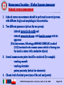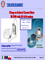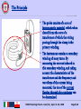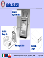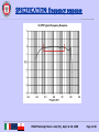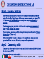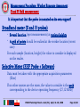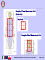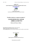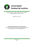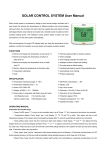
1
Strengthening of State supervision and monitoring system of exposure to electromagnetic fields Training on the use of modern control equipments for verification of EMF environmental assessment DIATHERMY Holaday HI 3702 Andrea Barellini, Andrea Zari, Lucia Ardoino [email protected], [email protected], [email protected] PHARE Twinning Poland – Lodz (PL), April, 14-18, 2008 Page 1/20 PART II - DIATHERMY Source Measurement procedure Measurement Devices (Clamp-on HI 3702 and Narda EHP200 probe+laptop) PHARE Twinning Poland – Lodz (PL), April, 14-18, 2008 Page 2/20 SOURCE – SHORTWAVE DIATHERMY SIGNAL: f = 27,12 MHz (CW) λ = 11 m CHARACTERISTICS: Max Power: 300 - 500 W typical used Power: ≈ 100 W capacitive / inductive electrode EXPOSURE reactive region the field is highly inhomogeneous !…very high field strength can occur near electrodes, power supply cables and connections … ! …can result in serious injury or death to patients with implanted devices with leads PHARE Twinning Poland – Lodz (PL), April, 14-18, 2008 Page 3/20 Basic restrictions and reference values Basic restrictions Diathermy equipment Shortwave diathermy (27,12 MHz) Microwave diathermy (2,45 GHz) Whole body Averaged SAR (W/kg) Localized SAR (head and trunk) (W/kg) Localized SAR (limbs) (W/kg) 0,4 10 20 0,4 10 20 Reference values (action values) Shortwave diathermy (27,12 MHz) Microwave diathermy (2,45 GHz) Electric field (V/m) Magnetic field (A/m) Limb induced current (mA) 61 0,16 100 137 0,36 - Action values must be averaged over a 6 minutes period PHARE Twinning Poland – Lodz (PL), April, 14-18, 2008 Page 4/20 Measurement Procedure - Worker Exposure Assessment What to measure ? • E field measurements with Broadband Meter • Induced current measurements with Clamp-on • H field measurements (broadband) should also be performed (we are not in far field region…) • Exploratory (preliminary) measurements around the place where the equipment is located to avoid inadvertent burnout and to detect other possible sources • Several location of measurements should be considered • Values must be averaged over a 6 minutes period • A grid of points should be realized at the worker location (worst case) PHARE Twinning Poland – Lodz (PL), April, 14-18, 2008 Page 5/20 Measurement Procedure - Worker Exposure Assessment Induced current measurement 1. Induced current measurements should be performed on several persons, with different height and morphological characteristics. 2. Two different parameters (at least for one person): • induced current in the ankle and • induced current in the arm, with hand in contact with the apparatus (This last measure, following prEN50413 CENELEC standard (5.3.3) is related to the contact current which is flowing into the hand in contact with conductive objects) 3. 4. Several measurements points should be considered (for example): • touching consolle • touching electrodes • patient proximity (behind the electrodes) Choose level of emitted power (max of the real used power) PHARE Twinning Poland – Lodz (PL), April, 14-18, 2008 Page 6/20 THE INSTRUMENT Clamp-on Induced Current Meter HI 3702 with HI 4416 readout • Frequency response: 9 kHz - 110 MHz • Dynamic range: a few mA - 1 A Clamp on probes, designed for induced currents, can also be used for contact currents, but not in the lower part of the frequency span PHARE Twinning Poland – Lodz (PL), April, 14-18, 2008 Page 7/20 The Principle The probe consists of a core of ferromagnetic material, which when closed forms the core of a transformer of which the wiring passing through the clamp is the primary winding. The instrument contains a secondary winding of many turns. By measuring the current induced in this secondary winding, and taking account the characteristics of the transformer and the frequency and waveform of the current being measured, the size of the current flowing through the conductor can be determined. PHARE Twinning Poland – Lodz (PL), April, 14-18, 2008 Page 8/20 Model HI-3702 The standard “kit” includes the following items: Model HI-3702 Clamp-On Current Sensor with cushioned case HI-4416 Digital Readout / Control Unit with Fiber Optic Cable 491198-36 Standard Fast Charger (115/230 V) User's Manual Fitted Carrying Case Optional accessories for the unit (for recording and downloading data): Belt-Pac Readout / Control Unit Case HI-4413G RS232 Serial Communication Adapter HI-3320 Datalogger PHARE Twinning Poland – Lodz (PL), April, 14-18, 2008 Page 9/20 Model HI-3702 HI-4416 Digital Readout HI-3702 Clamp-On Fiber Optic Cable 491198-36 Charger PHARE Twinning Poland – Lodz (PL), April, 14-18, 2008 Page 10/20 TECHNICAL SPECIFICATIONS Frequency Response 9 kHz to 110 MHz ± 2,0 dB Current dynamic range 1 mA – 1 A Linearity ± 0,5 dB; • At lower levels, the linearity for Range 1 deviates within ± 0,5 dB due to noise. • The other ranges follow the ideal curve as shown on the graph Relative Humidity 5% to 95%, non-condensing Operating Temperature +10 °C to +40 °C Operating ranges PHARE Twinning Poland – Lodz (PL), April, 14-18, 2008 Page 11/20 SPECIFICATION: frequency response PHARE Twinning Poland – Lodz (PL), April, 14-18, 2008 Page 12/20 OPERATING INSTRUCTIONS 1/3 Step 1 – Charging batteries It is recommended that the batteries be charged to maximum capacity using the standard fast charger before any measurements are taken (NiCd batteries will self-discharge to nearly zero capacity after only 2 months). The battery charger provided with the unit requires approximately 1 hour to fully charge the battery. Under normal operation, a fully charged battery should provide 5 hours of operation (Clamp-on). If the battery fails to hold a charge, or if a significant degradation in operational time occurs, the battery may need replacement. Step 2 - Connecting cable Connect the fiber optic cable to both the HI-4416 and the HI-3702 (both the devices are OFF) The connections are color coded … PHARE Twinning Poland – Lodz (PL), April, 14-18, 2008 Page 13/20 OPERATING INSTRUCTIONS 2/3 Step 3 – Switch ON Switch ON the HI-3702. (The HI-3702 is equipped with a locking lever on-off switch. This lever must be pulled out before toggling it to the appropriate position). Switch ON the HI-4416 readout. Step 4 – Use the HI-4416 unit (Details of operating the HI-4416 are documented in the HI-4416 Manual) • Use “Mode Select” key to move the cursor to select any function. • RANGE - select the range that is appropriate for the expected current levels to be measured. To select autorange, scroll through the ranges until “Range A” appears on the display. • ZEROING – pushing the ZERO key… PHARE Twinning Poland – Lodz (PL), April, 14-18, 2008 Page 14/20 OPERATING INSTRUCTIONS 3/3 • SET THE DATA COLLECTION RATE - select “X” for Instantaneous Readings, or “Y” for One-Second Averaging (The HI-3702 collects a measurement approximately seven times per second. The averaging algorithm stores the seven most recent measurements. Each time a measurement is taken, the algorithm drops the oldest value, adds in the new value, then recalculates the average and sends the new average value to the display). Step 5 – Place the Clamp-on on the arm Place the clamp-on current sensor on the arm or leg of the Body Under Test and close the buckle. It is important that nothing interferes with complete closure of the clamp-on sensor. Be sure that no pieces of clothing get caught … The Meter will record 150 s of data before filling the memory. Step 6 – Read Stored data Use “Prev” and “Next” keypads to scroll stored data (150 data points) PHARE Twinning Poland – Lodz (PL), April, 14-18, 2008 Page 15/20 Measurement Procedure: Worker Exposure Assessment E and H field measurement It is important that the probe is mounted on its own support! Broadband meter (E and H probes) • Several location (spot measurements) at various heights • A grid of points should be realized at the worker location (worst case) For each sample (location, height) the value to consider is displayed on the reader. Selective Meter (EHF Probe + Software) Data must be taken with the appropriate acquisition parameters (filter) If no other sources are the room, the value to consider is the peak corresponding to the device operating frequency (27,12 MHz) PHARE Twinning Poland – Lodz (PL), April, 14-18, 2008 Page 16/20 Example of Torso Measurement Grid (front view) (top view) Example of Head Measurement Grid PHARE Twinning Poland – Lodz (PL), April, 14-18, 2008 Page 17/20 RESULTS: how to verify the compliance? In order to verify the compliance… (the therapist usually moved all around the room and the exposure levels are different)… the following parameter must be determined: For Induced current: the square root of the time-weighted square mean of the values of the current in any limb over a total of 6 minutes period: Iavg = [(1/6min) ∑i(I i 2 dti)]1/2 For the E (/ H) field: the average (square mean) of the values obtained moving the probe in the points as in the suggested grid. PHARE Twinning Poland – Lodz (PL), April, 14-18, 2008 Page 18/20