1
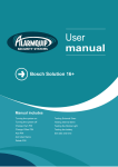
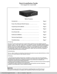
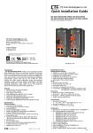
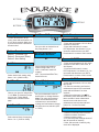
BUTTON 1
BUTTON 3
BUTTON 2
Setting Menu:
To enter Endurance II set up
menu, press and hold buttons 1,2,
& 3 for three seconds. Make sure
to press and hold all 3 buttons at
the same time!
Button Overview:
Button 1: Increment (Up)
Button 2: Decrement (Down)
Button 3: Next Setting
Set Time Of Day:
Screen 1: DST
Set your clock to desired time of
day using button 1 or 2.
Select Maintenance
Reminder Method:
Set Tire Size:
Choose your tire size using button
1 or 2. Note: To determine proper
tire size see: “Taking Wheel
Measurment” section on back
page.
Set Clock Format:
Select desired clock format using
button 1 or 2. (12HR or 24HR)
• Press and hold buttons 1 & 2 for three
seconds to reset DST.
• Press and hold button 3 to enter
DST adjustment. Use buttons 1 & 2 to
increment and decrement your DST.
Press button 3 to return to main screen.
Screen 2: DST2
Set Distance:
Select desired unit setting using
button 1 or 2. (KM/H or MH)
Quick Resets:
Select desired maintenance
method using button 1 or 2.
ODO = Odometer, based off
mileage.
ART = Accumulated Ride Time,
based off hours.
Select Maintenance
Reminder Interval:
Set your maintenance value to
desired time or mileage duration.
Note: This value will represent
either accumulated hours until
maintenance or accumulated
mileage until maintenance, based
off previous menu selection (ART
or ODO.)
• Press and hold buttons 1 & 2 for three
seconds to reset DST2, Ride Time, &
AVG Speed.
• Press and hold button 3 to enter
DST2 adjustment. Use buttons 1 & 2 to
increment and decrement your DST2.
Press button 3 to return to main screen.
Screen 3: ODO
• Press and hold buttons 1 & 2 to reset
Max Speed.
• To view time remaining until service
maintenance interval icon is activated
press and hold Button 3 for three
seconds.
• When the maintenance icon
is
illuminated, press and hold button 3 for
three seconds to enter maintenance
interval screen and then to reset
maintenance interval press and hold
button 1 & 2 for three seconds.
Notes:
1. Wakes on external power from bike.
2. Wakes on wheel movement.
3. Wakes on button press.
4. On external power backlight shuts off
after 90 seconds of inactivity.
5. After 180 seconds of inactivity only
clock will be displayed.
Motorcycle Sensor/Magnet Installation
Method 1: Ruler Measurement Method
Power Wire Installation
Wheel Size=
Wheel Diameter(mm)
x 3.14
Diameter(mm)
x 3.14
Power Wire
Magnet About to Pass Under Sensor
Motorcycles & ATV’s require a magnet
placed on a rotating surface such as
the front or rear wheel and a sensor
opposite the magnet to create a wheel
sensor pick up.
Magnets are offered in a variety
of options such as a magnetic
replacement rotor bolt, or a small
neodymium magnet you can adhere to
a rotating surface.
The wheel sensor is best installed
allowing the wheel sensor lead to
route along side the front or rear
brake lines to prevent damage during
riding as well as a clean wire routing
installation.
Most motorcycles & ATV’s require
a model specific wheel sensor and
magnet application. Refer to provided
installation sheet insert for properly
installing your wheel sensor and
magnet.
Optimum Magnet Rotation Path
Taking Wheel Measurement
Find the diameter of the wheel being
used during installation in millimeters.
Take the diameter and multiple it by
3.14 to identify the wheels rolling
circumference. The diameter in
millimeters is the value you will use as
your tire size. Enter this number during
your initial set up.
Note: Although any rotating surface
can be used to measure wheel speed
the front wheel is the easiest method
of installation. If you measured the
diameter of your wheel in inches,
first multiply your diameter by 25.4
to convert it into millimeters. Once
converted follow the instructions
outlined in the previous section to
complete this process.
Method 2: Rolling Measurement
On a flat surface, mark the tire sidewall
and the ground with a marker or piece
of chalk. Roll the wheel until the mark
on the tire has made one 360 degree
rotation and is lined up to the ground.
Mark this location on the ground lining
up to the mark on the tire sidewall.
Measure the distance between the
two marks made on the ground. If this
measurement is in inches multiply your
measurement by 25.4 to convert it into
Millimeters. If your measurement is
in millimeters discard this conversion
process. The measurement taken in
the rolling circumference of your wheel
and will be used as your tire size during
initial set up mode of you computer.
Wired to
Vehicle
Battery:
Connect
the power
wire to the
vehicle
battery
and to
Endurance II. A 0.5A fuse (not
provided) should be used between
the power cable and positive battery
terminal when connecting directly to
a battery.
Endurance II is polarity independent,
so it cannot be installed backwards.
Use zip-ties to secure the cable to
the bike as
it is routed to Endurance II.
System Tap: The possible points to
tap into the vehicle electrical system
are at the lights, ignition, or CDI.
When tapping into the electrical
system, connect to a circuit protected
by fuse. It is best to connect so
power is not interrupted by key
switch.
MX Bikes: Motocross bikes do not
have 12 volt power. For connection
to an MX bike, connect power leads
to ignition power leads from stator.
Use caution, as this is a high voltage
option.
Endurance II will operate in the range
of 9.0-55VDC/9.0-400VAC, but will
not draw enough power to drain a
vehicle battery.