1
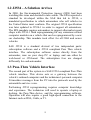
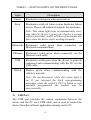
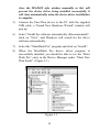
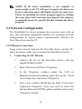
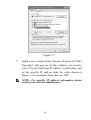
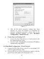
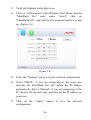
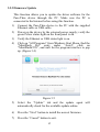
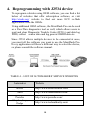
Table of Contents 1. INTRODUCTION ....................................................................................... 1 1.1 BACKGROUND ............................................................................................. 1 1.2 J2534 - A SOLUTION ARRIVES.................................................................... 2 1.3 PASS-THRU VEHICLE INTERFACE .............................................................. 2 2. GETTING TO KNOW MAXIFLASH PRO .............................................. 3 2.1 FRONT PANEL ............................................................................................. 3 2.2 REAR PANEL ............................................................................................... 5 2.3 POWER UP .................................................................................................. 7 2.4 SPECIFICATIONS ......................................................................................... 7 2.5 ACCESSORIES INCLUDED ............................................................................ 9 2.6 PRODUCT TROUBLESHOOTING .................................................................. 10 3. DRIVER SETUP & NETWORK CONFIGURING ................................ 11 3.1 DRIVER SETUP ........................................................................................... 11 3.2 NETWORK CONFIGURATION ...................................................................... 13 4. REPROGRAMMING WITH J2534 DEVICE ......................................... 18 5. COMPLIANCE INFORMATION ............................................................ 20 6. WARRANTY AND SERVICE .................................................................. 21 6.1 LIMITED ONE YEAR WARRANTY .............................................................. 21 6.2 SERVICE PROCEDURES .............................................................................. 21 1. Introduction 1.1 Background The days of diagnosing and repairing automobiles without a laptop beside you are quickly fading. Newer vehicles include a large number of onboard computers that are each dedicated to performing specific tasks. Common onboard computers in newer vehicle include the Engine Control Module (ECM), Transmission Control Module (TCM), Fuel Injection Control Module (FICM), Anti-lock Brake System (ABS), Body Control Module (BCM) and numerous other control modules to manage every electronic system from power door locks to crash data. Each onboard computer is programmed at the factory with software enabling it to perform certain tasks. Inside the ECM is software containing hundreds or even thousands of parameters to control spark, fuel, idle, cruising, emissions, economy, drivability, and performance. Likewise, a TCM will have software to control how the transmission and torque converter function. Sometimes, after the vehicle is shipped from the automaker, updates are released to improve emissions, fuel economy, drivability, performance, or specific bugs in the original software that have caused warranty issues. Updating this software can be a proactive fix because often it will resolve problems that a customer hasn’t reported or noticed yet. The practice of updating software in these modules is more commonly known as flash reprogramming. At new car dealerships, flash reprogramming is relatively straight forward because service technicians are connected to the automaker and have the expensive, specialized dealer service tools dedicated to reprogramming. The independent repair shops have faced a more difficult challenge because most shops typically service more than one make of vehicles. This increases the complexity, cost and training required to operate dozens of different factory service tools. 1 1.2 J2534 - A Solution Arrives In 2000, the Environmental Protection Agency (EPA) had been watching this issue and decided to take action. The EPA requested a standard be developed within the SAE that led to J2534, a mandated specification to which automakers who sell vehicles in the United States must conform. The original J2534 specification was later updated to J2534-1 in order to support all automakers. The EPA mandate requires automakers to support aftermarket repair shops with J2534-1 flash reprogramming for any emissions related computer modules on a vehicle that can be reprogrammed by a new car dealership. This mandate took effect for all 2004 and newer vehicles. SAE J2534 is a standard devised of two independent parts: subscription software and a J2534 compliant Pass Thru vehicle interface. The subscription software comes directly from the automaker, runs on your shop PC or laptop, and can either be web-based or CD-based. The subscription fees are charged differently for each automaker. 1.3 Pass-Thru Vehicle Interface The second part of the system is a SAE J2534 compliant Pass-Thru vehicle interface. This device acts as a gateway between the vehicle’s onboard computers and the technician’s personal computer. It translates messages from the PC into the protocols used by the automobile and vice versa. Performing J2534 reprogramming requires computer knowledge and experience. The technician will need to operate a laptop or desktop, the Pass-Thru device, and the reprogramming software. Operation will also require a good high-speed connection to the Internet such as DSL, Cable, or T1. 2 2. Getting to Know MaxiFlash Pro Thank you for choosing the MaxiFlash® Pro Reprogramming Device! This multi-protocol Pass-Thru vehicle interface is a fully compliant SAE J2534-1 & SAE J2534-2 (March 2006) device, specially designed to provide users with convenient PC communication and ECU reprogramming capabilities on any modern vehicle diagnostic bus, and offer the most significant features desired by OEM customers: reliability, fast performance and flexibility. 2.1 Front Panel The MaxiFlash® Pro Pass-Thru device supports three ways of PC connection: Ethernet, USB and Bluetooth, which make PC communication and vehicle reprogramming all the more convenient and easy for technicians. These three connection ports to the PC are available in the front panel of the device. 1) Status Lights There are 6 status lights on the front panel of the reprogramming tool, which indicates the Pass-Thru interface’s working status as well as the hardware conditions, and are very useful for troubleshooting the device’s communication or connection to the Vehicle or PC. Please refer to Table 1 for detailed description of the status lights. 3 TABLE 1—STATUS LIGHTS ON THE FRONT PANEL Light Description Power Illuminates solid green when powered on. Error Illuminates solid red when serious hardware failure occurs. Please call technical supports for assistance. Note: This status light turns on automatically every time when the device is power up, which is a normal self-test procedure, and it will turn off automatically later when the device starts working normally. Bluetooth Illuminates solid green when connected via Bluetooth communication. Ethernet Illuminates solid green when connected via the Ethernet serial cable. USB Illuminates solid green when the device is properly connected and communicating with the PC via the USB cable. Vehicle Flashes green when communicating with the vehicle’s network. Note: Do not disconnect while this status light is on! If you interrupt the flash reprogramming procedure while the vehicle’s ECU is blank or only partially programmed, the module may be unrecoverable. 2) USB Port The USB port provides the easiest connection between the device and the PC via a USB cable, and is used to control the device from the software application running on the PC. 4 3) Ethernet Port The Ethernet port connects the device to the PC directly or through an existing network via an Ethernet cable, which supports longer range and higher performance. NOTE: There’re two status lights at the bottom corners alongside the Ethernet Port, which illuminate when the device is properly connected to the PC or an existing network through the Ethernet Cable. 4) Bluetooth Antenna The Bluetooth antenna, which offers higher bandwidth and distance range, can be detected and paired to Autel’s MaxiSys diagnostic tablet and serves as a Vehicle Communication Interface (VCI) device for data transmission. 2.2 Rear Panel Connections to the power adapter, vehicle, external programming voltage, and analog inputs are available on the rear panel. 1) Power Port The power port (DC 12V) connects the device and the power source with the adapter, which supplies power to the reprogramming tool. 5 2) Vehicle Connector The Vehicle connector connects the device to the vehicle’s DLC via a standard high density DB-26 MVCI – OBDII cable. 3) External Programming Voltage Output The external programming socket provides the user with access to the 5-20V programming voltage. This is used for Mitsubishi, Subaru or any other vehicle that needs voltage on an additional connector. 4) A/D Inputs The 12-bit analog inputs are setup for an input range of 0 27.5VDC and are electrically protected against reverse voltage and over voltage conditions. The Mating connector is a High Density DB-15. TABLE 2 – GENERAL PURPOSE ANALOG INPUTS Pin Function Direction 2 Channel 6 In 4 Channel 3 In 6 Battery Voltage Out (200mA max) 8 Channel 4 In 10 Channel 1 In 12 Channel 5 In 14 Channel 2 In 1,3,5,7,9, Ground 11,13,15 6 2.3 Power Up The Pass-Thru vehicle reprogramming device can be powered either via the vehicle DLC, or the external power adapter. Vehicle Power Supply Connect the MVCI – OBDII cable to the reprogramming tool. 2) Find DLC on vehicle. A plastic DLC cover may be found for some vehicles and you need to remove it before plugging the OBDII cable. 1) 3) Plug OBDII cable to the vehicle’s DLC. 4) Wait for the reprogramming tool to power up. External DC Power Supply 1) Locate the power port of the device. 2) Connect the device and the power source with the power adapter. 3) Wait for the reprogramming tool to power up. The external power supply is necessary for off-board reprogramming, and since this reprogramming tool does not receive power from the PC’s Ethernet or USB ports, it is also needed when the device is communicating applications on the PC. NOTE: The external power supply does not support power charging to the vehicle battery. 2.4 Specifications The MaxiFalsh® Pro Reprogramming Device is powerfully featured to be desired by all OEM customers: 7 Supports simultaneous communication definition in J2534-1, running 3 protocols at the same time, which greatly improves reprogramming and diagnostic speed. Supports multiple device connections to the PC, which can operate diagnostic and reprogramming functions on more than one vehicle at the same time. Embedded with the ARM9 Dual-core processor (clocked up to 500MHz), which further boosts the communicating speed. Rugged aluminum case with non-slip rubber end caps, capable of withstanding harsh environment. Check up detailed specifications in the following table: TABLE 3 – DEVICE SPECIFICATIONS Name Value Input Voltage Range 6VDC to 26VDC Supply Current 350mA @ 6VDC 200mA @ 12VDC 110mA @ 24VDC Operating Temperature 0℃ to +60℃ (ambient) Storage Temperature -65℃ to +100℃ (ambient) Dimensions Length: 183.8 mm (7.23") Width: 135.5mm (5.33") Height: 41 mm (1.6") Weight 0.54kg (1.20lb) 8 Bus Protocols Primary CAN / ISO15765 / GMLAN Secondary CAN / ISO15765 / GMLAN (Dual or Single Wire) Ford SCP (J1850PWM) GM Class2 (J1850VPW) KWP2000 (ISO9141 / 14230) Chrysler SCI (J2610) Other Compliant to SAE J2534-1 (2004) and J2534-2 (2006) reprogramming standards Compliant to ISO 22900-1 MVCI physical layer Programming voltage on all J1962 pins (except 4, 5, and 16) or Aux Ground pins 1,2,9,12, or 15 2.5 Accessories Included 1) 2) 3) 4) 5) 6) 7) User’s Manual - Instructions on tool operations MVCI to OBDII Cable - provides power to tool and communicates between tool and vehicle, high density DB-26 USB Cable - allows easy connection to PC Ethernet Cable - connects to PC or an existing network Bluetooth Antenna – receives wireless network signals Power Adapter - supplies power to the reprogramming tool. CD - includes user’s manual, software development kit, device driver, etc 9 The following accessories are optional items according to your demand, available and buyable from Autel directly or the local agents or dealers: 8) 9) Analog Input Line - measures voltage levels External Programming Voltage Output Line - provides access to the 5-20V programming voltage 2.6 Product Troubleshooting This part describes problems that you may encounter while using the reprogramming tool. Vehicle Linking Error A communication error occurs if the reprogramming tool fails to communicate with the vehicle’s control module when perform the program re-flash. You need to do the following check-ups: Verify that the ignition is ON. Check if the reprogramming tool’s OBD II connector is securely connected to the vehicle’s DLC. Turn the ignition off and wait for about 10 seconds. Turn the ignition back to on and continue the operation. Verify the control module is not defective. PC Communication Error If you cannot communicate the device to the PC, you need to do the following check-ups: Verify the reprogramming tool is powered, and the green power LED is illuminated. Check if there is any firewall software interfering with the connection port. Check if the green status light is illuminated for Ethernet, USB, or Bluetooth. If these issues have been addressed, verified, and you are still having trouble, please contact technical supports for assistance. 10 3. Driver Setup & Network Configuring 3.1 Driver Setup In order for the Pass-Thru Device to operate correctly with the re-flashing and diagnostic applications on the target PC, you will need to first install the MaxiFlash Pro J2534 device driver onto the PC that will control the device. To setup the J2534 Pass-Thru device driver, you will need the followings: CD with the device driver program PC or laptop with USB ports J2534 Pass-Thru reprogramming tool USB cable NOTE: The following steps may vary depending on the operating system or components that are installed on your computer, but in general this is the standard installation process. 1) Insert the driver installation CD to your PC. The driver installation wizard will load momentarily. 2) Click on ―Next‖ on the welcome page. 3) Select ―Next‖ on the installation location and installation name. It is recommended not to change the default settings; otherwise the computer may have a hard time recognizing the driver. 4) Click ―Install‖ and the driver program will be installed onto your PC. NOTE: During this part of the process a MS-DOS style window will pop up and may remain on your screen for a short while, which is perfectly normal. Do not attempt to 11 close the MS-DOS style window manually as this will prevent the device driver being installed successfully, it will close automatically when the device driver installation is complete. 5) Connect the Pass-Thru device to the PC with the supplied USB cable, a ―Found New Hardware Wizard‖ window will pop up. 6) Select ―Install the software automatically (Recommended)‖, click on ―Next‖, and Windows will search for the driver software automatically. 7) Select the ―MaxiFlash Pro‖ program and click on ―Install‖. 8) When the MaxiFlash Pro device driver program is successfully installed, you should be able to see the ―Maxi Flash Pro‖ entry in the Device Manager under ―Maxi Pass Thru Serial‖. (Figure 3.1) Figure 3.1 12 NOTE: If the driver installation is not complete or unsuccessful, or the PC still can’t recognize the device, an Error or Question mark will display beside the entry icon. Please try installing the driver program again by clicking the entry, then select start auto searching for the software, or manually locate the specific file that contains the driver program. 3.2 Network Configuration The MaxiFlash Pro device program also provides users with an easy and convenient application interface for operating network configurations to ensure proper communication between the Pass-Thru device and the PC. 3.2.1 Ethernet Connection Using wired network between the Pass-Thru device and the PC, users can choose either way of connection described as below: Connecting to a PC Directly 1. Connect the PC to the Pass-Thru device with the supplied Ethernet cable. 2. Open ―My Network Places‖ Properties. 3. In the Properties window, under the LAN or High-Speed Internet heading, right click on the ―Local Area Connection‖ and select ―Properties‖. 4. Now a new window should pop up, titled ―Local Area Connection Properties‖. Here you need to select the Internet Protocol (TCP/IP) option, and then click on the ―Properties‖ button. 13 Figure 3.2 5. Again a new window titled "Internet Protocol (TCP/IP) Properties" will pop up. In this window, you need to select "Use the following IP Address" radio button, and set the specific IP address (take the value shown in Figure 3.3 for example), then click on ―OK‖. NOTE: For specific IP address information please contact your network administrator. 14 Figure 3.3 6. After all the above properties settings have been properly set, users can continue on completing the network configuring procedure, please refer to the detailed operation guidance in 3.2.2. MaxiFlash Configuration – Wired Network. Connecting to an Existing LAN 1. 2. Connect the Pass-Thru device to a local network with the supplied Ethernet Cable. On most LANs, MaxiFlash Pro can obtain its IP address automatically using DHCP. 3.2.2 MaxiFlash Configuration – Wired Network 1) 2) Connect the Pass-Thru device to the PC or an existing LAN with the supplied Ethernet cable. Power up the device by the external power supply; verify the green Power status light on the front panel is on. 15 3) Verify the Ethernet status light is on. 4) Click on ―All Programs‖ from Windows Start Menu, find the ―MaxiFlash Pro‖ entry under ―Autel‖, click on ―MaxiFlashCFG‖, and wait for the program interface to pop up. (Figure 3.4) Figure 3.4 5) Select the ―Settings‖ tab to set up the network configuration. 6) Select ―DHCP‖, if you are connecting to the local area network, the MaxiFlash Pro will obtain the IP address automatically. Select ―Manual‖, if you are connecting to the PC directly for the first time, and then set the IP address on your own. 7) Click on the ―Apply‖ button to save the network configuration. 16 3.2.3 Firmware Update This function allows you to update the driver software for the Pass-Thru device through the PC. Make sure the PC is connected to the Internet before using this function. 1) Connect the Pass-Thru device to the PC with the supplied Ethernet cable or USB cable. 2) Power up the device by the external power supply; verify the green Power status light on the front panel is on. 3) Verify the Ethernet or USB status light is on. 4) Click on ―All Programs‖ from Windows Start Menu, find the ―MaxiFlash Pro‖ entry under ―Autel‖, click on ―MaxiFlashCFG‖, and wait for the program interface to pop up. (Figure 3.4) Figure 3.5 5) Select the ―Update‖ tab and the update agent will automatically check for the available update online. 6) Press the ―Next‖ button to install the newest firmware. 7) Press the ―Cancel‖ button to exit. 17 4. Reprogramming with J2534 device To reprogram vehicles using OEM software, you can find a list below of websites that offer subscription software, or visit http://etools.org/ website to find out more ECU re-flash applications from the OEMs. Using additional OEM software, the MaxiFlash Pro can be used as a Pass-Thru diagnostics tool as well, which allows users to read and clear Diagnostic Trouble Codes (DTCs) and data log PIDS, collect sensor data and log generic OBDII data etc. Since J2534 allows multiple devices to be connected at once, you must tell the software you want to use the MaxiFlash Pro. Every application will have a different way to select the device, so please consult the software manual. TABLE 4 – LIST OF AUTOMAKERS’ SERVICE WEBSITES Automaker Website BMW http://www.bmwtechinfo.com/ Mini http://www.minitechinfo.com/ Porsche Chrysler, Jeep, Dodge http://www.porsche.com/ http://www.techauthority.com/ 18 Automaker Website Ford, Lincoln, Mercury, http://www.motorcraft.com/ Land Rover http://www.landrovertechinfo.com/ Volvo Cadillac, Chevrolet, Daewoo, GM, GEO, Pontiac, Buick, Saturn, SAAB Acura, Honda http://www.volvotechinfo.com/ Isuzu http://www.isuzutechinfo.com/ Mazda http://www.mazdaserviceinfo.com/ http://www.gmtechinfo.com/ http://www.serviceexpress.honda.com/ Mercedes http://www.startekinfo.com/ Mitsubishi http://www.mitsubishitechinfo.com/ Nissan Toyota, Lexus, Scion Volkswagen Audi http://www.nissan-techinfo.com http://techinfo.toyota.com/ http://www.erwin.volkswagen.de/erWin VW http://erwin.audi.de/erWinAudi NOTE: When reprogramming onboard, always make sure the vehicle battery is fully charged and in good working condition. During reprogramming there is a risk of having the operation failure if voltage falls below the proper operating voltage. Sometimes a failed operation can be recovered, but there is a chance that failed reprogramming could ruin the control module. We recommend connecting an external battery charger to the vehicle to ensure a successful operation. 19 5. Compliance Information FCC COMPLIANCE FCC ID: WQ82012J2534 This device complies with Part 15 of the FCC Rules and with RSS-210 of Industry Canada. Operation is subject to the following two conditions: 1. 2. This device may not cause harmful interference. This device must accept any interference received, including interference that may cause undesired operation. Warning: Changes or modifications not expressly approved by the party responsible for compliance could void the user's authority to operate the equipment. NOTE: This equipment has been tested and found to comply with the limits for a Class B digital device, pursuant to Part 15 of the FCC Rules. These limits are designed to provide reasonable protection against harmful interference in a residential installation. This equipment generates uses and can radiate radio frequency energy and, if not installed and used in accordance with the instructions, may cause harmful interference to radio communications. However, there is no guarantee that interference will not occur in a particular installation. If this equipment does cause harmful interference to radio or television reception, which can be determined by turning the equipment off and on, the user is encouraged to try to correct the interference by one or more of the following measures: ⅰ. Reorient or relocate the receiving antenna. ⅱ. Increase the separation between the equipment and receiver. ⅲ. Connect the equipment into an outlet on a circuit different from that to which the receiver is connected. ⅳ. Consult the dealer or an experienced radio/TV technician for help. FCC Radiation Exposure Statement: This equipment complies with FCC radiation exposure limits set forth for an uncontrolled environment. This equipment should be installed and operated with minimum distance 20cm between the radiator & your body. RoHS COMPLIANCE This device is declared to be in compliance with the European RoHS Directive 2011/65/EU. CE COMPLIANCE This product is declared to conform to the essential requirements of the following Directives and carries the CE mark accordingly: EMC Directive 2004/108/EC R&TTE Directive 1999/5/EC Low Voltage Directive 2006/95/EC 20 6. Warranty and Service 6.1 Limited One Year Warranty Autel warrants to its customers that this product will be free from all defects in materials and workmanship for a period of one (1) year from the date of the original purchase, subject to the following terms and conditions: 1) The sole responsibility of Autel under the Warranty is limited to either the repair or, at the option of Autel, replacement of the Pass-Thru device at no charge with Proof of Purchase. The sales receipt may be used for this purpose. 2) This warranty does not apply to damages caused by improper use, accident, flood, lightning, or if the product was altered or repaired by anyone other than the Manufacturer’s Service Center. 3) Autel shall not be liable for any incidental or consequential damages arising from the use, misuse, or mounting of the device. Some states do not allow limitations on how long an implied warranty lasts, so the above limitations may not apply to you. 4) All information in this manual is based on the latest information available at the time of publication and no warranty can be made for its accuracy or completeness. Autel reserves the right to make changes at any time without notice. 6.2 Service Procedures If you have any questions, please contact your local store, distributor or visit our website at www.auteltech.com. If it becomes necessary to return the tool for repair, contact your local distributor for more information. 21