1
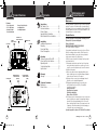
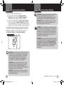
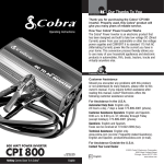
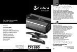
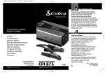
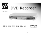
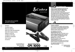
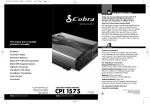
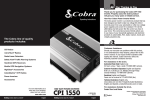
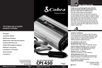
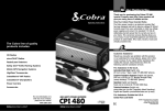
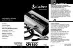
Main Icons
Our Thanks to You
Introduction
Intro
Operation
Customer
Warranty
Thank you for purchasing Assistance
the Cobra Power
Inverter CPI890. Properly used, this Cobra product
will give you many years of reliable service.
Operating Instructions
Main Icons
The Cobra line of quality
products includes:
How Your Cobra Power Inverter Works
Installation
Notes
The Cobra power inverter
is an electronic product
that
has been
designed
and
built
to
take
low
voltage
DC
Secondary Icons
(Direct Current) power from your automobile or other
low voltage power supplies and convert it to standard
115 Volt AC (Alternating Current) power like the current
you have in your home. This conversion process
thereby allows you Notice
Caution
Warning
to use many of your household appliances and
electronic products in automobiles, RVs, boats, tractors,
trucks and virtually anywhere else.
Customer Assistance
Intro
CB Radios
microTALK® 2-Way Radios
Radar/Laser Detectors
Mobile GPS Navigation Systems
Secondary Icons
HighGear® Accessories
Power Inverters
Accessories
For more information or to
order any of our products,
please visit our website:
www.cobra.com
CPI890_MANL.indd 1-3
Customer
Assistance
Warranty
Customer Assistance
Should you encounter any problems with this product,
or not understand its many features, please refer to this
owner’s manual. If you
require further assistance after
Installation
Notes
reading this manual, Cobra Electronics offers the
following customer assistance services:
For Assistance in the U.S.A.
Automated Help Desk English only.
24 hours a day, 7 days a week 773-889-3087 (phone).
Notice
Caution
Warning
Customer Assistance Operators English and Spanish.
8:00 a.m. to 5:30 p.m. CT, Monday through Friday
(except holidays) 773-889-3087 (phone).
Questions English and Spanish.
Faxes can be received at 773-622-2269 (fax).
Technical Assistance English only.
www.cobra.com (on-line: Frequently Asked Questions).
English and Spanish. [email protected] (e-mail).
CobraMarine® VHF Radios
Nothing Comes Close to a Cobra®
Operation
800 WATT POWER INVERTER
CPI 890
For Assistance Outside the U.S.A.
Printed in China
Part No. 480-995-P
Version B
A1
©2014 Cobra Electronics Corporation
6500 West Cortland Street
Chicago, Illinois 60707 USA
www.cobra.com
Nothing Comes Close to a Cobra®
11/13/14 3:44 PM
Main Icons
Main Icons
Product Features
Introduction
Intro
Operation
Features
• Two AC Receptacles
• 5V / 2.1 USB Output
• Automatic Thermal
Protection/Shutdown
Installation
Customer
Assistance
Introduction
Intro
Main Icons
Notes
Secondary Icons
Intro
AC Outlet
On/Off
Power Switch
Notice
Caution
Warning
Secondary Icons
Installation
Main Icons
Secondary Icons
POWER /
FAULT
Cooling Fan
Negative Battery
Cable Terminal
(Black)
Notice
Operation
Main Icons
Installation
Main Icons
Positive Battery
Cable Terminal
(Red)
Intro
Secondary Icons
Operation
Intro
Customer
Assistance
Warranty
Operation
Customer
Notice
Assistance
Installation
Intro
11
12
13
14
15
Customer Assistance
Maintenance. . . . . . . . . . . . . . . . . . . . . . . 17
Product
ServiceWarning
. . . . . . . . . . . . . . . . . . . . 17
Warranty
Caution
Notes
Secondary Icons
Caution
Warning
Warranty
Notes
Warranty . . . . . . . . . . . . . . . . . . . . . . . . . 16
Notes
Installation
Caution
Operation
Turning Your Inverter On or Off. . . . . . . .
Power
and Protection
Caution
Warning Indicators . . . . . . .
Customer
Warranty
Assistance Limits . . . . . . . . . . . . . . . . . . .
Operating
Troubleshooting Guide. . . . . . . . . . . . . . .
Specifications. . . . . . . . . . . . . . . . . . . . . .
Secondary Icons
Notice
Warranty
Installation
Notes
Installation
Installation Requirements . . . . . . . . . . . . . 5
Notice
Caution
Warning
Mounting . . . . . . . . . . . . . . . . . . . . . . . . . . 6
Notes
Connecting Cables . . . . . . . . . . . . . . . . . . . 7
Power Consumption . . . . . . . . . . . . . . . . 10
Notice
USB
Intro
POWER
Customer
Assistance
Assistance
USB Outlet
AC Outlet
Operation
Customer Assistance
Introduction
Our Thanks to You . . . . . . . . . . . . . . . . . . A1
Customer
. . . . . . . . . . . . A1
Intro
Operation Assistance
Customer . . . .Warranty
Assistance
Product Installation
Features
. . . . . . . . . . . Notes
. . . . . . . . A2
Important
Safety
Information
.
.
.
........ 1
Secondary Icons
Operation Quick
Customer
Warranty
Evaluation
Before Installation. . . . . .Secondary
3 Icons
• Reverse Polarity Protection
• Low Battery Alarm
• Low Battery Shutdown
Protection &
Power Indicators
Contents
Main Icons
Warranty
Main Icons
Warning
Operation
Customer
Maintenance
Assistance
Maintenance and
Product Service
Warranty
Very little maintenance is required to keep the inverter operating
properly. The exterior of the unit should be cleaned periodically
with a damp cloth to prevent accumulation of dust and dirt. At the
same time, tighten the screws on the DC input terminals. Be sure
Installation
vents and fans are freeNotes
of dust or debris.
Product Service
•
•
If you have any questions about operating or installing your new
Cobra product, or if you are missing parts…
Please call Cobra first!
DO NOT RETURN
THIS Warning
PRODUCT TO THE STORE!
Caution
See customer assistance on page A1.
Notice
If your product should require factory service, please call Cobra
first before sending your power inverter. This will ensure the
fastest turn-around time on your repair. You may be asked to
send your power inverter to the Cobra factory.
It will be necessary to furnish the following to have the product
serviced and returned.
1. For warranty repair include some form of proof-of-purchase,
such as a mechanical reproduction or carbon copy of a sales
receipt. If you send the original receipt, it cannot be returned.
2. Send the entire product.
3. Enclose a description of what is happening with the power
inverter. Include a typed or clearly printed name and address
of where the power inverter is to be returned.
4. Pack power inverter securely to prevent damage in transit.
If possible, use the original packing material.
5. Ship prepaid and insured by way of a traceable carrier
such as United Parcel Service (UPS) or Priority Mail
to avoid loss in transit to:
Cobra Factory Service
Cobra Electronics Corporation
6500 West Cortland Street
Chicago, Illinois 60707 USA.
6. If the power inverter is in warranty, upon receipt of your power
inverter, it will either be repaired or exchanged depending on
the model. Please allow approximately three to four weeks
before contacting Cobra for status. If the power inverter is out
of warranty, a letter will automatically be sent informing you
of the repair charge or replacement charge.
If you have any questions, please call 773-889-3087 for assistance.
Notice
A2
CPI890_MANL.indd 4-6
Caution
A3
Warning
Nothing Comes Close to a Cobra®
17
11/13/14 3:44 PM
Main Icons
Intro
Customer
Assistance
o
Operation
on
e
n
Customer
Caution
Warranty
Before installing and using your Cobra power inverter,
please
read these general precautions and warnings.
Warranty
•
Caution and Warning
InstallationStatements
Notes
To make the most of this inverter, it must be installed
Secondary Icons
and used
properly.
Please read the installation and
Customer
Warranty
Assistance
operating
instructions carefully before installing and
Notes
using it. Special attention must be paid to the CAUTION
and WARNING statements in the manual.
Notice
Caution
Warning
Notes
CAUTION
Statements
specify
conditions
which
could cause damage to the unit or other equipment.
Installation
Warning
WARNING Statements identify conditions that
could result in personal injury or loss of life.
Main Icons
Notice
Intro
Secondary Icons
Customer
Assistance
Caution
Warning
General Precautions
1. Never install the inverter in a boat’s
engine compartment where gas and
Operation
Customer
Warranty
Assistance
battery fumes
are present.
2. Do not operate the inverter if it has
been dropped or damaged in any way.
3. Installation
Do not open the inverter;
it contains no userNotes
serviceable parts. Attempting to service unit
could cause electrical shock.
Warranty
NOTE Internal components remain charged
after all power is disconnected.
Notice
Caution
Warning
4. Do
not expose
the inverter
to rain, snow,
bilge water or spray.
5. Do not obstruct the ventilation openings.
Notes
6. Do not install the inverter in zero-clearance
compartment.
on
e
Operation
Assistance
Important Safety Information
on
ons
Important Safety Information
Introduction
CAUTION This inverter should be used in
negative ground applications only.
Caution
Warning
CPI890_MANL.indd 1
Nothing Comes Close to a Cobra®
1
11/13/14 3:44 PM
o
Operation
Customer
Warranty
Assistance
Main Icons
Installation
Notes
Introduction
ons
Main Icons
Important Safety Information
Intro
Notice
Caution
Operation
Customer
Warranty
Assistance
WARNING Power inverters
contain components
that can produce arcs or sparks. To prevent fire
or explosion,
do not install the inverter in areas or
Warning
compartments containing batteries or flammable
materials or Installation
in locations that requireNotes
ignitionprotected equipment.
Secondary Icons
WARNING To reduce the risk of fire, do not cover
or obstruct the ventilation openings. Do not
install inverter in zero-clearance compartment.
Notice
Caution
Warning
Proposition 65: Warning:
Wash
Hands
After
Handling Power Cord
The power cord on this product contains lead, a chemical
known in the state of California to cause birth defects or
other reproductive harm.
Caution: Rechargeable Appliances
Certain chargers for small nickel cadmium batteries can be
damaged if connected to the Cobra 800 watt inverter. Two
particular types of equipment are prone to this problem:
1. Small battery-operated
appliances such as flashlights,
razors, and night lights that
can be plugged directly into
an AC receptacle to recharge.
2.
Certain
battery chargers for
Dangerous
Voltages
battery packs used in hand
power tools. These chargers
have a WARNING label stating
that dangerous voltages are
present at the battery terminals.
This problem does not occur with the vast majority of
battery operated equipment. Most use a separate charger
or transformer that is plugged into the AC receptacle
and produces a low voltage output. If the label on the AC
adapter or charger states that it produces a low voltage
AC or DC output (less than 30 volts), the inverter will
have no problem powering the adapter safely.
Plug In Directly
2
CPI890_MANL.indd 2-3
Quick Evaluation
Before Installation
Introduction
Intro
Operation
Customer
Warranty
Assistance
Output Waveform
Some very sensitive electronic equipment may not operate
satisfactory on “square wave” or “modified sine wave.”
The output waveform is referred to as “square wave” or
“modified sine wave.”
It is a stepped waveform
designed
Installation
Notes
to have characteristics similar to the sine wave shape of
utilitySecondary
power.Icons
A waveform of this nature is suitable for most
AC loads (including linear and switching power suppliers
used in electronic equipment, transformers and motors).
Quick Evaluation Before Installation
Notice
Caution
Warning
This section provides you with basic information about the
inverter and how to check its performance before installation.
•
Be Sure to Have on Hand:
£ A 12 volt DC power source (such as a vehicle battery).
The power source must provide
Power Supply
between 11 and 15 volts DC and
be able to supply enough current to
run the test load. As a rough guide,
divide the wattage of the test load by
10 to get the current (in amperes)
the power source must deliver.
£ The provided two foot direct-to-battery 12 gauge cable.
Only use the cable provided with
Cable
your inverter.
£ A test load that can be plugged into the AC receptacle on
the inverter for short term testing at a low power level.
Test Load
Nothing Comes Close to a Cobra®
3
11/13/14 3:44 PM
Main Icons
Intro
Intro
Operation
Customer
Assistance
Quick Evaluation
Before Installation
Introduction
Intro
Operation
Customer
Installation
Warranty
Assistance
Notes before installation:
To check yourInstallation
inverter’s performance
POWER /
1.
Turn
the
inverter off (see page
Secondary Icons
FAULT
On/Off Switch to Off
USB
11 for details). If the power
source is a DC power supply,
Installation switch it off as well.
Notes
POWER
Notice
Caution
Warning
2.
Connect
cables
to
power
Secondary Icons
input terminals (see page 7 for
Connect
Main
Icons Terminals
details).
3. Connect cables to power
source (see page 7 for details).
Notice
Caution
Warning
4. Check to make sure all
connections Main
areIcons
secure.
Intro
Operation
Customer
Warranty
Connect
Power Source
5. Turn the inverter on. If the
Assistance
Main Icons
power source is a DC power
supply, switch it on first.
6. Plug in the test load.
Installation
POWER /
Secondary
Icons
FAULT
Intro
Operation
On/Off
Switch
to
On
Main Icons
POWER
Notice
Installation
Connect
Secondary
IconsTest
Intro
Load
Operation
Notes
Intro
Operation
The inverter should supply
Warranty
power to the load. If the inverter
is not working properly, refer
to
Main Icons
the troubleshooting guide on
Installation
page 14 or power and protection
Caution
Warning
Secondary
indicators
section
onIcons
page 12.
Notes
Assistance
Notice
Notice
Installation
POWER
Caution
Notes
The inverter must be installed in an area that meets
all of the following requirements:
A. Dry
Do not place in an area where water can drip
or splash
on the inverter.
Notice
Caution
Warning
B. Cool
Ambient air temperature should be between 30°F
and 105°F (0°C and 40°C). The cooler the better.
C. Ventilate
Allow at least one inch (three cm) of clearance around
the inverter for proper airflow. Make sure that ventilation
openings on the ends of the unit are not obstructed.
D. Safe
Do not install the inverter in the same compartment
as a battery or in any compartment that contains
flammable liquids such as gasoline.
Warranty
E. Close to Battery
Install unit as close to battery as possible (without
being in the same compartment) to minimize the
length of cable required to connect the inverter to
Notes
the battery. It is better and cheaper to run longer
AC wires than longer DC wires (cables).
Customer
Assistance
Operation
Customer
Assistance
Caution
Warning
Installation
Secondary Icons
Secondary Icons
POWER /
FAULT
USB
Notice
POWER
4
CPI890_MANL.indd 4-5
Caution
Warning
Installation Requirements
Secondary Icons
Warning
USB Connection
Warranty
Installation
USB Warranty
Intro
Customer
Assistance
Notes
Installation Requirements
Customer
USB
Assistance
POWER /
Customer
FAULT
Operation
Warranty
Notice
Caution
•
CAUTION To avoid fire, do not cover or obstruct
Warranty
ventilation
openings. Do not install inverter in a zeroclearance compartment. Overheating may result.
CAUTION The inverter must only be connected to
batteries with a nominal output voltage of 12 volts.
Notes
It will
not work with a 6 volt battery, and will be
damaged if it is connected to a 16 volt battery.
WARNING This unit contains components which
can produce arcs or sparks. To prevent fire or
Warning
explosion,
do not install in compartments containing
a battery or flammable materials, or in a location
which requires ignition protected equipment.
Nothing Comes Close to a Cobra®
5
11/13/14 3:44 PM
Intro
Operation
Customer
Assistance
Warranty
Intro
Mounting
Installation
Installation
Notes
Mounting
To mount your inverter:
1. Place the inverter on a flat surface with the
mounting bracket against the mounting surface.
Secondary Icons
Mounting Brackets
Notice
Caution
Warning
2. Mount to secure surface using mounting hardware
that is corrosion resistant (not included).
Main Icons
Operation
Warranty
Connecting Cables
Installation
•
Customer
Assistance
Installation
Notes
Connecting Cables
•
Power wire and wiring are very important to the
performance of the inverter. Because the inverter has a
Intro
Operation
Customer
low voltage, high current
input, low
resistance wiring
is
Assistance
essential between the battery and inverter. This is so it
can deliverNotice
the maximum
amount
of energy to the load.
Caution
Warning
Only use the cables provided with your power inverter.
Secondary Icons
To connect the cables between the inverter
and the battery:
1. Turn the On/Off Switch on the Installation
inverter to the off
position. If the power source is a DC power supply,
switch it off as well.
Warran
Notes
Secondary Icons
On/Off Switch to Off
Mounting Hardware
Notice
The inverter can be mounted horizontally or vertically.
Caution
2. Connect cable to the Power Input Terminals on
right side panel of the inverter. The red terminal is
positive (+) and the black terminal is negative (-).
Insert the ends of the cables onto the terminals and
tighten the screws to clamp the cables safely.
Connect Cables
6
CPI890_MANL.indd 6-7
Nothing Comes Close to a Cobra®
7
11/13/14 3:44 PM
Warnin
on
Intro
Intro
Installation
Customer
Assistance
Customer
Assistance
Warranty
Warranty
Intro
Connecting Cables
Installation
Notes
Installation
Secondary Icons
Installation
Connect Power Source
Customer
Assistance
Warning
Installation
Operation
SecondaryCustomer
Icons
Assistance
Caution
Warning
Installation
Notice
Caution
Customer
Assistance
Warranty
Connecting Cables
Notes
CAUTION Reverse polarity connections (positive
Warranty
to negative)
will blow internal fuses in the
inverter and may permanently damage the unit.
Such damage is not covered by the warranty.
CAUTION Remove any jewelry (watch, ring, etc.).
Notes
Be Notice
careful
notCaution
to short circuit
Warning the battery with
any metallic object (wrench, etc.).
WARNING 115 volt AC power is potentially lethal.
Do not work on AC wiring when it is connected to
the inverter
(even if it is switched off) unless the
Warning
DC power source is physically disconnected from
the inverter. Also, do not work on AC wiring if it is
connected to another AC power source such as
a generator or the utility line.
WARNING You may observe a spark when making
the connection because current can flow to charge
the capacitors in the inverter. Do not make this
connection in the presence of flammable fumes.
Explosion or fire may result. Thoroughly ventilate
the battery compartment before making this
connection.
Warranty
Notes
Caution
Operation
Main Icons
Notes
3. Connect cable to the power source:
Intro
Secondary Icons
a. Connect the cable from the Negative (Black)
Terminal of inverter to the Negative Terminal ofNotice
the power source. Make a secure connection.
b. Connect the cable from the Positive (Red) Terminal
of theNotice
inverter to
the Positive
Terminal of the power
Caution
Warning
source (the battery’s main fuse or the batterySecondary
selector
Icons
switch, if you are using one). Make a secure connection.
You might observe a spark when you make this connection
since current can flow to charge capacitors in the inverter.
All power connections to your Cobra inverter must
be Positive to Positive and Negative to Negative.
on
e
Operation
Operation
CAUTION Do not connect the inverter and another
AC source (such as a generator or utility power)
to the AC wiring at the same time. The inverter
will be damaged if its output is connected to
AC voltage from another source. Damage can
even occur if the inverter is switched off.
CAUTION Do not connect the inverter to an AC
branch circuit that has high-power consumption
loads. It will not operate electric heaters, air
conditioners, stoves, and other electrical appliances
that consume more than 800 watts.
CAUTION Loose connectors result in excessive
voltage drop and may cause over heated wires
and melted insulation.
8
CPI890_MANL.indd 8-9
Nothing Comes Close to a Cobra®
9
11/13/14 3:44 PM
Main Icons
Main Icons
Intro
Operation
Customer
Assistance
Warranty
Power Consumption
Installation
Installation
Power Consumption
Notes
Intro
Operation
•
Intro
Power On and Off
Operation
Operation
Customer
Assistance
Customer
Warranty
Warranty
Assistance On or Off
Turning Your Inverter
•
Be sure to have your power inverter properly installed before
attempting toInstallation
turn the unit on (seeNotes
installation page 5).
POWER /
To
turn
the
power
inverter on:
Secondary Icons
FAULT
On/Off
Switch
to
On
USB
Installation
Main Icons
Notes
1. If a DC power supply is being
Secondary Icons
used as the power source, switch
it on.
POWER
Notice
Caution
Warning
2.
On the left
side panel, switch the
Main Icons
On/Off
Switch
to on.
Intro
Operation
Customer
Warranty
Assistance
Caution
Warning
The inverterNotice
is now ready
to deliver
AC power to your loads.
If several loads are to be operated by the inverter, turn them
Main Icons
on separately, after the inverter has been turned on. This
will ensureCustomer
that the inverter
does not have to deliver the
Intro
Operation
Installation Warranty
Notes
To determine the battery ampere-hour
Assistance required for all the
starting currents
loads at once.
POWER /
capacity you require:
Secondary Icons
FAULT
To
turn
the
power
inverter off:
On/Off Switch to
Off
USB
1. Determine how many watts each piece of equipment
1. On the left side panel,
consumes. This can normally be found on the product
Intro
Operation
Customer
Warranty
Installation
switch the On/Off Switch
Assistance
Notes
label. If only the current draw is given, multiply the
to off.
current draw by 115 to get the watt consumption.
Secondary Icons
POWER
Notice
Caution
Warning
2. Estimate the time (in hours) that each piece of equipment
Installation NOTE The On/Off
will be running between battery charging cycles.
Notes Switch turns the control circuit
in the inverter on and off. It does not disconnect
3. Calculate the total watt-hours of energy consumption Secondary Icons
Notice
Cautionfrom the
Warning
power
inverter.
(power x operating time) using the average power
For each piece of equipment you will be operating from the
inverter, you must determine the battery’s reserve capacity
(how long the battery can deliver a specific amount of
current – in automotive batteries, usually 25 amperes) or
ampere-hour
capacityCaution
(a measure
of how many amperes
Notice
Warning
a battery can deliver for a specified length of time).
Example – Reserve capacity: a battery with a reserve
capacity of 180 minutes can deliver 25 amperes for
180 minutes before it is completely discharged.
Example – Ampere-hour capacity: a battery with an
ampere-hour capacity of 100 ampere-hours can deliver
5 amperes for 20 hours before it is completely discharged.
Secondary Icons
consumption and the total estimated running time
(in hours). Power x Operating Time = Watt-Hours.
Notice
Laptop
50 watts x 2 hours
= 100 watt-hours
Blender
NOTE When the switch is in the off position, the
inverter draws no current from the battery. When
Warning
it’s Caution
in the on position,
but no power is being
supplied to the load, the inverter draws less than
500 milliamperes from the battery. This is low
current draw. It would take more than a week to
discharge a 100 ampere-hour battery at this rate
depending on the age of the battery.
300 watts x 15 minutes
= 75 watt-hours
4. Divide the watt-hours by 10 to determine how many
power supply’s (12 volt) ampere-hours will be consumed.
10
CPI890_MANL.indd 10-11
Nothing Comes Close to a Cobra®
11
11/13/14 3:44 PM
Main Icons
Main Icons
Power and
Protection Indicators
Operation
Intro
Operation
Customer
Warranty
Assistance Indicators
Power and Protection
The power and protection indicator includes a dual color
green and red light, and an alarm.
Green Light
Installation
Notes
Power on – The green light should remain on steady.
Secondary Icons
Main Icons
Intro
Secondary Icons
Red Light and/or Alarm
Current overload – The red light will turn on momentarily,
then the inverter will shutdown. The inverter will continue
to check for appropriate current levels while trying to
Notice
Caution
Warning
restart the load.
DC input voltage overload – The red light will turn on and
the inverter will shutdown. The inverter will continue to
check for appropriate voltage levels while trying to restart
the load.
DC input voltage shortage – As a warning that the voltage
is getting low, the internal alarm will sound. When the
voltage is too low, the inverter will shutdown and the red
Operation
Customer
Warranty
light will turn
on. The
inverter will continue to check for
Assistance
appropriate voltage levels while trying to restart the load.
Temperature overload – The red light will blink, then the
inverter will shutdown. The inverter will continue to check
Installation
Notes
for appropriate temperature
levels while trying to restart
the load.
NOTE A momentary sound of the internal alarm
and/or flash of the red light is normal at start up.
Notice
Caution
12
CPI890_MANL.indd 12-13
Warning
Operating Limits
Operation
•
Intro
Operation
Customer
Operating LimitsAssistance
Warranty
Power Output
The inverter can deliver 800 watts for about 60 minutes.
The inverter
must cool for 15 minutes before it can
Installation
Notes
resume operation at 800 watts. Note: The wattage
rating
applies
to
resistive
loads.
Secondary Icons
The inverter will operate most AC loads within its power
rating. Some induction motors used in freezers, pumps,
and other motor-operated equipment require very high
surge currents
to start.
The inverter
may not be able
Notice
Caution
Warning
to start some of these motors even though their rated
current draw is within the inverter’s limits. The inverter
will normally start single phase induction motors rated
at one-half HP or less.
•
Input Voltage
The inverter will operate from input voltage ranging
from 10 volts to 15 volts. Optimum performance will occur
when the voltage is between 12 volts and 14 volts. If the
voltage drops below 10.5V+/-0.3V, an audible
low battery warning will sound. The inverter will shut
down if the input voltage drops below 9.5V+/-0.3V. This
protects the battery from being over-discharged. It will
restart when the input voltage exceeds 12V+/-0.3V.
The inverter will also shut down if the input voltage
exceeds 15.75V+/-0.75V. This protects the inverter
against excessive input voltage. Although the inverter
has protection against over-voltage, it may still be
damaged if the input voltage were to exceed 16 volts.
Nothing Comes Close to a Cobra®
13
11/13/14 3:44 PM
Main Icons
Main Icons
Troubleshooting Guide
Operation
Intro
Operation
Customer
TroubleshootingAssistance
Guide
Problem/
Symptom
Low output
voltage
Installation
No output voltage
Warranty
Possible Causes
Overload
Low input Notes
voltage
Secondary Icons
No output voltage Thermal
after prolonged use shutdown
Notice
Caution
Warning
No output voltage, High input
“Protect” indicator voltage
lighted
No output voltage
Short circuit
Inverter
switched off
No power
to inverter
Reverse
DC polarity
Low battery alarm Poor DC wiring
on all the time
Poor battery
condition
No output voltage
14
CPI890_MANL.indd 14-15
Specifications
Operation
•
Solution
Reduce the load.
Recharge battery.
Check connections
and cable.
Allow inverter
to cool off.
Reduce load,
continuous
operation input
current required.
Improve ventilation;
Make sure ventilation
openings in the
inverter are not
obstructed.
Reduce ambient
temperature.
Make sure
the inverter is
connected to
12V battery.
Check regulation
of charging system.
Check load for
proper operation.
Turn inverter on.
Check wiring
to inverter.
Observe
correct polarity.
Check
connections.
Make sure battery
is fully charged.
Intro
Operation
Specifications
Customer
Assistance
Warranty
Continuous output power (1 hour) . . . . . . . . . . . . 800W
Surge rating (0.1 second) . . . . . . . . . . . . . . . . . . 1600W
Peak efficiency
(12V – 1⁄2 load) . . . . . . . . . . . . . > 88%
Installation
Notes
Efficiency (full load, 12V) . . . . . . . . . . . . . . . . . . . > 83%
Secondary
Icons
No
load current draw . . . . . . . . . . . . . . . . < 0.5A (12.6V)
Output waveform (resistive load). . . Modified sine wave
Output frequency . . . . . . . . . . . . . . . . . . . . 58HZ – 62HZ
Output voltage . . . . . . . . . . . . . . . . . . . . . . 109V – 120V
USB outputNotice
. . . . . . .Caution
. . . . . . . . .Warning
. . . . . . . . . . . . . . . . 5V
Input voltage . . . . . . . . . . . . . . . . . 10.4VDC – 14.4VDC
Alarm voltage (unload) . . . . . . . . . . . . . . .10.2V – 10.8V
Shutdown voltage (unload) . . . . . . . . . . . . . 9.2V – 9.8V
Operating temperature range . . . . . . . . . . . . . 0°C – 40°C
(32°F – 104°F)
Storage temperature range . . . . . . . . . . . . -40°C – 85°C
(-40°F – 185°F)
Protection . . . . . . . . . . . Overload, short-circuit, overtemp,
reverse polarity, under/over voltage
•
Notes
All protection is automatically recovered.
To protect the battery, if the unit needs to be restarted
after low voltage protection, the voltage of DC input
should be above 12V.
To extend the life of the fan, it will stop when there is no
load. The speed of the fan increases as the load increases.
The unit is completely insulated in input and output for
added safety.
Nothing Comes Close to a Cobra®
15
11/13/14 3:44 PM
Warranty
Operation
Warranty and Trademark
Acknowledgement
Customer
Assistance
LimitedWarranty
Two-Year Warranty
•
For Products Purchased in the U.S.A.
Installation
Notice
Cobra Electronics Corporation warrants that its Cobra power
inverter, and the component parts thereof, will be free of
defects inNotes
workmanship and materials for a period of two years
from the date of first consumer purchase. This warranty may
be enforced by the first consumer purchaser, provided that the
product is utilized within the U.S.A.
Cobra will, without charge, repair or replace, at its option,
defective power inverters, products or component parts upon
delivery to the Cobra Factory Service department, accompanied
Caution
by proof ofWarning
the date of first consumer purchase, such as a
duplicated copy of a sales receipt.
You must pay any initial shipping charges required to ship the
product for warranty service, but the return charges will be at
Cobra’s expense, if the product is repaired or replaced under
warranty. This warranty gives you specific legal rights, and you
may also have other rights which may vary from state to state.
Exclusions: This limited warranty does not apply.
1. To any product damaged by accident.
2. In the event of misuse or abuse of the product or
as a result of unauthorized alterations or repairs.
3. If the serial number has been altered, defaced, or removed.
4. If the owner of the product resides outside the U.S.A.
All implied warranties, including warranties of merchantability
and fitness for a particular purpose are limited in duration to the
length of this warranty. Cobra shall not be liable for any incidental,
consequential or other damages; including, without limitation, to
damages resulting from loss of use or cost of installation.
Some states do not allow limitations on how long an implied
warranty lasts and/or do not allow the exclusion or limitation
of incidental or consequential damages; so the above
limitations may not apply to you.
For Products Purchased Outside the U.S.A.
Please contact your local dealer for warranty information.
Trademark Acknowledgement
Cobra®, Nothing Comes Close to a Cobra® and the snake design
are registered trademarks of Cobra Electronics Corporation,
USA. Cobra Electronics Corporation™ is a trademark of Cobra
Electronics Corporation, USA.
•
16
CPI890_MANL.indd 16
11/13/14 3:44 PM