1
MOWAY’S
USER MANUAL
MOWAY
Title: mOway User Manual
Rev: v2.1.0 – June 2010
Page 2 of 137
Copyright (c) 2010 Bizintek Innova, S.L.
Permission is granted to copy, distribute and/or modify this document under the
terms of the GNU Free Documentation License, Version 2.0 or any later version
published by the Free Software Foundation; with no Invariant Sections, no Front-Cover
Texts, and no Back-Cover Texts. A copy of the license is included in the section
entitled "GNU Free Documentation License".
www.moway-robot.com
MOWAY
Title: mOway User Manual
Rev: v2.1.0 – June 2010
Page 3 of 137
Index
Index ................................................................................................................................. 3
1. Prologue .................................................................................................................... 5
2. What is mOway? ...................................................................................................... 7
3. Robot mOway ........................................................................................................... 8
3.1. Processor ............................................................................................................ 8
3.2. Drive system ...................................................................................................... 9
3.3. Sensor and indicators group ............................................................................. 11
3.3.1. Line sensors .................................................................................................. 13
3.3.2. Obstacle detection sensors ........................................................................... 15
3.3.3. Light sensor .................................................................................................. 16
3.3.4. Expansion connector .................................................................................... 16
3.3.5. Temperature sensor ...................................................................................... 17
3.3.6. Speaker ......................................................................................................... 17
3.3.7. Microphone .................................................................................................. 17
3.3.8. Accelerometer .............................................................................................. 18
3.3.9. Battery level ................................................................................................. 18
3.3.10.
Front LED ................................................................................................. 19
3.3.11.
Top two-color LED .................................................................................. 19
3.3.12.
Brake LED ................................................................................................ 19
3.3.13.
Free Pad .................................................................................................... 20
3.4. Power Supply System ...................................................................................... 20
3.5. RF module and RFUsb .................................................................................... 21
3.5.1. Technical specifications ............................................................................... 22
4. First Steps ............................................................................................................... 24
4.1. mOway Pack installation ................................................................................. 24
4.2. Download a program to mOway ...................................................................... 25
4.3. RFUsb instalation ............................................................................................ 26
4.4. RF modules ...................................................................................................... 27
5. Programming mOway in assembler ....................................................................... 29
5.1. Creating a project ............................................................................................. 29
5.2. First program in assembler .............................................................................. 33
5.3. Libraries ........................................................................................................... 37
5.3.1. mOway´s sensors library in assembly language .......................................... 37
5.3.1.1.
Description ............................................................................................... 38
5.3.1.2.
Variables ................................................................................................... 38
5.3.1.3.
Functions .................................................................................................. 41
5.3.2. mOway´s motor library in assembly language ............................................. 50
5.3.2.1.
Description ............................................................................................... 51
5.3.2.2.
Variables ................................................................................................... 51
5.3.2.3.
Functions .................................................................................................. 53
5.3.3. BZI-RF2GH4 library in assembly language ................................................ 61
5.3.3.1.
Description ............................................................................................... 61
5.3.3.2.
Variables ................................................................................................... 61
www.moway-robot.com
MOWAY
Title: mOway User Manual
Rev: v2.1.0 – June 2010
Page 4 of 137
5.3.3.3.
Functions .................................................................................................. 63
5.3.3.4.
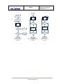
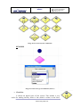
Flow diagram for sending and receiving data .......................................... 69
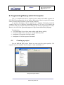
6. Programming Moway with C18 Compiler ............................................................. 71
6.1. Creating a project ............................................................................................. 71
6.2. First program in C18 ........................................................................................ 75
6.3. Libraries ........................................................................................................... 79
6.3.1. mOway´s sensors library in C18 .................................................................. 79
6.3.1.1.
Description ............................................................................................... 79
6.3.1.2.
Functions .................................................................................................. 80
6.3.2. mOway´s motor library C18 ........................................................................ 89
6.3.2.1.
Description ............................................................................................... 89
6.3.2.2.
Functions .................................................................................................. 89
6.3.3. BZI-RF2GH4 library in C18 ........................................................................ 96
6.3.3.1.
Description ............................................................................................... 96
6.3.3.2.
Functions .................................................................................................. 96
6.3.3.3.
Flow diagram for sending and receiving data ........................................ 102
7. mOwayGUI programming.................................................................................... 103
7.1. Creating a Project ........................................................................................... 103
7.2. First programme in mOwayGUI .................................................................... 103
7.3. mOwayGUI .................................................................................................... 110
7.3.1. Modules ...................................................................................................... 110
7.3.2. Conditionals ............................................................................................... 121
7.3.3. Start and End .............................................................................................. 133
7.3.4. Arrow ......................................................................................................... 133
7.3.5. Erase Arrow................................................................................................ 134
7.3.6. Subroutines ................................................................................................. 134
7.3.7. Recording ................................................................................................... 134
8. Moway RC Center ................................................................................................ 135
8.1. Description of the mOway RC Center ........................................................... 136
8.1.1. RF configuration ........................................................................................ 136
8.1.2. Radio control .............................................................................................. 137
8.1.3. LED ............................................................................................................ 137
8.1.4. Speaker ....................................................................................................... 137
8.1.5. Info ............................................................................................................. 137
8.1.6. Sensor status ............................................................................................... 137
8.1.7. Keyboard control ........................................................................................ 137
www.moway-robot.com
MOWAY
Title: mOway User Manual
Rev: v2.1.0 – June 2010
Page 5 of 137
1. Prologue
The dawning of a new era; the era of the minirobots. Increasingly more mobile
robotics applications enter our daily life. We can currently find robots which help us
with simple tasks like cleaning household floors, mowing the lawn or keeping the
swimming pool clean. As technology keeps improving, these small devices which blend
mechanics, electronics and software are performing more and more complex tasks*.
They are slowly introducing themselves into our lives in a useful manner and reducing
the burden of unpleasant jobs.
It’s not too far-fetched to think that the revolution which took place in the IT or
telecommunications fields will be repeated with robotics in the next decade. Enough
technology is currently available to manufacture these devices and society is also ready
to receive them in the market. Yet, a specific catalyst is needed to start this revolution.
People also need to be ready and prepared to identify in what fields microrobotics may
have an opportunity and which new applications may be interesting to implement.
Up till now processors weren’t able to move. But today things have changed.
Software is one of the fundamental elements in the world of mobile robotics. The main
difference between developing a program for these robots and running it with a personal
computer is interaction with the environment. The environment isn’t changing randomly
in PC applications, so decision making and programming are simplified. On the other
hand, when running commands for a minirobot application usually the result is
unknown, therefore algorithms have to consider situations with a wider range of
possibilities, some of them unexpected.
The mOway robots are tools specifically designed for teaching and research. Their
purpose is to bring the world of autonomous robots closer to the teaching centers.
mOway’s main purpose is to be a useful tool for those who are being introduced
for the first time to the world of the minirobots as well as for those who are already
experienced and wish to perform complex collaborative robotic applications.
mOway aims to stimulate enthusiasm for this new and exciting branch of
engineering in a prompt and enjoyable way through the practical exercises included in
this manual.
- An easy and entertaining way to learn.
- This book’s purpose: to be mOway’s Manual and not a comprehensive book on
minirobotics.
This manual has been implemented to assist learning how to use mOway. It
provides some basic notions on using mOway and its functions in a quick and clear
manner.
www.moway-robot.com
MOWAY
Title: mOway User Manual
Rev: v2.1.0 – June 2010
Page 6 of 137
This manual is divided in two parts. The first part includes a description of the
elements which form part of the robot and their functioning. The second part of the
manual includes a series of practical exercises that can be executed with mOway.
www.moway-robot.com
MOWAY
Title: mOway User Manual
Rev: v2.1.0 – June 2010
Page 7 of 137
2. What is mOway?
mOway is an autonomous programmable small robot designed mainly to perform
practical minirobotics applications.
It provides a perfect hardware platform for those wishing to take their first steps
within the world of mobile robots as well as for those who have already worked with
minirobots and want to develop more complex applications.
The mOway robot is equipped with a series of sensors which aid it to move in a
real environment. It also includes a drive unit which allows it to move over smooth
terrain commanded by a I2C communications bus. All these peripherals are connected
to a microcontroller responsible for governing the robot.
This small robot incorporates I2C/SPI expansion bus options. As an example, a
wireless communications module, a video camera or a prototype card can be connected
to it as well as any other device considered interesting to perform a certain task.
mOway’s external design is very compact, intended to move with grace and style
avoiding standstills due to obstacles or corners. This small mobile device has been
fittingly called a “pocket robot”.
mOway is a perfect tool for those who want to both learn and teach minirobotics.
The user will be pleasantly surprised by the speed in achieving results even if this is the
first time he/she comes into contact with mobile robots.
www.moway-robot.com
Title: mOway User Manual
Rev: v2.1.0 – June 2010
Page 8 of 137
MOWAY
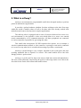
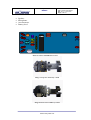
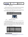
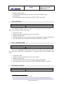
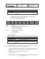
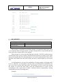
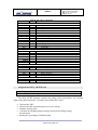
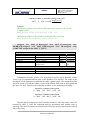
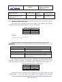
3. Robot mOway
This chapter describes each of the parts that constitute the mOway. It is important
to highlight that it is not necessary to know the total functioning of the robot to be able
to program it, at least not at the level of detail explained here.
The following elements are to be found inside mOway:
•
•
•
•
•
Processor
Drive system
Sensors and indicators group
Power supply system
An expansion connector
Gear
Encoder
IR
_R
X_
R
LINE_RX_R
BATTERY
METER
TEMP
MIC
IR_R
X
PIC18f86j50
LED_
BRAKE
PIC16F687
_R
LINE_RX_R
FRON
T_LED
LINE_TX
LINE_RX_L
LED_
GREEN
LIGHT_
SEN
LED_
RED
X_L
IR_R
L
X_
_R
IR
LINE_TX
ACCELE
E
N
G
I
N
E
FREE
PAD
E
X
P
A
N
S
I
O
N
H Bridge
LED_
BRAKE
SPEAKER
LINE_RX_R
LINE_TX
Encoder
E
N
G
I
N
E
Gear
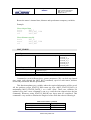
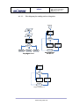
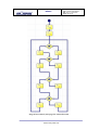
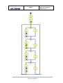
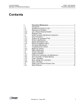
Image 1. Diagram of mOway’s parts
3.1.
Processor
mOways are governed by a 4 Mhz PIC18F87J50 microcontroller manufactured by
Microchip Technologies. All the peripherals distributed throughout the whole robot are
connected to its input/output ports. Some of them need a digital input or output, others
need an analog input or output and others, instead, are controlled by one of the I2C/SPI
communication buses. The table below describes how the microcontroller pins are
distributed.
www.moway-robot.com
MOWAY
Title: mOway User Manual
Rev: v2.1.0 – June 2010
Page 9 of 137
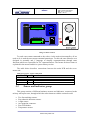
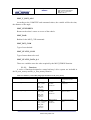
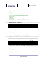
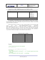
Table 1. PIC-sensors connections
Pin PIC
PORTA
RA0
RA1
RA2
RA3
RA5
PORTB
RB1
RB2
RB3
RB5
RB6
PORTC
RC7
PORTD
RD1
RD4
RD5
RD6
RD7
PORTE
RE5
PORTF
RF5
RF6
PORTH
RH5
RH6
RH7
PORTJ
RJ6
RJ7
3.2.
I/O
Sensor
I
I
I
I
I
Light
Central left infrared receiver
Right line sensor receiver
Side left infrared receiver
Left line sensor receiver
I
I
O
O
O
First interruption of the accelerometer
Second interruption of the accelerometer
Speaker
Top red LED
Top green LED
O
Front LED
O
I
O
O
I
Line sensors transmitter
SDO signal for the SPI communication (accelerometer)
SDI sinal for the SPI communication(accelerometer)
Clock sinal for the SPI communication(accelerometer)
Chip Select for the SPI communication(accelerometer)
O
Brake LED
I
I
Side right infrared receiver
Central right infrared receiver
I
I
I
Tempreature sensor
Battery measurer
Microphone
O
I/O
Infrared transmitter
Free pad
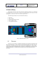
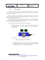
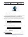
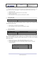
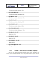
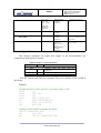
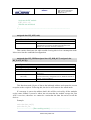
Drive system
To be able to move the mOway uses a double servo-motor group. It includes both
an electronic part and a mechanical one. The electronic part is mainly in charge of
controlling the motor’s speed and the mechanical part allow the mOway to move
unhindered over different terrains with adequate power.
www.moway-robot.com
MOWAY
Title: mOway User Manual
Rev: v2.1.0 – June 2010
Page 10 of 137
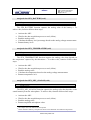
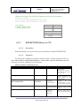
Image 2. Drive system: electronic and mechanical
The servo-motor group includes different features:
1. Speed control: controls the speed of each motor.
2. Time control: controls the time for each command with a 100 ms precision.
3. Traveled distance control: Controls the distance traveled by each command
with a precision of 1 mm aprox.
4. General speedometer: counts distances traveled since the initial command.
5. Angle control: controls the angle when the mOway rotates.
The microcontroller sends the I2C command to the drive system that controls the
motors and therefore releasing the main microcontroller so it can carry out other tasks.
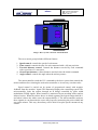
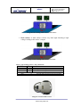
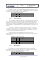
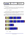
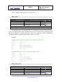
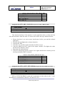
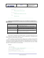
Speed control is carried out by means of proportional control with negative
feedback from the encoders’ signal. The illustration displays the controlling system. The
microcontroller feeds the motors through an H bridge controlled by pulse width
modulation (PWM) signals. Wheel rotation is monitored by an encoding sticker and an
infrared sensor. When the sticker shows its black segment, the logical output shall be 1
and when it shows the white sector the output shall be 0. The microcontroller analyzes
these signals (it can determine the exact wheel speed by measuring the pulse width) and
acts on the motors. This way, the mOway will be able to keep the speed constant on any
surface.
www.moway-robot.com
MOWAY
Title: mOway User Manual
Rev: v2.1.0 – June 2010
Page 11 of 137
Image 3. Motor control
To send a movement command to the robot, via the main microcontroller, all we
need to do is send the movement command parameters. To this end some libraries were
designed in assembly and C language to simplify communications through some
functions which are responsible for I2C communications. The format for these frames is
explained in the motors and drive system library section.
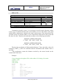
The table below describes connections between the main PCB and the servomotor unit.
Table 2. Processor - motor connections
Pin PIC
PORTE
RE0
I2C
RE1
I2C
RE7
I
3.3.
I/O
Sensor
I2C clock
I2C data
END_COMAND line
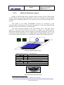
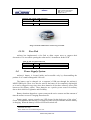
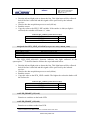
Sensor and indicators group
This group consists of different luminous sensors and indicators, connected to the
mOway microprocessor, through which the robot interacts with the external world:
•
•
•
•
•
•
Two line tracking sensors.
Four obstacle detection sensors.
A light sensor.
An expansion connector.
Four LED diodes.
Temperature sensor.
www.moway-robot.com
MOWAY
•
•
•
•
Title: mOway User Manual
Rev: v2.1.0 – June 2010
Page 12 of 137
Speaker.
Microphone.
Accelerometer.
Battery level.
Image 4. Sensors and indicators group
Image 5. Top-view of mOway´s PCB
Image 6. Down-view of mOway´s PCB
www.moway-robot.com
MOWAY
3.3.1.
Title: mOway User Manual
Rev: v2.1.0 – June 2010
Page 13 of 137
Line sensors
The line tracking sensors are two reflection optocouplers mounted on the top front
part of the robot. They use infrared light reflection to detect the color of the terrain at
the point where the robot is.
These two sensors are connected to two microcontroller analog ports so strong
terrain contrasts, like white lines on black backgrounds, can be detected. They are also
capable of distinguishing different tones.
The Vishay CNY70 sensor has a compact construction where the emitting light
source and the detector are arranged in the same direction to be able to detect by using
the reflective IR beam the light reflected in the terrain.
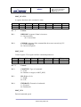
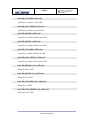
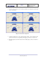
In the images below the three possible cases can be observed:
1. Clear surface: A white surface reflects all the infrared light and
therefore we obtain a low voltage reading at the transistor’s output when
in regular mode.
Image 7. Line tracking sensor on a clear surface.
•
1
Colored surface: A colored surface reflects part of the emitted light
obtaining an intermediate voltage at the microcontroller’s analog
channel input. This way colors are easily identified1.
Due to CNY70 tolerance two different sensor can differ.
www.moway-robot.com
MOWAY
Title: mOway User Manual
Rev: v2.1.0 – June 2010
Page 14 of 137
Image 8. Line tracking sensor on a colored surface.
1. Dark surface: A dark surface reflects very little light obtaining a high
voltage reading at the sensor’s output.
Image 9. Line tracking sensor on a dark surface.
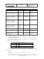
Table 3. Line tracking sensors - PIC connections
Pin PIC
PORTA
RA2
RA5
PORTD
RD1
I/O
Sensor
I
I
Right line tracking sensor receiver
Left line tracking receiver
O
Left and right line tracking sensors transmitter
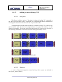
Image 10. Location of line sensors
www.moway-robot.com
MOWAY
3.3.2.
Title: mOway User Manual
Rev: v2.1.0 – June 2010
Page 15 of 137
Obstacle detection sensors
Similar to line tracking sensors, obstacle detection sensors also use infrared light
to detect objects located in front of the mOway. The sensor includes two infrared lightemitting source (Kingbright KPA3010-F3C) and four receivers placed on both sides of
mOway.
The output of the Sharp PT100F0MP receivers are connected to the
microcontroller’s analog inputs so it can detect the presence of any object (digital mode)
and also measure how far away it is (analog mode)2.
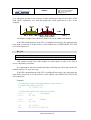
The sensor functions similarly to the line tracking sensor. The light emitter
generates a 70us pulse which allows the receiver to capture any obstacle using a
filtering and amplifying stage. Once the signal is processed electronically, the PIC can
measure it by means of the ADC or as a digital input. The digital distance range is close
to 3cm and a bright environment is recommended to enhance infrared light reflection.
Image 11. Obstacle detection sensor
Table 4. Shock-proof sensor - PIC connections
Pin PIC
PORTA
RA1
RA3
PORTF
RF5
RF6
PORTJ
RJ7
I/O
Sensor
I
I
Central right infrared receiver
Side left infrared receiver
I
I
Side right infrared receiver
Central left infrared receiver
O
Infrared transmitter
Image 12. Location of Obstacle Sensor
2
Due to tolerance two different sensors can differ from each other.
www.moway-robot.com
Title: mOway User Manual
Rev: v2.1.0 – June 2010
Page 16 of 137
MOWAY
3.3.3.
Light sensor
This sensor allows mOway to recognize the light intensity that enters through a
small half moon-shaped opening on the top part of the chassis. Since it is facing forward
it enables it to detect where the light source is located and to act accordingly.
The output of the AVAGO APDS-9002 sensor is connected to the analog port of
the microcontroller so that with a simple reading of the ADC we can register the light
intensity level and any change in intensity levels based on the last reading3.
Table 5. PIC - light sensor connection
Pin PIC
I/O
PORTA
RA0
Sensor
I
Luz
Image 13. Location of Light Sensor
3.3.4.
Expansion connector
This connector allows the mOway to connect with any commercial modules or
electronic circuits the user may choose.
As shown in the above table, it is possible to connect commercial SPI devices. On
the other hand, the RF BZI-RF2GH4 module available in the market is totally
compatible with mOway and with specific libraries. This module enables the mOway to
communicate with other robots and with a PC via the RFUsb. With this module it is
possible to create complex collaboration applications without having to worry about
complicated wireless communications.
Table 6. Expansion connector connections
Pin Expa
Pin1
Pin2
Pin3
Pin4
Pin5
Pin6
Pin7
Pin8
3
I/O
PIC
O
O
I/O /PMD3/AN12/P3C
/C2INC
I/O/PMA5/AN7/C2INB
I/O /SCK1/SCL1
I/O /SDO1/C2OUT
I/O /SDI1/SDA1
I/O/INT
Vcc 3.3v
GND
RH4
RF2
RC3
RC5
RC4
RB0
Top two-color LED has to be switched off to have a valid measure.
www.moway-robot.com
MOWAY
Title: mOway User Manual
Rev: v2.1.0 – June 2010
Page 17 of 137
Image 14. RF modules into expansion connector.
3.3.5.
Temperature sensor
mOway has installed as a temperature measurer an NTC thermistor from Murata,
a semiconductor whose electrical variable resistance decreases as temperature increases.
The sensor is located in the front part of the robot, very close to obstacle sensor.
The thermistor is connected to the analog port of the microcontroller so that with a
simple reading of the ADC it is possible to get the temperature value in that moment
and notice any change in it since the last reading4.
Table 7. PIC-Temperature sensor connection
Pin PIC
I/O
PORTH
RH5
3.3.6.
Sensor
I
Temperature sensor
Speaker
The CMT-1102 speaker from CUI INC directly connected to the microcontroller,
is capable to play tones from 250 Hz to 65 KHz.
Table 8. PIC-Speaker connection
Pin PIC
PORTB
RB3
3.3.7.
I/O
Sensor
O
Speaker
Microphone
The CMC-5042PF-AC microphone from CUI INC enables the robot to detect
sounds from 100 Hz to 20 KHz.
4
Temperature measured by the sensor can be 5ºC higher than external temperature.
www.moway-robot.com
MOWAY
Title: mOway User Manual
Rev: v2.1.0 – June 2010
Page 18 of 137
The output is directly connect to an analog input of the microcontroller so that it is
capable to detect not only if there is sound or not (digital mode) but also the intensity of
the sound with a simple reading of the ADC (analog mode).
Table 9. PIC-Microphone connection
Pin PIC
I/O
PORTH
RH7
3.3.8.
Sensor
I
Microphone
Accelerometer
An accelerometer is a device that measures acceleration and the gravity induced
forces: the movement and rotation. There are many types of accelerometers, most of
them based on piezoelectric crystals, but their size is too big. Because of that, it was
tried to design a small device in the field of microelectronics, which might improve the
applicability. Then, the MEMS (Microelectromechanical Systems) accelerometers were
created.
An easy way to create an accelerometer is measuring changes in a capacitor.
Capacitors can work as sensors or as actuators. In the case of mOway, it is a capacitive
accelerometer, which consists of two capacitors displaced in differential mode whose
electrical capacity changes as the acceleration varies.
By measuring X, Y, Z axes of the MMA7455L accelerometer from
FREESCALE Semiconductor, it is possible to know if mOway is correctly positioned,
inverted or tilted.
Table 10. PIC-Accelerometer connection
Pin Acce
I/O
Pin7
Pin8
Pin9
Pin12
Pin13
Pin14
3.3.9.
PIC
I
I
I
I
O
O
RD7
RB1
RB2
RD4
RD5
RD6
Battery level
The robot has a LiPo cell battery rechargeable. For proper operation of the
microcontroller, the battery is connected to one of its analog inputs through a splitter.
Thus, with a reading of the ADC battery level can be measured.
Table 11. PIC-Battery level connection
Pin PIC
I/O
Sensor
PORTH
www.moway-robot.com
MOWAY
RH6
3.3.10.
I
Title: mOway User Manual
Rev: v2.1.0 – June 2010
Page 19 of 137
Battery level
Front LED
The front LED is a white LED placed on the front side of mOway. The output of
the OSRAM LW A6SG LED is connected to a digital output of the microcontroller.
Table 12. PIC - front LED connections
Pin PIC
I/O
PORTC
RC7
3.3.11.
Sensor
O
Front LED
Top two-color LED
This double indicator and the light sensor share the same opening on the top part
of the robot. They are connected to two microcontroller digital outputs5.
Table 13. PIC-Top LED connection
Pin PIC
PORTA
RA4
PORTB
RB6
I/O
Sensor
O
Top red LED
O
Top green LED
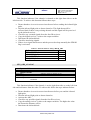
Image 15. Robot with Front LED and red LED switched on
3.3.12.
Brake LED
The brake LED is double indicator placed on the back side of mOway. The output
is connected to one digital outputs of the microcontroller.
5
Please note that since they share the same opening as the light sensor it is fundamental to switch
them off when wanting to perform a light intensity reading.
www.moway-robot.com
MOWAY
Title: mOway User Manual
Rev: v2.1.0 – June 2010
Page 20 of 137
Table 14. PIC- Brake LED connection
Pin PIC
I/O
PORTE
RE5
Sensor
O
Brake LED
Image 16. Brake LED location. Switch on green LED.
3.3.13.
Free Pad
mOway has implemented a free Pad to allow expert users to connect their
electronics. It is accessible opening the robot and it´s located near brake LED6.
Table 15. PIC-free Pad connection
Pin PIC
PORTJ
RJ7
3.4.
I/O
Sensor
I/O
Free Pad
Power Supply System
mOway’s battery is located inside and accessible only by disassembling the
product. It is a small rechargeable LiPo cell.
The battery can be charged via a computer’s USB port through the mOway’s
MINI-USB-B port. There is no need to wait for the battery to be completely discharged,
as it can be plugged in any time since these batteries do not have memory effect (also
known as lazy battery effect). These batteries are a perfect power source for mOway
due to their small size, lightness and flexibility.
Battery duration depends to a great extent on the active sensors and the amount of
time the motors are used. Charging lasts about 2h.
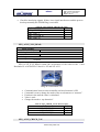
Power supply system controls two LED located in the back part of the robot7.
Green LED indicates that mOway is switched on and red LED indicates that the battery
is charging. When the battery is full red LED will switch off8.
6
7
Advanced users only
These LEDs can´t be controlled by the user.
www.moway-robot.com
MOWAY
Title: mOway User Manual
Rev: v2.1.0 – June 2010
Page 21 of 137
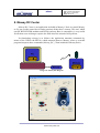
Image 17. Charging (red) and switched on (green)
3.5.
RF module and RFUsb9
RF module allows communicate with other mOways or with PC using RFUsb.10.
Image 18. RF module
RF module is connected in expansion connector and it is very easy to use with
mOwayGUI. The best way to start working with the module is using an example project
provided in mOwayPack.
8
This LED can swap between on and off when the battery is fully charge because there is energy
consumption when mOway is plugged.
9
Available in some packs
10
Available in some packs
www.moway-robot.com
Title: mOway User Manual
Rev: v2.1.0 – June 2010
Page 22 of 137
MOWAY
Image 19. RFUsb
The BZI-RF2GH4 radio-frequency communications module is based on the
nRF24L01 transceptor manufactured by “Nordic Semiconductors”. This integrated
circuit has been fitted with all the logic required to establish wireless bidirectional
communications with acknowledgement of receipt. Communications with the
microcontroller is made via an SPI bus.
The main characteristics of the BZI-RF2GH4 module are as follows:
•
•
•
•
•
Low consumption.
Working frequency: 2.4GHz,
Transmitting power between-18 and 0 dBm,
Transmission speed between 1 and 2 Mbps,
128 in transmission channels selectable by the SPI bus.
In addition to the CI nRF24L01, the BZI-RF2GH4 is also fitted with all the
associated electronics for its correct operation plus a microstrip antenna on the same
board with the impedance adaptation network. In this way the user can forget
completely about the hardware required to implement the radio part of his application.
As interface, the device has four pins available for the SPI bus, two more pins for
controlling the module and another two for the supply.
In order to facilitate the handling of the module, a number of libraries have been
developed to simplify and shorten the development time of wireless applications with
these modules.
3.5.1.
Technical specifications
Table 16. Maximum Ratings
Parameter
Vdd
Vss
Data input voltage
Data output voltage
Min
-0.3
Max
3.6
0
-0.3
5.25
Vss-Vdd Vss-Vdd
www.moway-robot.com
Unit
V
V
V
V
Title: mOway User Manual
Rev: v2.1.0 – June 2010
Page 23 of 137
MOWAY
Power dissipation
Operating temperature
Storage temperature
-40
-40
60
+85
+125
mW
ºC
ºC
Value
1.9
3.6
0
2000
11.3
12.3
900
8
-40 a +85
Unit
V
V
dBm
Kbps
mA
mA
nA
Mhz
ºC
Table 17. Specifications BZI-RF2GH4
Parameter
Minimum supply voltage
Maximum supply voltage
Maximum power output
Maximum transmission speed
Current in transmission mode @ 0dbm power output
Current in reception mode@ 2000kbps
Current in Power Down mode
Maximum frequency of the SPI bus
Temperature range
Table 18. Pinout BZI-RF2GH4
Pins
Vcc
Vss
CE
CSN
Nº
1
2
3
4
Description
Supply voltage of the module
GND
Chip Enable
Chip Select of the SPI
SCK
SDI
SDO
IRQ
5
6
7
8
SPI bus clock
Data input to the RF module of the SPI bus (MOSI)
Data output from the RF module of the SPI bus(MOSI)
Output interruption
Image 20. Module layout
www.moway-robot.com
MOWAY
Title: mOway User Manual
Rev: v2.1.0 – June 2010
Page 24 of 137
4. First Steps
4.1.
mOway Pack installation
In mOwayPack (available in the webpage or in the installation CD) you will find
the software, mOway´s libraries, test programs and documentations.
Following setup steps you will have all the resources:
•
Beginner’s and User manual.
o Beginner’s manual includes all you need to start working with mOway.
o User manual contains detailed description of the robot.
mOwayGUI software.
o This software controls all aspects of the robot: program download,
battery charge control, radio control, RFUsb11 management and C or
assembler programs download.
Reference projects in assembler and C.
o Example projects to start working with mOway easily.
RFUsb Driver
o Driver for RFUsb12 that allows the communication between robots and
PC.
•
•
•
Image 21. CD
11
12
Module not available in all kits
Module not available in all kits
www.moway-robot.com
Title: mOway User Manual
Rev: v2.1.0 – June 2010
Page 25 of 137
MOWAY
4.2.
Download a program to mOway
Download process is always executed in mOwayGUI. This application can
download to the robot mOwayGUI, assembler (compiled with Mplab o gputils) and C
(C18 compiler) projects.
Steps to download a program to mOway:
• Connect mOway to the PC through USB. The robot doesn´t need any
driver.
• Open mOwayGUI application.
• Open or create a project in mOwayGUI, or import a .HEX file from
assembler or C project.
• Click download bottom. If a .HEX file has been imported the download
progress will start automatically.
• Disconnect the robot and check the project.
mOwayPack provide 8 compiled projects: 3 to check sensors, 3 to check the
drive system and 2 programs that are explained in the next section.
Project to check sensors:
•
•
•
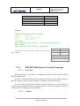
ASM_SEN_01: Assembler software to check sensors. Obstacle sensors are
checked and if an object is detected LEDs and speakers are switched on. This
project uses absolute lib_sen_moway.inc library.
ASM_SEN_02 : Assembler software to check sensors. Obstacle sensors are
checked and if an object is detected LEDs and speakers are switched on. This
project uses relocatable lib_re_sen_moway.inc library.
C_SEN_01 : C18 software to check sensors. Obstacle sensors are checked and if
an object is detected LEDs and speakers are switched on.
Project to check drive system:
•
•
•
ASM_MOT_01: Assembler software to
movements of mOway are executed.
lib_mot_moway.inc library.
ASM_MOT_02: Assembler software to
movements of mOway are executed.
lib_re_mot_moway.inc library.
C_MOT_01: C18 software to check drive
mOway are executed.
check drive system. Different
This project uses absolute
check drive system. Different
This project uses relocatable
system. Different movements of
Projects to check RF module:
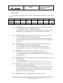
•
ASM_RF_01: Assembler software to check RF module. Sends data to
channel 0x40 and address 0x02 every 2 sec. This project uses absolute
lib_rf2gh4.inc library.
www.moway-robot.com
MOWAY
•
•
•
•
•
Title: mOway User Manual
Rev: v2.1.0 – June 2010
Page 26 of 137
ASM_RF_02: Assembler software to check RF module. Sends data to
channel 0x40 and address 0x02 every 2 sec. This project uses relocatable
lib_re_rf2gh4.inc library.
ASM_RF_03: Assembler software to check RF module. Makes robot work
as a repeater. Reception without interruption. This project uses absolute
lib_rf2gh4.inc library.
ASM_RF_04: Assembler software to check RF module. Makes robot work
as a repeater. Reception without interruption. This project uses relocatable
lib_re_rf2gh4.inc library.
C_RF_01: C18 software to check RF module. Sends data to channel 0x40
and address 0x02 every 2 sec.
C_RF_02: C18 software to check RF module. Makes robot work as a
repeater. Reception without interruption.
First projects:
•
•
mOway_first_project_ASM: Assembler project explained in this manual.
mOway avoids obstacles rotating 180º.
mOway_first_project_C18: C18 project explained in this manual. mOway
avoids obstacles rotating 180º.
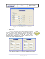
4.3.
RFUsb instalation
• This is a device that allows to communicate the PC and mOway.
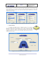
A driver that it´s included in mOwayPack is required:
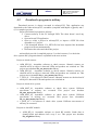
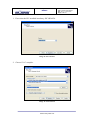
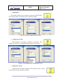
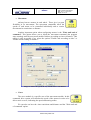
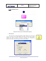
• The first time the RFUsb is connected, the PC will detect it as a new
device and an “Assistant for new hardware found” message will be
displayed. Select the No,not this time option.
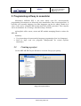
• In the following window select the recommended option: Install software
automatically.
Image 22. Driver installation Wizard
www.moway-robot.com
MOWAY
•
Title: mOway User Manual
Rev: v2.1.0 – June 2010
Page 27 of 137
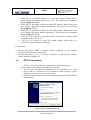
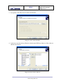
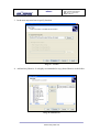
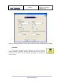
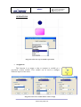
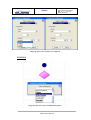
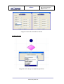
Now the installation process will begin.
Image 23. Windows xp driver installation
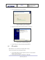
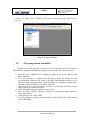
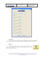
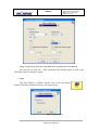
•
Assistant will then indicate that the hardware is installed.
Image 24. Driver installed in Windows xp
•
4.4.
Check if Moway’s software has detected the RFUsb
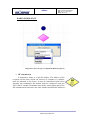
RF modules
RF modules are very useful tool to introduce RF concept.
These are the steps to start working with them:
• Connect RF modules into the expansion connector. Check that the
module is fully connected.
• Connect the robot to the PC through the USB cable.
www.moway-robot.com
MOWAY
•
•
•
•
•
Title: mOway User Manual
Rev: v2.1.0 – June 2010
Page 28 of 137
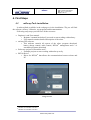
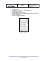
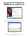
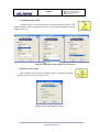
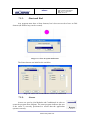
Open mOwayGUI.
Open mOway_RF_send project included in the pack.
Click the Program bottom.
Disconnect and switch the robot on.
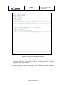
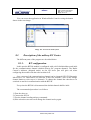
Configure RFUsb module using RF window of mOwayGUI with cannel
0x00 and address 0x01.
• Check receiving data in mOwayGUI.
Image 25. RF window
www.moway-robot.com
MOWAY
Title: mOway User Manual
Rev: v2.1.0 – June 2010
Page 29 of 137
5. Programming mOway in assembler
Microchip’s MPLAB IDE is the most widely used PIC microcontroller
programming environment (as Microchip also manufactures these microcontrollers). It
basically uses assembly language, but other languages can also be added. Thanks to it
source code can be compiled and hexadecimal files (.HEX) generated. This compiler
can be downloaded, free of charge, from Microchip’s Website.
mOwayPack offers sensor, motor and RF module managing libraries written for
MPLAB.
Summary:
• Very interesting to learn assembly language programming (low level language).
• Ideal for large code size programs. Indispensable for critical response
timeframes.
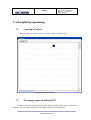
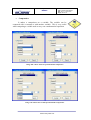
5.1.
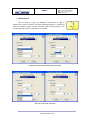
Creating a project
Use the MPLAB IDE Project Wizard to create the first project quickly.
Image 26. Project Wizard
www.moway-robot.com
MOWAY
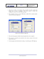
1. First select the PIC installed in mOway: PIC18F86J50
Image 27. PIC selection
2. Then select the assembly tool: MPASM.
Image 28. Tool selection
www.moway-robot.com
Title: mOway User Manual
Rev: v2.1.0 – June 2010
Page 30 of 137
MOWAY
Title: mOway User Manual
Rev: v2.1.0 – June 2010
Page 31 of 137
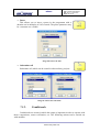
3. In step three enter the project’s name and location.
Image 29. Select name and folder
4. In the next step the mOway libraries which control different features of the robot are
added to the project.
Imagen 30. Select mOway libraries
www.moway-robot.com
MOWAY
Title: mOway User Manual
Rev: v2.1.0 – June 2010
Page 32 of 137
5. With the steps above the project will now be created, the next step is to create a
.ASM file for the source code.
Image 31. Wizard ends
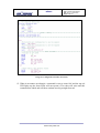
6. The next step is to open the project and create a new file (New File) saving it in the
same folder of the project as Main.asm. This will be our source file.
Image 32. .ASM creation
www.moway-robot.com
MOWAY
Title: mOway User Manual
Rev: v2.1.0 – June 2010
Page 33 of 137
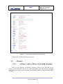
7. Finally, the source file is added to the project accessing Project/Add Files to
Project…
Image 33. Project with .ASM
5.2.
First program in assembler
To generate the first program a project has to be created first (previous chapter).
This first basic program will enable the mOway to avoid obstacles. (Absolute code)
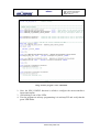
1. First the list p=18F86J50 PIC installed in mOway has to be added to the
Main.ASM file.
2. It is also necessary to include into the project folder the library for this
microcontroller which can be found at the MPLAB installation directory or in
mOway’s pack testing programs. Once this library is copied to the folder enter:
#include "P18F86J50.INC" in the Main.ASM file.
3. The next step is to add the starting (0x102A) and resetting (0x1000) vectors,
and to include the mOway libraries.
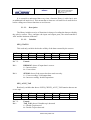
4. INIT and MAIN labels are added to create a loop.
5. Next, the SEN_CONFIG function is called to configure the microcontroller’s
inputs and outputs.
6. Add winking to one of the LEDs.
7. Test the program on mOway programming it in mOwayGUI and verify that the
green LED blinks.
www.moway-robot.com
MOWAY
Title: mOway User Manual
Rev: v2.1.0 – June 2010
Page 34 of 137
Image 34. First program: configuration and LED
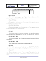
8. To detect obstacles call up the SEN_OBS_DIG function with OBS_CENTER_L
parameter, in infinite loop, which will inform of the presence of an obstacle
through the SEN_OBS variable.
9. If it detects an obstacle the front LEDs light up.
10. Test the program on mOway and verify that the LEDs switch on when an object
is placed close to the front part of the mOway.
www.moway-robot.com
MOWAY
Title: mOway User Manual
Rev: v2.1.0 – June 2010
Page 35 of 137
Image 35. First program: detecting obstacles
11. We then add movement to the robot: unrestricted straight command until it
encounters an obstacle.
12. lib_mot_asm.inc is added to the project.
13. MOT_CONFIG is called to be able to use Diver system.
14. Go straight on the first time.
www.moway-robot.com
MOWAY
Title: mOway User Manual
Rev: v2.1.0 – June 2010
Page 36 of 137
Image 36. Configuration and first movement
15. When it encounters an obstacle a command is sent to rotate 180º and the top red
LED lights up (the front LEDs will not operate). The robot will wait until this
command has ended and will then continue moving straight forward.
www.moway-robot.com
MOWAY
Title: mOway User Manual
Rev: v2.1.0 – June 2010
Page 37 of 137
Image 37. . First program: detecting obstacles moving
This project is included in the mOway pack.
5.3.
Libraries
5.3.1.
mOway´s sensors library in assembly language
There are two libraries in assembly language which can be included in any
mOway project and allow the user to control the sensors with ease. Both are identical
except that one of them can relocate the code and the variables (using the MPLAB IDE
projects).
www.moway-robot.com
Title: mOway User Manual
Rev: v2.1.0 – June 2010
Page 38 of 137
MOWAY
It is essential to understand that every time a function library is called up it uses
an additional call stack level. This means that at least two call stack levels must be free
before calling one of these functions to avoid errors.
5.3.1.1.
Description
The library includes a series of functions in charge of reading the data provided by
the robot’s sensors. They configure the input and output ports, the microcontroller’s
ADC and the luminous indicators.
5.3.1.2.
Variables
SEN_STATUS
This read-only variable checks the validity of the data returned by the sensors.
Bit7
Unused
-
Bit6
Unused
-
Bit5
Unused
-
Bit4
Unused
-
Bit3
Unused
-
Bit2
Unused
-
Bit1
Bit0
DWRONG SENOK
Bit 7-2:
Unused
Bit 1:
DWRONG: shows if input data is correct.
1 = Incorrect data.
0 = Correct data.
Bit 0:
SENOK: shows if the sensor has been read correctly.
1 = Correct reading. Valid output data.
0 = Incorrect reading. Invalid output data.
SEN_ACCE_TAP
Read-only variable that shows if SEN_CHECK_ACCE_TAP function detects one
or two taps.
Bit7
Unused
Bit 7-2:
Bit 1:
Bit6
Unused
-
Bit5
Unused
-
Bit4
Unused
-
Bit3
Unused
-
Bit2
Unused
-
Unused
TAP_TAP: shows if double tap is detected
1 = Double Tap detected
0 = Double Tap not detected
www.moway-robot.com
Bit1
Bit0
TAP_TAP TAP
Title: mOway User Manual
Rev: v2.1.0 – June 2010
Page 39 of 137
MOWAY
Bit 0:
TAP: shows if tap is detected
1 = Tap detected
0 = Tap not detected
SEN_CHECK_OBS
This write-only variable shows which sensor must be read by obstacle functions.
Table 19. Allowed values for SEN_CHECK_OBS
Define
OBS_CENTER_L
OBS_SIDE_L
OBS_CENTER_R
OBS_SIDE_R
Value
0
1
2
3
SEN_CHECK_ACCE
This write-only variable shows
SEN_ACCE_XYZ_READ function.
which
axis
must
be
read
by
Table 20. Allowed values for SEN_CHECK_ACCE
Define
ACCE_CHECK_X
ACCE_CHECK_Y
ACCE_CHECK_Z
Value
0
1
2
SEN_CHECK_LINE
This write-only variable shows which sensor must be read by line functions.
Table 21. Allowed values for SEN_CHECK_LINE
Define
LINE_L
LINE_R
Value
0
1
SEN_SPEAKER_ON_OFF
This write-only variable shows if speaker have to turn on, turn off or play an
amount of time.
www.moway-robot.com
MOWAY
Title: mOway User Manual
Rev: v2.1.0 – June 2010
Page 40 of 137
Table 22. Allowed values for SEN_SPEAKER_ON_OFF
Define
SPEAKER_OFF
SPEAKER_ON
SPEAKER_TIME
Value
0
1
2
SEN_LIGHT_P
This variable records the percentage of light reaching the light sensor. It is
updated every time the SEN_LIGHT function is called.
SEN_BATTERY_P
This variable records the percentage of the battery level. It is updated every time
the SEN_BATTERY function is called.
SEN_TEMPERATURE_C
This variable records the value of the temperature in ºC. It is updated every time
the SEN_TEMPERATURE_C function is called.
SEN_MIC
This variable records the value of the microphone. The data will be digital or
analog depending on the updating function: SEN_MIC_DIG and SEN_MIC_ANALOG.
SEN_SPEAKER_FREQ
This variable records the value of the frecuency, between 250 Hz and 65 KHz, to
create the tone.
SEN_SPEAKER_TIME
These variable records the time the speaker must send the tone.
SEN_OBS
This variable stores the value of the obstacle sensor (SEN_CHECK_OBS). This
value is updated when SEN_OBS_DIG or SEN_OBS_ANALOG functions are called.
SEN_ACCE
This variable stores the value of the acceleration The axis is selected by
SEN_CHECK_ACCE. This value is updated when SEN_ACCE_XYZ_ functions is
called.
www.moway-robot.com
Title: mOway User Manual
Rev: v2.1.0 – June 2010
Page 41 of 137
MOWAY
SEN_ACCE_TAP
This variable records if mOway has been taped. It is updated every time the
SEN_ACCE_CHECK_TAP function is called up.
SEN_LINE
This variable stores the value of the line sensor (SEN_CHECK_LINE). This
value is updated when SEN_LINE_DIG or SEN_LINE_ANALOG functions are called.
5.3.1.3. Functions
A series of functions to control mOway’s sensors and LED diodes are included in
the lib_sen_moway and lib_re_sen_moway libraries.
Below is a brief description of each one of these function.
Table 23. ASM function summary
Name
Input variable
SEN_CONFIG
Output variable
Description
SEN_LIGHT
SEN_BATTERY
SEN_TEMPERATURE
-
SEN_LIGHT_P
Configured to use the
sensors.
Reads light sensor values.
-
SEN_BATTERY_P
Returns the battery level.
-
SEN_TEMPERATURE_C
SEN_MIC_ANALOG
SEN_MIC_DIG
-
SEN_MIC
Detects the temperature in
ºC.
Detects sound intensity.
-
SEN_MIC
SEN_OBS_DIG
SEN_SPEAKER_FREQ
SEN_SPEAKER_TIME
SEN_SPEAKER_ON_OFF
SEN_CHECK_OBS
SEN_OBS_ANALOG
SEN_CHECK_OBS
SEN_ACCE_XYZ_READ
SEN_CHECK_ACCE
SEN_SPEAKER
SEN_ACCE_CHECK_TAP
-
Detects if there is sound
or not.
Emits
tones
in
a
frequency between 250
Hz and 65 KHz.
Detects obstacles
-
SEN_OBS
SEN_STATUS
SEN_OBS
SEN_STATUS
SEN_ACCE
SEN_STATUS
SEN_ACCE_TAP
SEN_STATUS
SEN_LINE
SEN_STATUS
SEN_LINE
SEN_STATUS
-
-
-
Front LED on
-
-
Top red LED on
-
-
Top green LED on
-
-
Brake LED off
-
-
Front LED off
-
-
Top red LED off
-
-
Top green LED off
-
-
Brake LED blink
-
-
Front LED blink
-
-
Top red LED blink
-
-
Top green LED blink
-
SEN_LINE_DIG
SEN_CHECK_LINE
SEN_LINE_ANALOG
SEN_CHECK_LINE
LED_BRAKE_ON
LED_FRONT_ON
LED_TOP_RED_ON
LED_TOP_GREEN_ON
LED_BRAKE _OFF
LED_FRONT_OFF
LED_TOP_RED_OFF
LED_TOP_GREEN_OFF
LED_BRAKE _ON_OFF
LED_FRONT_ON_OFF
LED_TOP_RED_ON_OFF
LED_TOP_GREEN_ON_OFF
-
www.moway-robot.com
Detects the distance to
obstacles
Calculates the X,Y,Z axes
acceleration of mOway.
Detects if mOway has
been taped.
Detects dark zones (black
lines)
Detects surface colors
Brake LED on
MOWAY
Title: mOway User Manual
Rev: v2.1.0 – June 2010
Page 42 of 137
SEN_CONFIG
This function configures the inputs and outputs required to manage the sensors
and initialize the variables.
Table 24. PIC-sensor connections
Pin PIC
PORTA
RA0
RA1
RA2
RA3
RA5
PORTB
RB1
RB2
RB3
RB5
RB6
PORTC
RC7
PORTD
RD1
RD4
RD5
RD6
RD7
PORTE
RE5
PORTF
RF5
RF6
PORTH
RH5
RH6
RH7
PORTJ
RJ6
RJ7
I/O
Sensor
I
I
I
I
I
Light
Central left infrared receiver
Right line sensor receiver
Side left infrared receiver
Left line sensor receiver
I
I
O
O
O
First interruption of the accelerometer
Second interruption of the accelerometer
Speaker
Top red LED
Top green LED
O
Front LED
O
I
O
O
I
Line sensors transmitter
SDO signal for the SPI communication (accelerometer)
SDI sinal for the SPI communication(accelerometer)
Clock sinal for the SPI communication(accelerometer)
Chip Select for the SPI communication(accelerometer)
O
Brake LED
I
I
Side right infrared receiver
Central right infrared receiver
I
I
I
Tempreature sensor
Battery measurer
Microphone
O
I/O
Infrared transmitter
Free pad
SEN_LIGHT
Output variables
SEN_LIGHT_P
Percentage of ambient light.
The SEN_LIGHT function captures the analog value generated by the inciding
light on the photo-transistor. To achieve this follow these steps:
•
•
Activate the ADC.
Wait for the data acquisition process to end (100us).
www.moway-robot.com
MOWAY
•
•
Title: mOway User Manual
Rev: v2.1.0 – June 2010
Page 43 of 137
Read the analog value.
Calculate the inciding light percentage based on the analog voltage
measurement.
This information is then copied to the SEN_LIGHT_P variable.
•
SEN_BATTERY
Output variables
SEN_BATTERY_P
Percentage of battery level.
The SEN_BATTERY function captures the analog value of the battery13. To
achieve this, function follows these steps:
•
•
•
•
•
Activate the ADC.
Wait for the data acquisition process to end (100us).
Read the analog value.
Calculate the battery level percentage based on the analog voltage measurement.
This information is then copied to the SEN_BATTERY_P variable.
SEN_TEMPERATURE
Output variables
SEN_TEMPERATURE_C
Temperature in ºC.
The SEN_TEMPERATURE function captures the analog value that depends on
the temperature captured by the thermistor14. To achieve this, function follows these
steps:
•
•
•
•
•
Activate the ADC.
Wait for the data acquisition process to end (100us).
Read the analog value.
Calculate temperature based on the analog voltage measurement.
This information is then copied to the SEN_TEMPERATURE_C variable.
SEN_MIC_ANALOG
Output variables
SEN_MIC
13
14
Sound Intensity.
The output value can differ from mOwayGUI.
Sensor measures mOway´s temperature which can be different from ambient temperature.
www.moway-robot.com
MOWAY
Title: mOway User Manual
Rev: v2.1.0 – June 2010
Page 44 of 137
The SEN_MIC_ANALOG function captures the analog value that depends on the
sound intensity from the microphone. To achieve this, function follows these steps:
•
•
•
•
Activate the ADC.
Wait for the data acquisition process to end (100us).
Read the analog value.
This information is then copied to the SEN_MIC variable.
SEN_MIC_DIG
Output variables
SEN_MIC
Indicates if there is sound or not.
The SEN_MIC_DIG function indicates if there is sound or not. To achieve this
function follows these steps:
•
•
Check if there is sound in the microphone.
This information is then copied to the SEN_MIC variable.
SEN_SPEAKER
Input variables
SEN_SPEAKER_FREQ
SEN_SPEAKER_TIME
SEN_SPEAKER_ON_OFF
Sound frecuencia (see table).
Time.
On, off or time.
The SEN_SPEAKER function emits tones in a frequency between 250 Hz and 65
KHz. SEN_SPEAKER_ON_OFF is going to say if we want to switch on, switch off or
activate the speaker an amount of time (100ms intervals). To achieve this, function
follows these steps:
•
•
PWM on with frequency SEN_SPEAKER_FREQ and 50% of duty.
If SEN_SPEAKER_ON_OFF is SPEAKER_TIME(2) function waits until
command finishes.
Table 25. Allowed values for SEN_SPEAKER_ON_OFF
Define
SPEAKER_OFF
SPEAKER_ON
SPEAKER_TIME
Value
0
1
2
www.moway-robot.com
Title: mOway User Manual
Rev: v2.1.0 – June 2010
Page 45 of 137
MOWAY
Table 26. SEN_SPEAKER_FREQ vs PWM frequency
SEN_SPEAKER_FREQ
0
10
20
30
40
50
60
70
80
90
100
110
120
130
140
150
160
170
180
190
200
210
220
230
240
250
255
PWM frequency
Hz
0,0000000
5681,8181818
2976,1904762
2016,1290323
1524,3902439
1225,4901961
1024,5901639
880,2816901
771,6049383
686,8131868
618,8118812
563,0630631
516,5289256
477,0992366
443,2624113
413,9072848
388,1987578
365,4970760
345,3038674
327,2251309
310,9452736
296,2085308
282,8054299
270,5627706
259,3360996
249,0039841
244,1406250
SEN_OBS_DIG
Input variable
SEN_CHECK_OBS
Which sensor must be read
Output variable
SEN_OBS
Indicates if there is obstacle or not.
Output
SEN_STATUS: SENOK
DWRONG
www.moway-robot.com
MOWAY
Title: mOway User Manual
Rev: v2.1.0 – June 2010
Page 46 of 137
This function indicates if the obstacle is situated on the right front side or on the
left front side. To achieve this function follows these steps:
•
•
•
•
•
•
•
Ensure that there is no noise source interference before sending the infrared light
pulse.
Emit the infrared light pulse to detect obstacles. This light-beam will be
reflected back if there is any existing obstacle and this signal will be perceived
by the infrared receiver.
Check for any eventual signals from the four IR receivers.
Copy the digital receiver’s value to the output variables.
Deactivate the infrared diode.
Check for interfering signals.
If there is no signal interferences and the process develops normally the SENOK
flag is activated.
Table 27. Allowed values for SEN_CHECK_OBS
Define
OBS_CENTER_L
OBS_SIDE_L
OBS_CENTER_R
OBS_SIDE_R
Value
0
1
2
3
SEN_OBS_ANALOG
Input variable
SEN_CHECK_OBS
Which sensor must be read
Output variable
SEN_OBS
Indicates if there is obstacle or not.
Output
SEN_STATUS: SENOK
DWRONG
This function indicates if the obstacle is on the right front side or on the left front
side and its distance from the robot. To achieve this follow the steps indicated below:
•
•
•
•
•
•
Ensure that there is no noise source interferences before you send the infrared
light pulse.
Emit the infrared light pulse to detect obstacles.
Activate the ADC.
Check for any possible signals from the four IR receivers.
Copy the analog receiver’s value to the output variables. The higher the value
the shorter the distance will be.
Deactivate the infrared diode.
www.moway-robot.com
MOWAY
•
Title: mOway User Manual
Rev: v2.1.0 – June 2010
Page 47 of 137
Check for interfering signals. If there is no signal interferences and the process
develops normally the SENOK flag is activated.
Table 28. SEN_CHECK_OBS allowed values
Define
OBS_CENTER_L
OBS_SIDE_L
OBS_CENTER_R
OBS_SIDE_R
Value
0
1
2
3
SEN_ACCE_XYZ_READ
Input variable
SEN_CHECK_ACCE
Which axis must be read
Output variable
SEN_ACCE
Acceleration value
Output
SEN_STATUS: SENOK
DWRONG
SEN_ACCE_XYZ_READ returns the acceleration of the robot in the 3 axes.
Resolution is ±0.0156G/bit. Value 0 is -2G and 255 is 2G.
Image 38. Accelerometer axes
•
•
•
•
•
Communication between microcontroller and accelerometer is SPI.
Command is sent to change the mode of the accelerometer to “measure”.
Function waits until the value is calculated.
Value is read.
Change the mode to “tap detection”.
Table 29. SEN_CHECK_ACCE allowed values.
Define
ACCE_CHECK_X
ACCE_CHECK_Y
ACCE_CHECK_Z
SEN_ACCE_CHECK_TAP
www.moway-robot.com
Value
0
1
2
Title: mOway User Manual
Rev: v2.1.0 – June 2010
Page 48 of 137
MOWAY
Output variable
SEN_ACCE_TAP
Detects taps
Output
SEN_STATUS: SENOK
DWRONG
Accelerometer detects taps.
•
•
•
Bit7
Unused
-
Communication between microcontroller and accelerometer is SPI
Checks if “tap interrupt” has been detected
SEN_ACCE_TAP value is changed.
Bit6
Unused
-
Bit5
Unused
-
Bit4
Unused
-
Bit3
Unused
-
Bit2
Unused
-
Bit 7-2:
Bit 1:
Unused
TAP_TAP: shows if double tap is detected
1 = Double Tap detected
0 = Double Tap not detected
Bit 0:
TAP: shows if tap is detected
1 = Tap detected
0 = Tap not detected
Bit1
Bit0
TAP_TAP TAP
SEN_LINE_DIG
Input variable
SEN_CHECK_LINE
Which sensor must be read
Output variable
SEN_LINE
Digital value of the sensor
Output
SEN_STATUS: SENOK
DWRONG
The SEN_LINE_DIG function indicates whether the sensors are or are not on a
dark surface. To achieve this follow the steps indicated below:
•
•
•
Emit the infrared light pulse to detect the line. This light-beam will be reflected
back if the line is detected and this signal will be perceived by the infrared
receiver.
Wait for the data acquisition process to end (900 us).
Read the sensor.
www.moway-robot.com
MOWAY
•
Title: mOway User Manual
Rev: v2.1.0 – June 2010
Page 49 of 137
Copy the value to the SEN_LINE variable. If the surface is dark (no light is
reflected) the variable will return a‘1’ value.
Table 30. SEN_CHECK_LINE allowed value
Define
LINE_L
LINE_R
Value
0
1
SEN_LINE_ANALOG
Input variable
SEN_CHECK_LINE
Which sensor must be read
Output variable
SEN_LINE
Analog value of the sensor
Output
SEN_STATUS: SENOK
DWRONG
The SEN_LINE_ANALOG function indicates the light reflected in the
optocouplers15. To do this follow the steps indicated below:
•
Emit the infrared light pulse to detect the line. This light-beam will be reflected
back if the line is detected and this signal will be perceived by the infrared
receiver.
Wait for the data acquisition process to end (900us).
Read the sensor.
Copy this value to the SEN_LINE variable. The higher the values the darker will
the surfaces be.
•
•
•
Table 31. Allowed values for SEN_CHECK_LINE
Define
LINE_L
LINE_R
LED_BRAKE_ON
This function switches on the brake LED.
LED_FRONT_ON
This function switches on the front LED.
LED_TOP_RED_ON
15
Due to tolerance two different sensors can differ from each other.
www.moway-robot.com
Value
0
1
MOWAY
Title: mOway User Manual
Rev: v2.1.0 – June 2010
Page 50 of 137
This function switches on the red LED.
LED_TOP_GREEN_ON
This function switches on the green LED.
LED_BRAKE _OFF
This function switches off the brake LED.
LED_FRONT_OFF
This function switches off the front LED.
LED_TOP_RED_OFF
This function switches off the red LED.
LED_TOP_GREEN_OFF
This function switches off the green LED.
LED_BRAKE_ON_OFF
Blink brake LED.
LED_FRONT_ON_OFF
Blink front LED.
LED_TOP_RED_ON_OFF
Blink red LED.
LED_TOP_GREEN_ON_OFF
Blink green LED.
5.3.2.
mOway´s motor library in assembly language
There are two libraries in assembly language which can be included in any
mOway project and which allow the user to easily control the drive system. Both are
www.moway-robot.com
MOWAY
Title: mOway User Manual
Rev: v2.1.0 – June 2010
Page 51 of 137
identical except that one of them can relocate the code and the variables (by means of
MPLAB IDE projects).
It is essential to understand that every time a function library is called up it uses
three additional call stack levels. This means that at least four call stack levels must be
free before calling one of these functions to avoid return errors.
5.3.2.1.
Description
The library includes a series of functions in charge of sending I2C commands to
the Drive System, which will be responsible for controlling the motors and therefore
releasing the main microcontroller so it can carry out other tasks.
Communications with the motor module are conducted via the I2C protocol. Any
microcontroller with this kind of communications can control the motors; use the
libraries in assembly. The format for the Driving System I2C frame can be observed in
the following illustrations. Each of these frames lasts approximately 350 us.
Image 39. Command format: MOT_STR, MOT_CHA_VEL
Image 40. Command format: MOT_CUR, MOT_ROT
Image 41. Command format: MOT_STOP, MOT_RST
Image 42. Command format: MOT_FDBCK
5.3.2.2.
Variables
www.moway-robot.com
Title: mOway User Manual
Rev: v2.1.0 – June 2010
Page 52 of 137
MOWAY
MOT_STATUS
A register that shows the command’s status.
Bit7
Unused
-
Bit6
Unused
-
Bit5
Unused
-
Bit4
Unused
-
Bit3
Unused
-
Bit2
Unused
-
Bit1
Bit0
DWRONG COMOK
Bit 7-2:
Unused
Bit 1:
DWRONG: Appears if data is incorrect.
1 = Incorrect data.
0 = Correct Data.
Bit 0:
COMOK: Appears if the command has been sent correctly by I2C.
1 = Correct dispatch.
0 = Incorrect dispatch.
MOT_CON
Control register. This register defines command parameters.
Bit7
Bit6
Bit5
Bit4
Bit3
Bit2
Bit1
Unused Unused Unused Unused Unused COMTYPE RL
Bit 7-3:
Unused
Bit 2:
COMTYPE: Type of command.
1 = Time.
0 = Distance or angle (in MOT_ROT).
Bit 1:
RL: Right or Left
1 = Right.
0 = Left.
Bit 0:
FWDBACK: Forward or backwards.
1 = Forward.
0 = Backwards.
MOT_VEL
Desired command speed.
www.moway-robot.com
Bit0
FWDBACK
Title: mOway User Manual
Rev: v2.1.0 – June 2010
Page 53 of 137
MOWAY
MOT_T_DIST_ANG
According to the COMTYPE and command values, the variable will be the time,
the distance or the angle.
MOT_CENWHEEL
Rotate on the robot’s center or on one of the wheels.
MOT_RAD
Radius for the MOT_CUR command.
MOT_RST_COM
Type of reset desired.
MOT_STATUS_COM
Type of motor data to be read.
MOT_STATUS_DATA_0-1
These two variables store the value required by the MOT_FDBCK function.
5.3.2.3. Functions
A series of functions designed to control mOway’s drive system are included in
the lib_mot_moway and lib_re_mot_moway libraries.
Table 32. Summary of assembly languague functions for lib_mot_moway
Name
Input
Return
Description
Configuration to
MOT_CONFIG
MOT_STR
MOT_CHA_VEL
MOT_ROT
MOT_VEL
MOT_T_DIST
MOT_CON
FWDBACK
COMTYPE
MOT_VEL
MOT_T_DIT
MOT_CON
FWDBACK
COMTYPE
RL
MOT_VEL
MOT_CENWHEEL
MOT_T_ANG
MOT_STATUS
COMOK
DWRONG
communicate with the
motors
A command to move in a
straight line
MOT_STATUS
COMOK
DWRONG
A command to change the
speed of a motor
MOT_STATUS
COMOK
DWRONG
A command to rotate the
robot
MOT_CON
FWDBACK
COMTYPE
RL
www.moway-robot.com
Title: mOway User Manual
Rev: v2.1.0 – June 2010
Page 54 of 137
MOWAY
MOT_VEL
MOT_RAD
MOT_T_DIST
MOT_CUR
MOT_CON
FWDBACK
COMTYPE
RL
-
MOT_STOP
MOT_RST_COM
MOT_RST
STATUS_COM
MOT_FDBCK
MOT_STATUS
COMOK
DWRONG
A command to execute a
curve
MOT_STATUS
COMOK
DWRONG
MOT_STATUS
COMOK
DWRONG
A command to stop the robot
MOT_STATUS_
DATA_0
MOT_STATUS_
DATA_1
MOT_STATUS
COMOK
DWRONG
A command to determine the
motor’s status
A command to reset the
temporary variables for time
and distance
MOT_CONFIG
This function configures the inputs and outputs so the microcontroller can
communicate with the Drive System.
Table 33. Pic-drive system connections
Pin PIC
PORTE
RE7
RE0
RE1
I/O
Sensor
I Indicates when the motor
command.
O SCL of the I2C protocol
O SDA of the I2C protocol
ends
the
Port RE7 indicates the end of a command. This port is labeled as MOT_END in
the library.
Example:
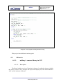
;Straight forward at 100% speed for 10 seconds (100ms x 100)
movlw
.100
movwf
MOT_VEL
movlw
.100
movwf
MOT_T_DIST_ANG
bsf
MOT_CON,FWDBACK
bsf
MOT_CON,COMTYPE
call
MOT_STR
;Nothing is done until the command has ended
CHECK_COMMANDO_END
btfss
MOT_END
goto
CHECK_COMMANDO_END
www.moway-robot.com
MOWAY
Title: mOway User Manual
Rev: v2.1.0 – June 2010
Page 55 of 137
MOT_CHECK_END function also can be used.
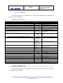
MOT_STR
Input
MOT_VEL
MOT_CON, FWDBACK
MOT_CON, COMTYPE
MOT_T_DIST
Desired speed
Movement direction
Type of command
Time value
Distance value
0
1-FWD
1-TIME
0
0
100
0-BACK
0-DIST
255
255
Output variables
FLAGS MOT_STATUS: COMOK and DWRONG
Command to move in a straight line. You will have to specify speed, direction,
type of command and the time or the distance to travel. The time has a resolution of 100
ms and the distance of 1mm and with a value of 0 returned by MOT_T_DIST the
command shall be maintained until another order is specified.
Example:
;Straight ahead at 100% speed during 10 seconds (100ms x 100)
movlw
.100
movwf
MOT_VEL
movlw
.100
movwf
MOT_T_DIST_ANG
bsf
MOT_WITH,FWDBACK
bsf
MOT_WITH,COMTYPE
call
MOT_STR
;Straight backwards at 15% speed 100mm (1mm x 100)
movlw
.15
movwf
MOT_VEL
movlw
.100
movwf
MOT_T_DIST_ANG
bcf
MOT_CON,FWDBACK
bcf
MOT_CON,COMTYPE
call
MOT_STR
MOT_CHA_VEL
Input
MOT_VEL
MOT_CON, FWDBACK
MOT_CON, RL
MOT_CON, COMTYPE
MOT_T_DIST
Desired speed
Movement direction
Left or right
Type of command
Time value
Distance value
www.moway-robot.com
0
1-FWD
1-RIGHT
1-TIME
0
0
100
0-BACK
0-LEFT
0-DIST
255
255
MOWAY
Title: mOway User Manual
Rev: v2.1.0 – June 2010
Page 56 of 137
Output variables
FLAGS MOT_STATUS: COMOK and DWRONG
A command to change the speed of any of the two motors. You will have to
specify speed, direction, motor, type of command and the time or distance to cover. The
time has a resolution of 100 ms and the distance 1 mm, and with a value of 0 returned
by MOT_T_DIST the command shall be maintained until another order is specified.
Example:
;Change speed (80% forward) of the right motor for 10 seconds
;(100ms x 100)
movlw
.80
movwf
MOT_VEL
movlw
.100
movwf
MOT_T_DIST_ANG
bsf
MOT_CON,FWDBACK
bsf
MOT_CON,COMTYPE
bsf
MOT_CON,RL
call
MOT_CHA_VEL
;Change speed (20% backwards) of the left motor and cover a distance of 100 mm
;(1mm x 100)
movlw
.20
movwf
MOT_VEL
movlw
.100
movwf
MOT_T_DIST_ANG
bcf
MOT_CON,FWDBACK
bcf
MOT_CON,COMTYPE
bcf
MOT_CON,RL
call
MOT_CHA_VEL
MOT_ROT
Input
MOT_VEL
MOT_CON, FWDBACK
MOT_CENWHEEL
MOT_CON, RL
MOT_CON, COMTYPE
MOT_T_ANG
Desired speed
Movement direction
On the center or on the wheel
Right or left
Type of command
Time value
Angle value
Output variables
FLAGS MOT_STATUS: COMOK and DWRONG
www.moway-robot.com
0
1-FWD
0x01-CE
1-RIGHT
1-TIME
0
0
100
0-BACK
0x00-WH
0-LEFT
0-ANG
255
100
MOWAY
Title: mOway User Manual
Rev: v2.1.0 – June 2010
Page 57 of 137
Command to make the mOway rotate. It is necessary to specify speed, direction,
type of rotation, the motor, type of command and the time or the rotation angle. The
time has a resolution of 100ms and with a value of 0 returned by MOT_T_ANG the
command shall be maintained until another order is specified.
Regarding the angle, the following equations show how to calculate the value of
MOT_T_ANG taking into account the desired rotation angle. If the rotation is produced
on one of the wheels more resolution is obtained. On the other hand, mechanical inertia
has to be considered, therefore it is advisable to reduce the speed to achieve greater
precision.
Equation 1. MOT_T_ANG when rotating on its center
Angleº×3.33
MOT _ T _ ANG = round
12º
Example:
;Rotate in relation to the center, to the right, at 80% speed for 10 seconds
;(100ms x 100)
movlw
.80
movwf
MOT_VEL
movlw
.100
movwf
MOT_T_DIST_ANG
movlw
0x01
movwf
MOT_CENWHEEL
bsf
MOT_CON,FWDBACK
bsf
MOT_CON,COMTYPE
bsf
MOT_CON,RL
call
MOT_ROT
;Rotate on the left wheel forward at 20% speed 180º
movlw
.20
movwf
MOT_VEL
movlw
.50
movwf
MOT_T_DIST_ANG
movlw
0x00
movwf
MOT_CENWHEEL
bsf
MOT_CON,FWDBACK
bcf
MOT_CON,COMTYPE
bcf
MOT_CON,RL
call
MOT_ROT
www.moway-robot.com
MOWAY
Title: mOway User Manual
Rev: v2.1.0 – June 2010
Page 58 of 137
MOT_CUR
Input
MOT_VEL
MOT_CON, FWDBACK
MOT_RAD
MOT_CON, RL
MOT_CON, COMTYPE
MOT_T_DIST
Desired speed
Movement direction
Radius
Right or left
Type of command
Time value
Distance value
0
1-FWD
0
1-RIGHT
1-TIME
0
0
100
0-BACK
100
0-LEFT
0-DIST
255
255
Output variables
FLAGS MOT_STATUS: COMOK and DWRONG
Command to describe a curve. It is necessary to specify speed, direction, radius,
course, type of command and the time or the distance to cover. The radius is the speed
which shall be subtracted or added to the robot’s global speed. This means that if the
specified speed is 50 and the radius 10, one of the motors shall work at 60% speed and
the other one 40%. Therefore the radius has to adhere to the following restrictions:
Equation 2. Condition 1 MOT_RAD
0 ≤ MOT _ VEL − MOT _ RAD ≤ 100
Equation 3. Condition 2 MOT_RAD
0 ≤ MOT _ VEL + MOT _ RAD ≤ 100
The time has a resolution of 100ms and the distance 1.7mm, and with a value of 0
returned by MOT_T_ANG the command shall be maintained until another order is
specified.
The speedometer counts the distance traveled by the motor located on the
external side of the curve.
Example:
;Curve forward to the right at 50% with a radius of 10 during 10 seconds
;(100ms x 100)
;VEL_I=60
;VEL_D=40
movlw
.50
movwf
MOT_VEL
movlw
.100
movwf
MOT_T_DIST_ANG
movlw
.10
movwf
MOT_RAD
bsf
MOT_CON,FWDBACK
bsf
MOT_CON,COMTYPE
bsf
MOT_CON,RL
call
MOT_CUR
www.moway-robot.com
MOWAY
Title: mOway User Manual
Rev: v2.1.0 – June 2010
Page 59 of 137
;Curve forward to the left at 80% with a radius 15 during 100mm
;(1mm x 100)
;VEL_I=95
;VEL_D=65
movlw
.80
movwf
MOT_VEL
movlw
.100
movwf
MOT_T_DIST_ANG
movlw
.15
movwf
MOT_RAD
bcf
MOT_CON,FWDBACK
bcf
MOT_CON,COMTYPE
bcf
MOT_CON,RL
call
MOT_CUR
MOT_CHECK_END
Function that waits until the movement command finishes.
Example:
;Wait the end of the command
call
MOT_CHECK_END
MOT_STOP
Output variables
FLAGS MOT_STATUS: COMOK
A command to stop the robot.
Example:
;Stop the mOway
call
MOT_STOP
MOT_RST
Input
MOT_RST_COM
The parameter that needs to be reset
Output variables
FLAGS MOT_STATUS: COMOK
www.moway-robot.com
RST_T
RST_DIST
RST_KM
Title: mOway User Manual
Rev: v2.1.0 – June 2010
Page 60 of 137
MOWAY
Resets the motor’s internal time, distance and speedometer temporary variables.
Example:
;Reset elapsed time
movlw
RST_T
movwf
MOT_RST_COM
call
MOT_RST
;Reset distance traveled
movlw
RST_D
movwf
MOT_RST_COM
call
MOT_RST
MOT_FDBCK
Input
STATUS_COM
The parameter we want to look up
STATUS_T
STATUS_A
STATUS_V_R
STATUS_V_L
STATUS_D_R
STATUS_D_L
STATUS_KM
Output variables
MOT_STATUS_DATA_0
First response byte (time, angle, speed, distance and first
speedometer byte)
MOT_STATUS_DATA_1
Second response byte (second speedometer byte)
FLAGS MOT_STATUS: COMOK and DWRONG
Command to recall different drive system parameters. We can look up elapsed
time, angle (only through the MOT_ROT command), speed of each motor, distance
traveled by each motor and the speedometer.
This function updates two variables where the required information will be saved.
All the petitions except STATUS_KM return one byte (MOT_STATUS_DATA_0)
maintaining MOT_STATUS_DATA_1 at a 0xFF value. These two variables are
updated every time a new command is sent (e.g. recall the time elapsed since the last
command). Whenever using STATUS_KM the two bytes must be considered. This
command is very useful to calculate the length of a line while the robot is following it.
Table 34. Parameter resolution
Parameter
STATUS_T
STATUS_A
Resolution
100ms/bit
3.6º/bit
www.moway-robot.com
Title: mOway User Manual
Rev: v2.1.0 – June 2010
Page 61 of 137
MOWAY
STATUS_V_R
STATUS_V_L
STATUS_D_R
STATUS_D_L
STATUS_KM
1%/bit
1%/bit
1mm/bit
1mm/bit
1mm/bit
Example:
;Recall time elapsed since the last command
movlw
STATUS_T
movwf
MOT_STATUS_COM
call
MOT_FDBCK
;E.g. Output:
;MOT_STATUS_DATA_0=0x7F => 12.7 seconds elapsed since the
;last command
;MOT_STATUS_DATA_1=0xFF; => Invalid data
byte 1
byte 0
0x01
0x08
;Recall distance traveled by the right motor since the
0000 0001 0000 0100
last command
264
Distance: 264*1mm
264mm
5.3.3.
5.3.3.1.
BZI-RF2GH4 library in assembly language
Description
With this library it is possible to communicate easily between mOway and the
BZI-RF2GH4 module.
In turn it is important to take into account that in order to call any library function,
three free stack levels are necessary and the “watchdog” must be deactivated.
In view of the fact that all the functions use the SPI protocol, it is necessary to
enable the microcontroller hardware for this purpose. To do this, just add a few lines of
code in the initial configuration of programme.
5.3.3.2.
Variables
www.moway-robot.com
MOWAY
Title: mOway User Manual
Rev: v2.1.0 – June 2010
Page 62 of 137
RF_STATUS
This read-only variable reports on the communications situation via the radio
module.
Bit7
Unused
Bit6
CONFI
GOK
Bit5
OFFOK
Bit4
ONOK
Bit3
Bit2
Bit1
RCVNW RCVOK ACK
Bit0
SNDOK
Bit 7: Unused
Bit 6: CONFIGOK: Shows whether the module has been configured correctly.
1 = The module has been configured correctly.
0 = Module has been de-configured. Communications with the module
impossible due to the absence of or incorrect electrical connection.
Bit 5: OFFOK: Shows whether the module has been switched off correctly.
1 = The module has been switched off correctly.
0 = The module has not been switched off correctly. Communications
with the module impossible due to the absence of, or incorrect electrical
connection.
Bit 4: ONOK: Shows whether the module has been switched on correctly.
1 = The module has been switched on correctly.
0 = The module is not active. Communications with the module
impossible due to the absence of, or incorrect electrical connection.
Bit 3: RCVNW: Shows whether there is still data to be read.
1 = There are data frames to be read in the radio module stack.
0 = After the last reading, the module data stack was empty. There are no
pending messages.
Bit 2: RCVOK: Reports that data has been received correctly and is accessible
for processing.
1 = Correct reception.
0 = No data has been received or the information received is corrupt.
Bit 1: ACK: Shows whether the ACK (confirmation) has been received from
the receiver following a transmission.
1 = The receiver has confirmed that the data has been received correctly.
0 = Confirmation from the receiver has not been received. This may be
due to the fact that the signal has not been received or that the stack is
full and cannot store more messages.
Bit 0: SNDOK: This shows whether data was sent the last time.
www.moway-robot.com
MOWAY
Title: mOway User Manual
Rev: v2.1.0 – June 2010
Page 63 of 137
1 = Radio module has sent the data. This bit does not indicate that
someone has heard it.
0 = It has not been possible to send the data. This may be due to a failure
in the communication with the radio module.
RF_DATA_OUT_0, RF_DATA_OUT _1,… RF_DATA_OUT _7
This group of variables consists of 8 bytes. In each transmission the contents of
the 8 bytes is sent.
RF_DATA_IN_0, RF_DATA_IN _1,… RF_DATA_IN _7
This group of variables consists of 8 bytes. In each reception these 8 bytes are
updated.
RF_DIR_OUT
This variable is of one byte only. This indicates the direction of the device that
wants to send the data.
RF_DIR_IN
This variable is of one byte only. It indicates the address of the data received.
RF_DIR
This variable is of one byte only. It indicates the address with which the module is
configured.
5.3.3.3.
Functions
The library consists of nine functions that will make the task of developing a
communications application with BZI-RF2GH4 modules considerably easier. A brief
description of each one of these functions is given below.
Table 35. Assembler RF functions.
RF_CONFIG
RF_CONFIG_SPI
RF_ON
RF_OFF
Functions for the BZI-RF2GH4 module
Configures the inputs and outputs of the microcontroller as
well as the radio module parameters.
Configures the inputs and outputs of the microcontroller as
well as the parameters required to use the SPI bus.
Activates the radio frequency module in receive mode.
Deactivates the radio frequency module and leaves it in low
www.moway-robot.com
Title: mOway User Manual
Rev: v2.1.0 – June 2010
Page 64 of 137
MOWAY
consumption mode.
Sends a data frame (8 Bytes) to the address indicated.
RF_SEND
Checks whether a reception has occurred and if so, collects the
RF_RECEIVE
frame.
Carries out the same function as RF_RECEIVE but in this case
RF_RECEIVE_INT
checks whether there has been an interruption.
This routine enables the external interruption for the radio
RF_INT_EN
module in the microcontroller.
RF_CONFIG_SPI
The speed of the SPI must not exceed 8 Mhz and therefore the use of this function
is limited to PIC microcontrollers with a frequency of less than 32Mhz. The different
parameters of the SPI module and the pins of the PIC are configured in the function.
Table 36. SPI configuration
PIN RF
SCK
SDI
SDO
PIN PIC
RC3
RC5
RC4
RF_CONFIG
Input variables
RF_DIR
RF_CHN
Device address. Must be a value of between 0x01 and 0xFE.
Channel to be used in the communication. Must be a value of
between 0x00 and 0x7F (128 channels).
Output variables
FLAGS: CONFIGOK
This function configures the transceptor, enabling its own watch address and the
‘broadcast’ address. In trun, it configures other parameters such as the PIC pins, the
channel, the transmission speed, the emitting power, the address length, the CRC code
length, etc.
Table 37. RF pin configuration
PIN RF
IRQ
CSN
CE
PIN PIC
RB0
RF2
RH4
The channel must be common to all the modules that are going to take part in the
communication.
Users can choose any channel from among the 128 available.
Nevertheless, if there is more than one communication in the environment between
modules in different channels, a spacing of 2 must be left between the channels to be
used in order to avoid interferences, thus leaving 32 channels usable. Another question
www.moway-robot.com
MOWAY
Title: mOway User Manual
Rev: v2.1.0 – June 2010
Page 65 of 137
to be taken into account is the existence of other technologies that use the ISM 2.4GHz
band (Wi-Fi, Bluetooth, etc.) and that might also cause interference in one of the
channels.
Image 43. RF channels
The address assigned to each device must be one-way within each channel.
If the SPI communication of the PIC is configured incorrectly, the connection has
been made incorrectly or in the absence of the module; the CONFIGOK RF_STATUS
bit of will remain at 0.
RF_ON
Output variables
FLAGS: ONOK
This routine activates the radio module in watch mode in order to be able to
receive data and/or send data.
It is important to take into consideration that, following the call to this routine, the
module requires 2.5 ms to be ready.
If the SPI communication of the PIC is configured incorrectly, the connection has
been made incorrectly or in the absence of the module; the ONOK RF_STATUS bit
will remain at 0.
Example:
;--[Configuration without interruption and activation routine]----;Configure SPI modules of the PIC
call
RF_CONFIG_SPI
; Configure RF module (own channel and address)
movlw
0x01
; Own address
movwf
RF_DIR
movlw
movwf
0x40
RF_CHN
;Channel
call
btfss
RF_CONFIG
RF_STATUS,CONFIGOK
www.moway-robot.com
MOWAY
nop
Title: mOway User Manual
Rev: v2.1.0 – June 2010
Page 66 of 137
;Module not configured
; Activate RF module
call
RF_ON
btfss
RF_STATUS,ONOK
nop
;Module not initialised
;-----------------------------------------------------------------------------
RF_OFF
Output variables
FLAGS: OFFOK
This routine deactivates the radio module leaving this in low consumption mode.
It does not clear the established configuration.
If the SPI communication of the PIC is configured incorrectly, the connection has
been made incorrectly or in the absence of the module; the OFFOK RF_STATUS bit
will remain at 0.
RF_SEND
Input variables
RF_DIR_OUT
RF_DATA_OUT_0 –
RF_DATA_OUT_7
Direction to which it is required to send the data (1 byte).
Variables to be transmitted (8 bytes).
Output variables
FLAGS: SNDOK and ACK
This function sends 8 bytes of data to the indicated address and reports the correct
reception to the recipient. Following this, the device will return to watch mode.
If a message is sent to the address 0x00, this will be received by all the modules
on the same channel. It must be taken into account that the module accepts the first
ACK it receives, therefore we cannot be certain that the data has arrived at all the
devices.
Example:
;---------------------[Data sending routine]-----------------------; Preparation of the receiver address
; and of the data.
movlw
0x02
;Receiver address
www.moway-robot.com
MOWAY
movwf
RF_DIR_OUT
clrf
clrf
clrf
clrf
clrf
clrf
clrf
clrf
RF_DATA_OUT_0
RF_DATA_OUT_1
RF_DATA_OUT_2
RF_DATA_OUT_3
RF_DATA_OUT_4
RF_DATA_OUT_5
RF_DATA_OUT_6
RF_DATA_OUT_7
call
btfss
nop
btfss
nop
RF_SEND
;Send frame
RF_STATUS,SNDOK
;Not sent
RF_STATUS,ACK
;No ACK
Title: mOway User Manual
Rev: v2.1.0 – June 2010
Page 67 of 137
;Data to be sent
;-----------------------------------------------------------------------------
RF_RECEIVE
Output variables
RF_DIR_IN
RF_DATA_IN_0 –
RF_DATA_IN_7
RCVOK and RCVNW
Address of the person who has sent the frame
Frame received from the address indicated.
This routine is responsible for checking whether a reception has taken place and if
so, it returns the data received. Likewise, it reports whether there is any data that has not
been read in the reception FIFO of the module.
When a frame is received, the RCVNW bit of the RF_STATUS variable must be
checked and if this is active, the RF_RECEIVE function must be called up once again
after processing the data. The transceptor has a 3-level stack, and therefore if the receive
function is not called before the stack is filled, the device will be unable to receive more
data.
As interruptions are not used, the probability of losing packages, with high traffic
levels, is moderate. It is advisable to use this only in environments in which there are
just a few devices and/or little data traffic. This problem can also resolved by causing
the images to resend the same frame until the communication is correct, but in
environments with a great deal of traffic, collisions increase exponentially, causing
considerable increases in sending times.
Example:
;-----[ Reception routine without interruption]---------------www.moway-robot.com
MOWAY
Title: mOway User Manual
Rev: v2.1.0 – June 2010
Page 68 of 137
RECEIVE_DATA
call
RF_RECEIVE
btfsc
RF_STATUS,RCVOK
nop
;Procces data
btfsc
RF_STATUS,RCVNW
goto
RECEIVE_DATA
;-----------------------------------------------------------------------------
RF_RECEIVE_INT
Output variables
RF_DIR_IN
RF_DATA_IN_0 –
RF_DATA_IN_7
RCVOK, RCVNW
Address of the person who has sent the frame
Frame received from the address indicated.
This is the optimum reception routine. This routine is virtually the same as
RF_RECEIVE, the difference being that this one operates by interruption. For this
reason, it must be placed within the interaction code and the interruptions must be
configured beforehand (RF_INTER_EN). It is responsible for checking that an external
interruption has occurred (RB0) and if so, it clears the interruption flag. The probability
of losing packages is minimal. Even so, it is advisable for transmitters to resend if the
send flag is not activated.
Example:
;--------- -[Data reception routine with interruption]--------READ_MORE_DATA
call
RF_RECEIVE_INT
btfsc
RF_STATUS,RCVOK
nop
; Process data
btfsc
RF_STATUS,RCVNW
goto
READ_MORE_DATA
goto
INTERRUPTION_OUT
;----------------------------------------------------------------------------RF_INT_EN
This routine is responsible for enabling the external interruption of the
microcontroller (RB0) that uses the RF module in data reception. For this reason, the
RB0 pin is configured as input. Although the module can be managed without
interruptions, the minimum response time is not guaranteed.
www.moway-robot.com
MOWAY
Title: mOway User Manual
Rev: v2.1.0 – June 2010
Page 69 of 137
Example:
;--[Configuration with interruption and activation routine]----; Enable interruptions
call
RF_INT_EN
;Configure SPI modules of the PIC
call
RF_CONFIG_SPI
; Configure RF module (own channel and address)
movlw
0x01
; Own address
movwf
RF_DIR
movlw
movwf
0x40
RF_CHN
;Channel
call
btfss
nop
RF_CONFIG
RF_STATUS,CONFIGOK
;Module not configured
; Activate RF module
call
RF_ON
btfss
RF_STATUS,ONOK
nop
;Module not initialized
;------------------------------------------------------------------------5.3.3.4.
Flow diagram for sending and receiving data
www.moway-robot.com
Title: mOway User Manual
Rev: v2.1.0 – June 2010
Page 70 of 137
MOWAY
Interrupción ext
Define
RF_DIR
IRQ=1
RF_RECEIVE
RF_RECEIVE
_INT
Define
RF_DATA
IRQ=0
RCVOK
RCVOK
RF_SEND
1
SNDOK
0
No sent
0
ACK no recived
1
1
process data
0
1
process data
0
1
RCVNW
ACK
1
0
RCVNW
0
Data sent and
ACK received
Out interruption
Out receive
service
Diagram 1. Sent data in
assembler
Diagram 2. Receive interruption
in assembler
Diagram 3. Reception in
assembler
www.moway-robot.com
MOWAY
Title: mOway User Manual
Rev: v2.1.0 – June 2010
Page 71 of 137
6. Programming Moway with C18 Compiler
C18 is a compiler that can be acquired in the market and which supports the
PIC18F86J50 microcontroller. In the Moway Website the libraries required to manage
sensors, motors and RF modules, written for the compiler.
Its greatest advantage is that it compiles in C language. Managing numerical
variables (char, int, etc.) and flow controlling structures (if, for, etc.) is very simple and
it includes many pre-compiled functions which greatly assist programming (I2C, SPI).
However, the size of the generated programs is larger than with assembly language.
To summarize:
• Very interesting if you wish to start working with Moway quickly.
• Very interesting to carry out easy or average difficulty tasks.
• Inadequate for programs with large coding.
• Inadequate for critical response timeframes
6.1.
Creating a project
Use the MPLAB IDE Project Wizard to create the first project quickly. C18
compiler has to be installed. These example is made by MPlab v8.3.
Image 44. Project Wizard
www.moway-robot.com
MOWAY
1. First select the PIC installed in mOway: PIC18F86J50.
Image 45. PIC selection
2. Choose C18 C compiler.
Image 46. Tool selection
www.moway-robot.com
Title: mOway User Manual
Rev: v2.1.0 – June 2010
Page 72 of 137
MOWAY
Title: mOway User Manual
Rev: v2.1.0 – June 2010
Page 73 of 137
3. In the next step user has to specify location.
Image 47. Location
4. Add mOway libraries. It is highly recommended to copy those libraries to the folder.
Image 48. Add libraries
www.moway-robot.com
MOWAY
Title: mOway User Manual
Rev: v2.1.0 – June 2010
Page 74 of 137
8. With the steps above the project will now be created, the next step is to create a .C
file for the source code.
Image 49. Wizard ends
9. The next step is to open the project and create a new file (New File) saving it in the
same folder of the project as Main.c. This will be our source file.
Image 50. .C creation
www.moway-robot.com
MOWAY
Title: mOway User Manual
Rev: v2.1.0 – June 2010
Page 75 of 137
10. Finally, the source file is added to the project accessing Project/Add Files to
Project… After that user has to add Linker Script to the project. This can find y
mOwayPack o in another example project.
Image 51. Project with .C
6.2.
First program in C18
To generate the first program a project has to be created first (previous chapter).
This first basic program will enable the mOway to avoid obstacles.
1. Add code to redefinition of the reset and interrupt codes. This code is required.
Also lib_sen_moway.h is added.
www.moway-robot.com
MOWAY
Title: mOway User Manual
Rev: v2.1.0 – June 2010
Page 76 of 137
Image 52. First program: vector redefinition.
2. Next, the SEN_CONFIG function is called to configure the microcontroller’s
inputs and outputs.
3. Add winking to one of the LEDs.
4. Test the program on mOway programming it in mOwayGUI and verify that the
green LED blinks.
www.moway-robot.com
MOWAY
Title: mOway User Manual
Rev: v2.1.0 – June 2010
Page 77 of 137
Image 53. First program: configuration and LED
5. To detect obstacles call up the SEN_OBS_DIG() with OBS_CENTER_L as
input value.
6. If it detects an obstacle the front LEDs light up.
7. Test the program on mOway and verify that the LEDs switch on when an object
is placed close to the front part of the mOway.
www.moway-robot.com
MOWAY
Title: mOway User Manual
Rev: v2.1.0 – June 2010
Page 78 of 137
Image 54. First program: detecting obstacles
8. We then add movement to the robot: unrestricted straight command until it
encounters an obstacle.
9. lib_mot_asm.inc is added to the project.
10. MOT_CONFIG is called to be able to use Diver system.
11. Go straight on the first time.
12. When it encounters an obstacle a command is sent to rotate 180º and the top red
LED lights up (the front LEDs will not operate). The robot will wait until this
command has ended and will then continue moving straight forward.
www.moway-robot.com
MOWAY
Title: mOway User Manual
Rev: v2.1.0 – June 2010
Page 79 of 137
Image 55. First program: detecting obstacles moving
This project is included in the mOway pack.
6.3.
Libraries
6.3.1.
6.3.1.1.
mOway´s sensors library in C18
Description
The library includes a series of functions in charge of reading the data provided by
the robot’s sensors. They configure the input and output ports, the microcontroller’s
ADC and the luminous indicators.
www.moway-robot.com
Title: mOway User Manual
Rev: v2.1.0 – June 2010
Page 80 of 137
MOWAY
6.3.1.2.
Functions
A series of functions to control mOway’s sensors and LED diodes are included in
the lib_sen_moway library.
Table 38. C function summary
Name
Input
constants
void SEN_CONFIGURAR(void)
unsigned char SEN_LIGHT(void)
unsigned char SEN_BATTERY(void)
unsigned char SEN_TEMPERATURE (void)
unsigned char SEN_MIC_ANALOG (void)
unsigned char SEN_MIC_DIG (void)
unsigned
char
SEN_SPEAKER(unsigned
unsigned char, unsigned char)
char,
unsigned char SEN_ACCE_XYZ_READ(unsigned char)
unsigned char SEN_ACCE_CHECK_TAP(void)
unsigned char SEN_OBS_DIG(unsigned char)
unsigned char SEN_OBS_ANALOG(unsigned char)
unsigned char SEN_LINE_DIG(unsigned char)
unsigned char SEN_LINE_ANALOG (unsigned char)
void LED_FRONT_ON(void)
void LED_BRAKE_ON(void)
void LED_TOP_RED_ON(void)
void LED_TOP_GREEN_ON(void)
void LED_FRONT _OFF(void)
void LED_BRAKE_OFF(void)
void LED_TOP_RED_OFF(void)
void LED_TOP_GREEN_OFF(void)
void LED_FRONT _ON_OFF(void)
void LED_BRAKE_ON_OFF(void)
void LED_TOP_RED_ON_OFF(void)
void LED_TOP_GREEN_ON_OFF(void)
Description
-
Configured to use the sensors.
-
Reads light sensor values.
-
Returns the battery level.
-
Detects the temperature in ºC.
-
Detects sound intensity.
-
Detects if there is sound or not.
SPEAKER_OFF
SPEAKER_ON
SPEAKER_TIME
ACCE_CHECK_X
ACCE_CHECK_Y
ACCE_CHECK_Z
-
Emits tones in a frequency between 250
Hz and 65 KHz.
Calculates the X,Y,Z axes acceleration of
mOway.
Detects if mOway has been taped.
OBS_SIDE_L
OBS_CENTER_L
OBS_CENTER_R
OBS_SIDE_R
OBS_SIDE_L
OBS_CENTER_L
OBS_CENTER_R
OBS_SIDE_R
LINE_R
LINE_L
LINE_R
LINE_L
-
Detects obstacles
Front LED on
-
Brake LED on
-
Top red LED on
-
Top green LED on
-
Front LED off
-
Brake LED off
-
Top red LED off
-
Top green LED off
-
Front LED blink
-
Brake LED blink
-
Top red LED blink
-
Top green LED blink
Detects the distance to obstacles
Detects dark zones (black lines)
Detects surface colors
void SEN_CONFIG(void)
This function configures the inputs and outputs required to manage the sensors
and initialize the variables.
www.moway-robot.com
MOWAY
Title: mOway User Manual
Rev: v2.1.0 – June 2010
Page 81 of 137
Table 39. PIC-sensor connections
Pin PIC
PORTA
RA0
RA1
RA2
RA3
RA5
PORTB
RB1
RB2
RB3
RB5
RB6
PORTC
RC7
PORTD
RD1
RD4
RD5
RD6
RD7
PORTE
RE5
PORTF
RF5
RF6
PORTH
RH5
RH6
RH7
PORTJ
RJ6
RJ7
I/O
Sensor
I
I
I
I
I
Light
Central left infrared receiver
Right line sensor receiver
Side left infrared receiver
Left line sensor receiver
I
I
O
O
O
First interruption of the accelerometer
Second interruption of the accelerometer
Speaker
Top red LED
Top green LED
O
Front LED
O
I
O
O
I
Line sensors transmitter
SDO signal for the SPI communication (accelerometer)
SDI sinal for the SPI communication(accelerometer)
Clock sinal for the SPI communication(accelerometer)
Chip Select for the SPI communication(accelerometer)
O
Brake LED
I
I
Side right infrared receiver
Central right infrared receiver
I
I
I
Tempreature sensor
Battery measurer
Microphone
O
I/O
Infrared transmitter
Free pad
unsigned char SEN_LIGHT(void)
Output
Percentage of ambient light.
The SEN_LIGHT function captures the analog value generated by the inciding
light on the photo-transistor. To achieve this follow these steps:
•
•
•
•
•
Activate the ADC.
Wait for the data acquisition process to end (100us).
Read the analog value.
Calculate the inciding light percentage based on the analog voltage
measurement.
Returns the percentage of ambient light.
www.moway-robot.com
MOWAY
Title: mOway User Manual
Rev: v2.1.0 – June 2010
Page 82 of 137
unsigned char SEN_BATTERY(void)
Output
Percentage of battery level.
The SEN_BATTERY function captures the analog value of the battery
achieve this, function follows these steps:
•
•
•
•
•
16
. To
Activate the ADC.
Wait for the data acquisition process to end (100us).
Read the analog value.
Calculate the battery level percentage based on the analog voltage measurement.
Returns battery level.
unsigned char SEN_TEMPERATURE(void)
Output
Temperature in ºC.
The SEN_TEMPERATURE function captures the analog value that depends on
the temperature captured by the thermistor17. To achieve this, function follows these
steps:
•
•
•
•
•
Activate the ADC.
Wait for the data acquisition process to end (100us).
Read the analog value.
Calculate the temperature based on the analog voltage measurement.
Returns temperature in %.
unsigned char SEN_MIC_ANALOG(void)
Output
Sound intensity.
The SEN_MIC_ANALOG function captures the analog value that depends on the
sound intensity from the microphone. To achieve this, function follows these steps:
•
•
•
•
Activate the ADC.
Wait for the data acquisition process to end (100us).
Read the analog value.
Returns amplified microphone value.
16
17
The output value can differ from mOwayGUI
Sensor measures mOway´s temperature which can be different from ambient temperature.
www.moway-robot.com
Title: mOway User Manual
Rev: v2.1.0 – June 2010
Page 83 of 137
MOWAY
unsigned char SEN_MIC_DIG(void)
Output
Indicates if a sound has been detected
The SEN_MIC_DIG function indicates if there is sound or not. To achieve this
function follows these steps:
•
Returns the digital value of microphone input.
void
SEN_SPEAKER(unsigned char SEN_SPEAKER_FREQ,
SEN_SPEAKER_TIME, unsigned char SEN_SPEAKER_ON_OFF)
unsigned
char
Input variables
SEN_SPEAKER_FREQ
SEN_SPEAKER_TIME
SEN_SPEAKER_ON_OFF
Sound frequency (see table).
Time.
On, off or time.
The SEN_SPEAKER function emits tones in a frequency between 250 Hz and 65
KHz. SEN_SPEAKER_ON_OFF is going to say if we want to switch on, switch off or
activate the speaker an amount of time (100ms intervals). To achieve this, function
follows these steps:
•
•
PWM on with frequency SEN_SPEAKER_FREQ and 50% of duty.
If SEN_SPEAKER_ON_OFF is SPEAKER_TIME(2) function waits until
command finishes.
Table 40. Allowed values for SEN_SPEAKER_ON_OFF
Define
SPEAKER_OFF
SPEAKER_ON
SPEAKER_TIME
Valor
0
1
2
Table 41. SEN_SPEAKER_FREQ vs PWM frequency
SEN_SPEAKER_FREQ
0
10
20
30
40
50
60
70
PWM frequency
Hz
0,0000000
5681,8181818
2976,1904762
2016,1290323
1524,3902439
1225,4901961
1024,5901639
880,2816901
www.moway-robot.com
Title: mOway User Manual
Rev: v2.1.0 – June 2010
Page 84 of 137
MOWAY
80
90
100
110
120
130
140
150
160
170
180
190
200
210
220
230
240
250,
255
771,6049383
686,8131868
618,8118812
563,0630631
516,5289256
477,0992366
443,2624113
413,9072848
388,1987578
365,4970760
345,3038674
327,2251309
310,9452736
296,2085308
282,8054299
270,5627706
259,3360996
249,0039841
244,1406250
unsigned char SEN_OBS_DIG(unsigned char SEN_CHECK_OBS)
Input variables
SEN_CHECK_OBS
Which sensor must be read
Output
Indicates if there is obstacle or not.
This function indicates if the obstacle is situated on the right front side or on the
left front side. To achieve this function follows these steps:
•
•
•
•
•
•
•
Ensure that there is no noise source interference before sending the infrared light
pulse.
Emit the infrared light pulse to detect obstacles. This light-beam will be
reflected back if there is any existing obstacle and this signal will be perceived
by the infrared receiver.
Check for any eventual signals from the four IR receivers.
Copy the digital receiver’s value to the output variables.
Deactivate the infrared diode.
Check for interfering signals.
If there is no signal interferences and the process develops normally returns
value.
www.moway-robot.com
MOWAY
Title: mOway User Manual
Rev: v2.1.0 – June 2010
Page 85 of 137
Table 42. Allowed values for SEN_CHECK_OBS
Define
OBS_CENTER_L
OBS_SIDE_L
OBS_CENTER_R
OBS_SIDE_R
Value
0
1
2
3
unsigned char SEN_OBS_ANALOG(unsigned char SEN_CHECK_OBS)
Input variable
SEN_CHECK_OBS
Which sensor must be read
Output
Indicates if there is obstacle or not.
This function indicates if the obstacle is on the right front side or on the left front
side and its distance from the robot. To achieve this follow the steps indicated below:
•
•
•
•
•
•
•
Ensure that there is no noise source interferences before you send the infrared
light pulse.
Emit the infrared light pulse to detect obstacles.
Activate the ADC.
Check for any possible signals from the four IR receivers.
Copy the analog receiver’s value to the output variables. The higher the value
the shorter the distance will be.
Deactivate the infrared diode.
Check for interfering signals. If there is no signal interferences and the process
develops normally value is returned.
Table 43. SEN_CHECK_OBS allowed values
Define
OBS_CENTER_L
OBS_SIDE_L
OBS_CENTER_R
OBS_SIDE_R
Value
0
1
2
3
unsigned char SEN_ACCE_XYZ_READ(unsigned char SEN_CHECK_ACCE)
Input variable
SEN_CHECK_ACCE
Which axis must be read
Output
Acceleration value
SEN_ACCE_XYZ_READ returns the acceleration of the robot in the 3 axes.
Resolution is ±0.0156G/bit. Value 0 is -2G and 255 is 2G.
www.moway-robot.com
MOWAY
Title: mOway User Manual
Rev: v2.1.0 – June 2010
Page 86 of 137
Image 56. mOway axes
•
•
•
•
•
Communication between microcontroller and accelerometer is SPI.
Command is sent to change the mode of the accelerometer to “measure”.
Function waits until the value is calculated.
Value is read.
Change the mode to “tap detection”.
Table 44. SEN_CHECK_ACCE allowed values.
Define
ACCE_CHECK_X
ACCE_CHECK_Y
ACCE_CHECK_Z
Value
0
1
2
unsigned char SEN_ACCE_CHECK_TAP(void)
Output
1: Tap
2: Tap tap
Accelerometer detects taps.
•
•
•
Communication between microcontroller and accelerometer is SPI
Checks if “tap interrupt” has been detected
SEN_ACCE_TAP value is changed.
unsigned char SEN_LINE_DIG(unsigned char SEN_CHECK_LINE)
Input variable
SEN_CHECK_LINE
Which sensor must be read
Output
Digital value of the sensor
The SEN_LINE_DIG function indicates whether the sensors are or are not on a
dark surface. To achieve this function follows the steps indicated below:
www.moway-robot.com
MOWAY
•
Title: mOway User Manual
Rev: v2.1.0 – June 2010
Page 87 of 137
Emit the infrared light pulse to detect the line. This light-beam will be reflected
back if the line is detected and this signal will be perceived by the infrared
receiver.
Wait for the data acquisition process to end (900 us).
Read the sensor.
Copy the value to the SEN_LINE variable. If the surface is dark (no light is
reflected) the variable will return a‘1’ value.
•
•
•
Table 45. SEN_CHECK_LINE allowed values
Define
LINE_L
LINE_R
Value
0
1
unsigned char SEN_LINE_ANALOG(unsigned char SEN_CHECK_LINE)
Input variables
SEN_CHECK_LINE
Which sensor must be read
Output
Analog value of the sensor
The SEN_LINE_ANALOG function indicates the light reflected in the
optocouplers 18. To do this function follows the steps indicated below:
•
Emit the infrared light pulse to detect the line. This light-beam will be reflected
back if the line is detected and this signal will be perceived by the infrared
receiver.
Wait for the data acquisition process to end (900us).
Read the sensor.
Copy this value to the SEN_LINE variable. The higher the values the darker will
the surfaces be.
•
•
•
Table 46. SEN_CHECK_LINE allowed values
Define
LINE_L
LINE_R
void LED_BRAKE_ON(void)
Function to switches on the brake LED.
void LED_FRONT_ON(void)
Function to switches on the front LED.
18
Due to tolerance two different sensors can differ from each other.
www.moway-robot.com
Value
0
1
MOWAY
void LED_TOP_RED_ON(void)
Function to switches on red LED.
void LED_TOP_GREEN_ON(void)
Function to switches on green LED.
void LED_BRAKE_OFF(void)
Function to switches off the brake LED.
void LED_FRONT_OFF(void)
Function to switches off the front LED.
void LED_TOP_RED_OFF(void)
Function to switches off the red LED.
void LED_TOP_GREEN_OFF(void)
Function to switches off the green LED.
void LED_BRAKE_ON_OFF(void)
Blink the brake LED.
void LED_FRONT_ON_OFF(void)
Blink the front LED.
void LED_TOP_RED_ON_OFF(void)
Blink the red LED.
void LED_TOP_GREEN_ON_OFF(void)
Blink the green LED.
www.moway-robot.com
Title: mOway User Manual
Rev: v2.1.0 – June 2010
Page 88 of 137
MOWAY
6.3.2.
6.3.2.1.
Title: mOway User Manual
Rev: v2.1.0 – June 2010
Page 89 of 137
mOway´s motor library C18
Description
The library includes a series of functions in charge of sending I2C commands to
the Drive System, which will be responsible for controlling the motors and therefore
releasing the main microcontroller so it can carry out other tasks.
Communications with the motor module are conducted via the I2C protocol. Any
microcontroller with this kind of communications can control the motors; use the
libraries in assembly. The format for the Driving System I2C frame can be observed in
the following illustrations. Each of these frames lasts approximately 350 us.
Image 57. Command format: MOT_STR, MOT_CHA_VEL
Image 58. Command format: MOT_CUR, MOT_ROT
Image 59. Command format: MOT_STOP, MOT_RST
Image 60. Command format: MOT_FDBCK
6.3.2.2.
Functions
A series of functions designed to control mOway’s drive system are included in
the lib_mot_moway library.
www.moway-robot.com
Title: mOway User Manual
Rev: v2.1.0 – June 2010
Page 90 of 137
MOWAY
Table 47. Summary of functions in C for lib_mot_moway
Name
Input
Return
void MOT_CONFIG(void)
Description
Configuration
to
communicate
with
the
motors
A command to move in a
straight line
unsigned char MOT_STR(
unsigned char, unsigned char,
unsigned char, unsigned char)
MOT_VEL
FWDBACK
COMTYPE
MOT_T_DIST
0: Correct dispatch
1: Incorrect dispatch
2: Incorrect data
unsigned char MOT_CHA_VEL(
unsigned char, unsigned char,
unsigned char, unsigned char,
unsigned char)
MOT_VEL
FWDBACK
RL
COMTYPE
MOT_T_DIST
0: Correct dispatch
1: Incorrect dispatch
2: Incorrect data
A command to change the
speed of a motor
unsigned char MOT_ROT(
unsigned char, unsigned char,
unsigned char, unsigned char,
unsigned char, unsigned char)
MOT_VEL
FWDBACK
MOT_CENWHEEL
RL
COMTYPE
MOT_T_ANG
0: Correct dispatch
1: Incorrect dispatch
2: Incorrect data
A command to rotate the
robot
unsigned char MOT_CUR(
unsigned char, unsigned char,
unsigned char, unsigned char,
unsigned char, unsigned char)
MOT_VEL
FWDBACK
MOT_RAD
RL
COMTYPE
MOT_T_DIST
0: Correct dispatch
1: Incorrect dispatch
2: Incorrect data
A command to execute a
curve
0: Correct dispatch
1: Incorrect dispatch
0: Correct dispatch
1: Incorrect dispatch
A command to stop the robot
0: Correct dispatch
1: Incorrect dispatch
A command to determine the
motor’s status
unsigned char MOT_STOP(void)
RST_COM
unsigned char MOT_RST(
unsigned char)
unsigned char*
MOT_FDBCK(void)
A command to reset the
temporary variables for time
and distance
void MOT_CONFIG(void)
This function configures the inputs and outputs so the microcontroller can
communicate with the Drive System.
Table 48. Pic-drive system connections
Pin PIC
PORTE
RE7
RE0
RE1
I/O
Sensor
I Indicates when the motor
command.
O SCL of the I2C protocol
O SDA of the I2C protocol
ends
the
Port RE7 indicates the end of a command. This port is labeled as MOT_END in
the library.
Example:
//Straight forward at 100% speed for 10 seconds (100ms x 100)
www.moway-robot.com
MOWAY
Title: mOway User Manual
Rev: v2.1.0 – June 2010
Page 91 of 137
MOT_STR(100, FWD, TIME, 100);
//No action is taken until the command ends
while(!MOT_END){}
unsigned char MOT_STR(unsigned char MOT_VEL,unsigned
FWDBACK,unsigned char COMTYPE, unsigned char MOT_T_DIST)
char
Input
MOT_VEL
FWDBACK
COMTYPE
MOT_T_DIST
Desired speed
Movement direction
Type of command
Time value
Distance value
0
FWD
TIME
0
0
100
BACK
DISTANCE
255
255
Function Return
0: Correct dispatch
1: Incorrect dispatch
2: Incorrect data
The command has been sent correctly
The command has not been sent. Connection problem
The data is incorrect
Command to move in a straight line. It is necessary to specify speed, direction,
type of command and the time or the distance to cover. The time has a resolution of
100ms and the distance of 1 mm, and with a value of 0 returned by MOT_T_DIST the
command will be maintained until another order is given.
Example:
//Straight forward at 100% speed during 10 seconds (100 ms x 100)
MOT_STR(100, FWD, TIME, 100);
//Straight backwards at 15% speed 100mm (1mm x 100)
MOT_STR(15, BACK, DISTANCE, 100);
unsigned char MOT_CHA_VEL(unsigned char MOT_VEL,unsigned char
FWDBACK,unsigned char RL,unsigned char COMTYPE,unsigned char
MOT_T_DIST)
Input
MOT_VEL
FWDBACK
RL
COMTYPE
MOT_T_DIST
Desired speed
Movement direction
Right or left
Type of command
Time value
Distance value
0
FWD
RIGHT
TIME
0
0
100
BACK
LEFT
DISTANCE
255
255
Function Return
0: Correct dispatch
1: Incorrect dispatch
2: Incorrect data
The command has been sent correctly
The command has not been sent. Connection problem
The data is incorrect
www.moway-robot.com
MOWAY
Title: mOway User Manual
Rev: v2.1.0 – June 2010
Page 92 of 137
A command to change the speed of any of the two motors. It is necessary to
specify speed, direction, motor, type of command and the time or distance to be
traveled. The time has a resolution of 100 ms and the distance 1mm, and with a value of
0 returned by MOT_T_DIST the command shall be maintained until another order is
specified.
Example:
//Change speed (80% forward) of the right motor during 10 seconds
//(100 ms x 100)
MOT_CHA_VEL(80, FWD, RIGHT, TIME, 100) ;
//Change speed (20% backwards) of the left motor and travels a distance of 100
//mm (1 mm x 100)
MOT_CHA_VEL(20, BACK, LEFT, DISTANCE, 100) ;
unsigned char MOT_ROT(unsigned char MOT_VEL,unsigned char
FWDBACK,unsigned char MOT_CENWHEEL,unsigned char RL,unsigned char
COMTYPE,unsigned char MOT_T_ANG)
Input
MOT_VEL
FWDBACK
MOT_CENWHEEL
RL
COMTYPE
MOT_T_ANG
Desired speed
Movement direction
On center or wheel
Right or left
Type of command
Time value
Angle value
0
FWD
CENTER
RIGHT
TIME
0
0
100
BACK
WHEEL
LEFT
DISTANCE
255
100
Function Return
0: Correct dispatch
1: Incorrect dispatch
2: Incorrect data
The command has been sent correctly
The command has not been sent. Connection problem
The data is incorrect
Command to make the Moway rotate. It is necessary to specify speed, direction,
type of rotation, motor, type of command and the time or the angle to rotate. The time
has a resolution of 100 ms, and with a value of 0 returned by MOT_T_ANG the
command shall be maintained until another order is specified.
For the angle, the equations below illustrate how to calculate the value of
MOT_T_ANG taking into account the desired rotation angle. If the rotation is produced
on one of the wheels more resolution is obtained. On the other hand, mechanical inertia
must also be considered; therefore to achieve greater precision it is advisable to reduce
the speed.
www.moway-robot.com
MOWAY
Title: mOway User Manual
Rev: v2.1.0 – June 2010
Page 93 of 137
Equation 4. MOT_T_ANG when rotating on its center
Angleº×3.33
MOT _ T _ ANG = round
12º
Example:
//Rotation in relation to the center to the right at 80% speed for 10 seconds
//(100ms x 100)
MOT_ROT(80, FWD, CENTER, RIGHT, TIME, 100) ;
//Rotation in relation to the left wheel forward at 20% speed 180º
MOT_ROT(20, BACK, WHEEL, LEFT, ANGLE, 50) ;
unsigned char MOT_CUR(unsigned char MOT_VEL,unsigned
FWDBACK,unsigned char MOT_RAD,unsigned char RL,unsigned
COMTYPE, unsigned char MOT_T_DIST)
char
char
Input
MOT_VEL
FWDBACK
MOT_RAD
RL
COMTYPE
MOT_T_DIST
Desired speed
Movement direction
Radius
Right or left
Type of command
Time value
Distance value
0
FWD
0
RIGHT
TIME
0
0
100
BACK
100
LEFT
DISTANCE
255
255
Function Return
0: Correct dispatch
1: Incorrect dispatch
2: Incorrect data
The command has been sent correctly
The command has not been sent. Connection problem
The data is incorrect
Command to describe a curve. It is necessary to specify speed, direction, radius,
course, type of command and the time or the distance to be traveled. The radius is the
speed that will be subtracted or added to the robot’s global speed. This means that if the
specified speed is 50 and the radius 10, one of the motors shall work at 60% speed and
the other one 40%. Therefore the radius has to adhere to the following restrictions:
Equation 5. Condition 1 MOT_RAD
0 ≤ MOT _ VEL − MOT _ RAD ≤ 100
Equation 6. Condition 2 MOT_RAD
0 ≤ MOT _ VEL + MOT _ RAD ≤ 100
The time has a resolution of 100 ms and the distance 1 mm, and with a value of 0
returned by MOT_T_ANG the command shall be maintained until another order is
specified. The motor measures the distance traveled by the motor located on the external
side of the curve.
www.moway-robot.com
MOWAY
Title: mOway User Manual
Rev: v2.1.0 – June 2010
Page 94 of 137
Example:
//Curve to the right at 50% with a radius of 10 for 10 seconds
//(100ms x 100)
//VEL_I=60
//VEL_D=40
MOT_CUR(50, FWD, 10, RIGHT, TIME, 100) ;
//Curve to the left at 80% with a radius 15 for 100mm
//(1mm x 100)
//VEL_I=95
//VEL_D=65
MOT_CUR(80, BACK, 15, LEFT, DISTANCE, 100) ;
unsigned char MOT_STOP(void)
Function Return
0: Correct dispatch
1: Incorrect dispatch
The command has been sent correctly
The command has not been sent. Connection problem
Command to stop the robot.
Example:
// Moway stop
MOT_STOP() ;
unsigned char MOT_RST(unsigned char RST_COM)
Input
RST_COM
The parameter that to be reset
RST_T
RST_DIST
RST_KM
Function Return
0: Correct dispatch
1: Incorrect dispatch
The command has been sent correctly
The command has not been sent. Connection problem
Resets the motor’s internal time, distance and speedometer temporary variables.
Example:
//Reset elapsed time
MOT_RST(RST_T);
//Reset distance traveled
MOT_RST(RST_D);
www.moway-robot.com
Title: mOway User Manual
Rev: v2.1.0 – June 2010
Page 95 of 137
MOWAY
unsigned char* MOT_FDBCK(unsigned char STATUS_COM)
Input
STATUS_COM
The parameter to be recalled
STATUS_T
STATUS_A
STATUS_V_R
STATUS_V_L
STATUS_D_R
STATUS_D_L
STATUS_KM
Output
Pointer to two char.
A command to recall different drive system parameters: elapsed time, the angle
(only through the MOT_ROT command), the speed of each motor, distance traveled by
each motor and the speedometer.
This function returns a pointer to 2 chars. All the petitions except STATUS_KM
return
one
byte
MOT_FDBCK(STATUS_x)[0])
maintaining
MOT_FDBCK(STATUS_x)[1] at a 0xFF value. These two variables are updated every
time a new command is sent (e.g. recall the time elapsed since the last command).
Whenever using STATUS_KM the two bytes must be considered. This command is
very useful to calculate the length of a line while the robot follows it.
Table 49. Parameter resolution
Parameters
Resolution
100ms/bit
3.6º/bit
1%/bit
1%/bit
1mm/bit
1mm/bit
1mm/bit
STATUS_T
STATUS_A
STATUS_V_R
STATUS_V_L
STATUS_D_R
STATUS_D_L
STATUS_KM
Example:
// Recall elapsed time since the last command
char command_time;
command_time =MOT_FDBCK(STATUS_T)[0];
//E.g. Output:
//MOT_FDBCK(STATUS_T)[0]=0x7F => 12.7 seconds elapsed since the last
//command
// MOT_FDBCK(STATUS_T)[1]=0xFF; => Invalid data
www.moway-robot.com
Title: mOway User Manual
Rev: v2.1.0 – June 2010
Page 96 of 137
MOWAY
//Request of distance traveled by the right motor from the last command
char mOway_km[2];
mOway_km[0]= MOT_FDBCK(STATUS_KM);
mOway_km[1]= MOT_FDBCK(STATUS_KM);
//e.g. Output:
// mOway_km[0]=0x08
// mOway_km[1]=0x01;
6.3.3.
6.3.3.1.
byte 1
byte 0
0x01
0x08
0000 0001 0000 0100
264
Distance: 264*1mm
264mm
BZI-RF2GH4 library in C18
Description
With this library it is easy for mOway to communicate with the BZI-RF2GH4.
6.3.3.2.
Functions
To manage the sending of parameters and the return of values, external values are
used. These must be modified beforehand or verified after each call. What these are and
how they act will be explained in each function.
Table 50. Summary of functions in C18.
Name
Input
void RF_CONFIG_SPI(void)
void RF_INT_EN(void)
unsigned char RF_CONFIG(unsigned
char , unsigned char)
Return
-
CHANNEL
ADDRESS
Configures the inputs and
outputs of the
microcontroller as well as
the parameters necessary to
use the SPI bus.
-
This routine enables the
external interruption for the
radio
module
in
the
microcontroller.
Configures the inputs and
outputs
of
the
microcontroller as well as
the radio module parameters.
1: Correct
configuration
0: Not configured
unsigned char RF_ON(void)
-
0: Correct activation
1: Incorrect activation
unsigned char RF_OFF(void)
-
0: Correct
deactivation
1: Incorrect
deactivation
www.moway-robot.com
Description
-
Activates
the
radio
frequency module in watch
mode.
Deactivates
the
radio
frequency module and leaves
it in low consumption mode.
Title: mOway User Manual
Rev: v2.1.0 – June 2010
Page 97 of 137
MOWAY
unsigned char RF_SEND(unsigned
char, unsigned char )
RF_DIR_OUT
RF_DATA_OUT[]
unsigned char
RF_RECEIVE(unsigned char*,
unsigned char*)
RF_DIR_IN
RF_DATA_IN[]
0:Sent correctly
1:No ACK
2: Not sent
0: Single reception
1: Multiple reception
2: No reception.
Sends a data frame (8 Bytes)
to the address indicated.
Checks whether a reception
has occurred and if so,
collects the frame.
void RF_CONFIG_SPI(void)
The speed of the SPI must not exceed 8 Mhz. In the function, the different
parameters of the SPI module and the PIC pins are configured.
Table 51. SPI configuration PIC ports
PIN RF
SCK
SDI
SDO
PIN PIC
RC3
RC5
RC4
Example:
//Configure SPI modules of the PIC
RF_CONFIG_SPI();
unsigned char RF_CONFIG(unsigned char CHANNEL unsigned char
ADDRESS)
Input variables
RF_DIR
RF_CHN
Device address. Must be a value of between 0x01 and 0xFE.
Channel to be used in the communication. Must be a value
of between 0x00 and 0x7F (128 channels).
Function Return
1: Correct configuration
0: Incorrect configuration
The module has been configured correctly.
The module is not configured. Communications with the
module impossible due to the absence of or incorrect
electrical connection.
This function configures the transceptor, enabling its own watch address and the
‘broadcast’ address. In turn, it configures other parameters such as PIC pins,
transmission speed, emission power, address length, the length of the CRC code, etc.
Table 52. RF module PIC ports configuration
RF PIN
IRQ
CSN
CE
PIC PIN
RB0
RF2
RH4
The channel must be common to all the modules that are going to take part in the
communication.
Users can choose any channel from among the 128 available.
www.moway-robot.com
MOWAY
Title: mOway User Manual
Rev: v2.1.0 – June 2010
Page 98 of 137
Nevertheless, if there is more than one communication in the environment between
modules in different channels, a spacing of 2 must be left between the channels to be
used in order to avoid interferences, thus leaving 32 channels usable. Another question
to be taken into account is the existence of other technologies that use the ISM 2.4GHz
band (Wifi, Bluetooth,etc.) and that might also cause interference in one of the
channels.
Image 61. RF channels
Before calling up this function, the SPI module must be configured.
Example:
//Configure RF module (channel and address)
if(RF_CONFIG(0x40,0x01)==0){
//Module not configured
}
unsigned char RF_ON(void)
Function Return
1: Correct activation
0: Incorrect activation
The module has been turned on correctly.
The module is not active. Communications with the module
impossible or, on the other hand, absence of or incorrect
electrical connection.
This routine activates the radio module in watch mode in order to be able to
receive data and/or send data.
It is important to take into consideration that following the call to this routine, the
module requires 2.5 ms to be ready.
Example:
//-----------[Configuration and activation routine without interruption]--------//Configure SPI modules of the PIC
RF_CONFIG_SPI();
//Configure RF module (channel and address)
if(RF_CONFIG(0x40,0x01)==0){
//Module not configured
}
www.moway-robot.com
MOWAY
Title: mOway User Manual
Rev: v2.1.0 – June 2010
Page 99 of 137
//Activate the RF module
if(RF_ON()==0){
//Module not initialised
}
//--------------------------------------------------------------------------------------
unsigned char RF_OFF(void)
Function Return
1: Correct deactivation
0: Incorrect deactivation
The module has been deactivated correctly.
The module has not been deactivated correctly.
Communications with the module impossible due to the
absence of or incorrect electrical connection.
This routine deactivates the radio module leaving this in low consumption mode.
It does not clear the established configuration.
unsigned char RF_SEND(unsigned char RF_DIR_OUT, unsigned char
RF_DATA_OUT[])
Input variables
RF_DATA_OUT
RF_DIR_OUT
This is an 8 bytes variable. (RF_DATA_OUT[0 - 7]).
Ouput address
Function Return
0: Sent correctly (ACK OK)
1: Incorrect reception of ACK
(NO ACK)
2: Not sent
The data has been sent and the ACK has been received from
the receiver.
The information has been sent but the ACK has not been
received (incorrectly configured receiver, different channel in
receiver, incorrect address).
The information has not been sent.
This function sends 8 bytes of data to the indicated address and reports the correct
reception to the recipient. Following this, the device will return to the watch mode.
If a message is sent to the address 0x00, this will be received by all the modules
on the same channel. It must be taken into account that the module accepts the first
ACK it receives; therefore we cannot be certain that the data has arrived at all the
devices.
Example:
static char data_out[8];
static char dir_out;
//-------------------------[Data sending routine]---------------------------------www.moway-robot.com
MOWAY
Title: mOway User Manual
Rev: v2.1.0 – June 2010
Page 100 of 137
ret=RF_SEND(dir_out,data_out);
if(ret==0){
//Data sent and ACK received
}
else if(ret==1){
//Data sent and ACK not received
}
else{
//Data not sent
}
//------------------------------------------------------------------------------------
unsigned char RF_RECEIVE(unsigned char* RF_DIR_IN, unsigned char*
RF_DATA_IN)
Output variables
RF_DATA_IN*
RF_DIR_IN*
This is an 8 bytes variable. It presents the information
received (RF_DATA_IN[0 - 7]).
This is a byte variable. It indicates the transmitter address.
Function Return
0
1
2
Single reception. There is no more data in the reception
stack.
Multiple receptions. There is more data in the reception
stack. This occurs when the transmitter sends more than one
frame before the receiver collects this.
No data have been received.
This routine is responsible for checking whether a reception has taken place and if
so, it returns the data received. Likewise, it reports whether there is data that has not
been read in the reception FIFO of the module.
When a frame is received the function output must be checked. If the function
returns a 1, the RF_RECEIVE() function must be called up again, but before doing so, it
is necessary to process the data or this will be lost. The transceptor has a 3-level stack,
and therefore if the RF_RECEIVE() function is not called up before the stack is filled,
the device will not be able to receive more data.
Example:
char data_in[8];
char data_in_dir;
//--------------[Reception routine with interruption]---------------------------#pragma interrupt YourHighPriorityISRCode
void YourHighPriorityISRCode()
{
RF_RECEIVE(&data_in_dir,&data_in[0]);
} //---------------------------------------------------------------------------------------
www.moway-robot.com
MOWAY
Title: mOway User Manual
Rev: v2.1.0 – June 2010
Page 101 of 137
//--------------[Reception routine without interruption]---------------------------while(1){
while(RF_RECEIVE(&data_in_dir,&data_in[0])!=2){
// Replace with code required for processing data
}
}
//----------------------------------------------------------------------------------------
void RF_INT_EN(void)
This routine is responsible for enabling the external interruption of the
microcontroller that uses the RF module in data reception. For this reason, the RB0 pin
is configured as input. Although the module can be managed without interruptions, the
minimum response time is not guaranteed.
Example:
//-----------[Configuration and activation routine with interruption]--------//Enable interruptions
RF_INT_EN();
//Configure SPI modules of the PIC
RF_CONFIG_SPI();
//Configure RF module (channel and address)
if(RF_CONFIG(0x40,0x01)==0){
//Module not configured
}
//Activate the RF module
if(RF_ON()==0){
//Module not initialised
}
//---------------------------------------------------------------------------------------
www.moway-robot.com
Title: mOway User Manual
Rev: v2.1.0 – June 2010
Page 102 of 137
MOWAY
6.3.3.3.
Flow diagram for sending and receiving data
RF_RECEIVE()
Return
2
1
0
Process data
Process data
Out reception
service
Diagram 6. Reception in C
www.moway-robot.com
MOWAY
Title: mOway User Manual
Rev: v2.1.0 – June 2010
Page 103 of 137
7. mOwayGUI programming
7.1.
Creating a Project
The only thing you have to do is to click on the new project icon.
Image 62. mOwayGUI screen
7.2.
First programme in mOwayGUI
In order to develop your first programme, first you must create a project (previous
chapter). This first basic programme will make mOway avoid obstacles.
www.moway-robot.com
MOWAY
Title: mOway User Manual
Rev: v2.1.0 – June 2010
Page 104 of 137
1. Next step is to add a 1-second delay: delay_ms(1000). Just add a module and
double click in order to configure it. The Pause option is selected and
configured as may be seen in the following image.
2. The command to make one of the LEDs blink is added. This is another module
with the following configuration:
Image 63. Pause and LEDs configuration
3. The end of the program is added so that the application can be compiled.
4. The program is compiled and recorded into the robot by means of the record
button in the menu.
5. Test the program and check that after waiting 1 second the green LED lights up.
www.moway-robot.com
MOWAY
Title: mOway User Manual
Rev: v2.1.0 – June 2010
Page 105 of 137
Image 64. First mOwayGUI program: Pause and blinking
www.moway-robot.com
MOWAY
Title: mOway User Manual
Rev: v2.1.0 – June 2010
Page 106 of 137
6. In order to detect obstacles, the Condition modules are configured to check both
sensors individually.
Image 65. Check obstacles configuration
7. Condition modules have a true output and false output. If the condition is true
(obstacle detected) the corresponding LED lights up, otherwise it remains off.
8. Test the program and check that the front LEDs light up when an obstacle is
detected.
www.moway-robot.com
MOWAY
Title: mOway User Manual
Rev: v2.1.0 – June 2010
Page 107 of 137
Image 66. First mOwayGUI program: obstacle detection
www.moway-robot.com
MOWAY
Title: mOway User Manual
Rev: v2.1.0 – June 2010
Page 108 of 137
9. We add movement to the robot: straight on indefinitely until an obstacle is
found.
10. When an obstacle is found, a command is sent to the robot to rotate 180º. The
robot will continue to move in a straight line when the rotation is completed.
Image 67. Movement and Rotation configuration
www.moway-robot.com
MOWAY
Title: mOway User Manual
Rev: v2.1.0 – June 2010
Page 109 of 137
Image 68. End of first program in mOwayGUI
www.moway-robot.com
MOWAY
7.3.
Title: mOway User Manual
Rev: v2.1.0 – June 2010
Page 110 of 137
mOwayGUI
7.3.1.
Modules
Modules are actions in which the output is unconditional: turn on a LED, send a
movement command, etc. With modules, the following actions can be carried out:
Image 69. First program: detecting obstacles moving
SENSORS
Image 70. Choose the type of module (Sensors)
www.moway-robot.com
MOWAY
•
Title: mOway User Manual
Rev: v2.1.0 – June 2010
Page 111 of 137
LED Diodes
This module enables you to operate on mOway's LED diodes.
You can turn them on, turn them off or make them blink.
Image 71. Choose the LED diode and its action
•
Assign sensor value
This function is to assign a variable to one sensor. This
variable can be used to configure different aspects of the robot.
Image 72. Choose the variable to assign and the sensor
•
Expansion control
Control of the expansion connector of the mOway robot. It can be
used with the mOway expansion module.
www.moway-robot.com
MOWAY
Title: mOway User Manual
Rev: v2.1.0 – June 2010
Page 112 of 137
Image 73. Choose pinout configuration of the expansion connector
WARNING!
Only advanced users can use the pinout configuration. Any incorrect connection
of electronic elements to the expansion connector may damage the robot irreversibly.
•
Speaker
This function enables mOway to emit tones from 250 Hz to 65
KHz in pair sequences of 100 ms. This is possible because of the
speaker installed on the robot.
www.moway-robot.com
MOWAY
Title: mOway User Manual
Rev: v2.1.0 – June 2010
Page 113 of 137
Image 74. Choose the frequency and the time of the tone
ENGINES
Image 75. Choose the type of module (Engines)
www.moway-robot.com
MOWAY
•
Title: mOway User Manual
Rev: v2.1.0 – June 2010
Page 114 of 137
Movement
mOway has two motors in each wheel. These give it a great
flexibility in its movements. The movement commands allow the
speeds of each motor to be controlled individually and to restrict
movements in certain time or distance.
Another important option when configuring motors is the "Wait until end of
command". This option allows you to block the movement command (the program
stops running) until the movement module finishes (according to time or distance). This
option is only accessible if we select the options "Enable end according to time" or
"Enable end according to distance".
Image 76. Choose the speed, the way and the time or the distance
•
Curve
The curve module is a specific case of the movement module. In this
command, drive system will calculate the speed of the motors in order to be
able to trace a curve, indicating the speed and turning radius.
We can also use here the time restrictions and distance and the "Wait until end
of command" option.
www.moway-robot.com
MOWAY
Title: mOway User Manual
Rev: v2.1.0 – June 2010
Page 115 of 137
Image 77. Choose the speed, the curvature radio, the direction, the way and the time or the distance
•
Rotation
The rotation module is another specific case of the movement
module. With this command, mOway will rotate either on its centre or
on one of its two wheels. We can configure the turning direction and the
rotation speed.
www.moway-robot.com
MOWAY
Title: mOway User Manual
Rev: v2.1.0 – June 2010
Page 116 of 137
Image 78. Choose the speed, the rotate mode, the way and the time or the distance
We can also use here the time restrictions and turning angle as well as the
"Wait until end of command" option.
•
Stop
The Stop module is another specific case of the movement
module. With this command, mOway will stop moving.
Image 79. Stop mOway
www.moway-robot.com
MOWAY
•
Title: mOway User Manual
Rev: v2.1.0 – June 2010
Page 117 of 137
Consult movement info
mOway keeps a record of the data of the movements it makes. This
module enables you to consult this record: Current speed, Distance covered,
Angle of turn, etc.
Image 80. Choose the variable and the move information
•
Reset movement data
This module resets stored movement counters. You can select the
specific pieces of data you wish to reset.
Image 81. Choose the options to be reset
www.moway-robot.com
MOWAY
Title: mOway User Manual
Rev: v2.1.0 – June 2010
Page 118 of 137
RADIO FREQUENCY
Image 82. Choose the type of module (Radio Frequency)
•
RF Control
This activates or deactivates the RF module. When you activate this
control, you must select which address the robot will use and in which
channel you wish to operate. So that two mOways can communicate
between each other, they must operate on the same channel.
Image 83. Choose the channel and the address
www.moway-robot.com
MOWAY
Title: mOway User Manual
Rev: v2.1.0 – June 2010
Page 119 of 137
OPERATIONS
Image 84. Choose the type of module (Operations)
•
Assignment
This function is to assign a value (a constant or variable) to a
previously created variable. This variable can be used to configure
different aspects of the robot.
Image 85. Choose the variable and the value to assign
www.moway-robot.com
MOWAY
•
Title: mOway User Manual
Rev: v2.1.0 – June 2010
Page 120 of 137
Mathematical
This is used to carry out arithmetic operations to add or
subtract to or from a variable. The first parameter must be a variable in
each case and this will be used to store the result of the operation. The
second operand may be a constant or a variable.
Image 86. Choose the operand1 and the operation
Image 87. Choose the operand2
www.moway-robot.com
MOWAY
Title: mOway User Manual
Rev: v2.1.0 – June 2010
Page 121 of 137
•
Pause
This allows you to insert a pause in the programme with a
duration set in multiples of 0.05 seconds. The pause parameter may
be a constant or a variable.
Image 88. Choose the time
•
Subroutine call
Subroutine call, which can be reused in other mOway projects.
Image 89. Choose the subroutine
7.3.2.
Conditionals
Conditionals are actions in which the output is important in order to operate with
them: comparisons, sensor verification, etc. The following actions can be carried out
with modules:
www.moway-robot.com
MOWAY
Title: mOway User Manual
Rev: v2.1.0 – June 2010
Page 122 of 137
Image 90. Set of mOwayGUI conditionals
SENSORS
Image 91. Choose the type of conditional (Sensors)
•
Check line
It checks the digital value of line sensors. This module is very
useful for making mOway follow a line (black or white) on the floor,
www.moway-robot.com
MOWAY
Title: mOway User Manual
Rev: v2.1.0 – June 2010
Page 123 of 137
detect boundaries, etc. User has to check the AND or OR boolean operation. With AND
option both conditions must be true and on the other hand, with OR one of the two
condition has to be true.
Image 92. Choose the left and the right line sensors: both have to be white
•
Check obstacles
It checks the digital value of obstacle sensors. It is used to
determine whether there is an obstacle or not in front, to the left or right.
User has to check the AND or OR boolean operation. With AND both
conditions must be true and on the other hand, with OR one of the two
condition has to be true.
Image 93. If one of the sensors detects an obstacle: true output
www.moway-robot.com
MOWAY
•
Title: mOway User Manual
Rev: v2.1.0 – June 2010
Page 124 of 137
Accelerometer
With the accelerometer you can check if the mOway has been
beaten once (tap) or twice (Double tap).
Image 94. Choose the interrupt type
•
Sound
This sensor checks if there is a loud sound or not.
Image 95. Choose to check if there is a sound
•
Check expansion card
This checks the digital value of the expansion connector pin.
www.moway-robot.com
MOWAY
Title: mOway User Manual
Rev: v2.1.0 – June 2010
Page 125 of 137
Image 96. Choose to expansion connector pin
WARNING!
Only advanced users can use the pinout configuration. Any incorrect connection
of electronic elements to the expansion connector may damage the robot irreversibly.
•
Sensor comparative
It compares the analogue value of obstacle, line, battery,
temperature, accelerometer or microphone sensors. All mOway sensors
return an analogue value. For example, the light sensor gives a value of
0 to 100 according to the intensity of the incident light, and obstacle
sensors give a value of 0-255.
Image 97. Choose the sensor and the comparative
www.moway-robot.com
MOWAY
Title: mOway User Manual
Rev: v2.1.0 – June 2010
Page 126 of 137
Image 98. Choose the variable to be compared
ENGINES
Image 99. Choose the type of conditional (Engines)
www.moway-robot.com
MOWAY
•
Title: mOway User Manual
Rev: v2.1.0 – June 2010
Page 127 of 137
Movement info comparative
A comparison is made with the information from the drive system.
The drive system provides information about the total distance covered,
partial distance, etc.
Image 100. Choose the movement information and the comparative
Image 101. Choose the variable to be compared
www.moway-robot.com
MOWAY
Title: mOway User Manual
Rev: v2.1.0 – June 2010
Page 128 of 137
RADIO FREQUENCY
Image 102. Choose the type of conditional (Radio Frequency)
•
RF transmission
It transmits a frame to a specific address. The address of the
recipient and the data, which can consists of constants or variables,
must be indicated in the frame. It must be remembered that before
inserting this conditional, the module must be configured using the
"RF Control" module. Remember that all the robots taking part in the
RF communication must have the same channel and different addresses.
www.moway-robot.com
MOWAY
Title: mOway User Manual
Rev: v2.1.0 – June 2010
Page 129 of 137
Image 103. Choose the first data to be transmitted
Image 104. Choose the second data to be transmitted
www.moway-robot.com
MOWAY
Title: mOway User Manual
Rev: v2.1.0 – June 2010
Page 130 of 137
Image 105. First and second data ready to be transmitted
•
RF Reception
It receives a frame from a specific address. It must be indicated
at least two variables: one for collecting the transmitter address and the
other for the data. It must be remembered that before this conditional,
the module must be configured using the "RF Control" module.
Remember that all robots taking part in the RF communication must
have the same channel and different addresses.
Image 106. Choose the address of the transmitter and the first data to transmit
www.moway-robot.com
MOWAY
Title: mOway User Manual
Rev: v2.1.0 – June 2010
Page 131 of 137
Image 107. Choose the second data to transmit
OPERATIONS
Image 108. Choose the type of conditional (Operations)
www.moway-robot.com
MOWAY
•
Title: mOway User Manual
Rev: v2.1.0 – June 2010
Page 132 of 137
Comparative
It makes a comparison on a variable. The variable can be
compared with a constant or with another variable. This is very useful
when comparing a variable used to carry out a mathematical operation.
Image 109. Choose the first operand and the comparative
Image 110. Choose the second operand and the comparative
www.moway-robot.com
MOWAY
7.3.3.
Title: mOway User Manual
Rev: v2.1.0 – June 2010
Page 133 of 137
Start and End
Any program must have a Start element, but it does not need to have an End
element (an infinite loop can be created).
Image 111. Choose the option initialization
The Start element can initialize the variables.
Image 112. Choose the variable and the value for the initialization
7.3.4.
Arrow
Arrows are used to join Modules and Conditionals in order to
create the program flow diagram. The same program indicates the user
if the arrow is correctly positioned to ensure that the application
operates correctly.
www.moway-robot.com
MOWAY
7.3.5.
Title: mOway User Manual
Rev: v2.1.0 – June 2010
Page 134 of 137
Erase Arrow
This tool is very useful to create the diagram. Erase Arrow is
used to delete the link between the element and the next one. It can be
done clicking on the element.
7.3.6.
Subroutines
In order to simplify the diagrams and optimise the use of programme memory,
reusable subroutines can be generated. In other words, if a part of the programme is
repeated with great frequency, a subroutine can be created with this task, and replacing
it in the main diagram with a subroutine module.
7.3.7.
Recording
mOwayGUI can be used to record the diagram in the robot
directly. The status of the recording process will be indicated at the top.
www.moway-robot.com
MOWAY
Title: mOway User Manual
Rev: v2.1.0 – June 2010
Page 135 of 137
8. Moway RC Center
Moway RC Center is an application included in Moway’s Pack to control Moway
as if it was a radio control device and to monitor all the robot’s sensors. This tool, which
uses RF BZI-RF2GH4 modules and RFUsb (mOway Base is compatible), is very useful
for all those users wishing to explore the field where the microbot will perform.
Its functioning concept is as follows: the application transmits commands by
means of the USB to the RFUsb, which transmits them to Moway, where a recorded
program interprets those commands (Moway_RC_Client included in Moway Pack).
Image 113. Moway RC Diagram
Image 114. Moway RC Center
www.moway-robot.com
MOWAY
Title: mOway User Manual
Rev: v2.1.0 – June 2010
Page 136 of 137
You can access the application in Window/Radio Control or using the button
shown in the next image.
Image 115. Access from mOwayGUI
8.1.
Description of the mOway RC Center
The different parts of the program are described below.
8.1.1.
RF configuration
In this part the RFUsb module is configured with a 0x02 default address and 0x00
for the communications channel (default mOway RC program channel). The Radio
Control’s indicator (dispatch status) on the left lower part will glow red when
configuring the module with the robot switched off.
Once connected, the communications channel can be changed if WI-FI, Bluetooth,
Microwaves, etc. interferences are detected in this first channel. Click on the change
channel button to select up to 16 channels. To change the channel the robot has to be
switched on and be in communication with the RFUsb.
Every time the RFUsb is disconnected the default channel shall be 0x00.
The recommended procedure is as follows:
1) Turn the robot on
2) Connect the RFUsb
3) Test the channel sending mOway commands
4) If the robot does not react well change the channel and try again
www.moway-robot.com
Title: mOway User Manual
Rev: v2.1.0 – June 2010
Page 137 of 137
MOWAY
8.1.2.
Radio control
Once the RFUsb is connected mOway can be sent commands. The robot’s
movements can be controlled by means of the buttons and the keyboard.
There
also
are
two
bars
to
determine
the
speed
and
turning
radius.
When mOway captures the transmitted data a small green indicator will light on the
lower left side. On the contrary, when no data is captured its color changes to red.
8.1.3.
LED
In this section Moway’s four LEDs are switched on and off.
8.1.4.
Speaker
In this section is checked the switched on and off of the robot´s speaker in a
particular frecuency
8.1.5.
Info
Displays information about Moway RC Center.
8.1.6.
Sensor status
This section describes the values returned by the sensors at all times (updated
every second).
1) Analog value from obstacle sensors: higher when the object is closer.
2) Percentage of inciding light.
3) Values from line tracking sensors: higher when the terrain is dark.
4) Distance covered by the robot after being switched on or the distance is reset.
5) Accelerometer values.
6) Battery meter
7) Temperature of mOway
8.1.7.
Keyboard control
The keyboard controls:
W-Forward
A- Left
S- Back
D-Right
www.moway-robot.com