1
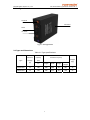
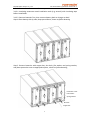
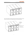
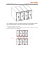
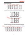
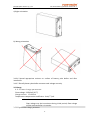
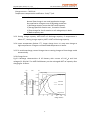
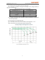
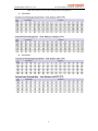
 VALVE REGULATED SEALED LEAD ACID BATTERY Intensive Cyclic Service ICS series Front Terminal Battery
OPERATION MANUAL Version:V1.1 NARADA POWER SOURCE CO., LTD Narada Power Source Co., Ltd. ICS series battery operation manual V1.1 Content CHAPTER 1 SAFETY PRECAUTIONS ................................................................................................. 2 CHAPTER 2 ICS SERIES PRODUCT INTRODUCTION .......................................................................... 4 2.1 FEATURES AND BENEFITS ...................................................................................................................... 4 2.2 MAIN APPLICATIONS ............................................................................................................................ 4 2.3 CONFIGURATION ................................................................................................................................. 5 2.4 TYPES AND DIMENSIONS ....................................................................................................................... 5 CHAPTER 3 INSTALLATION AND OPERATION .................................................................................. 6 3.1 OPERATION ENVIRONMENT ................................................................................................................... 6 3.1.1 Operation temperature range ................................................................................................ 6 3.1.2 Ventilation .............................................................................................................................. 6 3.1.2 Temperature ........................................................................................................................... 6 3.2 BATTERY OPERATION CONDITIONS ........................................................................................................... 6 3.3 STORAGE CONDITIONS .......................................................................................................................... 7 3.4 BATTERY INSTALLATION ......................................................................................................................... 7 3.4.1 Open‐package inspection ....................................................................................................... 7 3.4.2 Installation safety cautions .................................................................................................... 7 3.4.3 Install and connect battery ..................................................................................................... 8 3.5 CHARGE .......................................................................................................................................... 12 3.5.1 Float charge parameter ........................................................................................................ 12 3.6 DISCHARGE ...................................................................................................................................... 14 CHAPTER 4 MAINTENANCE ......................................................................................................... 16 4.1 MAINTENANCE STOCK TOOLS ............................................................................................................... 16 4.2 MAINTENANCE ................................................................................................................................. 16 4.2.1 Quarterly Maintenance ........................................................................................................ 16 4.2.2 Six‐month maintenance ....................................................................................................... 16 4.2.4 Two‐year maintenance ......................................................................................................... 17 4.3 REPLACE BATTERY .............................................................................................................................. 17 4.4 FAQ ANALYSIS AND SOLVING MEASURES ................................................................................................. 18 ANNEX 1 ........................................................................................................................................ 19 1
Narada Power Source Co., Ltd. ICS series battery operation manual V1.1 Chapter 1 Safety Precautions Please read the operating instructions and safety precautions to avoid accidents before you operate batteries. "Care, Caution, Warning, Danger" notification in Products and User Manual does not mean all the safety precautions to be observed, only as a supplement to safety precautions . Therefore, the operator install and operate Narada Power Source Co., Ltd.(Narada) product must be trained personnel and master the correct operating system and all the safety precautions. During operation Narada's product/ equipment, operator must comply with the safety rules in the industry, and strict compliance Narada related product/equipment safety precautions and special instructions. 1.1 High‐voltage Prohibit short‐circuit the battery terminals, a short circuit may cause the batteries burning, and may cause casualties or explosion hazard. Even without charging state, the high voltage may be present between the positive and negative terminals of the battery. Do not connect the battery positive terminal directly with any conductors, and tools such as wrenches must be insulated covered before operation. 1.2 Harmful gases Emission of harmful gases from battery may occur during the charging process or abnormal operating conditions, such as rectifier failure or high temperature. Prohibits the battery installed in an enclosed environment; Prohibits place the battery near the fire; Prohibits place the battery near flammable materials (such as a switch or fuse). Prohibit put the battery in a fire. Prohibit removal battery safety valve arbitrarily. Use safety goggles when operating batteries. 1.3 Acidic electrolytes Battery contains sulfuric acid which has a strong corrosive effect to metal and skin. Rubber gloves and apron must be used during operation of the battery in case of the 2
Narada Power Source Co., Ltd. ICS series battery operation manual V1.1 electrolyte spill. Incorrect operation may cause dangerous. Operation battery must be strictly and carefully to prevent a short circuit or battery electrolyte spill. Spilled electrolytes will corrode metal objects and circuit boards, may resulting in equipment damage and short circuit board. Be care of following matter for safety before the install and operate battery. y
Take off watches, bracelets, rings and containing metal objects ect. y
Use special insulated tools. y
Use goggle and preventive measures. y
Use rubber gloves, wear apron to prevent electrolyte spill. y
Keep terminal upward during transport, prohibit upside down
1.4 Toxic Substances Battery contains sulfuric acid, lead etc. toxic substances. Wash your hands after the operation battery. Disposal used battery in accordance with local environmental rules 1.5 Transportation Be careful during transportation and prevent severe vibration or impact for heavy lead acid battery. Place the batteries upright during transport. If the battery is dropped, the battery case may break and cause electrolyte leakage. If the battery rupture due to improper operation. Wash cloths with water immediately if electrolyte spilled on clothing. If splashed in the eyes, rinse with plenty of water and taken to hospital immediately. Please take care of the following marks: Do not put
Electricity
Protecting
Watch
With adults
danger
your eye
Short-circuits
custody
Warning
batteries into
dustbin
Read the
Fire
manual
forbidden
Circle used
3
Narada Power Source Co., Ltd. ICS series battery operation manual V1.1 Chapter 2 ICS series product introduction Narada’s ICS series battery designed to provide high cycling and fast charge performance, idea for telecom service where power supply is unstable. With innovative structure design, high quality manufacturing and high quality material, ICS batteries are also capable of PSoC, hybrid, renewable energy storage application and other cycling/standby applications. 2.1 Features and Benefits a) Extra high cycling and fast charge performance b) Designed for intensive cycle service where unstable grid power supply or no‐grid, such as Telecom BTS, hybrid genset, renewable energy storage application c) Suit for 19" or 23" and ETSI power racks/cabinets with front terminal d) 12 year design float life at 25℃ e) Wide operating temperature range ‐40℃ to +50℃ f) Superb security and reliability, more cost effective than nearest equivalent g) True front‐terminal design ‐Not requiring any additional space between the top of the battery and the next shelf ‐Easy paralleling of 48V strings (on 2 or more shelves) or 2x24V strings on one shelf via cost‐effective flexible cables running along front surface ‐With rotational symmetry not requiring expensive and long cables when long strings are assembled on multiple h) Easy installation and verification of gas collection tubing via twin front‐access gas nipples also with easy connection over several shelves i) Fold‐away handles for easy installation and removal from shelves j) Bar code tracking system to facilitate battery management. 2.2 Main applications z Telecom exchange and transmission system z Renewable energy source such as solar and wind power z Power plant and power transformer system z Navigation aid signaling system z Radio and broadcasting station z Emergency lighting system z Other standby, cyclic system 4
Narada Power Source Co., Ltd. ICS series battery operation manual V1.1 2.3 Configuration Terminal Container Cover air outlet Fig 1‐1 Configuration 2.4 Types and Dimensions Table 1‐1 Type specifications Type Nominal voltage (V) Rated capacity (Ah) Dimensions (mm) C10 Length
Width
Height
Total Height Weight (kg) ICS12V100 12 100 390 108 287 287 35 ICS12V150 12 150 546 125 310 310 55 5
Narada Power Source Co., Ltd. ICS series battery operation manual V1.1 Chapter 3 Installation and Operation 3.1 Operation environment 3.1.1 O p e rati o n te m pe rature ra nge Table 3‐1 ICS series Operation temperature rage Temperature range Recommended temperature 15℃ to 25℃ Allow temperature ‐40℃ to 50℃ Note Battery not permitted to operate at ultimate temperature for long period. Operate at high temperature for long time, battery life will reduce. Suggest operating battery at recommended temperature as possible. Notice: z Avoid heat and direct sunlight place z Avoid near water or in a wet or damp place z Avoid completely sealed space 3.1.2 Ve nt i l at i on Battery room or cabinet must be ventilation. Ordinary indoor environment do not need to take special measures to ventilation. Battery ventilation requirements for 12.5L/2V100AH/h according to EN 50272‐2 standard. If charge battery with equalization voltage, ventilation requirement should be as five times as float charge. 3.1.2 Te m pe rature ICS series are high cyclic VRLA batteries, suit for operating at 25℃ for long period. Battery must be installed in shade and dry environment, avoid heat and sun and humidity is less than 90%. 3.2 Battery operation conditions z Parallel connection: recommended no more than four banks. z Multilayer installation: the temperature difference between layer is controlled within 3℃. z Cooling conditions: space between battery no less than 10mm z Ventilation conditions: ensure hydrogen concentration is less than 0.8% z Battery mixed use: new and old battery, different brand battery do not allow mixed use z Float use: limit current ≤0.25C10A, float voltage 2.25V/cell at 25℃ z Cycle use: limit current ≤0.25C10A, charge voltage 2.35V/cell z Recommend temperature: 15℃ to 25℃, allow temperature: ‐40℃ to 50℃ 6
Narada Power Source Co., Ltd. ICS series battery operation manual V1.1 3.3 Storage conditions 3.3.1 Storage temperature range: ‐20℃ to 40℃
3.3.2 Storage battery should be fully charged. Recharge battery before use for self‐discharge during storage and transport. 3.3.3 Recharge battery during long‐term storage for self‐discharge. ICS series have shelf life of 6 months when stored at 25°C then recharge is required. Higher temperatures increase the rate of self discharge and reduce storage life. Recharge program (optional): Charge with 0.25C10A and 2.35V/cell for 24h. Table 3-2 Storage temperature vs recharge period
Storage Recharge temperature period 25℃ and below
Once every 6 months Once every 4 months Once every 3 months Once every 2 months 25~30℃ 30~35℃ 35~40℃ Recharge program
Charge with 0.25C10A and 2.35V/cell for 24h
Please avoid store battery above 40℃, otherwise affect battery life greatly. 3.3.4 Storage battery in dry, cool and ventilated environments. 3.3.5 Battery performance degradation after long‐term storage, Please shorten shelf time as possible as you can. 3.4 Battery installation 3.4.1 O p e n‐p a c k a g e inspection z Inspection: Battery appearance—no damage z Check: parts—complete z Read: Installation drawing, safety cautions 3.4.2 Installation safety ca utions 1) Fix battery, avoid vibration and shock 2) Do not put battery place where spark may be occurred (such as switch, fuse etc.) in case of hydrogen emission during charge 3) Do put battery in a sealed place or easy accumulation gas place 4) If need put battery into equipment, recommend put battery bottom of equipment to avoid temperature rise. Avoid battery contact inner wall of equipment 5) Do not put battery close to hot objects (such as transformers etc.) 6) Terminal hardware torque should be 10 to 12Nm 7
Narada Power Source Co., Ltd. ICS series battery operation manual V1.1 3.4.3 Install a n d con n e c t b atte r y 3.4.3.1 Insulating treatment metal installation tools (e.g. wrench) with insulating tape before installation. 3.4.3.2 Connect batteries first, then connect battery bank to charger or load. Step 1 Place battery side by side, keep space 10mm, shown as follow drawing Step 2 Connect batteries with copper bar, hex bolts, flat washer and spring washer, and place protective cover to appropriate place, shown as follow drawing, Protective cover Flat washer Spring washer Hex bolt Copper bar 8
Narada Power Source Co., Ltd. ICS series battery operation manual V1.1 Step 3 Connect battery with output connector with hex bolts, flat washer and spring washer, move protective cover to appropriate place, shown as follow drawing, Flat washer Spring washer Hex bolt Output connector Protective cover for output terminal
9
Narada Power Source Co., Ltd. ICS series battery operation manual V1.1 3.4.3.3 First series connection then parallel connection when multiple bank in parallel. Keep at least 10mm spaces for each layer to ensure better cooling condition. 3.4.3.4 Recommended connect mode: a) 24V system 2 layers 8 blocks (2 series 4 parallel). Series connection first, then parallel connection installation diagram Output Terminal (+) Output Terminal (‐) 10
Narada Power Source Co., Ltd. ICS series battery operation manual V1.1 b) 24V system 1 layer 8 blocks (2 series 4 parallel). Series connection first, then parallel connection installation diagram Output Terminal (+) Output Terminal (‐)
c) 48V system 2 layers 8 blocks (4 series 2 parallel). Series connection first, then parallel connection installation diagram Output Terminal (+) Output Terminal (‐) d) 48V system 1 layer 8 blocks (4 series 2 parallel). Series connection first, then parallel connection installation diagram Output Output Terminal (‐)
Terminal (+) 11
Narada Power Source Co., Ltd. ICS series battery operation manual V1.1 3.4.3.5 Battery installation orientation: a) Right orientation b) Wrong orientation 3.4.3.6 Spread appropriate antirust on surface of battery pole before and after installation. 3.4.3.7 Electrify battery bank after measure total voltage correctly. 3.5 Charge 3.5.1 F l o at c h a rge pa ra meter Float voltage: 2.25V/cell (25℃) Charge current: ≦0.25C10A Temperature compensation coefficient: ‐3mV/℃/cell Note 1: Float voltage may be inconsistent during initial period, float voltage will be consistent after six months 3.5.2 Equalization charge parameter
12
Narada Power Source Co., Ltd. ICS series battery operation manual V1.1 Equalization voltage: 2.35V/cell Charge current: ≦0.25C10A Temperature compensation coefficient: ‐5mV/℃/cell Note 2: Normal float charge is not need equalization charge. Do equalization charge as one of following conditions: 1) Discharge capacity more than 20% rated capacity. 2) Storage period 6 months max., 3 months is better. 3) Float charge for 3 to 6 months or cell voltage drop in bank. 4) Before capacity test. 3.5.3 Setting charge capacity 105%‐110% of discharge capacity. If temperature is below 5℃, Setting charge capacity 110% ~120% of discharge capacity. 3.5.4 Lower temperature (below 5℃), longer charge time. It is easy over‐charge at high temperature. Charge at recommended temperature is better. 3.5.5 To avoid overcharge, control charge time or setting change to float charge mode automatically. 3.5.6 Charge Curve Fig.2‐2 Recharge characteristics of ICS battery with current of 0.1C10A and limit voltage of 2.35V/cell. The 100% DOD battery can be recharged 105% of capacity after charging for 24 hours. (%)
120
(V)
(CA)
Charge Voltage
2.35
Charge Capacity
100
40
0.05
Charge
Voltage
60
0.10
Charge
Current
Charge
Capacity
2.25
80
2.15
100% DOD
50% DOD
2.05
1.95
20
Charge Current
0
0.00
0
4
8
12
16
20
Charge Time(h)
13
24
Narada Power Source Co., Ltd. ICS series battery operation manual V1.1 3.6 Discharge 3.6.1. No more than 3C10A during continuous discharge 3.6.2. Discharge end voltage is varying with discharge current; voltage should not lower than specified value. Table 3‐3 Discharge current vs. end voltage End voltage(V/cell) Discharge current(A) <0.1C10 1.9 1.8 ≈0.1C10 1.8 ≈0.17C10 1.8 ≈0.25C10 1.7 ≧0.6C10 3.6.3. Charge immediately after discharge. Charge immediately if unexpected over‐discharge happen. 3.6.4. Discharge curve and discharge data Fig. 3‐2 Discharge Performance Curves at Different Discharge Rates(25℃) Table 3‐4 Constant current and constant power discharge data Discharge voltage vs discharge time curve(25℃) Discharge voltage(V) Minutes
Hours Fig 3-2 Discharge characteristic curve
14
Narada Power Source Co., Ltd. ICS series battery operation manual V1.1 Table 3‐4 Constant current and constant power discharge data a) ICS12V100 b) ICS12V150 15
Narada Power Source Co., Ltd. ICS series battery operation manual V1.1 Chapter 4 Maintenance 4.1 Maintenance stock tools Following tools and equipments are necessary at least to maintenance and troubleshooting VRLA batteries. 1. Digital multimeter 2. Wrenches insulated 3. Adjustable wrench insulated 4. Torque wrench 5. Rubber gloves 6. Full set of masks 7. Plastic apron 8. Portable eyedrops 9. Fire extinguishers (C grade) The following equipment is optional according to the type of maintenance. 1. Resistance tester 2. Charger and discharger special for storage battery (portable) 4.2 Maintenance In order to assure service life, the batteries should be correctly inspected and maintained. The maintenance methods of ICS series batteries are recommended as follows: 4.2.1 Q u a r te r ly Mainte nance 1) Keep the battery‐room clean, no garbage and good light 2) Ensure all the safety equips are complete and available, especially ensure battery management parameter settings are normal 3) Measure and record ambient temperature of the battery‐room 4) Visually inspect battery a. Cleanliness b. Damage and overheat trace of terminal c. Shell or cover damage d. Overheating traces 5) Measure and record float voltage and equalization voltage of system 6) Measure and record float voltage and equalization voltage each cell 7) Measuring DC voltage each battery polarity to detect ground faults 8) If possible, measure and record battery system DC and AC float current 9) Measure and record control equip temperature. Measure and record battery temperature in the center of side or negative post. 4.2.2 S i x‐ month m a i nte n a n c e 1) Repeat quarterly maintenance 2) Measure and record each cell internal resistance to anomaly battery trends and detection of individual cells deviation from normal cells. 4.2.3 Yearly maintenance 16
Narada Power Source Co., Ltd. ICS series battery operation manual V1.1 1) Repeat six‐month maintenance 2) Re‐tightening all connectors between cells 4.2.4 Two ‐yea r mainte nance Do capacity test every two‐year, or choose discharge rate according to load. Test process as following: Charge battery fully, rest 5h‐24h at 25±2℃, then discharge battery with current to end voltage shown in table 4‐1, record discharge voltage and time. Table 4‐1 Discharge current and end voltage Discharge Discharge End voltage Capacity rate (V/cell) current(A)
10HR I10 1.80 C10=1.00C10 8HR 1.80 1.15I10 C8=0.92C10 5HR 1.80 1.78 I10 C5=0.89C10 3HR 2.5 I10 1.80 C3=0.75C10 1HR 1.75 5.5 I10 C1=0.55C10 Standard Capacity temperature is base on 25℃, Convert the testing capacity(Cr) to standard capacity(Ce) according to formula if test temperature is not 25℃ Ce =
Cr
1 + k ( t − 25 )
Wherein:t- ambient temperature during discharging k-temperature coefficient: 10hhr rate discharge,k=0.006/℃ 5~8hr rate discharge,k=0.007/℃ 3hr rate discharge, k=0.008/℃ 1hr rate discharge, k=0.01/℃ If standard capacity (Ce) is less than 80% rated capacity, please contact manufacturer to analyze the reasons for the reduction in capacity. 4.3 Replace battery 4.3.1 If standard capacity is less than 80% rated capacity (see clause 4.2.4 test method), user should consider replacing battery. In some special cycle mode, user can replace battery until lower capacity according to practical situations. 4.3.2 Replace period Storage battery is belong to consumables with certain life cycle. Recommend replace the old battery with the new one before battery design service life to ensure system safety. 17
Narada Power Source Co., Ltd. ICS series battery operation manual V1.1 No. FAQ 1 High float Voltage variation 2 Battery can’t be charged and discharged 3 Reverse polarity /broken There are white crystal in terminal or valve ports Electrolyte leakage processing method 1. Check if setting parameter are right 2. Replace cell which’s float voltage lower than 2.18Vpc with the new batter. New and old batteries production data should be no more than 6 months. If one in third float voltage lower than 2.18Vpc, then replace whole strings batteries. 3. Discharge battery with 100% DOD after replace, effect will be obvious 1. Check battery connection, ensure no loose connector, corrosion, cut, reversal connection. 2. Check the battery whether leaking, bulging, cracking happen 3. If no above abnormal occurrence, then test open circuit voltage (OCV) after rest 30min, if cell’s OCV less than 2.08Vpc, replace it. Replace reverse polarity battery Replace broken battery If it is false leaking, clean white crystals with a soft cloth dipped with soapy water, then wipe it dry with a dry soft cloth. You can 4 also wipe with a soft dry cloth directly. Be careful not to plug the valve port. If battery leakage, replace it and clean corrosion rack and 5 ground. Replace the battery with serious bulge immediately. If battery only Slight bulging (the sidewall bulge size 5mm‐10mm), handle it as following: 1. Check whether battery outlet of safety valve cover plate is blocked, if blocked, replace the cover plate or clean obstruction. Battery bulge If no hole in cover plate, replace it immediately. 6 2. Check whether the cell voltage is too low (below 2.08V) or or crack reverse connection battery. 3. If it is no cause of clause 1 and 2, then check system voltage sitting, if too high, adjust the setting parameters. Open valve for a while to let internal gas escape after disconnect the circuit with special tools. For more information, visit our website at www.naradapower.com, or contact us: Email: [email protected] Tel: (+86‐571)56975980 / 56975956 Fax: (+86‐571)56975955 18
ICS series operation manual – V1.1–N‐ EN Feb. 2014 – Subject to revision without prior notice E.&O.E. 4.4 FAQ analysis and solving measures Narada Power Source Co., Ltd. ICS series battery operation manual V1.1 Annex 1 VRLA Battery Regular Maintenance Record Type Place Status Number of battery Temperature Total Voltage(V) Current (A) No. No. Voltage(V) 1 13 2 14 3 15 4 16 5 17 6 18 7 19 8 20 9 21 10 22 11 23 12 24 Check by sight Result: Tester: Date: 19
Voltage(V)


![[输入书名]](http://vs1.manualzilla.com/store/data/005783394_1-fc20c72617a19a0d7587a472ef1576a7-150x150.png)