1
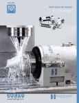
ROTARY
Rotary Tables
Indexers
and Trunnions
TURNING
MILLING
GRINDING WORKHOLDING ROTARY
www.hardinge.com
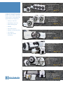
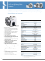
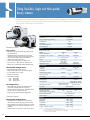
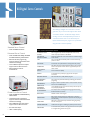
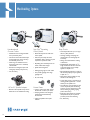
Hardinge Rotary Product Lineup
More Accuracy, Speed and Flexibility!
The Most Flexible Quick-Change Workholding Concept on the Market…
Hardinge’s A2-4 (5C) and A2-5 (16C) spindle nose designs allow quick change between collets, expanding
collets, step chucks, 3-jaw chucks and face plates. Common spindle tooling can be shared between the
Hardinge Rotary System(s) and a lathe. The gripping is in the spindle, closest to the spindle bearings, unlike
surface-mounted adapters used on traditional rotary tables. Multiple workholding options provide alternate
gripping solutions for increased precision and capability.
Pages 24-25
2
800.843.8801 www.shophardinge.com
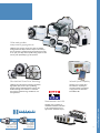
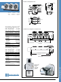
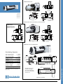
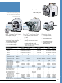
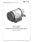
5C2 Gear-Driven Rotary Indexers
GD5C2 single
GD5C2-02 dual
GD5C2-03 triple
GD5C2-04 quad
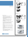
Hardinge has a large selection of rotary
products for all ranges of production.
Choose from precision and superprecision systems – single-spindle, multispindle and dual-axis configurations…
• Accuracy to ±3 Arc-Sec
16C2 and 3J2
Gear-Driven Rotary Indexers
GD16C2 and GD3J2 single
GD16C2-02 and GD3J2-02 dual
GD16C2-03 and GD3J2-03 triple
• Repeatability to ±2 Arc-Sec
• Rapid positioning speeds
pages 8 - 9
pages 10 - 11
• Reliability
• Zero backlash systems
• Flexibility of workholding tooling
• Fast changeover
• Heavy axial and radial
load capacity
160 and 210mm
Low-Profile Rotary Tables
GD160LP
GD210LP
pages 12 - 13
Tilting Dual-Axis Rotary Indexers
Single and Multi-Spindle
LPX5C2-01 single
LPX5C2-02 dual
LPX5C2-03 triple
LPX5C2-04 quad
GDX5C2
pages 14 - 15
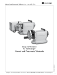
Gearless, Direct-Drive, Zerobacklash Rotary Table Indexers
DD100
DD200
DD300
pages 16 - 17
pages 18 - 27
3
www.shophardinge.com
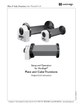
Plate and Cube Trunnions, Servo
Controls, Collet Closers, Tailstocks
and Workholding Options
Quality Manufacturing Processes
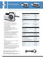
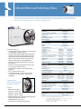
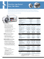
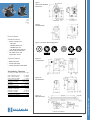
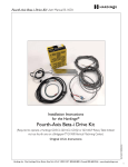
Hardinge's GD5C2 has more accuracy, more spindle clearance and more thrust & radial load. All rotary products are
manufactured in Elmira, New York to strict specifications.
Curved front casting and removable
handle for increased spindle
clearance and better tool access.
10 arc-sec Repeatability
±25 arc-sec Accuracy
.0002" Max. Runout (.005mm TIR)
Robust, dual-bearing spindle for
heavier radial and axial loads.
50-lb (23kg) part weight and 1000-lb
(4448N) tailstock thrust per spindle is
not a problem – even on a quad unit
with tailstocks!
1
4
6
2
4
5
3
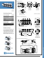
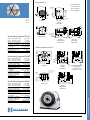
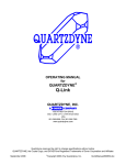
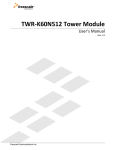
Small body. INTENSE soul & character.
Hardinge next-generation 5C2 mechanically outmaneuvers the competition.
®
1. HOUSING
4. DOUBLE ECCENTRICS
6. CROSS AXIS HELICAL GEAR
Machined and bored on a Dixi 280 precision CNC jig
boring machine for close tolerance finish dimensions.
Foundry castings (made in the USA) provide vibration
damping.
Double eccentrics (not single) provide the finest gear
mesh adjustment. Hardinge has lowered the backlash
range and improved accuracy overall. Customers can
perform future gear wear compensation for extended
life and improved accuracy over time.
Hardened & ground steel cross-axis helical gear offers
more accuracy and less wear. The process begins on
a Hardinge Super-Precision CNC lathe, then hobbed
on a Koepfer hobber, with the final finish grind on a
Samputensili threaded wheel grinder. Grind quality
of AGMA class 13 is verified on a Wenzel CNC gear
inspection machine.
2. SPINDLE
Spindle is finish ground on a high-precision
Kellenberger® CNC universal grinding machine. All surfaces where bearings and gears are installed are ground
in the same setup for maximum accuracy.
3. BEARINGS
High-load, tapered dual roller bearings are used to support heavy radial and axial loads and to provide a longer
spindle life.
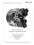
THE EVOLUTION
OF THE HARDINGE
5C2 ROTARY SYSTEM
4
5. WORM DRIVE SHAFT
Hardened and ground steel worm drive shaft is standard.
The process begins on a Hardinge® Super-Precision
CNC lathe and the threads are finish ground on a
Drake thread grinder. Grind quality of AGMA class 13
is verified on a Wenzel CNC gear inspection machine.
SEALING
Hardinge has an extremely thorough seal system to
keep coolant out.
MULTIPLE PART SETUPS
INSPECTION
Final inspection of every unit is performed using a
Heidenhain encoder mounted directly on the spindle
nose to assure final positioning accuracy and repeatability. Printout of accuracy is shipped with each unit.
Choose from dual, triple and quad units for processing multiple parts to increase output. All spindles are
synchronized for aligned part orientation within .0002"
(.005mm).
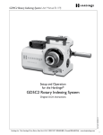
1901
1940
1940's
1960's
Hardinge
manufactures the
5C Collet
Hardinge
manufactures and
introduces the 5C
"threaded-nose" spindle
Hardinge
manufactures a
5C dividing head
Hardinge
manufactures 5C manual
indexers using Hardinge's threadednose spindle & collet closer design
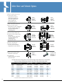
Collet-ready spindles
accept several gripping devices
Hardinge rotary systems accept many styles of standard
tooling without an adapter, which is unique in the industry.
You can purchase a complete system all tooled up and ready
to run your parts. Rely on the spindle tooling experts for the
accuracy and repeatability to get the job done.
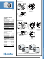
Zero-backlash Direct-Drive Technology
Infrared Upload Capability
Hardinge offers direct-drive technology for flexible,
high-speed, super-precision parts positioning.
Features include rapid bidirectional response, zero
backlash and high servo stiffness in a small foot
print. Custom-manufacturing is available for twoaxis applications.
Hardinge servo controls have
infrared sensor capability for
convenient upload or download
of programs from a Windowsbased Pocket PC.
Manufactured in the USA
2004
2007
Hardinge
manufactures
5C Rotary Systems based on
1960's mechanical design
Hardinge
manufactures and introduces
the next-generation
5C2 Rotary System
5
www.shophardinge.com
Hardinge rotary products are
manufactured in Elmira, New York
to strict specifications and are
approved for worldwide export.
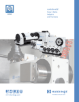
4th-Axis Integration…interfacing to a host machine
Direct-Drive
DD300 Rotary
Table Indexer
mounted in a
Bridgeport®
vertical machining
center machining
an out-of-round,
elliptical part.
Trunnion tailstock
application for the
DD100 High-Speed
Direct-Drive
Rotary Positioner.
Spiral milling
application on
a Bridgeport
knee mill using a
5C2 indexer and
manual tailstock.
6
True 4th-Axis* via the host machine (gear-driven)
Hardinge gear-driven rotary systems may be connected directly to the host machine
and its CNC control. Connecting to the machine's CNC control requires replacing
the standard servo motor and cable with a servo motor and cable that is compatible
with the host CNC. If the machine is not 4th-axis ready, the machine will need a
4th-axis option and servo amplifier installed. Hardinge has integrated its rotary products
with Fanuc, Siemens, Heidenhain, Okuma and Milltronics. Other systems can be supported
with the assistance of our engineering team and your machine distributor or manufacturer.
Configured as a 4th-axis, the Hardinge Rotary System operates in a fully interpolated
fashion with the other axes of the host machine. This arrangement does not use the
Hardinge Servo Control but relies on the capabilities of the machine's CNC control and
its motor amplifier. The programming requirements for the rotary system become fully
integrated into the main CNC program and is treated as a 4th axis* of the machining
center. The system effectively becomes an integral part of the host machine.
4th-Axis* via RS-232 port and interface cable
(program resides in the host machine)
The Hardinge gear-driven rotary systems (rotary unit and servo control) may be
connected to the host machine via the RS-232 port. Using this method, the program
commands will be resident in the machine’s CNC control and sent directly to the
Hardinge Servo Control. This interfacing technique requires that the host CNC be
capable of communicating programming information over an RS-232 communications
port during program execution.
After passing the command information to the servo control, the host CNC will trigger
movement to occur via the four-wire interconnecting cable as described in the chart to
the left. The cable is provided with a connector for the Hardinge control side and wire
terminations for the CNC side. Configuring to the Fanuc control is fully supported.
Other control types may be considered upon request. Please note that control systems
that do not directly provide the ability to write information to the RS-232 port may
require special software by the control builder in order to operate in this fashion. The
RS-232 cable is to be provided by the customer. A total of nine control units can be
daisy-chained together for program transfer – each with a distinct identifier.
Interface Cable
for Options #2 and #3
Function
Wiring to the host CNC
Cycle Start command to indexer
via M-code output, relay
(pins 3 and 4 of Hardinge connector)
Spare M-code output
and associated relay
24 volt supply
(pin 1 of Hardinge connector)
To power supply
M-code finish signal
(pin 2 of Hardinge connector)
Spare M-code input
In this interface arrangement, the communication that occurs between the Hardinge
all-digital servo control and the host CNC is in the simplest form. Logically the host
CNC requests that the rotary system control process its next programmed commands
and then advise when completed. This requires that the program be stored internally
within the Hardinge servo control, which is then asked to execute the commands
sequentially as a signal is received from the host CNC control. Typically the START
rotary command is prompted by a spare and programmable M-Code. At the completion
of the rotary-commanded movement, the unit sends the host CNC a finished signal
so that the VMC can proceed with the remainder of its program. The interface cable
is provided to connect the host machine to the Hardinge servo control. Note that not
all CNC machines have spare relays and M-codes as standard.
1
INTERFACE
OPTION
2
INTERFACE
OPTION
3
A "Y" cable is available for connecting a Haas brush motor indexing head to a specificallyconfigured Hardinge all-digital Servo Control.
True 4th-Axis* via the host machine (direct-drive)
Hardinge direct-drive rotary systems incorporate a high-energy, rare-earth
torque motor and are generally supported as a true 4th-axis by Fanuc on
the higher level controls such as the 21i, 18i, etc. Pole position detect is
required. Some machine tool builders use Fanuc controls but do not
include support for all Fanuc options in their use of the control. Hardinge DirectDrive Rotary Systems have also been installed on Heidenhain CNC machines using
high voltage drives. Ladder modificaitons may be required. Contact the Hardinge Rotary Systems sales group at 800-843-8801 for more information.
The DD100 and DD200 Direct-Drive Rotary Systems can be used with the all-digital
direct-drive servo control or integrated into your CNC manufacturing application as a
true 4th-axis. The DD300 is connected via true 4th-axis integration only.
INTERFACE
OPTION
4
Note: Continuous rotation is not supported on Bridgeport Fanuc controls.
7
www.shophardinge.com
*4th Axis is a generalized term referring
to an additional axis that can be integrated
into the current X, Y and Z axes
machining center configuration.
4th-Axis* via CNC interface cable (program resides in the
Servo Control)
INTERFACE
OPTION
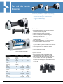
5C2 Rotary Indexers
The 5C2 Rotary System is based on a long history of Hardinge 5C spindle and manual indexer designs. Over 60 years of
Hardinge-engineered and proven mechanical elements guarantee an accurate, repeatable, reliable and flexible product.
SERVO CONTROL / PROGRAMMING
Servo Model
Standard Servo
Storage - Number of programs/steps
up to 50/1000
RS-232 Interface
YES
Text Display
multiple lines
Infrared Upload/Download
Baud Rate Capacity
YES
up to 56K
SPINDLE
Runout Maximum (TIR)
Standard Features
• Curved front casting and removable handle for
increased spindle clearance and better tool access
• Rapid indexing speed up to 360° per second
• ±5 arc-sec Repeatability
• ±25 arc sec Accuracy
• .0002" (.005mm) Maximum runout (TIR)
• Robust, dual-bearing spindle accommodates heavy
axial and radial loads with the ability to run a triple
or quad unit with tailstocks
• Brushless motor
• Industry compatible – same spindle centerline, foot print
and tool clearance as previous Hardinge products and
other US-made brands for direct replacement
• Single, dual, triple and quad spindle configurations
• Operate with the Hardinge all-digital servo control
or interface to your machine
• Uses standard 5C collets, Sure-Grip® expanding collets,
step chucks and manual jaw chucks
0.0002" (.005)
Backlash
40 arc-sec
Speed
Maximum RPM Rapid Min-
0.001 to 360° per sec
1
Load Support – max. part weight
Spindle Type
Collets
Spindle center to base
• Collet closers – manual, pneumatic fail-safe through-hole
and pneumatic high-force
• Tailstocks and plate trunnions
• Quill Switch for Bridgeport® knee mill to automate the
indexing process
• Manual drawbar for each spindle for multi-spindle units
• Preset tailstock and indexer combinations – self-contained
units mounted on a subplate for easy placement on and off
the machine table to maintain factory tolerances
• Complete array of Hardinge spindle tooling
Preset Tailstock and Rotary Combinations
SINGLE: Pneumatic Tailstock with valve, Pneumatic Rotary Unit,
Double Mounting Plate and Servo Control
DUAL: Two Pneumatic Tailstocks with valving, Dual-unit
Pneumatic Rotary Unit, Double Mounting Plate and Servo Control
8
23/16 – 10 threaded nose
Standard 5C
4.000" ± 0.001 (101.6 ±.0254)
POSITIONING
Accuracy (arc-sec)
±25 arc-sec
Repeatability
±5 arc-sec
Resolution (degree)
Max Rotation/Step (degree) 7
Gear Diameter
0.001
9999.99
2.8" (71.1)
MOTOR
Type (DC servo)
0.78hp / 0.58KW
Torque at Spindle
54 ft-lb / 73 Nm
Duty Cycle
90% at full speed
OPERATING SPECIFICATIONS
Gear Ratio (worm & gear)
Operating Temp. (maximum ambient)
Power Requirements (VAC)
Options
60
Dual Bearing 50 lb / 23 kg
60:1
120°F / 49°C
115 +/- 5% @ 10 amps
Max Air Pressure using High-Force Collet Closer
120 psi / 8.3 bar
Max Air Pressure using Fail-Safe Collet Closer
85 psi / 5.8 bar
WEIGHT
Single Indexer
55 lb / 25 kg
Dual Indexer
119 lb / 54 kg
Triple Indexer
179 lb / 81 kg
Quad Indexer
240 lb / 109 kg
Control
Note: 7 – continuous rotation available
10 lb / 4.5 kg
GD5C2 Dimensions:
7.98 (203)
.51 (13)
1.18 (30)
7.75 (197)
7.24
(184)
6.73 (171)
2.67 (68)
15.40 (391)
GD5C2
GD5C2-02
GD5C2-03
GD5C2-04
Slotted face plates can be used for "light duty"
off-center work only.
Bridgeport Knee Mill
Remote Quill Switch
A remote quill switch is available for use
with manual Bridgeport® mills. When
the quill handle is retracted, it touches
a micro switch for automatic indexing,
eliminating the need to push the start
button on the servo control. The
bracket and interface cable are included.
1.75 (44)
3±.0003
(76±.007)
.75 (19)
5.47
(139)
Side View
with Manual
Collet Closer
1.22 (31)
Back View
with Manual
Collet Closer
4.44 (113)
3±.0003 (76)
Workholding Capacities
Collets – Round (max. capacity)
11/16" (26.98)
29
Collets – Hex (max. capacity) /32" (23.01)
3
Collets – Square (max. capacity) /4" (19.05)
Step Chucks – Regular Depth up to 6" (152.4)
Step Chucks – Extra Depth
up to 6" (152.4)
3-Jaw Chuck
5" (127)
3-Jaw Chuck
6" (152.4)
Sure-Grip® Expanding Collets 1/8" - 3" (3.17 - 76.2)
Fixture Plate – Spindle Mount 3" (76.2)
Fixture Plate – Spindle Mount 5" (127)
Fixture Plate – Collet Style 33/8" (85.72)
Fixture Plate – Collet Style 43/8" (111.12)
Slotted Face Plate (diameter)
7" (178)
Collet Stops for part positioning
YES
3±.0003
(76±.0076)
2.25 (57)
7 (178)
.5 (12.8)
3.26 (83)
4±.001
(101.6±.025)
Oil Drain
Plug
5/8" or 18mm
locating pins
(millimeters in parentheses)
Front and Bottom Views
GD5C2-02, -03 and -04 Dimensions:
5 (127)
9.64 (245)
7.98 (203)
5 (127)
5 (127)
.72 (18)
10.13
(257)
1.88
(48)
5.88
(149)
.88 (22)
0.53 (13)
4.25 (108)
15.88 (403) Dual-Unit; 20.88 (530) Triple-Unit
27.24 (692) Quad-Unit
8.50 (216)
Dual/Triple Side View
with Pneumatic HighForce Collet Closer
Front View
Dual/Triple Plates
Quad Plate
8.01
(203)
Quad
.98 (25)
Quad
10.25 (260) Dual-Unit
16.25 (387) Triple-Unit
.48 (12)
Others
0.53 (13)
2.75 (70)
22.97 (583) Quad-Unit
Bottom View
5.50
(140)
Quad Side View
with Pneumatic HighForce Collet Closer
Preset Tailstock and Indexer Dimensions:
2.51 (64)
1.88
(48)
9.51
(242)
Dual
Triple
12 (305)
29.48 (749)
Front View
2.28 (58)
15.82 (402)
10.23
(260)
5
(127)
Bottom View
9
www.shophardinge.com
16.85
(428)
16C2 and 3J2 Rotary Table
Indexers
Hardinge's world-renowned collet-ready A2-5 spindle is the heart of the system. The same accuracy, precision and
reliability built into the Hardinge lathe extends to a large capacity rotary indexer. A variety of standard 16C or 3J
spindle tooling will mount directly in or on the spindle without the use of an adapter. Common spindle tooling can
now be shared between a rotary unit and a lathe.
SERVO CONTROL / PROGRAMMING
Servo Model
Enhanced Servo
Storage - Number of programs/steps
RS-232 Interface
YES
Text Display
multiple lines
Infrared Upload/Download
Slotted faceplate
sold separately.
Standard Features
Baud Rate Capacity
Runout Maximum (TIR)
• A2-5 16C or 3J spindle accepts standard collets,
Sure-Grip® expanding collets, step chucks, fixture
plates and power chucks
•
•
•
•
•
•
Load Support
Maximum part weight
•
•
•
•
•
•
•
Options
• 5C adapter available for small part processing –
Order part no. CJ 00002835CA
• Tailstocks, plate and cube trunnions
• Complete array of Hardinge spindle tooling
YES
up to 56K
SPINDLE
Backlash
Typical part handling of 5 x 7" (127 x 178) parts
Rapid indexing speed up to 300° per second
±5 arc-sec Repeatability
±15 arc sec Accuracy
.0002" (.005mm) Maximum runout (TIR)
Robust, dual-bearing spindle accommodates heavy
axial and radial loads with the ability to run a dual
or triple unit with tailstocks
Spindle clamp eliminates slippage when performing
heavy off-center drilling
Pneumatic collet closer provides 3987-pound
(1808kg) draw bar pull at 100psi
6" (152.4) centerline to base
.6248" (15.87) total drawbar travel suitable for
3-jaw power chucks
Through-hole: 16C2 - 1.624" (41.25), 3J2 - 1.75" (4.45)
Performs spiral, arc and linear milling as well as
standard indexing operations
Single, dual and triple spindle configurations
up to 50/1000
0.0002" (.005)
40 arc-sec
Speed
Maximum RPM Rapid Min-
0.001 to 300° per sec
1
Spindle Type
Collets
Spindle center to base
50
Dual Angular Contact Bearing
150 lb / 68 kg
A2-5
Standard 16C / Standard 3J
6.000" ± 0.001
(152.4 ±.0254)
POSITIONING
Accuracy 6
±15 arc-sec
Repeatability
±5 arc-sec
Resolution (degree)
Max Rotation/Step (degree) 7
Gear Diameter (inch/mm)
0.001
9999.99
6.2 (157)
MOTOR
Type (DC servo)
0.78 hp / 0.58kW
Clamping Torque 1
175 ft-lb / 237 Nm
Torque at Spindle
70 ft-lb / 95 Nm
Duty Cycle
90% at full speed
OPERATING SPECIFICATIONS
Gear Ratio (worm & gear)
Operating Temp. (maximum ambient)
Power Requirements (VAC)
60:1
120°F/49°C
115 +/- 5% @ 10 amps
Maximum Air Pressure
120 psi / 8.3 bar
Minimum Air Pressure
85 psi / 5.8 bar
WEIGHT
Single Indexer
200 lb / 90.7 kg
Dual Indexer
520 lb / 235.8 kg
Triple Indexer
627 lb / 284.4 kg
Control
9.54 lb / 4.34 kg
Notes: 1 – maximum torque applied before slipping occurs
6 – accuracies can be improved with electronic compensation
7 – continuous rotation available
10
GD16C2 and GD3J2 Dimensions:
11.49 (292)
0.86 (21.8)
12.12 (308)
6±.001
(152±.025)
SINGLEGD16C2 GD3J2
DUAL GD16C2-02GD3J2-02
TRIPLEGD16C2-03GD3J2-03
15.70 (399)
4±.0003
(102±.008)
4.80 (122)
9.48 (241)
9.4 (239)
Side View
Front View
2 (51)
.74 (19)
4±.0003 (102±.008)
7.63 (194)
Bottom View
Workholding Capacities 16C2
Collets – Round (max. capacity) 15/8" (41.27)
Collets – Hex (max. capacity)
113/32" (35.71)
Collets – Square (max. capacity) 19/64" (28.97)
Step Chucks – Regular Depth up to 6" (152.4)
Step Chucks – Extra Depth
up to 6" (152.4)
FlexC Collet System - Style D
29/16" (65.00)
3-Jaw Chucks (diameter)
5", 6", 8"
Sure-Grip® Expanding Collets 1/2" - 4" (12.70 - 101.6)
Collet Style 1/8" - 4" (3.17 - 101.6)
Spindle Style
Fixture Plates
Spindle Mount
51/2" (139.70)
Spindle Mount
87/8" (225.42)
Collet Style 63/8" (161.92)
Slotted Face Plate 8.85" (225)
Slotted Face Plate
10" (254)
Collet Stops for part positioning
YES
GD16C2-02, -03, GD3J2-02 and -03 Dimensions:
13.62
(346)
7.87±.01
(200±.25)
1 (25.4)
10±.01
(254±.25)
10±.01
(254±.25)
39.09 (993) Triple; 29.09 (739) Dual
Front View
Workholding Capacities 3J2
Collets – Round (max. capacity) 13/4" (44.45)
Collets – Hex (max. capacity) 117/32" (38.89)
Collets – Square (max. capacity) 11/4" (31.75)
Step Chucks – Regular Depth up to 6" (152.4)
FlexC Collet System - Style D
29/16" (65.00)
3-Jaw Chucks
5", 6"
Sure-Grip® Expanding Collets
1/2" - 4" (12.70 - 101.6)
Collet Style
1/8" - 4" (3.17 - 101.6)
Spindle Style
Fixture Plates
Spindle Mount 51/2" (139.70)
Spindle Mount
87/8" (225.42)
Slotted Face Plate 8.85" (225)
Slotted Face Plate
10" (254)
Collet Stops for part positioning
YES
1.89 (48)
11.57
(294)
.53 (13.49)
9.52
(242)
31.93 (811) Triple; 20.98 (533) Dual
33.89 (861) Triple; 23.77 (604) Dual
Bottom View
11
www.shophardinge.com
Top view of 16C2
Rotary Indexer –
Configure
for either leftor right-hand
application.
160 and 210mm Low-Profile Rotary Tables
Sleek, fast and accurate. Engineered to support heavy loads and high-force cutting applications while maintaining
accuracy over a long life. Fast clamp and release in milliseconds gives you increased parts-per-hour. Hardinge rotary
tables have collet-ready spindles for increased part gripping options.
GD160LP
GD210LP
SERVO CONTROL / PROGRAMMING
Servo Model
Standard Servo
Storage - Number of programs/steps
up to 50/1000
RS-232 Interface
YES
Text Display
multiple lines
Infrared Upload/Download
YES
Baud Rate Capacity
up to 56K
SPINDLE
Runout Maximum (TIR)
Face plate included
Standard Features
• 160 and 210mm slotted face plates are precision ground
on a Kellenberger® grinding machine
• A2-4 (GD160LP) and A2-5 (GD210LP) extended-nose
spindles accept collets, expanding collets, step chucks,
manual chucks, power chucks and slotted face plates
• Built-in clamp to handle off-center drilling, cross-axis
milling and other high-force cutting applications
• Fast clamp and release in milliseconds for increased
parts-per-hour
• Hardened steel worm and hardened steel worm gear
for long life and continued accuracy
• Double eccentric design for finest possible factory
gear mesh
• Left- or right-hand motor mount
• Use with all-digital servo control on most brands
of machines, or as 4th-axis (Fanuc, Siemens, Haas,
Heidenhain)
Extended-nose
spindle design provides
optimum clearance.
Options
12
0.0002" (.005)
Backlash
40 arc-sec
Speed
0.001 to 240° per sec
Maximum RPM Rapid Min-
40
1
Load Support
Maximum part weight
Spindle Type
Table Diameter
Thru Diameter Face Plate (maximum)
Dual Bearing
100 lb / 45 kg
Dual Bearing
220 lb / 100kg
A2-4
A2-5
6.299" (160)
8.267" (210)
1" or 25mm choice
2" or 50mm choice
Thru Dia. Opt. Collet Closer (max)
1.08" (27.4)
1.62" (41.27)
Width of T-slot
.44" (11.2)
.57" (14.4)
Collets
Standard 5C
Standard 16C
5.000" ± 0.001
(127 ±.0254)
6.000" ± 0.001
(152.4 ±.0254)
±20 arc-sec
±15 arc-sec
Spindle center to base
POSITIONING
Accuracy 6
Repeatability
±5 arc-sec
Resolution (degree)
0.001
Max Rotation/Step (degree) 7
Gear Diameter (inch/mm)
9999.99
3.7 (94)
6.2 (157)
MOTOR
Type (DC servo)
0.78 hp / 0.58kW
2.0 hp / 1.50 kW
Clamping Torque 2 (pneumatic)
150 ft-lb / 203 Nm
275 ft-lb / 373 Nm
73 ft-lb / 99 Nm
90 ft-lb / 122 Nm
Torque 3 at Spindle
Duty Cycle
90% at full speed
OPERATING SPECIFICATIONS
Gear Ratio (worm, gear & timing belt)
90:1
Operating Temp. (maximum ambient)
120°F/49°C
Power Requirements (VAC)
115 +/- 5% @ 10 amps
Maximum Air Pressure
100 psi / 6.9 bar
• Pneumatic Collet Closer
(draw bar force at 80 psi)
Minimum Air Pressure
85 psi / 5.8 bar
GD160LP – 1850 lb / 835 kg
GD210LP – 3191 lb / 1440 kg
• GD210LP available with or without collet-ready spindle
• Tailstocks, plate and cube trunnions
(GD160LP plate trunnion only)
• Complete array of Hardinge spindle tooling
Rotary Table
WEIGHT
Control
Notes:
120 lb / 57 kg
200 lb / 90.7 kg
9.54 lb / 4.34 kg
2 – maximum torque applied before slipping occurs
3 – from standard GE Fanuc H104 amplifier (results vary when using servo
control box or 220v power source)
6 – accuracies can be improved with electronic compensation
7 – continuous rotation available
GD160LP Dimensions:
8.40 (213)
6.30 (160.0)
Thru
Spindle
1.25
(31.7)
MADE IN U.S.A.
5 (127)
4.44
(112.9)
11.61 (294.9)
GD160LP
GD210LP
16.05 (407.8)
10.35
(262.9)
w/Collet
Closer
1.063
(27.0) 1.25 (33)
±.001 (.025)
Plate
1 or
(25)
Front View
3.45
(88)
2.31 (59)
5.87 (149)
Side View shown
with optional Pneumatic
Collet Closer
4.123 (104.7)
.531 (13.5)
Workholding Capacities
GD160LP
Collets – Round (max. capacity) 11/16" (26.98)
29/32" (23.01)
Collets – Hex (max. capacity) 3/4" (19.05)
Collets – Square (max. capacity) Step Chucks – Regular Depth up to 4" (101.6)
Step Chucks – Extra Depth
up to 4" (101.6)
Sure-Grip® Expanding Collets 1/8" - 3" (3.17 - 76.2)
3-Jaw Manual Chuck
5" (127)
3-Jaw Manual Chuck
6" (152.4
3-Jaw Sure-Grip® Power Chuck
4" (101.6)
Fixture Plate – Collet Style 33/8" (85.72)
Fixture Plate – Collet Style 43/8" (111.12)
Slotted Face Plate (diameter)
6.3" (160)
Collet Stops for part positioning
YES
Bottom View
GD210LP Dimensions:
9.15 (232.5)
8.26 (210)
4.01
(101.9)
9.15 (232.5)
Plate
2 or (50)
MADE IN U.S.A.
6 (152.4)
±.001 (.025)
14.79 (375.8)
4.75 (120.8)
19.86 (504.4)
Thru
Spindle
1.88
(47.7)
12.65
(321.3)
w/Collet
Closer
1.625
(41.3)
w/Plate
2 or (50)
Front View
1.25
(31.8)
2.44 (61.9)
6.13 (155.7)
Side View
Collet Closer Version
7.65
(194.4)
Workholding Capacities
GD210LP
Collets – Round (max. capacity) 15/8" (41.27)
Collets – Hex (max. capacity)
113/32" (35.71)
Collets – Square (max. capacity) 19/64" (28.97)
Step Chucks – Regular Depth up to 6" (152.4)
Step Chucks – Extra Depth
up to 6" (152.4)
FlexC Collet System - Style D
29/16" (65.00)
3-Jaw Chucks (diameter)
5", 6", 8"
Sure-Grip® Expanding Collets 1/2" - 4" (12.70 - 101.6)
Collet Style 1/8" - 4" (3.17 - 101.6)
Spindle Style
Fixture Plates
Spindle Mount
51/2" (139.70)
Spindle Mount
87/8" (225.42)
Collet Style 63/8" (161.92)
Slotted Face Plate 8.26" (210)
Slotted Face Plate
87/8" (225.42)
Slotted Face Plate
10" (254)
Collet Stops for part positioning
YES
.875 (22.2)
Side View
Without Closer Version
Extended Nose
Plate
2 or (50)
4.38
(111.2)
12.65
(321.3)
.531 (13.5)
.875 (22.2)
Bottom View
1.25 (31.8)
2.44 (61.9)
6.13 (155.7)
Side View
Without Closer Version
(millimeters in parentheses)
13
www.shophardinge.com
Hardinge collet-ready spindles accept collets, expanding collets and step chucks
with the use of an optional collet closer.
2
2-Axis
5C
Tilting Dual-Axis,Rotary
Single Systems
and Multi-spindle
Rotary Indexers
Add efficiency to your table with dual-axis, multiple part machining and flexible part gripping options. Eliminate the need for
second or third operations or expensive fixturing. Accepts standard collets, Sure-Grip® expanding collets, step chucks, jaw
chucks and face or fixture plates in the 5C spindles.
SERVO CONTROL / PROGRAMMING
LPX5C2-01CC
4th-Axis 5C Spindles
Standard Servo
Storage - Number of programs/steps
up to 50/1000
RS-232 Interface
YES
Text Display
multiple lines
Infrared Upload/Download
Standard Features
up to 56K
SPINDLE
Single-Spindle:
Runout Maximum (TIR)
• 5th-axis base unit has a total 360° tilt (±180° from the
12-o’clock position)
• Adjustable hardware limit switches to limit travel to
reduce risk of possible crash included when purchased
with Servo Control (limit switch not available on
LPX5C2-01CC with a collet closer)
• Units are precision aligned to the spindle center
• Two units in one – quick release for separate use of
indexers (do not disassemble multiple-spindle models)
Backlash
Multi-Spindle Configurations:
Tilting Range
• Robust dual-bearing trunnion support
• Dual pneumatic clamp system for increased rigidity
• 5" (127) spindle center-to-center
• Pneumatic collet closers
• Overall Trunnion length:
dual 32.24" (819)
triple 37.24" (946)
quad 42.25" (1073)
Accuracy 6
All Configurations:
Working Torque at Spindle 3
• 5C threaded-nose spindle accepts standard collets,
step chucks, expanding collets and jaw chucks
• Operate with servo control boxes – GDX5C2 will also
operate as 4th-axis connection, tilt only
• Single, dual, triple and quad spindle configurations
Maximum RPM Rapid Min-
0.0002" (.005)
40 arc-sec
1
Load Support – max. part weight
Spindle Type
Collets
Table Height at Collet Nose
Spindle center to base
Optional Features
40 arc-sec
60
10
Dual Bearing 17.6 lb / 8 kg
Dual Bearing
23/16 – 10 threaded nose
A2-5
Standard 5C
—
12.62" (320.5)
—
7.25" ± 0.001
(184.2 ±.0254) (90°)
7.25" ± 0.001
(184.2±.0254)
—
-180° to +180°
POSITIONING
±25 arc-sec
Repeatability
Max Rotation/Step (degree)
±15
±5 arc-sec
9999.99 7
±180.00
Minimum Increment
Gear Diameter
.001
2.8" (71.1)
6.2" (157.0)
MOTOR
Clamping System
—
Pneumatic
Clamping Torque 2
—
(single) 275 ft-lb / 373 Nm
(multi) 550 ft-lb / 745 Nm
(single) 54 ft-lb / 73 Nm
(multi) 34 ft-lb / 46 Nm
130 ft-lb / 176 Nm
Duty Cycle
90% at full speed
OPERATING SPECIFICATIONS
Speed Reduction Ratio
Operating Temp. (maximum ambient)
Power Requirements (VAC)
14
YES
Baud Rate Capacity
GDX5C2
Tilting 5th-Axis
Servo Model
Max Air Pressure
60:1
90:1
104°F / 40°C
115 +/- 5% @ 10 amps
120 psi / 8.3 bar
WEIGHT
Multi-Spindle Configurations:
Single Spindle
265 lb / 120 kg
• Adjustable hardware limit switches to limit travel to
reduce risk of possible crash (using control box only)
• Two individual servo controls are required for operation
(capable of 4th- or 4th- & 5th-axis interfacing on some
machines)
• Manual drawbar turns by hand for reduced-cost option
Dual Spindle
460 lb / 208 kg
Triple Spindle
525 lb / 238 kg
Quad Spindle
590 lb / 268 kg
Control – standard or enhanced
9.54 lb / 4.34 kg
Notes:
2 – maximum torque applied before slipping occurs
3 – from standard GE Fanuc H104 amplifier (results vary when using servo control box or 220V power source)
6 – accuracies can be improved with electronic compensation
7 – continuous rotation available
GDX5C2 Dimensions:
MADE IN U.S.A.
Top View
14.99 (380.7)
Center of Rotation
GDX5C2
LPX5C2-01
LPX5C2-02
LPX5C2-03
LPX5C2-04
4.92 (125)
6 (152.4)
MADE IN U.S.A.
10.92
(277.4)
23.43 (595.1)
17.99 (457)
25.5 (647.7)
Side View
Front View
LPX5C2-01CC with Collet Closers (no limit switch kit)
LPX5C2-01LS
with Limit Switch Kit
(GD5C2 with collet closer,
GD210LP without closer)
Center of Rotation
Top View
Center of Rotation
4.92 (125)
MADE IN U.S.A.
6 (152.4)
19.86 (504.4)
4.92 (125)
12.65
(221.3)
10.92
(277.4)
MADE IN U.S.A.
6 (152.4)
21.42 (544.1)
12.65
(221.3)
10.92
(277.4)
24.11 (612.4)
19.86 (504.4)
Front View
Side View
LPX5C2-02, -03, and -04 Dimensions:
Workholding Capacities
Collets – Round (max. capacity)
11/16" (26.98)
29/32" (23.01)
Collets – Hex (max. capacity) 3/4" (19.05)
Collets – Square (max. capacity) Step Chucks – Regular Depth up to 6" (152.4)
Step Chucks – Extra Depth
up to 6" (152.4)
3-Jaw Chuck
5" (127)
3-Jaw Chuck
6" (152.4)
Sure-Grip® Expanding Collets 1/8" - 3" (3.17 - 76.2)
Fixture Plate – Spindle Mount 3" (76.2)
Fixture Plate – Spindle Mount 5" (127)
Fixture Plate – Collet Style 33/8" (85.72)
Fixture Plate – Collet Style 43/8" (111.12)
Collet Stops for part positioning
YES
13.90
(353)
MADE IN U.S.A.
7.25 (184.2)
9.50 (241.3)
20.41 (518.4)
Side View
Dimensions are for units
operated via Hardinge
servo control. Dimensions
will vary for units operated
via fourth axis.
Front View
42.25 (1073) Quad
37.24 (946) Triple
32.24 (819) Dual
5±.001
(127±.0254)
Mounting plate is predrilled for 100, 125
and 150mm T-slot tables
Bottom View
(millimeters in parentheses)
15
www.shophardinge.com
(Multi-spindle units limited by 5" (127) spindle-tospindle centers)
7.25±.001
(184.2±.0254)
Direct-Drive, Super-Precision®
Rotary Table Indexers
Hardinge's state-of-the-art direct-drive technology brings you features that give you a competitive advantage.
The zero backlash permits rapid bi-directional movement without loss of time used to compensate for
position over-travel, which means more time in the cut. Set your shop apart from the others with flexible,
high-speed, super-precision parts positioning.
DD100
DD200
DD300
SERVO CONTROL / PROGRAMMING
Servo Model
Direct-Drive Servo
4th-axis only
up to 50/1000
4th-axis only
YES
4th-axis only
multiple lines
4th-axis only
YES
4th-axis only
up to 56K
4th-axis only
Storage - No. of programs/steps
RS-232 Interface
Text Display
Infrared Upload/Download
Standard Features
• Rugged cross roller bearing for high
moment loads with super rigidity
• Full use of high-speed machining and
machine's "look-ahead" programming
• Direct-drive torque motor
– No mechanical gearing, fewer parts to wear
– Zero backlash, high servo stiffness
– Rapid bidirectional response
– Wraparound motor for smaller footprint
– Super-precision positioning
DD100 A2-4 5C high-speed positioner is
ideal for drill & tap and laser processing:
• Up to 4,200° per second speed
• Accepts standard 5C tooling
• Operate with the Hardinge all-digital servo
control or interface to your machine
Baud Rate Capacity
SPINDLE
Runout Maximum (TIR)
0.0002" (.005)
0.0002" (.005)
0.0002" (.005)
0
0
0
0.001 to 4,200°/sec
0.001 to 2,100°/sec
6005 {450/700 2}
2505 {175/3506}
2505
Cross roller bearing
Cross roller bearing
Cross roller bearing
92 lb / 42 kg
215 lb / 97 kg
230 lb / 104 kg
A2-4
A2-5
A2-5
Standard 5C
4.000" ± 0.001
(101.6 ±.0254)
Standard 16C
6.000" ± 0.001
(152.4±.0254)
Standard 16C
7.000" ± 0.001
(177.8±.0254)
Accuracy
±3 arc-sec
±3 arc-sec
±3 arc-sec
Repeatability
±2 arc-sec
±2 arc-sec
±2 arc-sec
Resolution
.001 degrees
.001 degrees
.001 degrees
Max Rotation/Step (degree)
CONTINUOUS
CONTINUOUS
99999.999
NO GEAR
NO GEAR
NO GEAR
Backlash
Speed with Servo Control
Maximum RPM {servo}
Load Support
Maximum Part Weight
Spindle Type
Collet-type Work Handling
Spindle center to base
POSITIONING
Gear Diameter
DD200 and DD300 rotary table indexers
include a spindle clamp and slotted face plate:
• Accepts standard A2-5 16C tooling
• The DD200 can operate with the Hardinge
direct-drive servo control or interface to
your machine – the DD300 is 4th-axis only
• Thermal isolation mounting arms with a cast
iron base provide uniform heat dissipation
to hold the centerline of the spindle constant
Options
•
•
•
Collet Closers (see page 20)
– DD100 - manual, fail-safe or high-force
– DD200/DD300 - pneumatic
– Manual drawbar
A spindle clamp is optional for DD100
Tailstocks, plate and cube trunnions
(DD100 plate trunnion only)
• Interface cable can be mounted on the
left- or right-hand side
16
MOTOR (rare-earth permanent magnet torque motor)
100 ft-lb / 136 Nm
(option)
28 ft-lb / 38 Nm
275 ft-lb / 373 Nm
275 ft-lb / 373 Nm
118 ft-lb / 160 5 Nm
245 ft-lb / 332 5 Nm
Continuous Air-Cooled 3
3.8 ft-lb / 5 Nm
27 ft-lb / 37 5 Nm
68 ft-lb / 92 5 Nm
Continuous Water-Cooled 3
7.5 ft-lb / 10 Nm
56 ft-lb / 76 5 Nm
131 ft-lb / 177 5 Nm
100%
100%
100%
Clamping Torque 1
Maximum Torque
Duty Cycle
OPERATING SPECIFICATIONS
Gear Ratio (worm & gear)
NO GEAR
NO GEAR
NO GEAR
176°F / 80°C
176°F / 80°C
varies
varies
Maximum Air Pressure
176°F / 80°C
115 +/- 5%
@10 amps
80 psi / 5.5 bar
120 psi / 8.3 bar
120 psi / 8.3 bar
Minimum Air Pressure
N/A
85 psi / 5.8 bar
85 psi / 5.8 bar
65 lb / 29.4 kg
203 lb / 92 kg
345 lb / 156.6 kg
9.54 lb / 4.34 kg
9.54 lb / 4.34 kg
4th-Axis only
Operating Temp. (max. ambient) 7
Power Requirements (VAC) 4
WEIGHT
Rotary System
Control
Notes: 1 – maximum torque applied before slipping occurs 2 – 450 @120V / 700 @230V Single Phase
3 – continuous torque available 24/7, 365 days
4 – will vary according to motor requirements of 4th-axis interface
5 – from standard GE Fanuc H104 amplifier
6 – 175 @120V / 350 @230V Single Phase
7 – liquid cooled
DD100 Dimensions:
Interface cable can
be mounted on the
left- or right-hand
side of the spindle
9.38 (238)
FITTINGS FOR
LIQUID COOLING
THE MOTOR
9.99 (253.7)
7.2
(182.9)
4±.001
(101.6±.025)
6 (152.3)
3±.0003
(76.2±.007)
3.38 (86)
DD100
DD200
DD300
7.2 (183.8)
1.29 (32.8)
Side View
without
Collet Closer
Front View
9.09
(229)
6.61
(168)
Workholding Capacities DD100
Collets – Round (max. capacity)
11/16" (26.98)
29/32" (23.01)
Collets – Hex (max. capacity) 3/4" (19.05)
Collets – Square (max. capacity) Step Chucks – Regular Depth up to 4" (101.6)
Step Chucks – Extra Depth
up to 4" (101.6)
Sure-Grip® Expanding Collets
1/8" - 3" (3.17-76.2)
Collet Style
Fixture Plate – Collet Style
33/8" (85.72)
Fixture Plate – Collet Style
43/8" (111.12)
Slotted Face Plate
170mm
Collet Stops for part Positioning
YES
Workholding Capacities DD200
Collets – Round (max. capacity)
15/8" (41.27)
Collets – Hex (max. capacity) 113/32" (35.71)
Collets – Square (max. capacity) 19/64" (28.97)
Step Chucks – Regular Depth up to 6" (152.4)
Step Chucks – Extra Depth
up to 6" (152.4)
FlexC Collet System - Style D
29/16" (65.00)
3-Jaw Chucks
5", 6", 8"
Sure-Grip® Expanding Collets
1/2" - 4" (12.7-101.6)
Collet Style
1/8" - 4" (3.1 -101.6)
Spindle Style
Fixture Plate – Spindle Mount
51/2" (139.70)
Fixture Plate – Spindle Mount
87/8" (225.42)
Fixture Plate – Collet Style
63/8" (161.92)
Slotted Face Plate 225, 254mm
Collet Stops for part positioning
YES
Workholding Capacities DD300
14.35 (364.5)
12.90 (327.7)
Side View
with High-Force
Collet Closer
Side View
with Fail-Safe
Collet Closer
DD200 and DD300 Dimensions:
DD200
10.00
(254.0)
Optional
mounting plate
required
when placing
DD200
on its back.
DD200
11.00
(279.4)
DD300
12.00
(304.8)
DD300
13.00
(330.2)
DD200
6 (152.4)
DD200 12.24 (311)
DD300 14.25 (362)
DD200 13.20 (335.3)
DD300 15.92 (404.3)
DD300
7 (177.8)
±.001 (±.025)
.51 (13)
4 (101.6)
±.0003 (±.0076)
DD200 12.63 (320.9)
DD300 12.82 (325.6)
Side View
without
Collet Closer
Front View
DD200
9.37
(238)
DD300
9.68
(246)
13.63 (346.30)
Optional Mounting Plate
less collet closer
for DD200 only
(placing unit on its back)
alternate holes for locating pins
for mounting with spindle
facing operator
5/8" or 18mm
locating pins
for fast setup
DD200
10.47
(266)
DD300
12.51
(318)
4 ±.0003 (101.6 ±.0076)
Bottom View
DD200 18.26 (463.9) Forward, 18.89 (479.7) Back
DD300 18.11 (460.1) Forward, 18.74 (475.9) Back
Side View
with Pneumatic
Collet Closer
17
www.shophardinge.com
Collets – Round (max. capacity) 15/8" (41.27)
Collets – Hex (max. capacity) 113/32" (35.71)
Collets – Square (max. capacity) 19/64" (28.97)
Step Chucks – Regular Depth up to 6" (152.4)
Step Chucks – Extra Depth
up to 6" (152.4)
FlexC Collet System - Style D
29/16" (65.00)
3-Jaw Chucks
5", 6", 8", 10"
Sure-Grip® Expanding Collets
1/2" - 4" (2.7-101.6)
Collet Style
1/8" - 4" (3.17-101.6)
Spindle Style
Fixture Plate – Spindle Mount 51/2" (139.7)
Fixture Plate – Spindle Mount
87/8" (225.42)
Fixture Plate – Collet Style
63/8" (161.92)
Slotted Face Plate
225, 254, 305mm
Collet Stops for part positioning
YES
Bottom View
5/8” OR 18MM
(REMOVABLE
LOCATING
BUTTONS)
All-Digital Servo Controls
The Hardinge all-digital servo controls are current
generation, easy to use and will support either brush
or brushless indexers. A multi-line display reduces
scrolling and user manual dependency. Connect via
a standard interface cable or use the RS-232 port.
Upload and download your programs via a pocket PC
using the built-in infrared capability.
Standard Servo Control
• Used with GD5C2 Indexers
SERVO CONTROL PROGRAMMING FEATURES
Enhanced Servo Control
AUTOMATIC CIRCLE
DIVISION
You can program a step that automatically divides a circle into any
number of equal parts between 2 and 9999.99
• Used with GD16C2, GD3J2, GD160LP
and GD210LP Rotary Table Indexers
CONTINUOUS
ROTATION CAPABLE
Continuous rotation with no limit to the number of revolutions through
G-code function
• Advanced G-code programming
supports hardware and software limit
switches and clamping
STOP
You can use the STOP to feed-hold spindle movement without losing
position on restart
FAST SET-UPS
All connectors are "quick-disconnect", ensuring fast and easy set-ups
INTERFACING
Most CNC mills can be interfaced quickly and easily by using a spare M
function which provides a switch-closer as a signal between your mill
and the control
LINEAR & SPIRAL
MILLING
For semi fourth-axis capability
MEMORY
A nonvolatile memory retains your program even when power
is turned off
PROGRAM STORAGE
Store and recall from up to fifty different programs
PROGRAMMABLE
PARAMETERS
You can alter many of the basic features by performing your own basic
programming
PROGRAMMING
Program to rotate the spindle clockwise or counter-clockwise with step
sizes from .001 to 9999.99 degrees
ABSOLUTE OR
INCREMENTAL
PROGRAMMING
Up to 1000 different steps can be stored in memory and each step can
be repeated (looped) 999 times
RS-232 INTERFACE
For computer control of sending and receiving programs and running
RS-232 commands from machine
• Used with DD100 and DD200 Rotary
Table Indexers
RESOLUTION
Standard resolution of .001 degrees
• Advanced G-code programming
supports hardware and software limits
switches and clamping
SIMPLE EDITING
Edit a program by simply writing over existing steps, or inserting or
deleting a line (or several lines) between steps, with automatic program
line renumbering
SUBROUTINES
Allows you to repeat sequences up to 999 times saving programming
time and memory space
VARIABLE FEED RATES
Variable from .001 deg/sec to 2150 deg/sec (limited by indexer model)
ZERO RETURN
An "automatic home" position can be programmed to return the spindle
to its original starting position from any point
• Three additional inputs and outputs
support external 24V accessories
• CE and CSA approved for
worldwide use
Direct-Drive Servo Control
• Three additional inputs and outputs
support external 24V accessories
• Air intake and output
• 120V or 240V capacity
18
Standard and Enhanced
Servo Control Dimensions:
11.1 (282)
9.6 (244)
9.6 (244)
Standard Servo Control
Enhanced Servo Control
Direct-Drive
5.98 Servo Control
11.1 (282)
+
(152)
9
0
!
....
...
9
0
11.1 (282)
...
.....
......
.....
...
5.98
(152)
+
9.6 (244)
.............
............
.............
............
...
.....
......
.....
...
!
!
....
...
Standard Back Panel
8.5
(216)
!
........
.......
!
....
...
+
9
0
.............
............
.............
............
...
.....
......
.....
...
Enhanced Back Panel
Direct-Drive
Servo Control Dimensions:
9.6 (244)
11.1 (282)
Standard Features
• Support either brush or brushless motor indexers made by
Hardinge and other rotary system manufacturers
8.5
(216)
• Store up to 50 programs with up to 1000 steps in each program
• Multiple line LCD display will allow you to view the
program number, step number, loop count and preparatory
code without scrolling
11.1 (282)
• Intelligent power module (drive electronics) to bring the best
possible system to your machining center or knee mill
....
...
....
...
!
....
...
+
0
9
9.6 (244)
• Parameter number as well as its definition can be viewed
in logical English
8.5
(216)
• Error and fault messages can be displayed to help diagnose problems
+
0
...
.....
......
.....
...
9
• Hardinge servo controls use hardware rather than software to
detect feedback faults, resulting in faster fault detection
(millimeters in parentheses)
...
.....
......
.....
...
.............
............
.............
............
!
........
.......
!
....
...
Direct-Drive Back Panel
• Computer processing speed is six times faster than others on
the market
• Baud rates up to 56k supporting the latest speeds for sending and
receiving data
• RS- 232 interface allows data entry, upload, download, read position,
start and stop motor operation – and allows remote diagnostics and
troubleshooting
• Communication parameters can be adjusted to support stop bits,
data bits and different baud rates to work with different machine
tool brands
• Memory is nonvolatile so that the program content is fully captured
and will be maintained after power off conditions
Horizontal mount
tilting stationary shelf
Vertical mount
tilting swivel shelf
19
www.shophardinge.com
• Infrared sensor capability allows you to send/receive programs from
a Pocket PC (available from Hardinge)
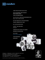
Collet Closer and Tailstock Options
GD5C2 and DD100 Pneumatic
Fail-Safe Collet Closers
• Spring-close, air-to-open for
fail-safe operation (85psi max)
• Part remains clamped even if
loss of air should occur
• Non-adjustable grip force
GD5C2 and DD100 Pneumatic
High-Force Collet Closers
• Dual cylinder for greater resulting force
• Set force according to levels below
the maximum allowed for the
workholding system
GD16C2, GD3J2, DD200 and
DD300 Pneumatic Collet Closers
• Dual cylinder
• Set force according to levels below
the maximum allowed for the
workholding system
• Accepts power chucks
GD5C2
pneumatic
fail-safe
collet closer
DD100
pneumatic
fail-safe
collet closer
GD5C2
pneumatic
high-force
collet closer 1
DD100
pneumatic
high-force
collet closer 1
GD16C2
and GD3J2
pneumatic
collet closer
DD200
& DD300
pneumatic
collet closer
GD160LP
pneumatic
collet closer
GD210LP
pneumatic
collet closer
GD5C2
manual
collet closer
for multi-spindle
5C2 units,
DD100, DD200
and DD300
GD160LP and GD210LP
Pneumatic Collet Closer
• Air open and air close actuation
• Enough stroke for power chuck use
GD5C2 Manual Collet Closer
• Manual lever open and close
Manual Drawbar
• Individual drawbar turns in by hand
for low-cost option
All collet closers have a through-hole to accommodate through coolant, while some can accommodate
long parts. Valving is included with pneumatic collet closers when purchased with indexer.
DRAWBAR FORCE
@70 PSI / 4.8 BAR
950 lb / 431 kg
THRU
HOLE
1.18" (30.00)
.125" (3.1)
Pneumatic Fail-Safe 2
1760 lb / 798 kg
1.08" (27.43)
.060" (1.5)
N/A
GD5C2
Pneumatic High Force
1950 lb / 885 kg
.311" (7.90)
.060" (1.5)
required
DD100
Pneumatic Fail-Safe 2
1760 lb / 798 kg
1.00" (25.40)
.060" (1.5)
N/A
DD100
Pneumatic High Force
1950 lb / 885 kg
.311" (7.90)
.060" (1.5)
required
GD16C2
Pneumatic
4560 lb / 2068 kg
1.62" (41.275)
.625" (15.8)
N/A
GD3J2
Pneumatic
4560 lb / 2068 kg
1.75" (44.450)
.625" (15.8)
N/A
GD160LP
Pneumatic
1825 lb / 828 kg
1.08" (27.432)
.375" (9.5)
N/A
GD210LP
Pneumtic
2792 lb / 1266 kg
1.625" (41.30)
.625" (15.8)
N/A
DD200
Pneumatic
2400 lb / 1088 kg
1.68" (42.80)
.625" (15.8)
N/A
DD300
Pneumatic
2400 lb / 1088 kg
1.68" (42.80)
.625" (15.8)
N/A
ROTARY
COLLET CLOSER
GD5C2
Manual (lever-operated)
GD5C2
Notes: 1– mounting plate required for using the rotary unit in a vertical on-end position
2 – 85 psi / 5.8 bar maximum drawbar force for fail-safe collet closers 20
MOUNTING
PLATE 1
N/A
STROKE
(millimeters in parentheses)
Manual Tailstock
for GD5C2 and DD100
.551 (14)
2.52
(64)
6.69
(170)
4±.001
(101.6±.025)
6.3
(160)
.51 (13)
2.24 (57)
Hardinge tailstocks are designed to be used where extra
support is needed for either workpiece or fixture holding.
Workpieces that have a length-to-diameter ratio of greater
than 3-to-1 are candidates for a tailstock support. This is
especially true when attempting to achieve high accuracy
levels. Choose from manually- or pneumatically-operated
tailstocks.
3.11
(79)
7.51
(191)
3±.0003
(76±.0076)
4
(101.6)
.433 (11)
1" Tailstock Riser included for GD160LP
1 (25.4)
9.13 (232)
7.69
(195.4)
5±.001
(127±.025)
to spindle
centerline
height w/riser
10 (254)
2" Tailstock Riser included for GD16C2, GD3J2, GD210LP, DD200
8.69
(220.7)
6±.001
(152.4±.025)
to spindle
centerline
height w/riser
2 (50.8)
9.13 (232)
10 (254)
3" Tailstock Riser included for DD300
9.69
(246.1)
7±.001
(177.8±.025)
to spindle
centerline
height w/riser
3 (76.2)
9.13 (232)
Manual Tailstock
• Manually-operated quill-type tailstock with convenient
hand wheel – 1/4-turn quill lock
• #3 Morse taper spindle
• Only live centers are recommended for use
• Base locating pins to reference and configure with any
Hardinge Rotary System
• Riser plate is supplied for all rotary devices with spindle
centerline above 4" (101.6)
10 (254)
Pneumatic Tailstock
for GD5C2 and DD100
.35 (9)
12.28 (312)
2.52 (64)
2.75 (70)
4±.001
(101.6±.025)
6.3
(160)
2.24 (57)
7.52
(191)
3±.0003
(76±.0076)
4
(101.6)
.275 (7)
.51 (13)
6.33 (161)
1" Tailstock Riser included for GD160LP
Pneumatic Tailstock
7.75
(196.8)
height w/riser
5±.001
(127±.025)
to spindle
centerline
10 (254)
2" Tailstock Riser included for GD16C2,GD3J2, GD210LP, DD200
8.75
(222.2)
height w/riser
9.13 (232)
2 (50.8)
6±.001
(152.4±.025)
to spindle
centerline
10 (254)
3" Tailstock Riser included for DD300
9.75
(247.6)
height w/riser
9.13 (232)
3 (76.2)
7±.001
(177.8±.025)
to spindle
centerline
10 (254)
(millimeters in parentheses)
21
www.shophardinge.com
• Allows greater level of cell automation and reduces
operator fatigue
• #3 Morse taper spindle
• Only live centers are recommended for use
• May be operated from a host CNC machine tool via
M-code or by the operation of a convenient hand valve
• Large actuator diameter produces higher forces than
competitor's brands
• Riser plate is supplied for all rotary devices with spindle
centerline above 4" (101.6)
• Pneumatic valving included
9.13 (232)
1 (25.4)
Plate and Cube Trunnion
Accessories
Imagine the possibilities for multiple part processing…
• low-profile clamping
• window box fixturing for 4-sided machining
• toggle and saddle clamping
• collet blocks
Standard Features
• Bearing pillow block assures rigid, accurate positioning
and will accommodate heavy loads
• Multiple part fixturing for increased output
• Load up a second plate to maximize cutting time
• All parts can be machined efficiently with the same tool
before going to the next tool
• Plates provide two sides for fixturing, while the cube
provides four sides
• 360° revolution depending on part clearance required
• Can be field installed to existing rotary units
• Plates are of blackened steel and the cube is of solid aluminum
for ease of drilling and slotting according to the application
requirements, either by Hardinge or by the customer
• One-inch pillow block riser included for use with
DD300 rotary table indexer
• Custom manufacturing available
Custom manufacturing available
Optional Features
ROTARY DEVICE
COMPATIBILITY
GD5C2
Centerline
Overall Length
DD100
Centerline
Overall Length
GD160LP
Centerline
Overall Length
GD16C2
Centerline
Overall Length
GD210LP
Centerline
Overall Length
DD200
Centerline
Overall Length
DD300
Centerline
Overall Length
(millimeters in parentheses)
22
PT5C
5C PLATE
YES
4" (101.6)
23.80" (607)
YES
4" (101.6)
28.82 (732)
YES
5" (127.0)
23.48 (596)
NO
NO
NO
NO
PTA25
A2-5 PLATE
CTA25
A2-5 CUBE
NO
NO
NO
NO
NO
NO
YES
6" (152.4)
37.54" (954)
YES
6" (152.4)
31.04" (788.3)
YES
6" (152.4)
37.68 (957)
YES
7" (177.8)
37.87 (962)
YES
6" (152.4)
37.48" (952)
YES
6" (152.4)
32.07" (814.7)
YES
6" (152.4)
37.63( 956)
YES
7" (177.8)
37.82 (961)
• Pillow block clamp available on PTA25 and CTA25
models with clamping torque of 275 ft-lb / 373 Nm
• Rotary union in pillow block for pneumatic fixturing on
the cube trunnion – part number CJ 0002483CTA
• Complete line of collet blocks available for gripping round,
hex, square and odd-shaped parts using collet sizes from
1C up to 35J
Collet Blocks
PT5C2 Tilting Plate Trunnion for GD5C2, GD160LP
and DD100 Rotary Units – Dimensions:
see chart
12 (305)
8 (203.2)
7 (178)
3.5 (89)
PT5C2
PTA25
CTA25-4IN
CTA25-6IN
1 (25.4)
4.92
(125)
4.92
(125)
End View
1" Riser
Required for
GD160LP
End View
10 (254)
1 (25.4)
Front View
3 (76.2)
1.29 (33)
15.86 (403)
.47 (12)
Plate positions
at offsets of:
0.00
0.25" (6.35)
1.50" (38.1)
1.75" (44.45)
4 (101.6)
3 (76.2)
Top View
Bottom View
PTA25 Tilting Plate Trunnion
for GD16C2, GD3J2, GD210LP, DD200
and DD300 Rotary Units
Dimensions:
Plate Trunnion PT5C2
see chart
• 4 x 10" (101.6 x 254)
machineable area on
two surfaces
• Adjustable centerline to
accommodate various
part heights
• Collet-style face plate draws in
to the 5C spindle nose of the
rotary product
• 1" riser* required for GD160LP
19.25 (489)
11.98
(304)
DD300*
1.25 (31.75)
5.51 (140)
16.73 (425)
Front View
1 (25.4)
9.48 (241)
End View
2.13 (54)
3
(76.2)
.98
(25)
Plate Trunnion PTA25
• 7 x 16.73" (177.8 x 425)
machineable area on
two surfaces
• Adjustable centerline to
accommodate various
part heights
• Face plate bolts on to the
A2-5 spindle nose of the
rotary product
• 1" riser* required for DD300
1 (25.4)
10.98
(279)
3
(76.2)
Bottom View
10
(254)
7
(177.8)
Top View
Plate positions
at offsets of:
0.00
0.50" (12.70)
0.75" (19.05)
2.00" (50.80)
2.25" (57.15)
2.75" (69.85)
3.00" (76.20)
CTA25-4IN and CTA25-6IN
Tilting Cube Trunnions
for GD16C2, GD3J2, GD210LP,
DD200 and DD300 Rotary Units
Dimensions:
see chart
Cube Trunnion CTA25
12.5
(317)
DD300*
Front View
4 (101.6) 4" CUBE
2 (50.8) 6" CUBE
9.5 (241)
End View
2.11 (54)
.98
(25)
4 (101.6)
6 (152.4)
Rotary
Union
Option
Cube positions
at a fixed
centerline
(2) 1/8" NPT
Bottom View
Top View
(millimeters in parentheses)
23
www.shophardinge.com
• 18" (457mm) long solid
aluminum block for four-sided
machining applications
• Available in 4" and 6" cubes
• 1/8" NPT ports to
accommodate air-actuated
workholding
• Face plate bolts on to the
A2-5 spindle nose of the
rotary product
• Can easily be configured for
highly productive 2D work
• 1" riser* required for DD300
18 (457)
11.5
(292)
Workholding Options
Hardened and
Ground Collets
Sure-Grip® Expanding
Collet Systems
• Manufactured to exacting standards
from special alloy steel
• Mount directly into the collet seat
of the spindle
• Threads are heat treated and body is
spring tempered to assure accuracy
and durability at low cost
• Solid, one-piece body and arbor
combination with a minimum of parts
required to expand the collet
• Wide range of standard sizes and
shapes (and some not so standard)
"off-the-shelf"
• Expanding arbor instantly locates on
center, unlike other designs
• Round, hex, rectangular, square and
emergency collets (ready to bore)
• 5C, 16C and 3J
• Quick collet changeover
• Wide gripping range for each collet
• True parallel gripping with a high
gripping force
• 5C, 16C and 3J
Step Chucks
• Accurately hold work up to, or larger
than, 6" (152.4) diameter
• Castings, moldings, stampings and
machined parts are held rigidly and
accurately
• Tubing can be held without crushing
or distortion
• Regular-Depth Step Chucks are 3⁄8"
larger in diameter than the rated size
so the full capacity may be readily
applied to a depth of 1⁄2"
• Extra-Depth Step Chucks are made so
the full rated capacity may be applied to
a depth of 11⁄4"
• Small closing angles available on step
chucks for non-rotating use • A step chuck closer is required for all
rotating spindle applications – mounts
directly on the spindle nose
24
16C-to-5C Spindle Adapter
Fixture Plates
• Mounts on A2-5 spindle rotary unit to
enable the use of standard 5C tooling
• Used to mount parts which cannot
be held with a collet or jaw chuck
• An inside taper corresponding to that
on the step chuck places the closing
pressure over the stepped area of the
chuck, resulting in greater gripping
power and accuracy
• Clamping method to be designed,
manufactured and balanced by
the customer
• Emergency Step Chucks are supplied
with pin holes and pins in place for
precision just-in-time machining
• Collet and spindle-mount styles
available
• 5C, 16C and 3J
Slotted Face Plates
• Precision ground in sizes
to fit all rotary units
Collets and Sure-Grip® Expanding Collets
Step Chucks and FlexC™ Collet Systems
Manual and Power Chucks
Face and Fixture Plates
FlexC™ Vulcanized Collet Systems
Sure-Grip® 3-Jaw Power Chucks
Manual Jaw Chucks
• A2-5 Spindle mount style
• Lever-operated, counter-centrifugal
and dynamically balanced to maintain
jaw force
• 5" / 6" 3-jaw and 4-jaw,
8" and 10" 3-jaw styles
• .0004" (.010mm) concentricity
• Round, hex, square and emergency styles
• ±.020 (.5mm) gripping range will
accommodate stock variation
• Testing indicates a mechanical
advantage over wedge-style chucks
• 1/4 to 29/16" 65mm capacity
• Accuracy and repeatability up to .0005"
(.0127mm) for 4" to 8" chucks
• 7/32 to 15/8" 42mm capacity
• 5C threaded-nose style
for GD5C2 indexer
• A2-5 spindle mount styles
• 3-Jaw universal and 4-jaw
independent draw
* Linkup and/or adapter required – please specify
indexer model at time of order.
* Linkup and/or adapter required – please specifiy indexer model.
** Riser Plate recommended
25
www.shophardinge.com
Product Descriptione
GD16C2
GD160LP
GD210LP
DD100
DD200
DD300
GD5C2
GD3J2
Spindle
A2-5 16C
A2-4
A2-5
A2-4 5C
A2-5
A2-5
5C threaded-nose
A2-5 3J
FlexC Collet System (Style D)
V65-5D00500*
V65-5D00500*
—
V65-5D00500*
—
V65-5D00500*
V65-5D00500*
—
4" Power Chuck
—
S CA-2000304-A24H
—
—
—
—
—
—
5" Power Chuck
SCA-2000305-A25H SCA-2200305-A25C*
—
SCA-2000305-A25H
—
SCA-2000305-A25H SCA-2000305-A25H
—
6" Power Chuck
SCA-2000306-A25H SCA-2300306-A25C*
—
SCA-2000306-A25H
—
SCA-2000306-A25H SCA-2000306-A25H
—
8" Power Chuck
SCA-2000308-A25H
—
SCA-2000308-A25H
—
SCA-2000308-A25H SCA-2000308-A25H
—
O/A
10" Power Chuck
O/A
—
O/A
—
O/A
O/A
—
O/A
5" 3-Jaw Universal Manual Chuck
53B-5405-HB D
—
—
—
—
—
—
—
5" 4-Jaw Independent Manual Chuck
54B-5405-HB D
—
—
—
—
—
—
—
6" 3-Jaw Universal Manual Chuck
63B-5405-HB D
—
63B-5405-BCA5
—
63B-5405-BCA5
63B-5405-BCA4
63B-5405-BCA5
63B-5405-BCA5
6" 4-Jaw Independent Manual Chuck
64B-5405-HB D
—
64B-5405-BCA5
—
64B-5405-BCA5
64B-5405-BCA4
64B-5405-BCA5
64B-5405-BCA5
8" 3-Jaw A2-5 Manual Chuck
83A-5405
83A-5405
—
83A-5405
—
83A-5405
83A-5405
—
10" 3-Jaw A2-5 Manual Chuck
13-5405
—
13-5405
—
13-5405
13-5405
—
13-5405
3" Spindle-mount Fixture Plate
—
—
—
—
—
—
53A-0008750-D
—
5" Spindle-mount Fixture Plate
—
—
—
—
—
—
55A-0008750-D
—
51/2" Spindle-mount Fixture Plate
A2-0008750-05
—
A2-0008750-05
—
A2-0008750-05
A2-0008750-05
—
A2-0008750-05
87/8" Spindle-mount Fixture Plate
A2-0008750-08
—
A2-0008750-08
—
A2-0008750-08
A2-0008750-08
—
A2-0008750-08
33⁄8" Collet-style Fixture Plate
—
1397-00-00
—
1397-00-00
—
—
1397-00-00
—
43⁄8" Collet Style Fixture Plate
—
1399-00-00
—
1399-00-00
—
—
1399-00-00
—
63⁄8" Collet-style Fixture Plate
1785-00-00
—
1785-00-00
—
1785-00-00
1785-00-00
—
—
210mm Slotted Face Plate (50mm thru)
—
—
—
CJ 1990200M
—
—
—
—
8.26" Slotted Face Plate (2" thru hole)
—
—
—
CJ 1990200E
—
—
—
—
170mm Slotted Face Plate (19mm thru)
—
—
—
RT 0007214A4
—
—
—
—
160mm Slotted Face Plate (25mm thru)
—
L1 0001990160M
—
—
—
—
—
—
6.229" Slotted Face Plate (1" thru hole)
—
L1 0001990160E
—
—
—
—
—
—
7" Slotted Face Plate (.437mm thru)
—
—
—
—
—
—
57A-0000692-D
—
87/8" Slotted Face Plate (.437mm thru)
A2 0000692-A9
—
A2 0000692-A9
—
A2 0000692-A9
A2 0000692-A9
—
A2 0000692-A9
10" Slotted Face Plate (1.5" thru hole)
CJ 000199020
—
CJ 000199020
—
CJ 000199020
CJ 000199020
—
CJ 000199020
12" Slotted Face Plate (2" thru hole)
RT 000690009**
—
RT 000690009**
—
RT 000690009**
RT 000690009
—
RT 000690009
Spindle Adapter 16C-to-5C
CJ 00002835CA
—
CJ 00002835CA
—
CJ 00002835CA
CJ 00002835CA
—
—
Manual Index and Inspection Fixtures
Manual index fixtures are used in both production and toolroom environments as a low cost, quick and
accurate means of holding a workpiece and performing indexing operations. The tapered or threaded-nose
spindles are hardened and ground. They accept all standard 5C collets, step chucks with closers, expanding
collets, Dead-Length® collets and manual jaw chucks.
Manual Indexer
Part Number
HV-4 A with Plain Spindle and 24-Hole Index Plate
HV-4N A with Threaded-Nose Spindle and 24-Hole Index Plate
HV-4NX A with Taper-Nose Spindle and 24-Hole Index Plate
H-4 B with 24-Hole Index Plate
HV-0000002-P4
HV-0000002-D4
HV-0000002-T4
HF-0000002-24
Index Plates
Part Number
Blank Index Plate for HV Models
20-Hole Index Plate for HV Models
24-Hole Index Plate for HV Models
Blank Index Plate for H-4 Model
20-Hole Index Plate for H-4 Model
24-Hole Index Plate for H-4 Model
HV-9004138
HV-0004138-2A
HV-0004138-4A
HF-9004138
HF-0004138-20
HF-0004138-24
Figure
page 27
1
1
1
2
Figure
page 27
3
4
5
6
7
8
A - Used in horizontal or vertical positions.
B - Used in horizontal position only.
Tailstocks and Inspection Fixtures
• The SB-4 Sub-Base with the tailstocks
can be used as a bench center
• The L-4 Tailstock has a hardened and ground spindle
which is lever-operated with a rack and pinion
- Spindle is spring loaded to hold the
center against the workpiece
- Position lock is provided
• The hardened and ground spindle on the T-4
Tailstock is screw fed and can be locked in any
position with a hexagon clamp bolt
- Removable keys permit the tailstocks
to be applied directly to any machine table
• SB-4 Sub-Base accepts various combinations
of fixtures such as the HV and H-4 series of
indexing fixtures
26
Tailstocks and Sub-Base
Part Number
Figure
L-4 Tailstock with Rapid Movement Lever
HV-0000056
9
T-4 Tailstock with Screw Adjustment
HF-0000056
10
SB-4 Sub-Base
HV-0001996-A
11
Figure 1
HV-4, HV-4N, HV-4NX
Dimensions:
HV-4
HV-4N
HV-4NX
H-4
Figure 2
H-4 Dimensions:
Manual Indexer
Standard Features
• Choice of spindle nose
- HV-4 plain
- HV-4N threaded nose
- HV-4NX taper nose
- H-4 24-hole index plate only
• Includes 24-hole index plate
• HV models can be used
horizontal or vertical
Optional Features
• Blank index plates
• 20-hole index plates
• 24-hole replacement index plates
Figures 3 - 8 Indexer Plate Configurations:
3
4
5
6
7
8
Figures 9
L-4 Dimensions:
Workholding Capacities
(threaded and taper nose indexers only)
Collets – Round (max. capacity)
11/16" (26.98)
29/32" (23.01)
Collets – Hex (max. capacity) 3/4" (19.05)
Collets – Square (max. capacity) Step Chucks – Regular Depth up to 6" (152.4)
Step Chucks – Extra Depth
up to 6" (152.4)
3-Jaw Chuck
5" (127)
3-Jaw Chuck
6" (152.4)
Sure-Grip® Expanding Collets 1/8" - 3" (3.17 - 76.2)
Fixture Plate – Spindle Mount 3" (76.2)
Fixture Plate – Spindle Mount 5" (127)
Fixture Plate – Collet Style 33/8" (85.72)
Fixture Plate – Collet Style 43/8" (111.12)
Slotted Face Plate (diameter)
7" (178)
Collet Stops for part positioning
YES
Figures 10
T-4 Dimensions:
Figures 11
SB-4 Dimensions:
27
www.shophardinge.com
(millimeters in parentheses)
SPINDLE TOOLING FOR MANUAL AND CNC LATHES
COLLETS FOR AUTOMATICS, TURRET LATHES AND
ROTARY TRANSFER MACHINES
TOOLING FOR GRINDING MACHINES
SWISS-TYPE COLLETS, GUIDE BUSHINGS AND BARLOADER COLLETS
FLEXC™ COLLET SYSTEMS FOR LATHES
HQC® QUICK-CHANGE COLLET SYSTEMS FOR AUTOMATICS
SURE-GRIP® EXPANDING COLLET SYSTEMS
HCAC® COLLET ADAPTATION CHUCKS
SURE-GRIP® 3-JAW POWER CHUCKS
CHUCK JAWS
TOOLHOLDER COLLETS, BUSHINGS & TOOL HOLDERS
PRECISION CNC TOOLING FOR MILLS
COLLET BLOCKS
ROTARY TABLES AND INDEXERS
CUSTOM WORKHOLDING
MACHINE TOOLS
Hardinge Inc. One Hardinge Drive | P.O. Box 1507 | Elmira, New York 14902-1507 USA
USA: 800-843-8801 | Canada: 800-468-5946 | Fax: 607-734-3886
To Order Online: www.shophardinge.com | Corporate Homepage: www.hardinge.com
E-mail: [email protected] | Live Online Support: www.shophardinge.com
All specifications are subject to change without notice due to ongoing continuous improvement. All marks indicated
by ® and ™ are trademarks of Hardinge Inc. Brochure #2372J • Litho in USA • ©Hardinge Inc. 2012 • 2M Nov 2011
Cert no. BV-COC-054711