1
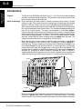
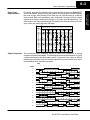
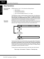
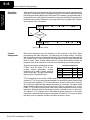
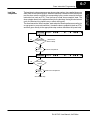
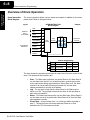
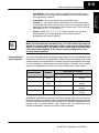
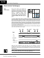
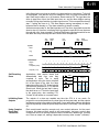
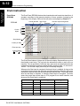
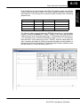
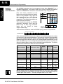
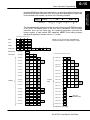
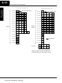
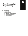
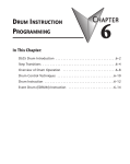
Drum Instruction
Programming
In This Chapter. . . .
— Introduction
— Step Transitions
— Overview of Drum Operation
— Drum Control Techniques
— Drum Instruction
16
6--2
Drum Instruction Programming
Drum Instruction
Programming
Introduction
Purpose
Drum Terminology
The Event Drum (EDRUM) instruction in the F1--130 CPU electronically simulates
an electro-mechanical drum sequencer. The instruction offers enhancements to the
basic principle, which we describe first.
Drum instructions are best suited for repetitive processes that consist of a finite
number of steps. They can do the work of many rungs of ladder logic with elegant
simplicity. Therefore, drums can save a lot of programming and debugging time.
We introduce some terminology associated with the drum instruction by describing
the original mechanical drum shown below. The mechanical drum generally has
pegs on its curved surface. The pegs are populated in a particular pattern,
representing a set of desired actions for machine control. A motor or solenoid rotates
the drum a precise amount at specific times. During rotation, stationary wipers sense
the presence of pegs (present = on, absent = off). This interaction makes or breaks
electrical contact with the wipers, creating electrical outputs from the drum. The
outputs are wired to devices on a machine for On/Off control.
Drums usually have a finite number of positions within one rotation, called steps.
Each step represents some process step. At powerup, the drum resets to a
particular step. The drum rotates from one step to the next based on a timer, or on
some external event. During special conditions, a machine operator can manually
increment the drum step using a jog control on the drum’s drive mechanism. The
contact closure of each wiper generates a unique on/off pattern called a sequence,
designed for controlling a specific machine. Because the drum is circular, it
automatically repeats the sequence once per rotation. Applications vary greatly, and
a particular drum may rotate once per second, or as slowly as once per week.
Pegs
Wipers
Drum
Outputs
Electronic drums provide the benefits of mechanical drums and more. For example,
they have a preset feature that is impossible for mechanical drums: The preset
function lets you move from the present step directly to any other step on command!
DL105 PLC User Manual, 3rd Edition
6--3
Drum Instruction Programming
For editing purposes, the electronic drum is presented in chart form in DirectSOFT
and in this manual. Imagine slicing the surface of a hollow drum cylinder between
two rows of pegs, then pressing it flat. Now you can view the drum as a chart as
shown below. Each row represents a step, numbered 1 through 16. Each column
represents an output, numbered 0 through 15 (to match word bit numbering). The
solid circles in the chart represent pegs (On state) in the mechanical drum, and the
open circles are empty peg sites (Off state).
OUTPUTS
STEP 15 14 13 12 11 10 9 8 7 6 5 4 3 2 1 0
1
f F f F f f F f f f F f f F f f
2
f F f F F f F f f f f F f f F f
3
f F F F F f F F f f f f f f f f
4
F F f F F f F f F f f f f f f F
5
f f f F f f F f F f F f F f f F
6
f f f F f f F f F f F f F F f F
7
F f f F f f F F F F f F F F f F
8
F f F f f F f F F f f f F f f F
9
f f f f f f f F F f f f F f f f
10
f f f f f f f F F F f f f f f f
11
F f f f F f f f f F f f f f F f
12
f F f f F F f f F f F F f F F f
13
f f F f f f f f f f f F F f F f
14
f f f f f f f F f f f F F f F F
15
F f f f f F f F f F f F f f F F
16
f f F f f f f F f F f F F f f F
Output Sequences The mechanical drum sequencer derives its name from sequences of control
changes on its electrical outputs. The following figure shows the sequence of On/Off
controls generated by the drum pattern above. Compare the two, and you will find
that they are equivalent! If you can see their equivalence, you are well on your way to
understanding drum instruction operation.
Step
Output
0
1
2
3
4
5
6
7
8
9
10
11
12
13
14
15
1
2
3
4
5
6
7
8
9
10
11
12
13
14
15
16
1
0
1
0
1
0
1
0
1
0
1
0
1
0
1
0
1
0
1
0
1
0
1
0
1
0
1
0
1
0
1
0
DL105 PLC User Manual, 3rd Edition
Drum Instruction
Programming
Drum Chart
Representation
6--4
Drum Instruction Programming
Drum Instruction
Programming
Step Transitions
Drum Instruction
Parameters
Timer-Only
Transitions
EDRUM operation in the F1--130 includes the following features:
S Up to 16 steps
S Time-based step transitions
S Event-based step transitions
S Up to 16 discrete outputs per drum (X, Y, or C type)
The EDRUM has 16 steps, and each step has 16 outputs. Refer to the figure below.
Each output can be either an X, Y, or C coil, offering a lot of programming flexibility.
We assign Step 1 an arbitrary unique output pattern (f= Off, F= On) as shown.
When programming the EDRUM instruction, you also determine both the output
assignment and the On/Off state (pattern) at that time. All steps use the same output
assignment, but each step may have its own unique output pattern.
Drums move from one step to another based on time and/or an external event
(input). Each step has its own transition condition which you assign during the drum
instruction entry. The figure below shows how timer-only transitions work.
Step 1
Outputs:
F f f f F f F f f f f F F f f f
Outputs:
f f f F f f f f F F f F f f F F
Increment
count timer
No
Has counts per
step expired?
Yes
Step 2
Use next transition criteria
The drum stays in Step 1 for a specific duration (user-programmable). The timebase
of the timer is programmable, from 0.01 seconds to 99.99 seconds. This establishes
the resolution, or the duration of each “tick of the clock”. Each step uses the same
timebase, but has its own unique counts per step, which you program. When the
counts for Step 1 have expired, then the drum moves to Step 2. The outputs change
immediately to match the new pattern for Step 2.
The drum spends a specific amount of time in each step, given by the formula:
Time in step = 0.01 seconds X Timebase x Counts per step
DL105 PLC User Manual, 3rd Edition
Drum Instruction Programming
6--5
NOTE: When first choosing the timebase resolution, a good rule of thumb is to make
it about 1/10 the duration of the shortest step in your drum. Then you will be able to
optimize the duration of that step in 10% increments. Other steps with longer
durations allow optimizing by even smaller increments (percentage-wise). Also,
note that the drum instruction executes once per CPU scan. Therefore, it is pointless
to specify a drum timebase that is much faster than the CPU scan time.
Timer and Event
Transitions
Step transitions may also occur based on time and/or external events. The figure
below shows how step transitions work in these cases.
Step 1
No
Outputs:
F f f f F f F f f f f F F f f f
Is Step event
true?
Yes
Increment
count timer
No
Has step
counts expired?
Yes
Step 2
Outputs:
f f f F f f f f F F f F f f F F
Use next transition criteria
When the drum enters Step 1, it sets the output pattern as shown. Then it begins
polling the external input programmed for that step. You can define event inputs as
X, Y, or C discrete point types. Suppose we select X0 for the Step 1 event input. If X0
is off, then the drum remains in Step 1. When X0 is On, the event criteria is met and
the timer increments. The timer increments as long as the event (X0) remains true.
When the counts for Step 1 have expired, then the drum moves to Step 2. The
outputs change immediately to match the new pattern for Step 2.
DL105 PLC User Manual, 3rd Edition
Drum Instruction
Programming
For example, if you program a 5 second time base and 12 counts for Step 1, then the
drum will spend 60 seconds in Step 1. The maximum time for any step is given by the
formula:
Max Time per step = 0.01 seconds X 9999 X 9999
= 999,800 seconds = 277.7 hours = 11.6 days
Drum Instruction
Programming
6--6
Drum Instruction Programming
Event-Only
Transitions
Step transitions do not require both the event and the timer criteria programmed for
each step. You have the option of programming just one of the two, and even mixing
transition types among all the steps of the drum. For example, you might want Step 1
to transition on an event, Step 2 to transition on time only, and Step 3 to transition on
both time and an event. Furthermore, you may elect to use only part of the 16 steps,
and only part of the 16 outputs.
Step 1
No
Outputs:
F f f f F f F f f f f F F f f f
Outputs:
f f f F f f f f F F f F f f F F
Is Step event
true?
Yes
Step 2
Use next transition criteria
Counter
Assignments
Each drum instruction uses the resources of four counters in the CPU. When
programming the drum instruction, you select the first counter number. The drum
also uses the next three counters automatically. The counter bit associated with the
first counter turns on when the drum has completed its cycle, going off when the
drum is reset. These counter values and the counter bit precisely indicate the
progress of the drum instruction, and can be monitored by your ladder program.
Suppose we program a timer drum to have
8 steps, and we select CT10 for the
counter number (remember, counter
numbering is in octal). Counter usage is
shown to the right. The right column holds
typical values, interpreted below.
Counter Assignments
CT10 Counts in step V1010
1528
CT11 Timer Value
V1011
0200
CT12 Preset Step
V1012
0001
CT13 Current Step
V1013
0004
CT10 shows that we are at the 1528th count in the current step, which is step 4
(shown in CT13). If we have programmed step 4 to have 3000 counts, then the step
is just over half completed. CT11 is the count timer, shown in units of 0.01 seconds.
So, each least-significant-digit change represents 0.01 seconds. The value of 200
means that we have been in the current count (1528) for 2 seconds (0.01 x 100).
Finally, CT12 holds the preset step value which was programmed into the drum
instruction. When the drum’s Reset input is active, it presets to step 1 in this case.
The value of CT12 changes only if the ladder program writes to it, or the drum
instruction is edited and the program is restarted. Counter bit CT10 turns on when
the drum cycle is complete, and turns off when the drum is reset.
DL105 PLC User Manual, 3rd Edition
Drum Instruction Programming
The last step in a drum sequence may be any step number, since partial drums are
valid. Refer to the following figure. When the transition conditions of the last step are
met, the drum sets the counter bit corresponding to the counter named in the drum
instruction box (such as CT0). Then it moves to a final “drum complete” state. The
drum outputs remain in the pattern defined for the last step. Having finished a drum
cycle, the Start and Jog inputs have no effect at this point.
The drum leaves the “drum complete” state when the Reset input becomes active (or
on a program-to--run mode transition). It resets the drum complete bit (such as CT0),
and then goes directly to the appropriate step number defined as the preset step.
Last step
No
Outputs:
Are transition
conditions met?
F F F f f f F f f F f F F F f F
(Timer and/or
Event criteria)
Yes
Set
CT0 = 1
Set Drum Complete bit
Complete
No
Outputs:
F F F f f f F f f F f F F F f F
Reset Input
Active?
Yes
Reset
CT0 = 0
Reset Drum Complete bit
Go to Preset Step
DL105 PLC User Manual, 3rd Edition
Drum Instruction
Programming
Last Step
Completion
6--7
6--8
Drum Instruction Programming
Drum Instruction
Programming
Overview of Drum Operation
Drum Instruction
Block Diagram
The drum instruction utilizes various inputs and outputs in addition to the drum
pattern itself. Refer to the figure below.
Inputs
DRUM INSTRUCTION
Block Diagram
Outputs
Start
Realtime
Inputs
(from ladder)
Jog
Reset
Drum
Preset Step
Counts/Step
Programming
Selections
Timebase
Step
Control
Step
Pointer
Events
f
f
f
F
f
f
f
f
f
f
f
F
F
F
F
F
F
f
f
f
F
F
f
F
f
f
f
F
f
f
f
f
f f
f f
F f
F f
F f
F F
F F
f F
Final Drum
Outputs
Counter #
Pattern
Counter Assignments
CT0
Counts in step
V1000
xxxx
CT1
Timer Value
V1001
xxxx
CT2
Preset Step
V1002
xxxx
CT3
Current Step
V1003
xxxx
The drum instruction accepts several inputs for step control, the main control of the
drum. The inputs and their functions are:
S
S
S
S
Start -- The Start input is effective only when Reset is off. When Start is
on, the drum timer runs if it is in a timed transition, and the drum looks
for the input event during event transitions. When Start is off, the drum
freezes in its current state (Reset must remain off), and the drum
outputs maintain their current on/off pattern.
Jog -- The jog input is only effective when Reset is off (Start may be
either on or off). The jog input increments the drum to the next step on
each off-to-on transition.
Reset -- The Reset input has priority over the Start input. When Reset is
on, the drum moves to its preset step. When Reset is off, then the Start
input operates normally.
Preset Step -- A step number from 1 to 16 that you define (typically is
step 1). The drum moves to this step whenever Reset is on, and
whenever the CPU first enters run mode.
DL105 PLC User Manual, 3rd Edition
Drum Instruction Programming
S
S
Counts/Step -- The number of timer counts the drum spends in each
step. Each step has its own counts parameter. However, programming
the counts/step is optional.
Timer Value -- the current value of the counts/step timer.
Counter # -- The counter number specifies the first of four consecutive
counters which the drum uses for step control. You can monitor these to
determine the drum’s progress through its control cycle. The DL105 has
64 counters (CT0 -- CT77 in octal).
Events -- Either an X, Y, C, S, T, or CT type discrete point serves as
step transition inputs. Each step has its own event. However,
programming the event is optional.
WARNING: The outputs of a drum are enabled any time the CPU is in Run
Mode. The Start Input does not have to be on, and the Reset input does not
disable the outputs. Upon entering Run Mode, drum outputs automatically
turn on or off according to the pattern of the current step of the drum. This
initial step number depends on the counter memory configuration: non-retentive versus retentive.
Powerup State of
Drum Registers
The choice of the starting step on powerup and program-to-run mode transitions are
important to consider for your application. Please refer to the following chart. If the
counter memory is configured as non-retentive, the drum is initialized the same way
on every powerup or program-to-run mode transition. However, if the counter
memory is configured to be retentive, the drum will stay in its previous state.
Counter Number
Function
CT(n)
Initialization on Powerup
Non-Retentive Case
Retentive Case
Current Step
Count
Initialize = 0
Use Previous (no
change)
CT(n + 1)
Counter Timer
Value
Initialize = 0
Use Previous (no
change)
CT(n + 2)
Preset Step
Initialize = Preset Step #
Use Previous (no
change)
CT(n + 3)
Current Step #
Initialize = Preset Step #
Use Previous (no
change)
Applications with relatively fast drum cycle times typically will need to be reset on
powerup, using the non-retentive option. Applications with relatively long drum cycle
times may need to resume at the previous point where operations stopped, using the
retentive case. The default option is the retentive case. This means that if you
initialize scratchpad V--memory, the memory will be retentive.
DL105 PLC User Manual, 3rd Edition
Drum Instruction
Programming
S
S
6--9
6--10
Drum Instruction Programming
Drum Instruction
Programming
Drum Control Techniques
Drum
Control Inputs
Now we are ready to put together the
concepts on the previous pages and
demonstrate general control of the drum
instruction box. The drawing to the right
shows a simplified generic drum
instruction. Inputs from ladder logic
control the Start, Jog, and Reset Inputs.
The first counter bit of the drum (CT0, for
example) indicates the drum cycle is
done.
X0
Start
X1
Jog
X2
Reset
Setup
Info.
Steps
Outputs
f
f
f
F
f
f
f
f
f
f
f
F
F
F
F
F
F
f
f
f
F
F
f
F
f
f
f
F
f
f
f
f
f f
f f
F f
F f
F f
F F
F F
f F
The timing diagram below shows an arbitrary timer drum input sequence and how
the drum responds. As the CPU enters Run mode it initializes the step number to the
preset step number (typically it is Step 1). When the Start input turns on the drum
begins running, waiting for an event and/or running the timer (depends on the setup).
After the drum enters Step 2, Reset turns On while Start is still On. Since Reset has
priority over Start, the drum goes to the preset step (Step 1). Note that the drum is
held in the preset step during Reset, and that step does not run (respond to events or
run the timer) until Reset turns off.
After the drum has entered step 3, the Start input goes off momentarily, halting the
drum’s timer until Start turns on again.
Start
drum
Inputs
Start
1
0
Jog
1
0
Reset
1
0
Reset
drum
Hold
drum
Resume
drum
Drum
Reset
Complete drum
Drum Status
1
Step #
Drum
Complete (CT0)
1
Outputs (x 16)
1
0
1
2
1
1
2
3
3
4
...
15
16
16
16
1
1
0
When the drum completes the last step (Step 16 in this example), the Drum
Complete bit (CT0) turns on, and the step number remains at 16. When the Reset
input turns on, it turns off the Drum Complete bit (CT0), and forces the drum to enter
the preset step.
NOTE: The timing diagram shows all steps using equal time durations. Step times
can vary greatly, depending on the counts/step programmed.
DL105 PLC User Manual, 3rd Edition
6--11
Drum Instruction Programming
Jog
drum
Inputs
Start
1
0
Jog
1
0
Reset
1
0
Reset
drum
Jog
drum
Jog
drum
Drum
Complete
Drum Status
1
Step #
Self-Resetting
Drum
Initializing Drum
Outputs
Using Complex
Event Step
Transitions
Drum
Complete (CT0)
1
Outputs (x 16)
1
0
2
3
3
3
4
5
6,7
8
...
14
15
16
16
16
1
0
Applications often require drums that
automatically start over once they
complete a cycle. This is easily
accomplished, using the drum complete
bit. In the figure to the right, the drum
instruction setup is for CT0, so we logically
OR the drum complete bit (CT0) with the
Reset input. When the last step is done,
the drum turns on CT0 which resets itself
to the preset step, also resetting CT0.
Contact X2 still works as a manual reset.
X0
Start
X1
Start
Setup
Info.
X2
Reset
Steps
CT0
Outputs
f
f
f
F
f
f
f
f
f
f
f
F
F
F
F
F
F
f
f
f
F
F
f
F
f
f
f
F
f
f
f
f
f f
f f
F f
F f
F f
F F
F F
f F
The outputs of a drum are enabled any time the CPU is in run mode. On
program-to-run mode transitions, the drum goes to the preset step, and the outputs
energize according to the pattern of that step. If your application requires all outputs
to be off at powerup, make the preset step in the drum a “reset step”, with all outputs
off.
Each event-based transition accepts only one contact reference for the event.
However, this does not limit events to just one contact. Just use a control relay
contact such as C0 for the step transition event. Elsewhere in ladder logic, you may
use C0 as an output coil, making it dependent on many other “events” (contacts).
DL105 PLC User Manual, 3rd Edition
Drum Instruction
Programming
In the figure below, we focus on how the Jog input works on event drums. To the left
of the diagram, note that the off-to-on transitions of the Jog input increments the
step. Start may be either on or off (however, Reset must be off). Two jogs takes the
drum to step three. Next, the Start input turns on, and the drum begins running
normally. During step 6 another Jog input signal occurs. This increments the drum to
step 7, setting the timer to 0. The drum begins running immediately in step 7,
because Start is already on. The drum advances to step 8 normally.
As the drum enters step 14, the Start input turns off. Two more Jog signals moves the
drum to step 16. However, note that a third Jog signal is required to move the drum
through step 16 to “drum complete”. Finally, a Reset input signal arrives which forces
the drum into the preset step and turns off the drum complete bit.
6--12
Drum Instruction Programming
Drum Instruction
Programming
Drum Instruction
Event Drum
(EDRUM)
The Event Drum (EDRUM) features time-based and event-based step transitions. It
operates according to the general principles of drum operation covered in the
beginning of this chapter. Below is the instruction as displayed by DirectSOFT.
Counter Number Step Preset
EDRUM2
Timebase
Discrete Output Assignment
Start
Control
Inputs
Jog
Reset
Step Number
Counts per Step
Event per step
Output Pattern
= Off,
= On
The Event Drum features 16 steps and 16 discrete outputs. Step transitions occur on
timed and/or event basis. The jog input also advances the step on each off-to-on
transition. Time is specified in counts per step, and events are specified as discrete
contacts. Unused steps must be programmed with “counts per step” = 0, and event =
“K0000”. The discrete output points may be individually assigned.
Whenever the Start input is energized, the drum’s timer is enabled. As long as the
event is true for the current step, the timer runs during that step. When the step count
equals the counts per step, the drum transitions to the next step. This process stops
when the last step is complete, or when the Reset input is energized. The drum
enters the preset step chosen upon a CPU program-to-run mode transition, and
whenever the Reset input is energized.
Drum Parameters
Field
Data Types
Ranges
Counter Number
aa
--
0 -- 74
Preset Step
bb
K
1 -- 16
Timer base
cccc
K
0.01 -- 99.99 seconds
Counts per step
dddd
K
0 -- 9999
Event
eeee
X, Y, C, S, T, CT
see page 4--29
Discrete Outputs
ffff
X, Y, C
see page 4--29
DL105 PLC User Manual, 3rd Edition
Drum Instruction Programming
6--13
Counter Number
Ranges of (n)
Function
Counter Bit Function
CT(n)
0 -- 74
Counts in step
CTn = Drum Complete
C( n+1)
1 -- 75
Timer value
CT(n+1) = (not used)
CT( n+2)
2 --76
Preset Step
CT(n+2) = (not used)
CT( n+3)
3 --77
Current Step
CT(n+1) = (not used)
The following ladder program shows the EDRUM instruction in a typical ladder
program, as shown by DirectSOFT. Steps 1 through 11 are used, and all sixteen
output points are used. The preset step is step 1. The timebase runs at (K100 x 0.01)
= 0.1 second per count. Therefore, the duration of step 1 is (5 x 0.1) = 0.5 seconds.
Note that step 1 is time-based only (event = “K0000”). And, the output pattern for
step 1 programs all outputs off, which is a typically desirable powerup condition. In
the last rung, the Drum Complete bit (CT4) turns on output Y0 upon completion of the
last step (step 10). A drum reset also resets CT4.
DL105 PLC User Manual, 3rd Edition
Drum Instruction
Programming
Drum instructions use four counters in the CPU. The ladder program can read the
counter values for the drum’s status. The ladder program may write a new preset
step number to CT(n+2) at any time. However, the other counters are for monitoring
purposes only.
Drum Instruction
Programming
6--14
Drum Instruction Programming
Handheld
Programer
Drum Mnemonics
The EDRUM instruction may be programmed using either DirectSOFT or a
handheld programmer. This section covers entry via the handheld programmer
(Refer to the DirectSOFT manual for drum instruction entry using that tool).
First, enter Store instructions for the
ladder rungs controlling the drum’s ladder
inputs. In the example to the right, the
timer drum’s Start, Jog, and Reset inputs
are controlled by X0, X1 and X2
respectively. The required keystrokes are
listed beside the mnemonic.
These keystrokes precede the EDRUM
instruction mnemonic. Note that the
ladder rungs for Start, Jog, and Reset
inputs are not limited to being
single--contact rungs.
X0
Start
X1
Jog
Setup
Info.
Reset
Steps
X2
Outputs
Mask
f
f
f
F
f
f
f
f
f
f
f
F
F
F
F
F
F
f
f
f
F
F
f
F
f
f
f
F
f
f
f
f
f f
f f
F f
F f
F f
F F
F F
f F
Handheld Programmer Keystrokes
$
Store X0
A
STR
0
ENT
(Repeat for Store X1 and Store X2)
After the Store instructions, enter the EDRUM (using Counter CT0) as shown:
Handheld Programmer Keystrokes
EDRUM CNT0
SHFT
E
4
D
3
R
ORN
U
ISG
M
ORST
A
0
ENT
After entering the EDRUM mnemonic as above, the handheld programmer creates
an input form for all the drum parameters. The input form consists of approximately
fifty or more default mnemonic entries containing DEF (define) statements. The
default mnemonics are already “input” for you, so they appear automatically. Use the
NXT and PREV keys to move forward and backward through the form. Only the
editing of default values is required, thus eliminating many keystrokes. The entries
required for the basic timer drum are in the chart below.
Drum Parameters
Multiple Entries
Mnemonic / Entry
Default
Mnemonic
Valid Data
Types
Ranges
Start Input
--
STR (plus input rung)
--
--
--
Jog Input
--
STR (plus input rung)
--
--
--
Reset Input
--
STR (plus input rung)
--
--
Drum Mnemonic
--
DRUM CNT aa
--
K
0 -- 74
Preset Step
1
bb
DEF K0000
K
1 -- 16
Timer base
1
cccc
DEF K0000
K
2 -- 9999
Output points
16
ffff
DEF 0000
X, Y, C *
see page
4--29
Counts per step
16
dddd
DEF K0000
K
0 -- 9999
Events
16
dddd
DEF K0000
X, Y, C, S,
T, CT
see page
4--29
Output pattern
16
gggg
DEF K0000
K
0 -- FFFF
NOTE: Default entries for output points and events are “DEF 0000”, which means
they are unassigned. If you need to go back and change an assigned output as
unused again, enter “K0000”. The entry will again show as “DEF 0000”.
DL105 PLC User Manual, 3rd Edition
6--15
Drum Instruction Programming
Step 1
Outputs:
-- converts to:
f f f f F f f F f f f F F f F f
15
0
9
1
0
A
The following diagram shows the method for entering the previous EDRUM example
on the HHP. The default entries of the form are in parenthesis. After the drum
instruction entry (on the fourth row), the remaining keystrokes over-write the
numeric portion of each default DEF statement. NOTE: Drum editing requires
Handheld Programmer firmware version 1.7 or later.
Handheld Programmer Keystrokes
Start
$
Jog
$
Reset
$
Drum Inst.
SHFT
A
STR
B
STR
C
STR
E
4
D
NOTE: You may use the NXT and PREV keys
to skip past entries for unused outputs or steps.
ENT
0
ENT
1
ENT
2
R
ORN
3
U
Preset Step
( DEF K0001)
NEXT
Time Base
( DEF K0000 )
G
( DEF 0000 )
SHFT
C
( DEF 0000 )
SHFT
C
( DEF 0000 )
SHFT
Y
MLS
B
( DEF 0000 )
SHFT
Y
MLS
E
( DEF 0000 )
SHFT
Y
MLS
F
( DEF 0000 )
SHFT
Y
MLS
G
( DEF 0000 )
SHFT
C
E
( DEF 0000 )
SHFT
C
( DEF 0000 )
SHFT
Y
MLS
A
( DEF 0000 )
SHFT
Y
MLS
C
( DEF 0000 )
SHFT
C
B
( DEF 0000 )
SHFT
C
( DEF 0000 )
SHFT
Y
MLS
G
( DEF 0000 )
SHFT
Y
MLS
H
( DEF 0000 )
SHFT
C
D
16 ( DEF 0000 )
SHFT
Y
MLS
1
6
Outputs
E
4
2
2
2
2
2
2
2
M
ORST
ISG
A
0
ENT
Handheld Programmer Keystrokes cont’d
NEXT
H
B
C
D
B
7
1
1
4
5
6
4
2
0
2
1
3
6
7
3
1
NEXT
A
0
NEXT
1 ( DEF K0000 )
F
( DEF K0000 )
C
NEXT
( DEF K0000 )
NEXT
( DEF K0000 )
NEXT
( DEF K0000 )
NEXT
( DEF K0000 )
NEXT
( DEF K0000 )
NEXT
Counts/
Step
( DEF K0000 )
B
E
B
J
B
I
5
2
1
4
1
9
1
8
( DEF K0000 )
B
( DEF K0000 )
E
NEXT
( DEF K0000 )
NEXT
NEXT
( DEF K0000 )
NEXT
NEXT
( DEF K0000 )
NEXT
NEXT
( DEF K0000 )
NEXT
( DEF K0000 )
NEXT
16 ( DEF K0000 )
NEXT
NEXT
NEXT
E
A
E
4
0
4
NEXT
NEXT
1
4
NEXT
A
F
F
I
C
C
G
C
A
0
5
5
8
2
2
6
2
0
NEXT
A
NEXT
0
NEXT
A
D
A
E
A
A
0
3
0
4
0
0
NEXT
NEXT
NEXT
NEXT
A
0
NEXT
NEXT
skip over
unused steps
(Continued on next page)
DL105 PLC User Manual, 3rd Edition
Drum Instruction
Programming
Using the DRUM entry chart (two pages before), we show the method of entry for the
basic time/event drum instruction. First, we convert the output pattern for each step
to the equivalent hex number, as shown in the following example.
6--16
Drum Instruction Programming
Drum Instruction
Programming
Handheld Programmer Keystrokes cont’d
1
( DEF 0000 )
( DEF 0000 )
( DEF 0000 )
( DEF 0000 )
( DEF 0000 )
( DEF 0000 )
( DEF 0000 )
( DEF 0000 )
SHFT
SHFT
SHFT
SHFT
SHFT
SHFT
Events
( DEF 0000 )
( DEF 0000 )
( DEF 0000 )
16
skip over unused event
NEXT
SHFT
SHFT
SHFT
SHFT
( DEF 0000 )
NEXT
( DEF 0000 )
NEXT
( DEF 0000 )
NEXT
( DEF 0000 )
NEXT
( DEF 0000 )
NEXT
Handheld Programmer Keystrokes cont’d
Y
MLS
E
X
SET
B
X
SET
C
C
A
C
2
2
B
X
SET
A
X
SET
F
X
SET
D
Y
MLS
H
C
C
2
4
1
2
0
1
0
5
3
7
2
1
NEXT
( DEF K0000 )
NEXT
( DEF K0000 )
NEXT
( DEF K0000 )
NEXT
NEXT
NEXT
NEXT
Output
Pattern
NEXT
0
NEXT
Last rung
C
E
( DEF K0000 )
J
( DEF K0000 )
E
( DEF K0000 )
J
( DEF K0000 )
16
J
F
( DEF K0000 )
step 1 pattern = 0000
NEXT
( DEF K0000 )
( DEF K0000 )
NEXT
A
( DEF K0000 )
D
F
I
9
2
4
5
9
4
9
3
5
8
I
I
E
B
D
E
E
I
I
E
( DEF K0000 )
NEXT
( DEF K0000 )
NEXT
( DEF K0000 )
NEXT
( DEF K0000 )
NEXT
( DEF K0000 )
NEXT
$
GY
CNT
A
Y
MLS
A
STR
SHFT
8
8
4
1
3
4
4
8
8
4
B
J
H
G
E
I
F
1
9
7
6
4
8
5
C
E
G
J
D
G
J
SHFT
A
G
E
E
6
4
H
2
4
6
9
3
6
9
0
4
7
NEXT
NEXT
NEXT
NEXT
NEXT
NEXT
NEXT
NEXT
NEXT
unused steps
0
0
NEXT
NEXT
NOTE: You may use the NXT and PREV keys
to skip past entries for unused outputs or steps.
DL105 PLC User Manual, 3rd Edition
NEXT