1
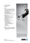
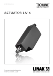
CONNECTION DIAGRAM - LA14
English
Deutsch
Italiano
CONNECTION DIAGRAM - LA14
LA14 ACTUATOR
Actuator with Parallel
14XXXXXXXX003X1X=XX1XXXXXXXXZX
Actuator 8
Actuator 7
Actuator 6
Actuator 5
Actuator 4
Actuator 3
Actuator 2
BROWN
Communication
Communication
IN
OUT
Communication
IN
OUT
Communication
IN
OUT
INWARDS
12/24V DC
BLUE
Communication
H-Bridge
Communication
IN
OUT
IN
OUT
M
H-Bridge
Communication
IN
OUT
INWARDS
OUTWARDS
VIOLET
WHITE
INWARDS
M
Communication
INWARDS
M
OUTWARDS
H-Bridge
IN
OUT
INWARDS
M
OUTWARDS
H-Bridge
IN
OUT
YELLOW*
GREEN*
INWARDS
M
OUTWARDS
H-Bridge
INWARDS
M
OUTWARDS
H-Bridge
M
OUTWARDS
H-Bridge
INWARDS
BLACK
M
OUTWARDS
H-Bridge
OUTWARDS
RED
Please be aware that if the power supply is not properly connected,
you might damage the actuator!
For more information on how to install this
product please see the LA14 User Manual
Page 1
Copyright© LINAK . 2015.11 . MA-M9-02-597 . LINAK A/S reserves the right to make technical alterations
Actuator 1
CONNECTION DIAGRAM - LA14
LA14 ACTUATOR
Actuator with Parallel
14XXXXXXXX003X1X=XX1XXXXXXXXZX
Blue
Specification
12-24VDC + (VCC)
Connect Brown to
positive
12V ± 20%
24V ± 10%
12-24VDC - (GND)
Connect Blue to
negative
Comments
Note: Do not change the power
supply polarity on the brown and
blue wires!
The parallel actuators can run on one
OR separate power supplies
Power supply GND (-) is electrically
connected to the housing
Current limit levels can be adjusted
through BusLink (only one actuator
at a time for parallel)
Red
12V ± 20%
24V ± 10%
Extends the actuator
Black
Retracts the actuator
Green
Endstop signal out
Yellow
Endstop signal in
Violet
Parallel communication:
Violet cords must be connected together
Signal GND:
White cords must be connected together
The green and yellow wires from parallel connected actuators
must NOT be interconnected.
White
*
For more information on how to install this
product please see the LA14 User Manual
Page 2
Copyright© LINAK . 2015.11 . MA-M9-02-597 . LINAK A/S reserves the right to make technical alterations
Input/
Output
Brown
ANSCHLUSSDIAGRAMM - LA14
LINEARANTRIEB LA14
Parallelantrieb
14XXXXXXXX003X1X=XX1XXXXXXXXZX
Antrieb 8
Antrieb 7
Antrieb 6
Antrieb 5
Antrieb 4
Antrieb 3
Antrieb 2
BRAUN
Communication
Communication
IN
OUT
Communication
IN
OUT
Communication
IN
OUT
INWARDS
12/24V DC
BLAU
Communication
H-Bridge
Communication
IN
OUT
IN
OUT
M
H-Bridge
Communication
IN
OUT
INWARDS
OUTWARDS
VIOLETT
WEIß
INWARDS
M
Communication
INWARDS
M
OUTWARDS
H-Bridge
IN
OUT
INWARDS
M
OUTWARDS
H-Bridge
IN
OUT
GELB*
GRÜN*
INWARDS
M
OUTWARDS
H-Bridge
INWARDS
M
OUTWARDS
H-Bridge
M
OUTWARDS
H-Bridge
INWARDS
SCHWARZ
M
OUTWARDS
H-Bridge
OUTWARDS
ROT
Bitte beachten Sie, dass wenn der Stromanschluss nicht korrekt
verbunden ist, der Aktuator beschädigt werden kann!
Weitere Informationen zur Installation dieses Produkts finden Sie in der LA14 Montageanleitung
Seite 1
Copyright© LINAK . 2015.11 . MA-M9-02-597 . LINAK A/S reserves the right to make technical alterations
Antrieb 1
ANSCHLUSSDIAGRAMM - LA14
LINEARANTRIEB LA14
Parallelantrieb
14XXXXXXXX003X1X=XX1XXXXXXXXZX
Braun
Blau
Spezifikation
Kommentare
12-24 V DC + (VCC)
Braun an Pluspol
anschließen
Hinweis: Verändern Sie nicht die
Stromversorgungspolarität der
braunen und blauen Drähte.
12V ±20 %
24V ±10 %
Die Parallelantrieb können über
eine ODER mehrere getrennt
Stromversorgung/-en betrieben
werden.
12-24 V DC - (GND)
Blau an Minuspol
anschließen
Stromversorgung GND (-) ist elektrisch mit dem Gehäuse verbunden.
Rot
Schwarz
Grün
12V ±20 %
24V ±10 %
Fährt den Antrieb aus
Fährt den Antrieb ein
Endstopp-Signalausgang ausgefahren
Gelb
Endstopp-Signalausgang eingefahren
Violett
Parallelkommunikation:
Violette Kabel müssen miteinander verbunden werden.
Signal-GND:
Weiße Kabel müssen miteinander verbunden werden
Die grünen und gelben Drähte von parallel angeschlossenen
Antriebe dürfen NICHT miteinander verbunden werden.
Weiß
*
Weitere Informationen zur Installation dieses Produkts finden Sie in der LA14 Montageanleitung
Seite 2
Copyright© LINAK . 2015.11 . MA-M9-02-597 . LINAK A/S reserves the right to make technical alterations
Eingang/
Ausgang
SCHEMA DI COLLEGAMENTO - LA14
ATTUATORE LINEARE 14
Attuatore con opzione Parallelo
14XXXXXXXX003X1X=XX1XXXXXXXXZX
Attuatore 8
Attuatore 7
Attuatore 6
Attuatore 5
Attuatore 4
Attuatore 3
Attuatore 2
MARRONE
Communication
12/24V DC
Communication
IN
OUT
Communication
IN
OUT
Communication
IN
OUT
INWARDS
BLU
Communication
H-Bridge
IN
OUT
IN
OUT
M
H-Bridge
VIOLA
Communication
IN
OUT
INWARDS
OUTWARDS
Communication
BLANCO
INWARDS
M
Communication
INWARDS
M
OUTWARDS
H-Bridge
IN
OUT
INWARDS
M
OUTWARDS
H-Bridge
IN
OUT
GIALLO*
VERDE*
INWARDS
M
OUTWARDS
H-Bridge
INWARDS
M
OUTWARDS
H-Bridge
M
OUTWARDS
H-Bridge
INWARDS
NERO
M
OUTWARDS
H-Bridge
OUTWARDS
ROSSO
Si prega di prestare attenzione ai collegamenti. Se l’attuatore non è
alimentato correttamente, potrebbe danneggiarsi!
Per maggiori informazioni su come installare questo prodotto si prega di consultare
LA14 User Manual
Pagina 1
Copyright© LINAK . 2015.11 . MA-M9-02-597 . LINAK A/S reserves the right to make technical alterations
Attuatore 1
SCHEMA DI COLLEGAMENTO - LA14
ATTUATORE LINEARE 14
Attuatore con opzione Parallelo
14XXXXXXXX003X1X=XX1XXXXXXXXZX
Input/
Output
Specifica
Commenti
Blu
12V ± 20%
24V ± 10%
12-24VDC - (GND)
Connettere il blu al
negativo
Gli attuatori possono funzionare
in parallelo sia con un’unica
alimentazione che alimentazioni
separate
Alimentazione GND (-) è connessa elettricamente alla carcassa
Rosso
Nero
Verde
12V ± 20%
24V ± 10%
Fuoriuscita attuatore
Retrarre l’attuatore
Segnale fine corsa out
Giallo
Segnale fine corsa in
Viola
Comunicazione parallelismo:
I fili viola devono essere collegati insieme
Segnale GND:
I fili bianchi devono essere collegati insieme
I fili verde e giallo di attuatori collegati in parallelo NON
possono essere interconnessi.
Bianco
*
Per maggiori informazioni su come installare questo prodotto si prega di consultare
LA14 User Manual
Pagina 2
Copyright© LINAK . 2015.11 . MA-M9-02-597 . LINAK A/S reserves the right to make technical alterations
Marrone 12-24VDC + (VCC)
Nota: Non modificare la polarità
Connettere il marrone dell’alimentazione sui fili maral positivo
rone e blu!