1
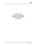
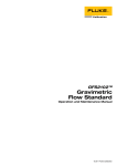
MPG1™
Manual Pressure Generator/Controller
for Hydraulic Pressure
Operation and Maintenance Manual
© 2004-2007 DH Instruments, a Fluke Company
High pressure liquids and gases are potentially hazardous. Energy stored in these liquids and gases
can be released unexpectedly and with extreme force. High pressure systems should be assembled and
operated only by personnel who have been instructed in proper safety practices.
© 2004-2007 DH Instruments, a Fluke Company All rights reserved.
Information in this document is subject to change without notice. No part of this document may be reproduced or
transmitted in any form or by any means, electronic or mechanical, for any purpose, without the express written
permission of DH Instruments, a Fluke Company, 4765 East Beautiful Lane Phoenix AZ 85044-5318 USA.
DH Instruments makes sincere efforts to ensure the accuracy and quality of its’ published materials; however,
no warranty, expressed or implied, is provided. DH Instruments disclaims any responsibility or liability for any direct
or indirect damages resulting from the use of the information in this manual or products described in it. Mention of
any product or brand does not constitute an endorsement by DH Instruments of that product or brand. This manual
was originally composed in English and was subsequently translated into other languages. The fidelity of the
translation cannot be guaranteed. In case of conflict between the English version and other language versions, the
English version predominates.
DH Instruments, DH, DHI, MPG1, OPG1, GPC1, PG7000, RPM4 are trademarks, registered and otherwise, of
DH Instruments, a Fluke Company.
Document No. 550134a
070405
Printed in the USA
© 2004-2007 DH Instruments, a Fluke Company
TABLE OF CONTENTS
TABLE OF CONTENTS
TABLE OF CONTENTS ............................................................... I
TABLES ..................................................................................II
FIGURES.................................................................................II
ABOUT THIS MANUAL ............................................................. III
1.
2.
3.
INTRODUCTION ................................................................. 1
1.1
PRODUCT OVERVIEW ...........................................................................................................................1
1.2
SPECIFICATIONS ...................................................................................................................................1
1.3
LOCATION OF THE COMPONENTS ......................................................................................................2
1.4
DIMENSIONAL SCHEMATICS................................................................................................................3
1.5
SYSTEM SCHEMATIC ............................................................................................................................4
INSTALLATION .................................................................. 5
2.1
UNPACKING AND INSPECTION ............................................................................................................5
2.2
SITE REQUIREMENTS............................................................................................................................5
2.3
INITIAL SETUP ........................................................................................................................................6
OPERATION ....................................................................... 7
3.1
GENERAL OPERATING PRINCIPLES AND INFORMATION.................................................................7
3.1.1
3.1.2
3.1.3
3.1.4
3.2
OPERATION ............................................................................................................................................8
3.2.1
3.2.2
3.2.3
4.
FILLING AND PRIMING THE SYSTEM UNDER TEST.................................................................................8
GENERATING AND ADJUSTING PRESSURE.............................................................................................8
REFILLING OR EMPTYING THE VARIABLE VOLUME WITHOUT RELEASING TEST PRESSURE ........9
MAINTENANCE AND ADJUSTMENTS .................................. 11
4.1
5.
OVERVIEW ....................................................................................................................................................7
VALVES .........................................................................................................................................................7
VARIABLE VOLUME (VV).............................................................................................................................7
RESERVOIR ..................................................................................................................................................8
REPLACING LIQUID AND FLUSHING HYDRAULIC SYSTEM............................................................11
WARRANTY STATEMENT .................................................. 13
Page I
© 2004-2007 DH Instruments, a Fluke Company
MPG1 USER’S MANUAL
TABLES
Table 1. MPG1 Parts List ............................................................................................................................. 5
Table 2. DHI Authorized Service Providers ............................................................................................... 14
FI G U R E S
Figure 1.
Figure 2.
Figure 3.
Figure 4.
Figure 5.
Front View..................................................................................................................................... 2
Rear View ..................................................................................................................................... 2
Front View with Dimensions ......................................................................................................... 3
Bottom and Side Views with Dimensions ..................................................................................... 3
System Schematic ........................................................................................................................ 4
© 2004-2007 DH Instruments, a Fluke Company
Page II
ABOUT THIS MANUAL
ABOUT THIS MANUAL
This manual provides the user with the information necessary to operate an MPG1 Manual Pressure
Generator/Controller. It also includes additional information provided to help you optimize MPG1 use and
take full advantage of its many features and functions.
For those of you who “don’t read manuals”, go directly to section 2.3 to set up your MPG1. Then go to
section 3.2. This will get you running quickly with minimal risk of causing damage to yourself or your MPG1.
Then… when you have questions or start to wonder about all the great features you might be missing, get into
the manual!
Manual Conventions
(CAUTION) is used throughout the manual to identify user warnings and cautions.
(NOTE) is used throughout the manual to identify operating and applications advice and
additional explanations.
Page III
© 2004-2007 DH Instruments, a Fluke Company
MPG1 USER’S MANUAL
NO T E S
© 2004-2007 DH Instruments, a Fluke Company
Page IV
1. INTRODUCTION
1.
INTRODUCTION
1.1
PRODUCT OVERVIEW
The DHI Manual Pressure Generator/Controller for hydraulic pressure (MPG1) provides a
compact and easy to use system for manually generating, setting and finely adjusting
pressures between atmosphere and 200 MPa (30 000 psi) in closed volumes. MPG1 is a
standard pressure generation and control component for working with DHI PG7302 piston
gauges or liquid operated RPM4 reference pressure monitors.
1.2
SPECIFICATIONS
Pressure Range:
Variable Volume
Displacement:
Variable Volume Stroke
Reservoir Capacity
Pressure Connections:
Operating fluid
Dimensions:
MPG1-200M: Atmosphere to 200 MPa (30 000 psi)
3
MPG1-200M: 11 cc (0.7 in )
15.2 cm (6 in.)
3
362 cc (22.1 in )
DH 500 (DH500 is a gland and collar type fitting for ¼ in. (6 mm) coned and left
hand threaded tube. DH500 is equivalent to AE F250C, HIP HF4, etc.)
Any non-corrosive oil, water, water/alcohol. Inquire about other fluids
260 mm x 144 mm x 410 mm (WxHxD)
(10.2 in. x 5.7 in. x 16.1 in.) (see Section 1.4)
Variable volume handle span: 457 mm (18 in.)
Weight:
20 kg (44 lbs.)
Due to a policy of continual product improvement all specifications are subject to change without notice.
Page 1
© 2004-2007 DH Instruments, a Fluke Company
MPG1 USER’S MANUAL
1.3
LOCATION OF THE COMPONENTS
1.
2.
3.
4.
5.
6.
TEST2 Connection (DH500)
Reservoir isolation valve
TEST1 Connection (DH500)
Reservoir Cover
Test isolation valve
Variable volume
Figure 1. Front View
1.
2.
3.
4.
5.
6.
Reservoir
Test isolation valve
TEST1 Connection (DH500)
Reservoir isolation valve
TEST2 Connection (DH500)
Variable volume
Figure 2. Rear View
© 2004-2007 DH Instruments, a Fluke Company
Page 2
1. INTRODUCTION
1.4
DIMENSIONAL SCHEMATICS
All dimensions are in millimeter [mm]
Figure 3. Front View with Dimensions
Figure 4. Bottom and Side Views with Dimensions
Page 3
© 2004-2007 DH Instruments, a Fluke Company
MPG1 USER’S MANUAL
1.5
SYSTEM SCHEMATIC
4. TEST1 connection
5. TEST ISOLATION valve
6. Variable volume
1. RESERVOIR ISOLATION valve
2. Reservoir
3. TEST2 connection
Figure 5. System Schematic
© 2004-2007 DH Instruments, a Fluke Company
Page 4
2. INSTALLATION
2.
INSTALLATION
2.1
UNPACKING AND INSPECTION
MPG1 is delivered, along with its standard accessories, in a corrugated container held in place by
expandable foam.
The MPG1 is delivered with its valves closed and the variable volume (VV) fully screwed in.
reservoir and the MPG1 plumbing are free of fluid.
The
Remove MPG1 and its accessories from the shipping container and remove each item from its protective bag.
Check that all items are present and have no visible signs of damage.
Table 1. MPG1 Parts List
DESCRIPTION
MPG1-200M instrument
PART #
402122
Accessories including:
2.2
1 ea. Plug, DH500
100285
1 Operation and Maintenance Manual
550134
SITE REQUIREMENTS
There are two main site requirements for installing the MPG1:
•
MPG1 should be installed on a stable surface to which the MPG1 housing can be anchored using the
mounting holes in the bottom of the housing. This is to hold the MPG1 firmly in place when turning
the variable volume, particularly at high pressures and to avoid applying the torque from variable
volume rotation to the tubing and fittings which may be connected to the MPG1.
•
As the variable volume handles are wider than the MPG1 housing, the MPG1 needs to be mounted so
that the handles hang over the edge of the mounting surface, for example over the front of a work
bench.
Page 5
© 2004-2007 DH Instruments, a Fluke Company
MPG1 USER’S MANUAL
2.3
INITIAL SETUP
High pressure fluids are potentially hazardous. Energy stored in pressurized fluids can be released
unexpectedly and with extreme force. High pressure systems should be assembled and operated only by
personnel who have been instructed in proper safety practices.
To set up the MPG1 for operation, proceed as follows:
Anchor the MPG1 to a stable working surface using the mounting holes on the bottom of the MPG1
platform. The mounting hole diameter is 6.6 mm (0.26 in.) suitable for M6 or 1/4 in. screws. If
mounting to a wood bench top, use of threaded inserts and machine screws is recommended.
Connect the TEST1 and/or TEST2 port to the system into which pressure is to be generated and
controlled. All MPG1 pressure connections are DH500 female (DH500 is a gland and collar type
fitting for 1/4 in. (6 mm) coned and left hand threaded tube. DH500 is equivalent to AE F250C, HIP
HF4, etc.). If a TEST port is not being used, plug it using a DH500 plug supplied in the MPG1
accessories.
ALWAYS use external tubing and fittings rated for pressures equal to or greater than the maximum
pressure which MPG1 will be used to generate.
DH500 F fittings are delivered with disposable, orange, plastic dummy plugs installed. These are NOT
intended to hold high pressure. They should be removed and replaced with appropriate fittings or stainless
steel plugs before high pressure operation. Each dummy plug carries a DH500 collar. Remove and retain the
collar for use in connecting to the mating tube.
Fill the fluid reservoir: Close the RESERVOIR ISOLATION valve. Remove the reservoir cover by
lifting it off gently. Pour the desired fluid into the reservoir. Do not overfill. MPG1 is tested with a low
viscosity, fluorinated liquid and should be free of significant fluid residue as delivered.
Prime and leak check pressurized system (see Section 3.2).
© 2004-2007 DH Instruments, a Fluke Company
Page 6
3. OPERATION
3.
OPERATION
3.1
GENERAL OPERATING PRINCIPLES AND INFORMATION
3.1.1
OVERVIEW
See Section 1.5, Figure 5.
MPG1 is used to manually generate and adjust liquid pressure from atmosphere to 100 MPa
(15 000 psi) or 200 MPa (30 000 psi) using two valves and a variable volume. Fittings for
connecting to a device or system under test are located on the top and rear left side of the
instrument housing. A reservoir holds a supply of fluid.
3.1.2
VALVES
The RESERVOIR ISOLATION and TEST ISOLATION valves are manually operated needle valves.
The RESERVOIR ISOLATION valve isolates the reservoir from the pressurized circuit. It is
opened to fill the variable volume with fluid and to open the pressurized circuit to atmosphere
(vent).
The TEST ISOLATION valve isolates the TEST1 and TEST2 ports from the rest of the MPG1
circuit. It can be used to isolate the variable volume and reservoir from the pressurized test
system, for example, if it becomes necessary to refill the variable volume with fluid when it
reaches end of stroke. As the valve needle displaces fluid when it is operated, it can also be
used as a very fine variable volume for very fine pressure adjustment.
3.1.3
VARIABLE VOLUME (VV)
The variable volume (VV) is a piston-cylinder type screw press. Rotating the variable volume
handle, moves the piston in or out decreasing or increasing the volume and therefore
increasing or decreasing pressure.
The VV is used to generate and adjust pressure in the system to which MPG1 is connected
when the TEST ISOLATION valve is open. The torque necessary to rotate the VV handle is
proportional to the pressure in the variable volume.
Generally, the starting position of the VV when beginning to generate pressure from
atmosphere is with the piston fully retracted (handles rotated maximum CCW) so that the full
stroke of the VV is available to fill the test system and generate pressure.
During operation, if the VV runs out of stroke, the TEST ISOLATION and RESERVOIR
ISOLATION valves can be used in sequence to allow the variable volume to be refilled
without releasing the pressure on the TEST1 and TEST2 port (see Section 3.2.3).
The maximum operating pressure of the variable volume is 200 MPa (30 000 psi) in
MPG1-200M. Do not generate pressure greater than the maximum operating pressure.
Page 7
© 2004-2007 DH Instruments, a Fluke Company
MPG1 USER’S MANUAL
3.1.4
RESERVOIR
3
The reservoir is a 362 cc (22.1 in ) acrylic vessel mounted inside the MPG1 housing. It is
accessed for filling or cleaning by a friction fit lid through the top of the housing. The reservoir
is connected to the RESERVOIR ISOLATION valve by flexible tubing. The reservoir lid can
used to force fluid out of the reservoir into the system connected to the OPG1.
3.2
OPERATION
Operation of the MPG1 can be divided into three common tasks: filling and priming the system under test
(See Section 3.2.1); generating and adjusting pressure (see Section 3.2.2); filling or emptying the variable
volume while maintaining test system pressure (see Section 3.2.3).
3.2.1
FILLING AND PRIMING THE SYSTEM UNDER TEST
Before attempting to use the MGP1 to generate high pressure, the system to which it is
connected should be as free of air as possible. Minimizing the air in the pressurized system
increases the effectiveness of the variable volume in generating pressure.
When the MPG1 is first connected to a system to be pressurized or if a new device is
connected to the system, proceed as follows to fill and prime the system before attempting to
generate high pressure:
Connect the MPG1 to the system under test or connect a new device to the system. If
possible, leave an open connection or cracked fitting at a high point in the system to be
pressurized.
Open the RESERVOIR ISOLATION valve and close the TEST ISOLATION valve.
Fill the variable volume with fluid from the reservoir by screwing it all the way out (CCW)
to its end of stroke.
Close the RESERVOIR ISOLATION VALVE and open the TEST ISOLATION valve.
Screw in the variable volume (CW) while observing the open point in the test system.
When air free liquid comes out of the open point, close the open point. If the variable
volume is screwed all the way in before the system is filled, repeat steps through as
many times as necessary.
3
The displacement of the variable volume of the MPG1-200M is 11 cc (0.7 in ).
Proceed to generate and adjust pressure as desired (see Section 3.2.1).
The reservoir cover may be used to rapidly displace a large volume of fluid from the reservoir
into the test system connected to the TEST ports(s). With the RESERVOIR ISOLATION valve
closed, remove the reservoir cover. Open RESERVOIR ISOLATION and TEST ISOLATION valves.
Then, while holding a finger over the vent hole in the cover, slowly push the cover into position on
the reservoir. The cover acts as a “piston”, pushing fluid out of the reservoir into the system.
3.2.2
GENERATING AND ADJUSTING PRESSURE
Before attempting to use the MGP1 to generate high pressure, the system to which it is
connected should be as free of air as possible. See Section 3.2.1 to fill and prime the test system.
Once the system to which MPG1 is connected, filled and primed, to generate and adjust
pressure proceed as follows:
© 2004-2007 DH Instruments, a Fluke Company
Page 8
3. OPERATION
Open the RESERVOIR ISOLATION valve, close the TEST ISOLATION valve and back
the variable volume all the way out (CCW). This fills the variable volume with fluid and
makes the full stroke available to generate pressure.
Close the RESERVOIR ISOLATION valve, open the TEST ISOLATION valve. Use the
variable volume to increase, decrease and adjust pressure as desired. Note that the
TEST ISOLATION needle valve can be used as a mini variable volume for micro
pressure adjustment if desired. However, closing the TEST ISOLATION valve complete
isolates the test circuit from the main variable volume and the RESERVOIR ISOLATION
valve.
If the variable volume runs out of stroke when increasing or decreasing pressure, it can
be refilled without releasing pressure from the test system. See Section 3.2.3 for
instructions.
To release pressure from the test system and return pressure to atmosphere, use the
variable volume to reduce pressure as desired. For a rapid release to atmosphere and
full vent, open the RESERVOIR ISOLATION VALVE. Note that pressure will drop very
quickly when the RESERVOIR ISOLATION valve is opened. For a gentle pressure
decrease, always use the variable volume.
3.2.3
REFILLING OR EMPTYING THE VARIABLE VOLUME
WITHOUT RELEASING TEST PRESSURE
When working high pressure ranges with large test volumes or test volumes that are not fully
purged of air, the volume displaced by a single stroke of the variable volume may not be
sufficient to generate the maximum pressure desired. Conversely, when lowering pressure
the variable volume may run out of stroke before it is desirable to use the RESERVOIR
ISOLATION valve to release pressure rapidly. In these cases, the variable volume can be
backed off and refilled without releasing the pressure in the test system.
To refill or empty the variable volume without releasing test pressure, proceed as follows:
Close the TEST ISOLATION valve. This isolates the test system connected to the TEST
ports from the variable volume and the RESERVOIR ISOLATION valve. Note that after
refilling the variable volume, the TEST ISOLATION valve will be opened again. At that
time, the pressure on both sides of the valve will not be perfectly equal so the pressure in
the system connected to the TEST port(s) will change. Consider this possibility before
closing the TEST ISOLATION valve. For example, if using a piston gauge, put the piston
gauge piston at its bottom stop before closing the TEST ISOLATION valve.
Open the RESERVOIR ISOLATION valve.
volume and connects it to the reservoir.
This vents the pressure in the variable
Back out the variable volume (CCW) to fill it or screw it in (CW) to empty it, as desired.
Close the RESERVOIR ISOLATION VALVE. DO NOT OPEN THE TEST ISOLATION
VALVE YET.
Operate the variable volume as needed to generate a pressure equal to the pressure in
the system connected to the TEST port(s). This is the pressure that was present on the
variable volume before the TEST ISOLATION VALVE was closed in . The pressure
may be reasonably approximated by the feel (torque) on the variable volume.
Slowly open the TEST ISOLATION valve to equalize the pressure. Proceed to generate
and adjust pressure as desired (see Section 3.2.2).
Page 9
© 2004-2007 DH Instruments, a Fluke Company
MPG1 USER’S MANUAL
NO T E S
© 2004-2007 DH Instruments, a Fluke Company
Page 10
4. MAINTENANCE AND ADJUSTMENTS
4.
MAINTENANCE
AND ADJUSTMENTS
MPG1 was designed for maintenance free operation. The only recommended regular maintenance is to
flush the hydraulic system and replace the operating liquid.
4.1
REPLACING LIQUID AND FLUSHING HYDRAULIC SYSTEM
Regular replacement of MPG1’s operating liquid and flushing of the hydraulic system is recommended.
To empty the reservoir, remove the reservoir cover and siphon the bulk of liquid out of the reservoir.
Remove the balance of liquid from the system by cycling the variable volume with the TEST1 port
plugged and TEST2 port open following the filling and priming procedure described in Section 3.2.1.
Collect the used liquid as it comes out of the TEST1 port.
Refill the reservoir with fresh liquid. Pressurize MPG1 by plugging the TEST1 and TEST2 ports, closing
the RESERVOIR ISOLATION valve, opening the TEST ISOLATION valve and using the variable volume
to generate pressure. Then crack the TEST1 fitting to let fluid out. Screw the variable volume all the way
in to empty the variable volume out of the TEST1 port. Repeat until the liquid coming out of the TEST1
port is clean.
Page 11
© 2004-2007 DH Instruments, a Fluke Company
MPG1 USER’S MANUAL
NO T E S
© 2004-2007 DH Instruments, a Fluke Company
Page 12
5. WARRANTY STATEMENT
5.
WARRANTY STATEMENT
Except to the extent limited or otherwise provided herein, DH Instruments, a Fluke Company (DHI)
warrants for one year from purchase, each new product sold by it or one of its authorized distributors,
only against defects in workmanship and/or materials under normal service and use. Products which
have been changed or altered in any manner from their original design, or which are improperly or
defectively installed, serviced or used are not covered by this warranty.
DHI and any of its Authorized Service Providers’ obligations with respect to this warranty are limited to
the repair or replacement of defective products after their inspection and verification of such defects. All
products to be considered for repair or replacement are to be returned to DHI, or its Authorized Service
Provider, freight prepaid, after receiving authorization from DHI or its Authorized Service Provider. The
buyer assumes all liability vis-à-vis third parties in respect of its acts or omissions involving use of the
products. In no event shall DHI be liable to purchaser for any unforeseeable or indirect damage, it being
expressly stated that, for the purpose of this warranty, such indirect damage includes, but is not limited to,
loss of production, profits, revenue, or goodwill, even if DHI has been advised of the possibility thereof,
and regardless of whether such products are used individually or as components in other products.
Items returned to DHI under warranty claim but determined to not have a defect covered under warranty
or to not have a defect at all are subject to an evaluation and shipping charge as well as applicable repair
and/or calibration costs.
The provisions of this warranty and limitation may not be modified in any respect except in writing signed
by a duly authorized officer of DHI.
The above warranty and the obligations and liability of DHI and its authorized service providers exclude
any other warranties or liabilities of any kind.
Page 13
© 2004-2007 DH Instruments, a Fluke Company
MPG1 USER’S MANUAL
Table 2. DHI Authorized Service Providers
DH INSTRUMENTS, A FLUKE COMPANY
WWW.DHINSTRUMENTS.COM
AUTHORIZED SERVICE PROVIDERS
COMPANY
TELEPHONE
& FAX
ADDRESS
EMAIL
DH Instruments, a Fluke
Company
4765 East Beautiful Lane
Phoenix AZ 85044-5318
USA
Tel 602.431.9100
Fax 602.431.9559
[email protected]
Ohte Giken, Inc.
Technology Center
258-1 Nakadai Nihari-Gun
Ibaraki 300-0133
JAPAN
Tel 0298-55-8778
Fax 0298-55-8700
[email protected]
DHI Products Technical
Service Division
National Institute of Metrology
Heat Division
Pressure & Vacuum Lab
NO. 18, Bei San Huan Donglu
Beijing 100013
PR China
Tel 010-64291994 ext 5
Tel 010-64218637 ext 5
Fax 010-64218703
[email protected]
Minerva Meettechniek B.V.
Chrysantstraat 1
3812 WX Amersfoort
the NETHERLANDS
Tel (+31) 33.46.22.000
Fax (+31) 33.46.22.218
[email protected]
© 2004-2007 DH Instruments, a Fluke Company
Page 14