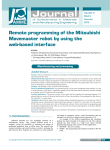
1
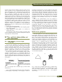
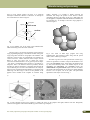
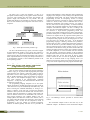
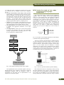
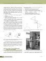
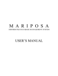
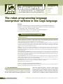
VOLUME 45
ISSUE 2
of Achievements in Materials
and Manufacturing Engineering
April
2011
The robot programming language
interpreter written in the Logo language
K. Foit*
Institute of Engineering Processes Automation and Integrated Manufacturing
Systems, Faculty of Mechanical Engineering, Silesian University of Technology,
ul. Konarskiego 18a, 44-100 Gliwice, Poland
* Corresponding author: E-mail address: [email protected]
Received 14.02.2011; published in revised form 01.04.2011
Manufacturing and processing
Abstract
Purpose: of this paper is to elaborate a simple system used to visualize the trajectory of the robot manipulator,
using the interpreter written in the Logo programming language. The interpreter should be able to run on the
older PC class hardware with limited RAM and CPU computing power.
Design/methodology/approach: Compared to the other programming languages, the Logo is a convenient
tool for use in the field of robotics, due to simple syntax, derived from LISP, direct support for mapping the
manipulator path on the computer graphics device (turtle graphics), and because the original application of turtle
graphics was an interface for mobile robot control.
Findings: As the subject of further consideration, the Mitsubishi RV-M1 robot has been selected. Its
programming language, called Movemaster Commands, is very simply and in some aspects very similar to
regular BASIC programming language. This makes it useful for processing by the interpreter due to imperative
programming model.
Research limitations/implications: The current, experimental version of the interpreter lacks some functions
(for example workspace limits checking). Another disadvantage is that the application is dedicated to the
particular type of robot. Some problems may also occur during the graphical user interface design, because this
part is not well implemented in the Logo.
Practical implications: The result of the experiment is the computer application. The program is written in the
FMSLogo programming language. The developed application shares the interface with the FMSLogo. This is
mainly due the fact, that the Logo is the interpreted language.
Originality/value: The program allows performing a simple check of the trajectory, and complements the
typical program editor. There is no need to use dedicated, high-price simulators.
Keywords: Robotics; Simulation; Logo
Reference to this paper should be given in the following way:
K. Foit, The robot programming language interpreter written in the Logo language, Journal of Achievements in
Materials and Manufacturing Engineering 45/2 (2011) 194-203.
1.
Introduction
1. Introduction
Robot programming is often done in high-level programming
language designed specifically for a particular type of robot. For
the same reason dedicated simulation applications are created,
194
Research paper
which allow testing the program - again for a specific type of
robot or a group of robots [1-10]. There are also complex
simulation systems, such as RobCAD, which have a large base of
robots possible to handle in a virtual environment, but their main
disadvantage is the high price and fairy complex usage. However,
in most cases, it is required to perform a simple check of the
© Copyright by International OCSCO World Press. All rights reserved. 2011
Manufacturing and processing
program, carried with the validation of trajectory points. In some
cases, an operator can use an application that will export each
point of the trajectory to the CAD program and will present the
path in an intelligible form [3,5]. However this method fails if the
path is created in a dynamic way, based on the result of
conditional statements in the program. In this case, you can try to
examine all the alternative trajectories, but this would require
sophisticated tool for source code analysis and developing the
form of path presentation in the CAD application. Another way of
solving this problem may be the translation of the robot program
to a description similar to the pseudo code, which could be
interpreted in a certain graphical environment. In this case, it was
decided to adapt the Logo language for the presentation of
manipulator’s trajectory. Compared to the other programming
languages, the Logo is a convenient tool for use in the field of
robotics, due to:
x simple syntax, derived from LISP,
x direct support for mapping the path on the computer graphics
device (turtle graphics),
x original application of turtle graphics is an interface for
mobile robot control.
In the next part of this work the concept of a simple system
used to visualize the trajectory of the robot manipulator, using the
Logo interpreter, will be presented.
2.The
overall
description
2. The overall
description
of the of
the
approach
approach
2.1.The history of the Logo
language
2.1. The
history of the Logo language
The first Logo interpreter was created in 1967 at BBN
laboratory, driven by three scientists: Bolt, Beranek and Newman,
located in Cambridge, Massachusetts. The creators were Wally
Feurzeig and Seymour Papert. Two years later, at Massachusetts
Institute of Technology, a turtle robot was created, as a Papert’s
initiative. Original idea of turtle robot was designed under
auspices of Wiliam Grey Walter in the late forties of XX century.
In later years Apple and Texas Instruments began a broad
campaign to promote Logo as a programming language for
beginners, especially useful for kids in primary schools. In this
way, this language has gained a reputation as trivial software for
children. This opinion seemed to be confirmed by the presence of
turtle graphics.
a)
b)
Fig. 1. The example code in standard Logo (a) and its Polish
localization (b)
Logo is derived from LISP and retains all the characteristics
of that language. Programming in this language is based on
procedures, words and lists, so it does not differ too much from
other high-level languages. The main advantage is the simplicity
of the program, while the disadvantages include the fact, that in
most cases Logo language is available as interpreter. This means
that during each procedure call, the program code is every time
re-translated line by line. This affects the speed of program
execution. For this reason, some dialects of the Logo offer
compilation to the intermediate code ("p-code") or a standalone
compiler.
There are also implementations of the Logo language in
which commands have been translated into the user national
language. Examples include Komeniusz/Comenius Logo, ACLogo
and Imagine. Translation of commands into the foreign languages
is a non-standard approach when compared to the other
programming languages. On the one hand, it can help to
understand the code, but on the other, the source code is not as
universal as in the case of other programming language. In the
Fig. 1 the sample program written in Logo is shown. On the left
side is the original Logo code and on the right side the Polish
translation is shown.
2.2.Turtle
graphics
2.2. Turtle graphics
The turtle graphics is a part of the Logo language [11-15].
This graphics subsystem is very different from that used in the
other high-level programming languages. In the classic case, we
have a screen with a specific resolution. The points and lines
defined in the absolute coordinates. The Logo language uses a
virtual screen (sometimes called canvas), whose resolution is not
directly linked with the capabilities of the graphics device. In
addition, it uses a component called the "turtle", which is
characteristic for the turtle graphics. This little icon in the shape
of a triangle or a turtle-like image (Fig. 2), is a kind of cursor,
which is controlled by the appropriate commands. Generally, the
turtle moves in the relative coordinates, where the reference is the
local coordinate system associated with the turtle. It is also
possible to move the turtle, giving the coordinates in relation to
the global coordinate system (Fig. 3). The user decides which
method should be used, but in most programming tasks, the first
one is used more frequently.
a)
b)
c)
Fig. 2. Some types of standard turtle shapes: a) default shape,
which could be found in almost all Logo implementation; b) the
turtle from KTurle application - the part of KDE desktop
environment; c) the turtle from Curly Logo - a web implementation of Logo
READING DIRECT: www.journalamme.org
195
Journal of Achievements in Materials and Manufacturing Engineering
fd
Y
lt
rt
bk
X
Fig. 3. Global coordinate system versus turtle coordinates system;
the turtle can be moved by FD/BK commands and rotated by
LT/RT commands
The turtle visibility is controlled by the two commands:
HT - hide turtle,
ST - show turtle.
Some implementations of the Logo allow to use more than
one turtle at a time [14,15], so there could be introduced some
additional commands for creating a turtle, selecting active turtle
etc. Moreover, the turtle can have different shape, which is
selected by the user. These two features could be useful for
creating animations.
The turtle has a pen, which can be "raised" or "lowered".
Picking up the pen with the command PU allows the free
movement of the turtle on the canvas without leaving a trace, on
the other hand, lowering the pen (using PD command) causes that
every movement of the turtle leaves a trail. This approach
accurately reproduces the control of a real mobile robot equipped
with a pen, which was one of the aims of the Logo language. In
contrast to the real robot after reaching the borders of the canvas,
the behaviour of the turtle is defined using one of three
commands:
x FENCE - prevents the turtle crossing the edge of the canvas,
then an error is signalled,
x WINDOW - going beyond the area of the canvas is permitted,
the turtle responds to commands, you can restore a lost turtle
on the canvas command HOME,
x WRAP - after reaching the edge of the canvas, the turtle
appears on the opposite side, in this case, the upper edge of
the canvas is "glued" with the bottom one and the right edge
with the left one.
x
x
2.3.Turtle
graphics
anddimension
third
2.3. Turtle graphics
and third
dimension
Most of the older Logo interpreters have a turtle graphics,
which uses only two dimensions - so the turtle can act only on the
plane. This approach was quite natural at the time when the Logo
has been used to control a real mobile robot. Later, the
programming language has been isolated from the turtle robot and
196
Research paper
Volume 45 Issue 2 April 2011
only a turtle graphics has remained. For many years, not much
attention was paid to the Logo, which was seen primarily as a
programming language in the early teaching of informatics.
A few years back, new implementations of Logo began to
appear, and it was often enhanced with new capabilities, which
were not implemented in the language standard. Among them, a
support for dialogs, sound and graphics files and new input/output
devices has been added.
One of the interesting extension, offered by several dialects
logo is a support for the third dimension in turtle graphics.
Currently, three systems allow the direct use of the third
dimension. They are: FMSLogo, Elica and Logo3D.
The FMSLogo is derived from the MSWLogo dialect and
refers to the Berkley UCBLogo standard. Compared to the
standard, FMSLogo includes the following extensions [14]:
x support for TCP / IP,
x up to 1024 independent turtles,
x support for serial and parallel port,
x event handling (mouse, timer, keyboard),
x support for DLL handling,
x support for dialogs,
x support for 3D drawing.
Three-dimensional mode in FMSLogo is activated using the
PERSPECTIVE command. In fact, the 3D mode is an extension
of 2D mode. The turtle is properly oriented in space, using the
LEFTROLL, RIGHTROLL, UPPITCH and DOWNPITCH
commands. They determine the location of the turtle, and define
the plane where the turtle moves. In this way, in the
PERSPECTIVE mode still can be used the commands
FORWARD, BACK, LEFT, RIGHT, etc. To point out that the
program is in PERSPECTIVE mode, a marker is added to the
default turtle icon. The marker also allows to identify the
orientation of turtle in space. The Figure 4 shows the standard
view after activating PERSPECTIVE mode and the manner in
which turtle is controlled by roll and pitch commands.
Referring to the absolute coordinates, the position of the turtle
can be set using SETX, SETY, SETZ or SETXYZ command to
set the appropriate turtle coordinates. In addition, the
SETHEADING, SETPITCH and SETROLL keywords set the
proper orientation of the turtle in space, referring to the absolute
angles. This raises the interesting possibility of using the language
specific to define not only the position of the characteristic point
of the robot, but also to determine the spatial orientation of the
tool (e.g. gripper or welding tip).
Using the PERSPECTIVE mode, there are three special
turtles, which control the 3D scene [14]:
x the turtle #-1 - this turtle controls the point of view position,
i.e. the point, where observer is located; the orientation of the
turtle does not matter in this case,
x the turtle #-2 - defines the focus point, i.e. the point which is
observed from the position defined by turtle #-1; the
orientation of this turtle also defines the direction of Y axis in
reference to the user screen;
x the turtle #-3 - defines the position of the light, but its
orientation does not matter; it can be used only in the
POLYGON mode.
Using these special turtles together with ordinary ones, gives
fully equipped environment for 3D drawing. Also there is
possibility to use simple rendering - this allows to present 3D
K. Foit
Manufacturing and processing
object in more realistic manner, but there is no advanced
techniques available like shadows or reflections. An example of
use of such features is shown in Figure 5.
y
downpitch
uppitch
leftroll
z
display. Therefore, it is possible to display advanced 3D
animation and change the position of the observer without
interrupting drawing of the image. In this way a high-quality 2D
and 3D graphics, comparable with Flash/Shockwave standard, can
be presented [13]. An example of the Elica Logo graphics is
shown in Figure 6.
Turtle nose
rightroll
marker
x
Fig. 4. The standard view of the turtle in the PERSPECTIVE
mode and meaning of the 3D control commands
The Elica Logo is an advanced 3D graphics system based on
Logo programming language. It has little in common with typical
Logo, being rather oriented on 3D graphics and animation. The
word Elica is the acronym for “Educational Logo Interface for
Creative Activities”. Author claims that Elica is object oriented
dialect of Logo [12]. Elica uses so called Easy Object
Declaration. It means that there is no any special syntax for object
- the object is distinguished from functions or procedures by
interpreter. There is no difference between procedure, function
and object by mean of declaration, so interpreter must analyze the
way in which the piece of code is used. Besides the use of objects,
Elica Logo has extended presentation abilities in comparison with
FMS Logo. The Elica Logo is able to use the potential of the
graphics device installed in the computer to accelerate image
a)
Fig. 5. The result of FMS Logo program that using
PERSPECTIVE and POLYGON modes along with the special
turtles; Source: FMS Logo examples
The Elica Logo also uses some special kind of turtles [15],
which are organized in a manner of objects and inheritance. The
root is the generalturtle object, which defines the methods used
by other, lower-hierarchy turtles. The children objects are the
spaceturtle and cameraturtle. The spaceturtle divides into
traditionalturtle and sphericalturtle objects. The first one defines
the normal, 2D oriented turtle, the second one is slightly different
because it act on sphere, not on the plane. The parent-child
dependence of the objects is shown in Fig. 7.
b)
c)
Fig. 6. Some examples of Elica Logo graphics: a) simple 3D obects, b) 3D graphics with lights, shadows and color background,
c) advanced 3D graphics with textures and the fog (source: Elica Logo examples)
The robot programming language interpreter written in the Logo language
197
Journal of Achievements in Materials and Manufacturing Engineering
The Elica Logo is quite fast interpreter, so there is no
perceptible slowdown during use the graphics interface elements.
Of course, some operation may last longer, but generally, the
graphics display and animation are very smooth. The only
problem that the Elica Logo introduces is some lack of stability there are some situations, when interpreter could cause errors or
exceptions.
Fig. 7. Turtle objects hierarchy in Elica Logo
The last of the mentioned Logo system, which have support
for three-dimensional graphics is the Logo3D. This software is
written in Java, so it requires Java Runtime Environment to run.
All the necessary files are included in the installer. This system is
rather experimental than for everyday use, mainly because there is
no documentation and due to some installation problem on the
newer operating systems.
Volume 45 Issue 2 April 2011
functions with parameters. On the other hand, many programming
languages have changed over time, tending to the object-oriented
programming (OOP) model. The object oriented and structural
programming are hard for interpreting, because of existing
structures like functions, procedures or objects, which should be
treated as a whole, but they consist of individual lines of code.
Besides the intermediate code creation, which is very useful in
this case, there exists one more possibility - so called incremental
compiler. The incremental compiler has some advantages of both:
interpreter and traditional compiler. The user is working in the
same way like with standard interpreter, but has a possibility to
use structural or object-oriented programming model. The
principle of incremental compiler is the fact, that it treats function,
procedures and objects as a complete structure. It means that these
structures are compiled on the fly, right after entering them. The
user can change some part of code, and there is no need to
recompile the entire program, but only the changed part of it. This
gives the answer for question, how Logo - as the high-level
programming language, containing structures like procedures,
functions and even object - could be interpreted. After opening by
the user the function or procedure definition, using keyword to,
the Logo interpreter opens an editor window (see Fig. 8), where
the structure can be defined. Closing the editor window makes the
structure (procedure, function or object) to be compiled, and after
successful compilation, it will be available from the command
line. The problem concerning this method is that incremental
compiler cannot check if keywords used in the procedure/function
definition really exist. In fact, this cannot be done in simple
manner, because the user can enter the appropriate definitions
later. Due to structural model of Logo language, there is no
limited set of keywords, which can be used in the program code,
so any errors can be captured only at the program execution stage.
2.4. The
The Logo
Logoand
and
other
high-level
2.4.
other
high-level
programming
programming
languageslanguages
There are some examples of high-level language interpreters
written in Logo [11-15], because this language has quite simple
syntax allowing some syntactic construction, which are hard or
impossible to code in other high-level programming languages.
Due to “double interpreting” routine (an interpreter is written in
Logo, which is also interpreted language), they are relatively
slow, when compared to the machine-written (compiled)
interpreters - so they have more demonstrational character than
are aimed for everyday use.
The programming language interpreter acts in the special
manner, which allows checking the program correctness on the fly
- that means after every line confirmed by Enter/Return key. This
allows executing the command immediately or storing it in a
memory “container“. If the user runs a program, the interpreter
translates it line by line into the machine code - then the code is
executed. Almost all interpreters are working in this manner, but
some are different. Some uses an intermediate code, which is a
form between high-level and compiled machine code (for
example QBasic from Microsoft works in this manner). This is
very useful, when the language uses structural or object oriented
programming mode. In fact, the flat (imperative) model of
programming is the best solution for real-time interpreting:
variables are defined globally and there are no procedures or
198
Research paper
Main window
Editor window
this button closes the window and
stores the procedure/function in the memory
Fig. 8. The FMSLogo and the procedure or function editor
window
The incremental compiler works in the same way as the
traditional compiler - the difference is that incremental compiler
K. Foit
Manufacturing and processing
is invoked many times, compiling the program piece by piece
[11]. Generally, the most compilers consist of four components
(Fig. 9):
x the input stream handler, lexical analysis, token generator
or the “reader”, which handles the strings entered by the user
using the keyboard or the other input devices and divides it
into smaller parts: semantic units (tokens); at this stage it does
not matter what is entered, but how to handle the entered
characters - in the simple words it divides strings into
meaningful substrings; this step is often presented as a part of
parsing in general and not shown as a separate process,
x the parser is a part of compiler, where substrings given by the
previous step were analyzed and compared to the syntactic
rules of the language; also the semantic analysis is done,
x the code generator does the translation work; the parsed code
is replaced with appropriate instructions of the target
language,
x the runtime libraries contain a part of code, which is needed
to execute the generated code (error and input/output
handling, cooperation with the operating system etc.) - they
are not required at the compilation phase.
Data
Data stream
stream
2.5.
Using
the
robot
2.5. Using
the the
LogoLogo
as the as
robot
programming
programming
language
interpreter language
interpreter
Most of the modern robots’ controllers use the programming
languages, which are compliant with structural programming
model. As it was mentioned earlier, these languages are difficult
to process by the interpreter. The flat (imperative) model of
programming is more common for older constructions and in this
case building the interpreter for these languages is less errorprone process. As the subject of further consideration, the
Mitsubishi RV-M1 robot has been selected. Its programming
language, called Movemaster Commands, is very simply and in
some aspects very similar to regular BASIC programming
language [16]. The syntax of sample line of code is shown in
Figure 10.
10 DW 10,20,30
Optional line
number
Parameters
Command
Fig. 10. The syntax of the example program line in Movemaster
Commands robot programming language
Lexical
Lexical analysis
analysis
Parsing
Parsing
Compiled
Compiled code
code
RTM
RTM libraries
libraries
The line of program in the Movemaster Command language
can be preceded by an optional line number. Presence of the line
number is interpreted by the control system as “check and store
the line for later use”. In this manner, a program is written. When
there is no line number, then the command is executed
immediately. The program code is separated from the positions
memory, which is stored in the similar manner - every definition
of the position has its own number and parameters. A position can
be defined using teachbox or programming (see Fig. 11).
++
Code
Code execution
execution
Fig. 9. The simplified operating principle of the compiler
The implementation of the incremental compiler in the Logo
language depends on the complexity of the project. Usually the
programming languages using flat (imperative) model of
programming are the easiest one for implementation as the
interpreter or incremental compiler.
Fig. 11. The two, equivalent methods of positions defining
First method is the easiest one. Everything is done by moving
the robot’s manipulator, using jog keys, to the desired position,
and then storing it by pressing P.S key, entering position number
and accepting it by the ENT key. The second method requires
entering Movemaster Commands instructions using a terminal.
The robot programming language interpreter written in the Logo language
199
Journal of Achievements in Materials and Manufacturing Engineering
A position is defined by entering the string:
PD <position_number> <parameters>
or
HE <position number>
Of course the PD command can be a part of a program - then
it should be preceded by the line number - or can be entered
without line number and stored immediately in positions memory.
The HE command stores the actual position of manipulator under
the specified number in the positions memory.
The partition of the memory for separate storage for positions
and program data is very characteristic in robot programming
model. There is no problem, when we have a special application,
which “understand” this model of programming, but there is
nothing similar in high-level programming languages, where
variables are used as “storage” for data. Only the BASIC
programming language has something comparable: it is the DATA
instruction, which is used to store any type of data that could be
later substituted into any variable of the given type. On the other
hand, it is not the same like PD instruction in Movemaster
Commands, because the elements from the DATA lines are read
sequentially, while the PD data can be accessed randomly, by
giving the number. Considering the high-level languages, the
most similar structure to the positions memory storage is the
array. The arrays are fully supported in many programming
languages, but not always in the Logo. As it was mentioned
earlier, the Logo has strong connection with LISP, so its main
structure is the list. Arrays can be built using lists, but processing
them in this form is more complicated - especially when coping
with multidimensional arrays. On the other hand the Logo is in
general interpreted language and the method of accessing the
array element using ITEM command is slower in relation to direct
access offered by other programming languages. Another problem
is that different dialects of Logo support arrays in different ways.
For example, in the FMSLogo the declaration of the threeelement, one-dimensional array can be done in the simple way
[14]:
MAKE “a {12 34 56}
where a is the array name consisting the numbers 12, 34, 56.
The same array should be declared in Elica Logo in this way:
MAKE “a [12 34 56]
As it can be seen, the Elica Logo do not distinguish an onedimensional array from a list. The problem is that the first
declaration, made in the FMSLogo does not work in the Elica
Logo and the code is not portable between them. In fact, the Elica
recognizes the text between the {} chars as a comment [15]. The
FMSLogo has also the possibility to declare a multi-dimensional
array in this manner:
MAKE "a (MDARRAY [2 3] 0)
MDSETITEM [0 0] :a 1
The above sample of code declares the two-dimensional array
named a, where the indexes start at 0 and end respectively at 2
and 3. The second line of the code sets the value of the array
element (0,0) to 1.
200
Research paper
Volume 45 Issue 2 April 2011
The differences between dialects of Logo may interfere with
writing portable applications. This limitation could be omitted by
using as much as possible from the Berkley Logo standard, which
is the base of majority of the present-day Logo dialects.
Simulation of the results of the robot language commands in
any high level programming language environment is radically
different from writing a programming language interpreter for the
robot. In the first case it is not necessary to replace keywords and
syntax of one language with another, but only the interpretation of
the instruction arguments are required. The interpreter analyzes
the code more widely, leading ultimately to a completely new
program in a particular programming language. Taking into
consideration the technical differences, the following options
could be used during writing the Movemaster Commands
program code interpreter in the Logo environment:
x simulation of the various commands on the basis of their
arguments,
x translation of the entire robot’s program into the Logo
language,
x interpretation/incremental compilation of a program written in
Movemaster Command, carries in the Logo environment.
In terms of the possibility of improving the program, the least
preferred method is the second one, because each change requires
re-translation of the entire program. The most effective is the third
method (interpreter), as in the case of creating a program off-line
it allows quick and reliable capture of errors at the stage of
entering commands.
Currently, due to technical limitations, the proposed
interpreter does not allow simulating the input and output ports of
the robot. Its main task is to show the trajectory of the robot tool,
without going into details associated with the exchange of data
between the robot and external devices. Currently, most of the
supported commands are related to the positioning of the
manipulator and control of the program course (absolute jumps,
loops, subroutines).
Basic assumptions concerning the establishment of an
interpreter were:
x the maximum use of the UCBLogo (Berkeley Logo) standard,
in order to achieve high compatibility with other dialects and
thus also high portability of the interpreter,
x the illustration of the location and the gripper state will be
done using the appropriate icons for the turtle,
x the command interpreter will be limited to the actions
associated with moving of the manipulator,
x the FMSLogo environment will be used for implementing the
interpreter, because it is very stable and covers most of the
Berkley standard,
x less emphasis on user interface - most of the commands will
be entered directly from the command line,
x the ability to read the program and the positions from the
robot controller and send the revised code from your
computer to the robot.
There is no standard graphical user interface planned due the
fact that the FMSLogo has relatively poor support for handling
windows. The application can display dialog boxes, but there is
no possibility to create full windowed application - in short, there
can be only auxiliary dialog windows, like for example in Excel
when macros have been used.
K. Foit
Manufacturing and processing
3.
Description
of developed
3. Description
of developed
application
application
3.2.
General
description
the
3.2. General
description
of theofinterface
interface and commands
commands
Because of the experiment a computer application has been
developed. The program is written in the Logo programming
language (the FMSLogo dialect) and is based on some techniques
presented in the “Computer Science Logo Style” [11] and the
Elica Logo examples [15]. In order to run the program, the user
should enter robosim from the command line of the Logo
interpreter. The Logo should display the header:
The developed application shares the interface with the
FMSLogo. This is mainly due the fact, that the FMSLogo is the
interpreter and has not a compiler. On the other hand, there is no
graphical user interface, due to the limitations of the program. The
developed application uses mainly the command line interface,
where the Movemaster Command language instruction could be
entered. Besides the robot’s programming language keywords, a
few more commands have been added. They are not used in
regular programming activities, but they are employed for
maintenance tasks. The special commands are:
x LOADPROG - opens the file selection window, where the
user can indicate the file containing robot’s program code and
load it into memory,
x LOADPOS - the similar action to the LOADPROG command,
but it is used for retrieving positions definitions from the file,
x SAVEPROG - opposite to LOADPROG, opens the window,
where the user can select the destination folder and type the
filename to save robot’s program on the disk,
x SAVEPOS - similar to SAVEPROG, but it concerns the
defined positions,
x RCONNECT - this command establishes the connection with
the robot’s controller using serial port,
x RDISCONNECT - closes the serial port opened by
RCONNECT command and breaks the connection with the
robot’s controller,
x PRGDOWN - downloads the program from the robot’s
controller to the computer memory,
x POSDOWN - downloads the positions from the robot’s
controller memory to the computer memory,
x PRGUP - uploads the program from the computer to the
robot’s controller,
x POSUP - uploads the positions from the computer to the
robot’s controller,
x LISTPOS - displays all of the defined positions in the
Notepad editor,
x LISTPRG - displays all of the entered program lines in the
Notepad editor.
The PRGDOWN, PRGUP, POSDOWN and POSUP
commands are working only when the robot is connected by using
the RCONNECT command. For this reason it has been decided,
that these commands invoke the RCONNECT automatically. It
could be misleading, why there are separate commands for
connecting to and disconnecting from the robot’s controller, but
this is for very simple reason. As it was mentioned earlier,
entering the instruction from Movemaster Commands set without
the line number causes the immediate execution of the command
[16]. The specific commands are RN, which starts the program
execution, NW that clears the program memory and PC, which
deletes position from the memory. In case of these commands, it
should be indicated to which device instruction should be sent.
The simplest way is to add the parameter to the command, but this
is connected with the modification of original syntax. The second
simple method is to point out which device should be used by
connecting to it. This convention is used by the interpreter, by
using the RCONNECT command. In this way, when the robot is
RoboSim Logo interpreter for
Movemaster Commands
READY
and then the following window is displayed (Fig. 12):
Fig. 12. The input window of the RobSim program
Every line of program and any special command must be
entered into this window. This is the standard modal window
generated by the FMSLogo interpreter, thus there is no extra
information about the process of entering the program. After
successful parsing of the command or special instruction, the
“READY” prompt is displayed in the output box.
3.1.
Organization
the program’s
3.1. Organization
of theofprogram’s
memory
memory
There are two memory blocks reserved for the Movemaster
Command code. The first one is the positions memory declared in
the following manner:
MAKE “posarray (ARRAY 629).
The program memory is defined as below:
MAKE “progarray (ARRAY 2048).
After entering the position definition or the program line into
the input window (see Fig. 12), accepting it by the ENTER key or
OK button, the string is processed by the incremental compiler
and then copied into the proper array. The earlier processing is
necessary, because a position can be defined by directly entering
the PD command with parameters, or can be a part of the
program, when the line number precedes the PD command. The
compiler should make the proper decision and properly classify
the string.
Keeping in the memory both the source code and its
processed version requires very careful synchronization between
them, but keeping the source code is necessary for correct data
exchange between the computer and the robot controller.
The robot programming language interpreter written in the Logo language
and
201
Journal of Achievements in Materials and Manufacturing Engineering
connected, then every command is redirected to the robot’s
controller. Respectively, when the robot is disconnected, then
commands operate on the local program memory. For example,
giving the RN instruction cause the execution of the program by
the robot, in case the robot is connected, or by the turtle, in case
the robot is disconnected. On the other hand, the PRGUP,
PRGDOWN, POSUP, POSDOWN instruction cannot work
without physical connection to the real robot, so their work is
divided into three stages:
x connection to the robot,
x operation on the program or the positions (upload or
download),
x disconnection from the robot,
x in the case of download operation, the program is compiled
and the proper procedures are generated.
There is one exception, when the robot is connected before
issuing these commands: In this case, the command, after the
operation, does not close the communication port.
The LISTPOS and LISTPRG commands use the Notepad
editor to display the code. The Logo interpreter uses the modal
input window, so during listing the long program in the output
box, there is no possibility to use scrollbars. Using the Notepad
for displaying the code is effective and simple method.
The program uses two turtles in parallel: one for displaying
the tool position and orientation and the second for the tool status
(Fig. 13). This is because FMSLogo does not support bitmap
transformations imposed on the turtle. In this way, one of the
turtles have a standard shape and reflects the orientation of the
tool, while the second one is associated with an icon that shows
whether the robot gripper is open or closed.
a)
b)
Volume 45 Issue 2 April 2011
the Mitsubishi Movemaster RV-M1 robot, mounted on the
laboratory stand (Fig. 15).
During the tests, the following aspects are checked:
x opening and closing the connection to the robot,
x procedures of positions/program download and upload,
x automatic switching between the targets (the robot or the
simulator)
during
execution
of
the
RCONNECT/RDISCONNECT commands,
x compliance between simulated and the real trajectory,
x the results of the compilation of particular commands.
Fig. 14. The example trajectory drawn in the RoboSim program
using the Logo platform
Fig. 13. The main turtle with the companion turtle, which shows
the closed gripper (a) and the opened gripper (b) icon
The example trajectory, which is a result of a simple program,
is shown in Fig. 14. The turtle nose shows orientation of the tool
(gripper). It should be mentioned, that in the prototype version of
the program, there is no option to change the style or the colour of
the line. The application has been designed to be as simple as
possible in order to run on almost all software platforms,
including the old computer systems.
3.3.
The
tests
ofapplication
the application
3.3. The
tests
of the
using the
robot using the real robot
real
The correctness of the results of the commands related to the
real robot control has been verified in the Intitute’s Laboratory of
Automation and Robotization of Technological Processes, using
202
Research paper
Fig. 15. The Mitsubishi Movemaster RV-M1 laboratory stand
The RoboSim application successfully passed all of the
mentioned tests, concerning the scope of implemented functions.
K. Foit
Manufacturing and processing
4.Conclusions
4. Conclusions
This paper presents a simple example of a simulator, used to
represent the trajectory of the robot manipulator. The Logo
language used in the experiment is quite useful tool to represent
the robot moves, since one of purposes of its creation was to
control the robot.
The presented program is based on FMSLogo interpreter and
has been created as a tool to support the process of programming
a robot. One of the main goals is to run it on older computer
hardware platforms. The form of the user interface and way of
presenting the results of the robot program arises directly from the
properties of the used Logo interpreter. On the other hand
simplifying the graphical representation and the abandonment of
the 3D model of the manipulator derive from the aim to shorten
the process of writing the program - in this case, the focus has
been on the possibility of a direct Movemaster Command
language interpretation and generation on this basis of the
relevant procedures in Logo. The use of the graphics capabilities
of the Elica Logo dialect require prior establishment of the
relevant libraries, which contain needed descriptions of graphic
elements of the virtual world. The Elica Logo does not provide
direct import of 3D graphics to the program code, while creating
the appropriate converter would take considerable time. In this
case, the creation of a virtual world based on VRML/X3D is
faster because a lot of 3D modelling software supports writing to
that format.
The current, experimental version of the program lacks some
functions concerning simulation errors. There is no manipulator
workspace limits checking, so it is on the user to remember about
them. Another disadvantage is that the application is dedicated to
the particular type of robot (in this case the Movemaster RV-M1).
To sum up, the use of the Logo programming language as the
interpreter of robotic programming language is relatively easy in
comparison with the other high-level programming languages.
Some problems may occur during the graphical user interface
design, because this part is not well implemented in the Logo
language. This should be the reason for finding other solution,
which could connect the power of Logo language with the smarter
user interface.
References
References
[1]
J. Li, S.H. Masood, Modelling robotic palletising process
with two robots using queuing theory, Journal of
Achievements in Materials and Manufacturing Engineering
31/2 (2008) 526-530.
[2]
[3]
[4]
[5]
[6]
[7]
[8]
[9]
[10]
[11]
[12]
[13]
[14]
[15]
[16]
D. Reclik, G. Kost, The comparison of elastic band and B-Spline
polynomials methods in smoothing process of collision-free robot
trajectory, Journal of Achievements in Materials and
Manufacturing Engineering 29/2 (2008) 187-190.
J. ĝwider, K. Foit, G. Wszoáek, D. Mastrowski, The system
for simulation and offline, remote programming of the
Mitsubishi Movemaster RV-M1 robot, Journal of
Achievements in Materials and Manufacturing Engineering
25/1 (2007) 7-14.
K. Foit, The web-based programming interface for the
Mitsubishi Movemaster robot, Journal of Achievements in
Materials and Manufacturing Engineering 27/2 (2008) 183-186.
J. ĝwider, K. Foit, G. Wszoáek, D. Mastrowski, The off-line
programming and simulation software for the Mitsubishi
Movemaster RV-M1 robot, Journal of Achievements in
Materials and Manufacturing Engineering 20 (2007) 499-502.
G. Kost, R. Zdanowicz, Modeling of manufacturing systems
and robot motions, Proceedings of the 13th International
Scientific Conference “Achievements in Mechanical and
Materials Engineering” AMME'2005, Gliwice-Wisáa, 2005,
K. Foit, An introduction to the hybrid simulation - the
conception of the simulation system, Journal of
Achievements in Materials and Manufacturing Engineering
39/2 (2010) 347-350.
G. Kost, D. Reclik, The 2 1/2D algorithm in robot
workspace analysis, Acta Mechanica et Automatica
2/3 (2008) 65-70.
M. Rohrmeier, Interactive simulation using virtual systems:
web based robot simulation using VRML, WSC'00
Proceedings of the 32nd Conference on Winter Simulation,
San Diego, 2000, 1525-1528.
S. Carpin, M. Lewis, J. Wang, S. Balakirsky, C. Scrapper,
USARSim: a robot simulator for research and education,
Proceedings of the 2007 IEEE International Conference on
Robotics and Automation ICRE’2007, Roma, 2007, 1400-1405.
B. Harvey, Computer Science Logo Style, I-III, MIT Press,
http://www.cs.berkeley.edu/~bh/.
P. Boychev, Elica Logo and Objects, Proceedings of the 7th
European Logo Conference EuroLogo 1999, Sofia,
http://www.elica.net/site/papers/papers.html.
P. Boychev, Using Logo To Model And Animate,
Proceedings of the 10th European Logo Conference
EuroLogo 2005, Warsaw, http://www.elica.net/ site/papers/papers.html.
FMSLogo Manual, http://fmslogo.sourceforge.net/manual/index.html.
Elica Logo User’s Manual and Demos (a part of Elica Logo
system).
Mitsubishi Movemaster RV-M1 User’s Manual.
The robot programming language interpreter written in the Logo language
203