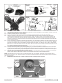
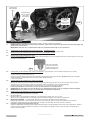
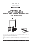
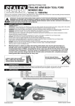
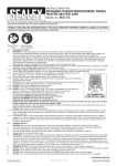
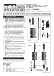
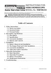
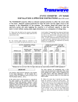
1
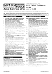
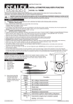
INSTRUCTIONS FOR: COMPRESSOR 200LTR BELT DRIVE 3.0HP 415V/3PH WITH FRONT CONTROL PANEL MODEL NO: SAC3203B3PH Thank you for purchasing a Sealey product. Manufactured to a high standard, this product will, if used according to these instructions and properly maintained, give you years of trouble free performance. IMPORTANT: PLEASE READ THESE INSTRUCTIONS CAREFULLY. NOTE THE SAFE OPERATIONAL REQUIREMENTS, WARNINGS & CAUTIONS. USE THE PRODUCT CORRECTLY AND WITH CARE FOR THE PURPOSE FOR WHICH IT IS INTENDED. FAILURE TO DO SO MAY CAUSE DAMAGE AND/OR PERSONAL INJURY AND WILL INVALIDATE THE WARRANTY. KEEP THESE INSTRUCTIONS SAFE FOR FUTURE USE. 1. SAFETY 1.1 ELECTRICAL SAFETY. WARNING! It is the user’s responsibility to read, understand and comply with the following: You must check all electrical equipment and appliances to ensure they are safe before using. You must inspect power supply leads, plugs and all electrical connections for wear and damage. You must ensure the risk of electric shock is minimised by the installation of appropriate safety devices. An RCCB (Residual Current Circuit Breaker) should be incorporated in the main distribution board. We also recommend that an RCD (Residual Current Device) is used with all electrical products. It is particularly important to use an RCD together with portable products that are plugged into an electrical supply not protected by an RCCB. If in doubt consult a professional electrician. You may obtain a Residual Current Device by contacting your Sealey dealer. You must also read and understand the following instructions concerning electrical safety. 1.1.1 The Electricity At Work Act 1989 requires all portable electrical appliances, if used on business premises, to be tested by a qualified Electrician at least once a year, using a Portable Appliance Tester (PAT). 1.1.2The Health & Safety at Work Act 1974 makes owners of electrical appliances responsible for the safe condition of the appliance, and the safety of the appliance operator. If in any doubt about electrical safety, contact a qualified Electrician. 1.1.3 Ensure the insulation on all cables and the product itself is safe before connecting to the mains power supply. See 1.1.1. & 1.1.2. above and use a Portable Appliance Tester (PAT). 1.1.4 Ensure that cables are always protected against short circuit and overload. 1.1.5 Regularly inspect power supply, leads, plugs and all electrical connections for wear and damage, especially power connections, to ensure that none are loose. 1.1.6 Important: Ensure the voltage marked on the product is the same as the electrical power supply to be used and check that plugs are fitted with the correct capacity fuse. If an electrical fuse blows, ensure it is replaced with an identical fuse type and rating. 1.1.7 DO NOT pull or carry the powered appliance by its power supply lead or output cables. 1.1.8 DO NOT pull power plugs from sockets by the power cable. 1.1.9 DO NOT use worn or damage leads, plugs or connections. Immediately replace or have repaired by a qualified Electrician. This particular compressor is supplied without a mains plug. Follow the instructions below regarding the fitting of an appropriate plug. 1.2 MODEL SAC3203B3PH REQUIRES A 415V 3 PHASE SUPPLY AND MUST HAVE AN APPROPRIATE PLUG FITTED. WARNING! ELECTRICAL INSTALLATION OF THE COMPRESSOR TO A 3 PHASE 415VOLT SUPPLY MUST ONLY BE CARRIED OUT BY A QUALIFIED ELECTRICIAN. Ensure the power supply cable is connected to the Earth. 1.2.1 This product must be fitted with a 3 phase plug wired as illustration in (fig.2), wired to an appropriately fused supply. Connect GREEN/YELLOW wire to Earth ‘E’ Connect BROWN wire to L1 Terminal.* Connect BLACK wire to L2 Terminal.* Connect the GREY wire to L3 Terminal.* *NOTE: The cable core colours found in the mains cable on this compressor are consistent with Amendment 2 to 7671:2001. When completed, check there are no bare wires, that all wires have been connected correctly and the cable restraint is tight. WARNING! IT IS ESSENTIAL TO OBSERVE ANTI-CLOCKWISE (fig.1) PULLEY DIRECTION ON INITIAL START UP. IF CLOCKWISE OBSERVED, STOP IMMEDIATELY AND CONSULT A QUALIFIED ELECTRICIAN TO INVERT 2 PHASES. 1.2.2 DO NOT use this product with a standard extension cable. Only use ARMOURED extension cable IMPORTANT USER INFORMATION! Over-current protection of the power circuit is required in accordance with 7.2 of EN 60204-1:2006. The supply disconnecting device to be in accordance with 5.3 of EN60204-1:2006. Ask a qualified electrician about compliance. The use of extension leads to connect these compressors to the mains is not recommended. Control Panel Switches IMPORTANT! (fig.7) Pump (fig.8) Anti-clockwise (fig.5) rotation (label on guard) see 1.2.1 fig.2 Motor 3~ph (Grey) to L3 Ball valve Non return valve 'E' Earth green/yellow From pump Mains cable To receiver (Black) to L2 Decompression tube from switch (Brown) to L1 Receiver 2-Pneumatic tyres 1.5bar Hose reel tidy © Jack Sealey Limited Swivel castor with brake fig.1 Original Language Version SAC3203B3PH Issue No: 1 - 27/10/14 1.3. GENERAL SAFETY 3 Familiarise yourself with the application and limitations of the compressor. 3 Ensure the compressor is in good order and condition before use. If in any doubt DO NOT use the unit and contact an electrician/ service agent. WARNING! The Compressor must only be serviced by an authorised agent. DO NOT tamper with, or attempt to adjust, pressure switch or safety valve. 3 Before moving, or maintaining the compressor ensure it is unplugged from the mains supply and that the air tank pressure has been vented. 3 Maintain the compressor in good condition and replace any damaged or worn parts. Use genuine parts only. Unauthorised parts may be dangerous and will invalidate your warranty. 3 Read the instructions relating to any accessory to be used with this compressor. Ensure the safe working pressure of any air appliance used exceeds compressors output pressure. If using a spray a gun, check that the area selected for spraying is provided with an air change/ventilation system. 3 Ensure the air supply valve is turned off before disconnecting the air supply hose. 3 Move the compressor on a pallet or using slings beneath receiver near to domed ends, employing a fork lift truck or wheeled gantry crane. Beware of off centre loads. 3 Use the compressor in a well ventilated area and ensure it is placed on a firm surface. 3 Keep tools and other items away from the compressor when it is in use, and keep area clean and clear of unnecessary items. 3 Ensure the air hose is not tangled, twisted or pinched. 3 Keep children and unauthorised persons away from the working area. 3 When not in use, store the compressor carefully in a safe, dry, childproof location. 7 DO NOT disassemble compressor for any reason. The unit must be checked by qualified personnel only. 7 DO NOT use the compressor outdoors, or in damp, or wet, locations. 7 DO NOT operate the compressor within the vicinity of flammable liquids, gases or solids. 7 DO NOT touch the compressor cylinder head or pipe from the head to tank as these may be hot. 7 DO NOT use this compressor to perform a task for which it has not been designed. 7 DO NOT deface the certification plate attached to the compressor tank. 7 DO NOT cover the compressor or restrict air flow around the unit whilst operating. q DANGER! DO NOT direct the output jet of air towards people or animals. 7 DO NOT operate the compressor without an air filter. 7 DO NOT allow anyone to operate the compressor unless they have received full instructions. WARNING! The air tank is a pressure vessel and the following safety measures apply: 7 DO NOT tamper with the safety valve, DO NOT modify or alter the tank in any way and DO NOT strap anything to the tank. 7 DO NOT subject the tank to impact, vibration or to heat and no welding operations are to be carried out on any pressurised parts of the vessel. DO NOT allow contact with abrasives or corrosives. 2. INTRODUCTION V-pump belt driven compressor, 200ltr. The pump features heavy duty fully cast cylinders, capped by alloy heads for improved heat dissipation and long life. Suitable for professional workshop applications. The 2 cylinder pump is powered by a 415v 3ph 3.0hp motor. A precision, continuously welded receiver tank manufactured to meet Pressure Vessel Directive 2009/105/EC. Fitted with fully automatic pressure cut-out switch and receiver drain valve. Supplied with 2 pneumatic tyred wheels, a leading swivel castor, fixings and 4 core 2.5 metre flying lead. 3. SPECIFICATION MODEL:.......................................................................SAC3203B3PH Motor output:......................................................................2.2kW/3hp Voltage/phase:................................................................... 415V - 3ph Rated supply:...................................................................................6A Speed at pump:.....................................................................1243rpm Noise level:.............................................................................96dB(A) Air displacement cfm (ltr/min):......................................... 13.4 (380) Maximum free air delivery cfm (ltr/min):.......................... 10.9 (310) Tank capacity:.............................................................................200ltr Max pressure:................................................................145psi /10bar Weight:....................................................................................... 103kg Dimensions (W x D x H):................................1410 x 600 x 1020mm 4. ASSEMBLY 4.1. 4.2. 4.3. 4.4. 4.5. 4.6. 4.7. 4.8. Remove compressor from packaging and inspect for any shortages or damage. If anything is found to be missing or damaged contact your supplier. Save the packing material for future transportation of the compressor. We recommend that you store the packing in a safe location, at least for the period of the guarantee. Then, if necessary, it will be easier to send the compressor to the service centre. Confirm that the mains voltage corresponds with the voltage shown on the compressor data plate. Assemble the 2 wheels and leading swivel castor, using the nuts, bolts and washers supplied (fig.4). The compressor should be operated on a flat surface, or one that does not exceed 5° either transversely or longitudinally and should be in a position that allows good air circulation around the unit, (see 1000mm nominal perimeter in fig.6). Before using the compressor check the oil level by referring to the oil sight glass (fig.5C). On a horizontal surface, if the oil level is not up to the red centre mark it should be further topped up with recommended oil (See section 6.7). To top up unscrew plug (fig.5B). Screw the back half of a filter unit into the port openings in each head as shown in (fig.5A and fig.3). Place a filter cover over each threaded rod protruding from the back half of the filter and secure each with a wing nut. Check the drain valve is fully closed (fig.9) 5. OPERATION 5.1. 5.2. WARNING! Ensure that you have read, understood and apply Section 1 safety instructions. IMPORTANT. The use of extension leads to connect this compressor to the mains is not recommended as the resulting voltage drop reduces motor, and therefore pump, performance and could damage your compressor. Take care when selecting tools for use with the compressor. Air tool manufacturers normally express the volume of air required to operate a tool in cubic feet per minute (cfm). This refers to free air delivered by the compressor (‘air out’) which varies according to the pressure setting. Do not confuse this with the compressor displacement which is the air taken in by the compressor (‘air in’). ‘Air out’ is always less than ‘air in’ due to losses within the compressor. © Jack Sealey Limited Original Language Version SAC3203B3PH Issue No: 1 - 27/10/14 fig.4 Receiver leg Plain washer. Spring washer/ nut Axle bolt Spacers Wheel fig.3 Breather (at rear) C Fully inflated 1.5bar 5° max 5° max Drain plug Swivel castor Chocks A fig.5 Plain washer/ spring washer/ spacer. Bolt fig.6 B A Nut/spring washer Receiver leg Wall 1000mm nominal PUMP 5.3. STARTING THE COMPRESSOR. 5.3.1. Your compressor is fitted with two push buttons for on/off switching. To turn the compressor on push the green "on" button.To turn the compressor off push the red "off" button. (See fig.8) 5.3.2. Check that the on/off switch is in the “off” position. 5.3.3. Plug the mains lead into mains supply and start the compressor by pushing the green "on" button (fig.8) downwards. 5.3.4.Leave the compressor running with no air line or tools connected. Make sure that the pressure in the tank rises and that the compressor stops automatically when the maximum pressure is reached. This value is written on the specification plate and may take in excess of 5 minutes.The compressor will now operate automatically. The pressure switch (fig.8) stops the motor when the maximum tank pressure is reached and restarts it when pressure falls below the minimum threshold approximately 2bar (29psi) less than the maximum pressure. 5.3.5. Stop the compressor by pushing the red "off" button (fig.8) downwards. The compressed air inside the compressor head will flow out via the air line tube situated beneath the switch housing. Restart is made easier and prevents the motor from being damaged. DO NOT, other than in an emergency, stop the compressor by switching off the mains power, or by pulling the plug out, as the pressure relief will not then occur and motor damage may result upon restart. When the compressor runs correctly and is stopped correctly there will be: (a) A whistle of compressed air when the motor stops, (b) A protracted whistle (about 20-25 seconds) when the compressor starts with no pressure in the tank. 5.3.6. The output pressure is regulated by the pressure regulator (fig.7). Turn the knob clockwise to increase pressure and anti-clockwise to reduce it. The knob can be locked at any required setting by tightening the locking ring against the underside of the knob. The required pressure is determined by the pneumatic appliance user manual. When the compressor is not being used, set the regulated pressure to zero, hence avoiding damage to the pressure reducer. 5.3.7. Two quick release supply sockets offer either full receiver pressure or a regulated supply pressure up to a maximum of the receiver pressure. A third option 1/4"BSP female connection is via the receiver ball valve (fig.1) with unregulated pressure. NOTE: If the motor does not cut in and out, but runs continuously when using an air appliance, the capacity of the compressor may be too small for the equipment or tool. Should the pressure in the main tank exceed the pressure switch pre-set pressure maximum, the safety valve (fig.8) will activate. WARNING! DO NOT tamper with, or adjust, the pressure switch or safety pressure relief valve. RECEIVER PRESSURE REGULATED PRESSURE Control Panel Gauges REGULATOR UNREGULATED SUPPLY © Jack Sealey Limited fig.7 Original Language Version REGULATED SUPPLY SAC3203B3PH Issue No: 1 - 27/10/14 Control Panel and ancilliaries (fig.7) Pressure switch and "On" (green) "OFF" (red) Push buttons IMPORTANT! Anti-clockwise rotation (label on guard) see 1.2.1 Safety pressure relief valve Receiver Utility brackets fig.8 6. MAINTENANCE 6.1. 6.2. 6.3. In order to keep the compressor in good working condition, periodic maintenance is essential. WARNING! Before performing any maintenance operation, switch off the compressor, disconnect from electricity supply and release all air from the tank. IMPORTANT! Failure to carry out maintenance tasks may invalidate the warranty on your compressor. OPERATIONS TO BE CARRIED OUT AFTER THE FIRST 5 WORKING HOURS: a) Check that all bolts/nuts are tight, particularly those retaining the crank case and cylinder head. OPERATIONS TO BE CARRIED OUT AFTER THE FIRST 50 WORKING HOURS: b) Replace the lubricating oil - see para 6.5. OPERATIONS TO BE CARRIED OUT DAILY: a) Drain condensation by opening the valve located under the tank (fig.9). Place a container under the valve and slowly open the valve by turning counterclockwise. fig.9 Drain valve underside of receiver, ensure it is closed on start up (4.8) and drained daily (6.3.). 6.4. OPERATIONS TO BE CARRIED OUT EVERY 100 HOURS (or more frequently, if the compressor operates in a very dusty atmosphere) a) Check oil level and, if necessary, top up. b) Remove the filter elements (See fig.3) and clean with compressed air (wear eye protection). DO NOT operate the compressor without the filters as foreign bodies or dust could seriously damage the pump. c) Check for oil leaks. 6.5. OPERATIONS TO BE CARRIED OUT EVERY 200 HOURS: a) Replace the lubricating oil. For oil specifications see 6.7. Remove the oil filler plug (see fig 5.B) then unscrew oil drain plug (see fig.5) and drain the oil into a container. Drain when the compressor is hot so that oil drains rapidly and completely. Incline compressor to ensure complete drainage. Replace oil drain plug and refill through the oil filler aperture. Do not overfill. Replace oil filler plug. b) Check the automatic cut-out at max. pressure and the automatic cut-in at 2bar below. WARNING!Never mix different oils and DO NOT use non-detergent/low quality oils as the compressor may be damaged. WARNING! Dispose of waste oil only in accordance with local authority requirements. 6.6. OPERATIONS TO BE CARRIED OUT EVERY 500 HOURS: a) Replace air filter. (See fig.3) b) Check all tube fittings and electrical connections. 6.7. Recommended oils; Recommended oil for compressors, suitable for room temperatures ranging from +5°C to +25°C. SEALEY CPO or equivalent SAE 40 compressor oil. Room temperature below +5°C: SAE 20 compressor oil. 6.8 IMPORTANT WARNING - Air contaminants taken into the compressor will affect optimum performance. Example: Body filler dust or paint overspray will clog the pump intake filter and may cause internal damage to pump/motor components. Please note that any parts damaged by any type of contamination will not be covered by warranty. 6.9 Inspection of pressure tank both inside and out. Under the PRESSURE SYSTEMS SAFETY REGULATIONS 2000 it is the responsibility of the owner of the compressor to initiate a system of inspection that both defines the frequency of the inspection and appoints a person who has specific responsibility for carrying out the inspection. © Jack Sealey Limited Original Language Version SAC3203B3PH Issue No: 1 - 27/10/14 7. TROUBLESHOOTING POSSIBLE CAUSE REMEDY 1A) Pressure drop in the tank FAULT Air leaks at connections Run compressor to max. pressure, switch off. Brush soap solution over connections and look for bubbles. Tighten connections showing leaks. If problem persists contact Authorised Service Agent 1B) Pressure drop in the tank Air leaks from safety valve It should be replaced, unless leaking at a joint which can be sealed. 1C) Pressure drop in the tank Air leaks from cylinder head gasket Check tightness of head bolts. If leak continues contact authorised Service Agent Non-return valve seal defective Empty the air tank. Referring to fig.10, remove the non-return valve cap (3), spring (2) and seal (1). Clean the seal and its seat, or if necessary replace the seal Internal corrosion caused by infrequent tank draining or non permitted modifications to tank Tank could rupture or explode. Cannot be repaired DISCONTINUE USE IMMEDIATELY 2) Pressure switch valve leaks when compressor is idle 3) Air leaks from tank body or tank welds 4A) Motor stops and will not restart Thermal cut out has operated Allow unit to cool for 30 minutes before restarting 4B) Motor stops and will not restart Supply has tripped Press trip reset and restart unit. If repeated tripping occurs replace the check valve or contact authorised Service Agent Motor failure Contact Authorised Service Agent 6A) Compressor does not stop at max. pressure Pressure switch fault Contact Authorised Service Agent 6B) Compressor does not stop at max. pressure Filter clogged Head gasket or valve fault Replace filter element. Contact Authorised Service Agent 7) Compressor noisy with metallic knock Bearing or piston damage Contact Authorised Service Agent 8) Excessive moisture in discharged air High humidity environment Drain tank after each use 5) Compressor stops and does not restart Located on tank, see also 7.2 fig.10 Environmental Protection Recycle unwanted materials instead of disposing of them as waste. All tools, accessories and packaging should be sorted, taken to a recycling centre and disposed of in a manner which is compatible with the environment. When the product becomes completely unserviceable and requires disposal, drain off any fluids (if applicable) into approved containers and dispose of the product and the fluids according to local regulations. WEEE Regulations Dispose of this product at the end of its working life in compliance with the EU Directive on Waste Electrical and Electronic Equipment (WEEE). When the product is no longer required, it must be disposed of in an environmentally protective way. Contact your local solid waste authority for recycling information. Parts support is available for this product. To obtain a parts listing and/or diagram, please log on to www.sealey.co.uk, email [email protected] or telephone 01284 757500. NOTE: It is our policy to continually improve products and as such we reserve the right to alter data, specifications and component parts without prior notice. IMPORTANT: No liability is accepted for incorrect use of this product. WARRANTY: Guarantee is 24 months from purchase date, proof of which will be required for any claim. INFORMATION: For a copy of our latest catalogue and promotions call us on 01284 757525 and leave your full name and address, including postcode. Sole UK Distributor, Sealey Group, Kempson Way, Suffolk Business Park, Bury St. Edmunds, Suffolk, IP32 7AR © Jack Sealey Limited Original Language Version 01284 757500 01284 703534 Web email www.sealey.co.uk [email protected] SAC3203B3PH Issue No: 1 - 27/10/14 © Jack Sealey Limited Original Language Version SAC3203B3PH Issue No: 1 - 27/10/14