1
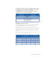
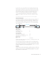
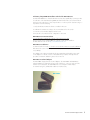
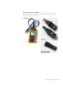
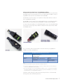
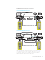
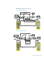
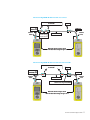
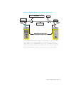
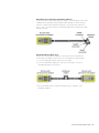
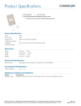
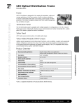
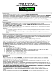
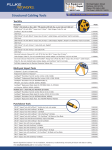
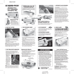
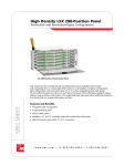
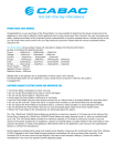
SYSTIMAX® Solutions
Performance Verification of GigaSPEED® XL
Installations with Fluke Networks DSP-4x00
Series Testers
February 2004
www.commscope.com
The SYSTIMAX® GigaSPEED® XL Solutions and their performance specifications
are offered in two versions, depending on the GigaSPEED XL cable type used.
The GigaSPEED XL7 Solution utilizes 71E series cables and
the GigaSPEED XL8 Solution utilizes 81A series cables. The GigaSPEED XL
components for each solution are listed in the table below.
GigaSPEED XL7 Solution
GigaSPEED XL8 Solution
71E Series Cables
(1071E/2071E/3071E)
81A Series Cables
(1081A/2081A/3081A)
MGS400 Modular Outlets
PATCHMAX® GS3 Modular Patch Panels
1100 GS3 Modular Patch Panels
iPatch® GS3 Modular Patch Panels
VisiPatch® GS3 Cross-connect Systems
GS8E Modular Cord Family
GigaSPEED XL Guaranteed Channel Performance
Registered GigaSPEED XL installations in conformance with the relevant SYSTIMAX guidelines
are covered by the SYSTIMAX 20 Year Assurance Program, and are also backed by the
GigaSPEED XL Minimum Channel Performance Guarantees up to 250 MHz.
The GigaSPEED XL Minimum Channel Performance Guarantees exceed the Category 6
channel specifications in TIA 568B.2-1 and the Class E channel specifications in the ISO/IEC
11801 2nd Ed. (2002) by significant margins on a swept frequency basis, as outlined in the
SYSTIMAX Labs memorandum entitled “SYSTIMAX® GigaSPEED® XL7/8 Channel Performance
Specifications”.
GigaSPEED XL guaranteed channel performance margins for 4 and 6-connector channels over
the entire frequency range (1-250 MHz) are listed below:
4-Connector Channel
Guaranteed Margin
GigaSPEED XL7
GigaSPEED XL8
Insertion Loss
5%
NEXT
6 dB
PSNEXT
ELFEXT
6-Connector Channel
Guaranteed Margin
GigaSPEED XL7
GigaSPEED XL8
7.5 %
4%
6.5 %
7 dB
4 dB
5 dB
7.5 dB
8.5 dB
5.5 dB
6.5 dB
6 dB
8 dB
4 dB
6 dB
PSELFEXT
8 dB
10 dB
6 dB
8 dB
Return Loss
4 dB
4 dB
2 dB
2 dB
www.commscope.com
2
Performance Testing of SYSTIMAX Installations
For installations designed and registered by a SYSTIMAX-certified BusinessPartner in
accordance with the relevant SYSTIMAX Design and Installation guidelines, CommScope
guarantees end-to-end channel performance. Therefore, CommScope does not require
certification testing for SYSTIMAX installations. Wire map testing is the minimum mandatory
requirement.
However, many customers request performance testing of a percentage or all of the installed
links and/or channels. CommScope is fully supportive of field testing practices and has
provided valuable contributions to standards developments and test set manufacturers to enable
the accurate testing of SYSTIMAX installations.
Test Configurations
Cabling standards define the following test configurations for installed cabling:
The Channel configuration includes all the end-to-end cabling components necessary to
interconnect two communications devices. Therefore, channel performance determines the
overall quality of the communications and provides a true indication of end-to-end cabling
system performance. All applications refer to end-to-end channel performance.
The Permanent Link configuration only includes the “permanently” installed cabling (no cords
or crossconects). (Note: ISO/IEC 11801 2nd Ed. additionally defines a length-dependent CP
Link configuration for testing of cabling up to the Consolidation Point).
CommScope supports both Permanent Link and Channel testing. Permanent Link tests are most
commonly performed by installers, since channel tests should be performed with the cords that
will remain in-situ for each channel. However, applications rely on end-to-end cabling system
channel performance. Therefore, the Guaranteed GigaSPEED XL Channel Performance margins
apply to GigaSPEED XL channel configurations.
Channel Configuration
The Channel configuration is intended to be used by system designers, installers, and users of
data telecommunications systems to verify the end-to-end performance of cabling systems. It is
important to note that the Channel includes the work area cords, equipment cords and crossconnects that make up the end-to-end cabling system.
Channel under test
Work area
equipment
A
B
WA
C
D
CP
Cables and cords
Work area cord Optional transition cabling Horizontal cabling Patch cord Telecom Room/Floor Distributor Horizontal cross-connect or equipment cord C1
E
Equipment
in TR/FD
C2
A
B
C
D
E
Connecting hardware
Telecommunications outlet/connector Optional transition/consolidation point connector.
Horizontal cross-connect or interconnect.
WA
CP
C1, C2
Maximum length
B + C.
A + D + E
90 m (295 ft)
10 m (32.8 ft)
www.commscope.com
3
The elements of the common channel definition found in TIA-568B, and ISO/IEC 11801
2nd Ed. are shown in the figure above. The 4-connector channel limits are based on 90 m
of horizontal cable, a work area cord, a telecommunications outlet/connector, an optional
transition point close to the work area, and across-connect in the telecommunications closet.
The combined length of equipment cords, patch cords, and jumpers shall not exceed
10 meters. A 15 m minimum length of cable between CP and C1 in the figure above
is recommended by TIA/EIA 568B, and is required by ISO/IEC 11801 2nd Ed. The
connections to the equipment at each end of the channel are not included in the channel
definition.
Note: The ISO/IEC 11801 2nd Ed. also includes 2-connector and 3-connector channel configurations
Permanent Link Configuration
The Permanent Link configuration is intended to be used by system designers, installers, and
users of data telecommunications systems to verify the performance of cabling installed
between the telecommunications closet and the work area outlet. It is important to note that
the Permanent Link configuration includes the optional Consolidation Point (if present) but
does not include the work area cords, equipment cords, or cross-connects that make up the
end-to-end cabling system.
Permanent Link
Field test
instrument
F
E
WA
C
F
CP
Field test
instrument
C1
Cables and cords
Test equipment cord Optional transition cabling Horizontal cabling F
B
C
Connecting hardware
Telecommunications outlet/connector Optional transition/consolidation point connector.
Horizontal cross-connect or interconnect.
WA
CP
C1
Maximum length
B + C.
90 m (295 ft)
A schematic representation of the Permanent Link definition in TIA-568B and ISO/IEC 11801
2nd Ed. is shown in the figure above.
The Permanent Link limits are based on up to 90 m (295 ft) of horizontal cabling and up to
3 connections (including the optional Consolidation Point). A 15 m minimum length of cable
between CP and C1 in the figure above is recommended by TIA/EIA 568B, and is required
by ISO/IEC 11801 2nd Ed. The Permanent Link excludes both the cable portion of the field
test instrument cord and the connection to the field test instrument.
The CP Link
The CP Link defined in ISO/IEC 11801 2nd Ed. is intended for testing of Consolidation Point
installations in cases where the transition cabling (labelled B in the figure above) is not present.
The CP Link test limits for insertion loss, ACR, PSACR, ELFEXT, PSELFEXT, d.c. loop resistance,
delay, and delay skew are length-dependent.
www.commscope.com
4
Field Testing of GigaSPEED XL Installations with the Fluke DSP-4x00 Series
The Fluke DSP-4x00 Series of hand held instruments have been qualified by CommScope Labs
for verification of the Guaranteed GigaSPEED XL Channel Performance as well as Permanent
Link testing to the Category 6 / Class E specifications. In order to perform accurate testing, it is
important to ensure the following:
1. Verify that the latest instrument software is installed in the tester
2. Calibrate the instrument according to the recommendations from the vendor
3. Select the correct interface adapters and test cords
4. Execute the correct Autotest for the configuration to be tested
DSP-4x00 Series Instrument Software
It is very important to maintain the software of the instrument up-to-date.
The most recent versions of DSP-4x00 series software can be downloaded form
the Fluke Networks web site at http://www.flukenetworks.com
DSP-4x00 Series Calibration
To obtain accurate test results, it is critical to ensure that the instrument is properly calibrated.
Fluke Networks recommends factory calibration every twelve months, and field calibrations
every 30 days.
The calibration procedures are detailed in the User Manual provided with the tester and/
or test adapters. For a brief overview of field calibration procedures and a quick-check
procedure of instrument calibration, please refer to Annex A.
DSP-4x00 series Channel Adapters
The DSP-4x00 is shipped with two channel adapters. The DSP-LIA012 and DSP-LIA013
Channel Adapters (see figure below) have “RJ45” interfaces to connect to each end of the
channel to be tested. (Note: The DSP-LIA013 has a second jack for traffic analysis.
For channel testing, the jack labelled “Cable Test” must be used).
DSP-LIA012
DSP-LIA013
www.commscope.com
5
DSP-4x00 series Permanent Link Adapters
For Permanent Link testing, the DSP-4x00 series utilizes a Universal Permanent Link Adapter
(DSPLIA101S) and Personality Modules with either modular or 110 plugs to connect to the
Permanent Link under test (see figures below).
www.commscope.com
6
Verifying Permanent Link Performance of GigaSPEED XL installations
For Permanent Link performance testing, a properly calibrated DSP-LIA101 Universal Permanent
Link Adapter must be used. Currently there are two Personality Modules available for testing of
GigaSPEED XL Permanent Links: the DSP-PM25 and the DSP-PM06.
The DSP-PM25 was the first Category 6 compliant Personality Module and was constructed
with a GigaSPEED XL GS8E plug.
The DSP-PM06 is a newer Category 6 Personality Module based on a centered plug designed by
Fluke Networks, and is expected to replace the DSP-PM25 in the Fluke Networks catalogue.
For testing of VisiPatch installations, the DSP-PM10B (T568B wiring) or the DSP-PM10A (T568A
wiring) can be used. The figures below illustrate the different DSP Personality Modules suitable
for SYSTIMAX Solutions.
The correct Autotest and Personality Modules for Permanent Link testing of GigaSPEED XL
installations are listed in the table below:
GigaSPEED XL Permanent Link Performance Testing
Autotest
TIA Cat 6 Perm. Link1
ISO11801 PL max Class E2
EN50173 PL Class E2
Personality
Modules
Modular Hardware
(MGS400, 1100GS3, PatchMAX GS3)
DSP-PM063
DSP-PM253
VisiPatch Panels
DSP-PM10B (T568B) or
DSP-PM10A (T568A)
Notes:
1. The TIA Cat 6 Permanent Link autotest incorporates a 3 dB rule for Return Loss
2. The IS11801 and EN50173 Perm Link autotests incorporate a 3 dB rule for Return Loss, and a 4 dB rule for
Insertion Loss, NEXT, PSNEXT, ACR, and PSACR.
3. Either Personality Module can be used for GigaSPEED XL installations, but as it is expected that the DSP-PM06
will replace the DSP-PM25 in the Fluke Networks catalog going forward, the DSP-PM06 is the recommended
Personality Module for newer GigaSPEED XL installations.
Compliance with the Category 6/Class E Permanent Link specifications is demonstrated by
achieving PASS results for all autotest parameters.
www.commscope.com
7
GigaSPEED XL Permanent Link configurations are shown below.
2-Connector GigaSPEED XL Permanent Link
DSP -PM06
-PM25 or
DSP -PM25
-PM02 or
DSP -PM10A or
DSP -PM10B
MGS400, PatchMAX GS3, 1100 GS3,
or VisiPatch
MGS400
1
2
Perm Link Start
DSP -LIA101
DSP -PM06
-PM25 or
DSP -PM25
-PM02
Perm Link End
71E or 81A Cable
DSP -LIA101
Maximum Permanent Link Length = 90 m
3-Connector GigaSPEED XL Permanent Link
DSP -PM06
-PM25 or
DSP -PM25
-PM02 or
DSP -PM10A or
DSP -PM10B
MGS400, PatchMAX GS3, 1100 GS3,
or VisiPatch
1
MGS400
2
3
Perm Link Start
DSP -LIA101
DSP -PM06
-PM25 or
DSP -PM25
-PM02
Perm Link End
71E or 81A Cable
DSP -LIA101
GS8MGS or MGS400 connector terminated on
GS3117 Cord or single ended GS8E
Maximum Permanent Link Length = 90 m
Additionally, building backbone permanent links and CP links may also be tested according
to these guidelines. If CP Links are tested as per ISO/IEC 11801 2nd Ed., it is necessary
to verify that there is sufficient insertion loss and delay skew margin to accommodate any
additional cabling, and/or label the CP links according to length.
www.commscope.com
8
Verifying Channel Performance of GigaSPEED XL Installations
Compliance of installed GigaSPEED XL Channels with the Guaranteed GigaSPEED XL Channel
Performance margins may be verified once the SYSTIMAX Work Area Cords, Patch Cords and
Equipment cords are installed. For Channel performance testing, the channel adapters provided
with the DSP-4x00 series instruments must be used to interface to the GigaSPEED XL cords at
each end of the channel.
The correct Autotests and adapters for GigaSPEED XL channel testing are listed in the
table below:
GigaSPEED XL Permanent Link Performance Testing
Autotest
TIA Cat 6 Channel1
ISO11801 Channel Class E2
EN50173 Ch Class E2
Channel Adapters
DSP-LIA012
DSP-LIA013
Notes:
1. The TIA Cat 6 Channel autotest incorporates a 3 dB rule for Return Loss
2. The IS11801 and EN50173 autotests incorporate a 3 dB rule for Return Loss, and a 4 dB rule for Insertion
Loss, NEXT, and PSNEXT .
Compliance with the guaranteed GigaSPEED XL channel performance specifications is
achieved by channel test results that show PASS for all Category 6 / Class E requirements
and performance margin that is equal to or better than the GigaSPEED XL Guaranteed
Channel Margin.
www.commscope.com
9
GigaSPEED XL Channel Configurations are shown below.
4-Connector GigaSPEED XL Channel
MGS400, PatchMAX GS3, 1100 GS3,
or VisiPatch
GS8E Cord
or
GS3117 Cord
Channel
Start
1
2
MGS400
4
3
GS8E Cord
GS8E Cord
110VP8-GS3 Cord
or
119VP8-GS3 Cord
Channel
End
71E or 81A Cable
GS8MGS or MGS400 connector terminated on
GS3117 Cord or single ended GS8E
Maximum Channel Length = 100 m
Maximum Stranded Cordage Length = 10 m
6-Connector GigaSPEED XL Channel
GS8E Cord
or
119VP8-GS3 Cord
MGS400, PatchMAX GS3, 1100 GS3,
or VisiPatch
1
2
3
4
MGS400
5
6
GS8E Cord
Channel
Start
Channel
End
71E or 81A Cable
GS8E Cord
110VP8-GS3 Cord
or
119VP8-GS3 Cord
Maximum Channel Length = 100 m
Maximum Stranded Cordage Length = 10 m
www.commscope.com 10
3-Connector GigaSPEED XL Channel with cross-connect
MGS400, PatchMAX GS3, 1100 GS3,
or VisiPatch
GS8E Cord
or
GS3117 Cord
Channel
Start
1
2
MGS400
3
GS8E Cord
GS8E Cord
110VP8-GS3 Cord
or
119VP8-GS3 Cord
Channel
End
71E or 81A Cable
Maximum Channel Length = 100 m
Maximum Stranded Cordage Length = 10 m
3-Connector GigaSPEED XL Channel with interconnect and CP
MGS400, PatchMAX GS3, 1100 GS3,
or VisiPatch
GS8E Cord
or
119VP8-GS3 Cord
Channel
Start
1
2
MGS400
3
GS8E Cord
Channel
End
71E or 81A Cable
GS8MGS or MGS400 connector terminated on
GS3117 Cord or single ended GS8E
Maximum Channel Length = 100 m
Maximum Stranded Cordage Length = 10 m
www.commscope.com 11
2-Connector GigaSPEED XL Channel (Interconnect at FD/TC, no CP)
MGS400, PatchMAX GS3, 1100 GS3,
or VisiPatch
GS8E Cord
or
119VP8-GS3 Cord
Channel
Start
1
MGS400
2
GS8E Cord
Channel
End
71E or 81A Cable
Maximum Channel Length = 100 m
Maximum Stranded Cordage Length = 10 m
Since GigaSPEED XL allows for the construction of channels with up to six connectors, several
other configurations are also allowed in addition to the configurations shown above (for
example, other 6 connector configurations as well as 5 connector configurations are allowed
and may also be tested according to the same guidelines, but are not shown in this document).
Additionally, building backbone channels may also be tested according to these guidelines.
www.commscope.com 12
Annex A – Field calibrations and Quick Instrument Check
Proper calibration is a critical requirement for accurate test results.
Fluke Networks recommends that the tester be calibrated at the
factory every 12 months, and field calibrations (self-calibration)
to be performed every 30 days.
Self Calibration
To perform a Self Calibration, follow these steps.
1. C
onnect the Main to the Remote with the DSPCAL module
provided with the tester as shown in the adjacent figure.
2. Run the Self Calibration in SPECIAL FUNCTIONS
3. Run the Self Test in SPECIAL FUNCTIONS
Self Calibration Quick Check
After a self calibration, you can obtain an indication
that the instrument is performing within specification
with this simple sanity check:
DSPCAL
Module
1. Set the standard to TIA Cat 6 Channel
2. Run the AUTOTEST.
3. C
heck the NEXT and RL margins:
4 NEXT margin should be > 20 dB
4 RL margin should be > 19 dB
Channel Calibration Quick Check
A quick check of channel calibration may also be performed with
a GS8E cord as shown in the figure below. This is a complete
calibration check that includes the channel adapters.
Quick check procedure:
1. Set the standard to TIA Cat 6 Channel
2. Run the AUTOTEST.
3 m GS8E
3. C
heck the results:
4 Insertion Loss should be < 2 dB
4 NEXT margin should be > 15 dB
4 RL margin should be > 15 dB
4 ELFEXT margin should be > 15 dB
Note: when performing this check, ensure that the GS8E cord is in
good condition, and not tightly coiled, sharply bent, or otherwise
damaged.
www.commscope.com 13
DSP-4x00 Permanent Link Adapter (DSP-LIA101) Calibration
To achieve the best Permanent Link accuracy for Return Loss, the DSP-LIA101 must be field
calibrated with the DSP-PLCAL artifact and Fluke Cable Manager™ software as per the
instructions included with the DSP-PLCAL artifact (by connecting the Main and Remote
units to “open”, “short” and “load” in the DSP-PLCAL artifact when prompted by the Cable
Manager software).
DSP-LIA101 Calibration Quick Check
A quick check of Permanent Link calibration may be performed as described below.
The Permanent Link calibration quick check does not include the Personality Modules.
1. Select the “DSP-LIA101 Self Test” Autotest in the DSP Setup.
2. C
onnect the DSP-LIA101 adapter from each unit to the “through” connection in
the DSP-PLCAL artifact as shown below
3. R un the DSP-LIA101 Autotest. A PASS result indicates proper calibration of the
DSP-LIA101 Adapters.
www.commscope.com 14
www.commscope.com
Visit our Web site or contact your local
CommScope representative for more information.
© 2011 CommScope, Inc. All rights reserved.
All trademarks identified by ® or ™ are registered trademarks
or trademarks, respectively, of CommScope, Inc.
This document is for planning purposes only and is not
intended to modify or supplement any specifications or
warranties relating to CommScope products or services.
09/11