1
MODBUS/TCP Interface Module
User's Manual
-QJ71MT91
-GX Configurator-MB (SW1D5C-QMBU-E)
SAFETY PRECAUTIONS
(Always read these instructions before using this equipment.)
Before using this product, please read this manual and the relevant manuals introduced in this manual
carefully and pay full attention to safety to handle the product correctly.
The instructions given in this manual are concerned with this product. For the safety instructions of the
programmable controller system, please read the user's manual of the CPU module to use.
WARNING" and "
CAUTION".
In this manual, the safety precautions are classified into two levels: "
Under some circumstances, failure to observe the precautions given under "
CAUTION" may lead to
serious consequences.
Observe the precautions of both levels because they are important for personal and system safety.
Make sure that the end users read this manual and then keep the manual in a safe place for future
reference.
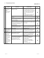
[Design Precautions]
WARNING
When controlling a running programmable controller (modifying data) by connecting peripheral
devices to the CPU module or connecting a personal computer to the intelligent function
module, configure an interlocking circuit in a sequence program so that the safety of the overall
system is always maintained. Also, before performing other control operations (program
modifications and operation status modifications (status control)) on the running programmable
controller, be sure to read the manual carefully and thoroughly confirm the safety.
Especially in the above mentioned control operations that are performed from an external device
to a remote programmable controller, any problems on the programmable controller side may
not be dealt with promptly due to a data communication error. In addition to configuring an
interlocking circuit in a sequence program, determine how the system handles data
communication errors, etc. between the devices and the programmable controller CPU.
Do not write any data in the "system area (Use prohibited)" of the buffer memory of the
intelligent function module. Also, do not output (turn on) the "use prohibited" signal, which is one
of the output signals from the programmable controller CPU to the intelligent function module. If
data is written to the "system area (Use prohibited)" or the "use prohibited" signal is output, there
is a risk that the programmable controller system may malfunction.
A-1
A-1
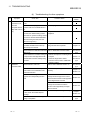
CAUTION
Do not bundle the control wires and the communication cables with the main circuit and the
power wires, and do not install them close to each other. They should be installed at least 100
mm (3.94 in.) away from each other. Failure to do so may generate noise that may cause
malfunctions.
[Installation Precautions]
CAUTION
Be sure to shut off all phases of the external power supply used by the system before mounting
or removing the module.
Failure to do so may damage the module.
Use the programmable controller in the operating environment that meets the general
specifications described in the user's manual of the CPU Module to use. Using the
programmable controller in any other operating environments may cause electric shocks, fires
or malfunctions, or may damage or degrade the module.
While pressing the installation lever located at the bottom of the module, insert the module fixing
projection into the fixing hole in the base unit to mount the module.
Incorrect module mounting may cause a malfunction, failure, or drop of the module.
In an environment of frequent vibrations, secure the module with the screw.
Be sure to tighten the screws using the specified torque. If the screws are loose, it may cause
the module to short-circuit, malfunction or fall off. If the screws are tightened excessively, it may
damage the screws and cause the module to short-circuit, malfunction or fall off.
Do not directly touch any conductive part or electronic component of the module.
Doing so may cause a malfunction or failure of the module.
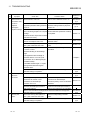
[Wiring Precautions]
WARNING
Be sure to shut off all phases of the external power supply before installation or wiring.
Failure to do so may result in an electric shock or damage to the product.
Use crimp-contact, pressure-displacement or soldering to wire the connectors for external
connections properly using the manufacturer-specified tools.
If the connection is incomplete, it may cause the module to short circuit, catch fire, or
malfunction.
A-2
A-2
CAUTION
Securely connect the connector to the module.
Make sure to place the communication and power cables to be connected to the module in a
duct or fasten them using a clamp. If the cables are not placed in a duct or fastened with a
clamp, their positions may be unstable or moved, and they may be pulled inadvertently.
This may damage the module and the cables or cause the module to malfunction because of
faulty cable connections.
Wire the module correctly after confirming the type of the connected interface. If the cable is
connected to a different interface or wired incorrectly, it may cause a fire or breakdown.
When disconnecting the communication and power cables from the module, do not pull the
cables by hand. When disconnecting a cable with a connector, hold the connector to the module
by hand and pull it out to remove the cable. If the cable is pulled while being connected to the
module, it may damage the module and/or cable or make cable contact improper, causing a
malfunction.
Be careful not to let any foreign matter such as wire chips get inside the module.
They may cause fire, as well as breakdowns and malfunctions of the module.
A protective sheet is pasted on the upper part of the module in order to prevent foreign matter
such as wire chips to get inside the module while wiring.
Do not remove this protective sheet during wiring work. However, be sure to remove the
protective sheet before operating the module to allow heat radiation during operation.
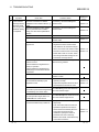
[Setup and Maintenance Precautions]
WARNING
Do not touch the terminals while the power is on. Doing so may cause electric shocks or
malfunctions.
Before cleaning the module or retightening the module mounting screws, make sure to shut off
all phases of the external power supply used by the system. Failure to do so may cause the
module to electric shocks, breakdown or malfunction. If the screws are loose, it may cause the
module to short-circuit, malfunction or fall off. If the screws are tightened excessively, it may
damage the screws and cause the module to short circuit, malfunction or fall off.
A-3
A-3
CAUTION
Before performing online operations (especially, program modification, forced output or
operating status change) by connecting a peripheral device to a running CPU, read the manual
carefully and ensure the safety. Incorrect operation will cause mechanical damage or accidents.
Never disassemble or modify the module. This may cause breakdowns, malfunctions, injuries or
fire.
When using a wireless communication device such as a cellular phone, keep a distance of 25cm
(9.85 inch) or more from the programmable controller in all directions. Failure to do so can
cause a malfunction.
Before mounting/dismounting the module, be sure to shut off all phases of the external power
supply used by the system. Failure to do so may cause module failure or malfunctions.
Do not install/remove the module to/from the base unit more than 50 times after the first use of
the product. (IEC 61131-2 compliant)
Failure to do so may cause malfunction.
Always make sure to touch the grounded metal to discharge the electricity charged in the body,
etc., before touching the module.
Failure to do so may cause a failure or malfunctions of the module.
[Operating Precautions]
CAUTION
Please read the manual carefully and confirm the safety thoroughly before performing control
operations (especially, modifications of data, programs and operation status (status control)) of
the programmable controller that is running.
Incorrect modifications of data, programs and operating status may cause system malfunctions,
damages to the machines, or accidents.
[Disposal Precautions]
CAUTION
Dispose of this product as an industrial waste.
A-4
A-4
CONDITIONS OF USE FOR THE PRODUCT
(1) Mitsubishi programmable controller ("the PRODUCT") shall be used in conditions;
i) where any problem, fault or failure occurring in the PRODUCT, if any, shall not lead to any major or
serious accident; and
ii) where the backup and fail-safe function are systematically or automatically provided outside of the
PRODUCT for the case of any problem, fault or failure occurring in the PRODUCT.
(2) The PRODUCT has been designed and manufactured for the purpose of being used in general
industries.
MITSUBISHI SHALL HAVE NO RESPONSIBILITY OR LIABILITY (INCLUDING, BUT NOT LIMITED
TO ANY AND ALL RESPONSIBILITY OR LIABILITY BASED ON CONTRACT, WARRANTY, TORT,
PRODUCT LIABILITY) FOR ANY INJURY OR DEATH TO PERSONS OR LOSS OR DAMAGE TO
PROPERTY CAUSED BY the PRODUCT THAT ARE OPERATED OR USED IN APPLICATION NOT
INTENDED OR EXCLUDED BY INSTRUCTIONS, PRECAUTIONS, OR WARNING CONTAINED IN
MITSUBISHI'S USER, INSTRUCTION AND/OR SAFETY MANUALS, TECHNICAL BULLETINS AND
GUIDELINES FOR the PRODUCT.
("Prohibited Application")
Prohibited Applications include, but not limited to, the use of the PRODUCT in;
Nuclear Power Plants and any other power plants operated by Power companies, and/or any other
cases in which the public could be affected if any problem or fault occurs in the PRODUCT.
Railway companies or Public service purposes, and/or any other cases in which establishment of a
special quality assurance system is required by the Purchaser or End User.
Aircraft or Aerospace, Medical applications, Train equipment, transport equipment such as Elevator
and Escalator, Incineration and Fuel devices, Vehicles, Manned transportation, Equipment for
Recreation and Amusement, and Safety devices, handling of Nuclear or Hazardous Materials or
Chemicals, Mining and Drilling, and/or other applications where there is a significant risk of injury to
the public or property.
Notwithstanding the above, restrictions Mitsubishi may in its sole discretion, authorize use of the
PRODUCT in one or more of the Prohibited Applications, provided that the usage of the PRODUCT is
limited only for the specific applications agreed to by Mitsubishi and provided further that no special
quality assurance or fail-safe, redundant or other safety features which exceed the general
specifications of the PRODUCTs are required. For details, please contact the Mitsubishi
representative in your region.
A-5
A-5
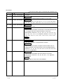
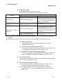
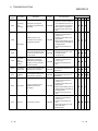
REVISIONS
The manual number is given on the bottom left of the back cover.
Print Date
Manual Number
Revision
Jan., 2004 SH (NA) -080446ENG-A First Edition
Mar., 2004 SH (NA) -080446ENG-B Modifications
Section 7.2.2, 8.3.2, 8.4, 8.6, 8.7, 9.2.2, 11.1, 11.4, 11.5
Nov., 2005 SH (NA) -080446ENG-C Modifications
Section 4.3.10, 5.2.1, 6.1, 6.2, 6.6, 7.1, 7.3.1, 7.4.1 to 7.4.5, 8.2.2,
8.3.1, 8.3.3, 8.7.2, 9.1, 10.2, 10.3, 11.1, 11.2, 11.3.2, 11.3.3, 11.4
Feb., 2006 SH (NA) -080446ENG-D Modifications
Section 2.1, 2.4, 10.1
Jan., 2008 SH (NA) -080446ENG-E Modifications
SAFETY PRECAUTIONS, Conformation to the EMC Directive and
Low Voltage Instruction, About the Generic Terms and
Abbreviations, Section 2.1, 2.5, 3.1, 3.2.1, 5.1, 5.2.1, 5.5, 6.1, 6.4,
6.6, 7.2.2, 7.4.1, 7.4.2, 7.4.4, Chapter 8, Section 9.1.3, 9.3.1, 9.3.2,
9.3.3, 10.2, 10.3, 11.1, 11.2, 11.3.1, 11.3.3, 11.4.1, 11.4.2, 11.5.1
Addition
Section 2.4
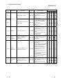
May, 2008 SH (NA) -080446ENG-F Change of a term
"PLC" was changed to "programmable controller".
Modifications
SAFETY PRECAUTIONS, Compliance with the EMC and Low
Voltage Directives, About the Generic Terms and Abbreviations,
Section 2.1, 3.1, 6.1, 6.6, 7.4.2, 8.2.1, 8.3.1, 8.3.3, 8.6, 10.2, 10.3,
11.2, 11.3.3, Appendix 3
Nov., 2010 SH (NA)-080446ENG-G Modifications
SAFETY PRECAUTIONS, About the Generic Terms and
Abbreviations, Section 2.1, 2.5, 6.3, 6.6, 8.2.1, 11.2, Appendix,
WARRANTY
Addition
CONDITIONS OF USE FOR THE PRODUCT
A-6
A-6
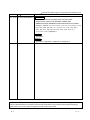
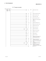
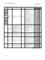
The manual number is given on the bottom left of the back cover.
Print Date
Manual Number
Revision
Oct., 2014 SH (NA)-080446ENG-H Modifications
COMPLIANCE WITH THE EMC AND LOW VOLTAGE
DIRECTIVES, ABOUT THE GENERIC TERMS AND
ABBREVIATIONS, MEANINGS AND DEFINITIONS OF TERMS,
Chapter 1, Section 2.1, 2.2, 2.4, 2.5, 3.1, 3.3.1, 4.3, 4.3.12, 5.1, 6.2,
6.3, 6.5.1, 6.5.2, 6.6, 6.6.1, 7.1, 7.2.2, 7.3.1, 7.4.2, 7.4.4, 8.2.1,
8.2.2, 8.6, 9.1.1, 9.2.2, 9.2.3, 9.3.2, 9.3.3, 10.2, 10.3, 11.1,
11.2,11.3.2, 11.3.3, Appendix 1
Addition
Appendix 2
Change
Appendix 2→Appendix 3, Appendix 3→Appendix 4
Japanese Manual Version SH(NA)-080445-J
This manual confers no industrial property rights or any rights of any other kind, nor does it confer any patent
licenses. Mitsubishi Electric Corporation cannot be held responsible for any problems involving industrial property
rights which may occur as a result of using the contents noted in this manual.
2004 MITSUBISHI ELECTRIC CORPORATION
A-7
A-7
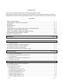
INTRODUCTION
Thank you for purchasing the MELSEC-Q series programmable controller.
Before using the equipment, please read this manual carefully to develop full familiarity with the functions
and performance of the Q series programmable controller you have purchased, so as to ensure correct use.
CONTENTS
SAFETY PRECAUTIONS ..............................................................................................................................A- 1
CONDITIONS OF USE FOR THE PRODUCT .............................................................................................A- 5
REVISIONS ....................................................................................................................................................A- 6
INTRODUCTION ............................................................................................................................................A- 8
CONTENTS ....................................................................................................................................................A- 8
COMPLIANCE WITH THE EMC AND LOW VOLTAGE DIRECTIVES .......................................................A-12
THE MANUAL'S USAGE AND STRUCTURE ..............................................................................................A-12
ABOUT THE GENERIC TERMS AND ABBREVIATIONS ...........................................................................A-14
MEANINGS AND DEFINITIONS OF TERMS...............................................................................................A-15
PRODUCT CONFIGURATION......................................................................................................................A-15
1 OVERVIEW
1- 1 to 1- 5
1.1 Features ................................................................................................................................................... 1- 1
2 SYSTEM CONFIGURATION
2- 1 to 2- 9
2.1 Applicable Systems .................................................................................................................................. 22.2 Devices Necessary for Network Configuration ....................................................................................... 22.3 System Configuration and Access Range .............................................................................................. 22.4 Precautions for System Configuration ..................................................................................................... 22.5 Checking Function Version and Software Version ................................................................................. 23 SPECIFICATIONS
3- 1 to 3-10
3.1 Performance Specifications ..................................................................................................................... 33.2 I/O Signals for Programmable Controller CPU ....................................................................................... 33.2.1 I/O signal list ...................................................................................................................................... 33.3 Applications and Assignment of Buffer Memory ..................................................................................... 33.3.1 Buffer memory list ............................................................................................................................. 34 MODBUS
R
STANDARD FUNCTIONS
1
3
4
6
7
2
3
3
5
5
4- 1 to 4-20
4.1 MODBUS Standard Function Support List ........................................................................................... 4- 1
4.2 Frame Specifications ............................................................................................................................... 4- 3
4.3 PDU Formats by Functions...................................................................................................................... 4- 4
4.3.1 Read coils (FC: 01) ........................................................................................................................... 4- 6
4.3.2 Read discrete inputs (FC: 02) ........................................................................................................... 4- 7
4.3.3 Read holding registers (FC: 03)........................................................................................................ 4- 8
4.3.4 Read input registers (FC: 04) ........................................................................................................... 4- 9
4.3.5 Write single coil (FC: 05) ................................................................................................................... 4-10
4.3.6 Write single register (FC: 06) ............................................................................................................ 4-11
4.3.7 Write multiple coils (FC: 15) .............................................................................................................. 4-12
R
A-8
A-8
4.3.8 Write multiple registers (FC: 16) ....................................................................................................... 4-14
4.3.9 Read file record (FC: 20) (SC: 06) .................................................................................................... 4-15
4.3.10 Write file record (FC: 21) (SC: 06) .................................................................................................. 4-17
4.3.11 Mask write register (FC: 22) ........................................................................................................... 4-19
4.3.12 Read/Write multiple registers (FC: 23) ........................................................................................... 4-20
5 FUNCTIONS
5- 1 to 5-15
5.1 Function List ............................................................................................................................................. 5- 1
5.2 Master Function ....................................................................................................................................... 5- 3
5.2.1 Automatic communication function ................................................................................................... 5- 3
5.2.2 Dedicated instructions ....................................................................................................................... 5- 9
5.3 Slave Function.......................................................................................................................................... 5-10
5.3.1 Automatic response function ............................................................................................................ 5-10
®
5.3.2 MODBUS device assignment function ........................................................................................... 5-11
5.4 KeepAlive Function .................................................................................................................................. 5-12
5.5 Router Relay Function ............................................................................................................................. 5-14
5.6 GX Developer Connection Function ........................................................................................................ 5-15
6 PRE-OPERATIONAL PROCEDURES AND SETTING
6- 1 to 6-21
6.1 Handling Precautions ............................................................................................................................... 6- 1
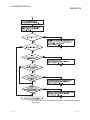
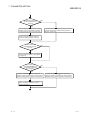
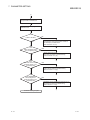
6.2 Pre-Operational Procedures and Setting ................................................................................................ 6- 2
6.3 Part Names .............................................................................................................................................. 6- 4
6.4 Connection to Ethernet ............................................................................................................................ 6- 6
6.5 Unit Tests ................................................................................................................................................. 6- 8
6.5.1 Hardware test .................................................................................................................................... 6- 8
6.5.2 Self-loopback test .............................................................................................................................. 6- 9
6.6 Intelligent Function Module Switch Setting ............................................................................................. 6-10
6.6.1 Communication starting conditions depending on basic parameter/MODBUS device assignment
parameter starting method setting .................................................................................................... 6-16
R
7 PARAMETER SETTING
7- 1 to 7-33
7.1 Parameter Settings and Setting Procedure ............................................................................................ 7- 1
7.2 Basic Parameters ..................................................................................................................................... 7- 6
7.2.1 Basic parameters details ................................................................................................................... 7- 6
7.2.2 TCP/UDP/IP setting .......................................................................................................................... 7- 8
7.2.3 GX Developer connection information setting .................................................................................. 7-16
®
7.2.4 MODBUS /TCP setting ..................................................................................................................... 7-17
7.3 Automatic Communication Parameters................................................................................................... 7-19
7.3.1 Automatic communication parameters details ................................................................................. 7-19
®
7.4 MODBUS Device Assignment Parameters ........................................................................................... 7-23
®
7.4.1 MODBUS device sizes .................................................................................................................... 7-25
®
7.4.2 MODBUS device assignment parameters details .......................................................................... 7-26
7.4.3 Default assignment parameters ........................................................................................................ 7-29
®
7.4.4 MODBUS extended file register assignment .................................................................................. 7-31
7.4.5 QJ71MT91 buffer memory assignment ............................................................................................ 7-32
A-9
A-9
8 UTILITY PACKAGE (GX Configurator-MB)
8- 1 to 8-36
8.1 Functions of the Utility Package .............................................................................................................. 8- 1
8.2 Installing and Uninstalling the Utility Package ........................................................................................ 8- 2
8.2.1 Handling precautions ........................................................................................................................ 8- 2
8.2.2 Operating environment...................................................................................................................... 8- 4
8.3 Utility Package Operation ........................................................................................................................ 8- 6
8.3.1 Common utility package operations ................................................................................................. 8- 6
8.3.2 Operation overview ........................................................................................................................... 8- 9
8.3.3 Starting the Intelligent function module utility ................................................................................... 8-11
8.4 Initial Setting ............................................................................................................................................. 8-13
8.5 Auto Refresh Setting ................................................................................................................................ 8-15
8.6 Monitor/Test ............................................................................................................................................. 8-17
8.6.1 X/Y Monitor/test ................................................................................................................................. 8-21
®
8.6.2 Basic/MODBUS device assignment parameter status .................................................................. 8-23
8.6.3 Automatic communication status ...................................................................................................... 8-24
8.6.4 Error log ............................................................................................................................................. 8-26
8.6.5 Communication status....................................................................................................................... 8-27
8.6.6 PING test ........................................................................................................................................... 8-29
8.7 Parameter Setting Using GX Configurator-MB ....................................................................................... 8-30
8.7.1 Basic parameters .............................................................................................................................. 8-30
8.7.2 Automatic communication parameters ............................................................................................. 8-33
®
8.7.3 MODBUS device assignment parameters...................................................................................... 8-35
9 PROGRAMMING
9- 1 to 9-49
9.1 Parameter Setting .................................................................................................................................... 9- 1
9.1.1 Basic parameter setting .................................................................................................................... 9- 1
9.1.2 Automatic communication parameter setting ................................................................................... 9- 4
®
9.1.3 MODBUS device assignment parameter setting ........................................................................... 9- 7
9.2 Program Example for Normal System Configuration.............................................................................. 9-11
9.2.1 System configuration and program conditions ................................................................................. 9-11
9.2.2 Program using utility package........................................................................................................... 9-18
9.2.3 Program without using utility package .............................................................................................. 9-22
9.3 Program Example for Use in MELSECNET/H Remote I/O Network ..................................................... 9-29
9.3.1 System configuration and program conditions ................................................................................. 9-29
9.3.2 Program using utility package........................................................................................................... 9-35
9.3.3 Program without using utility package .............................................................................................. 9-39
10 DEDICATED INSTRUCTIONS
10- 1 to 10-18
10.1 Dedicated Instruction List and Available Devices ............................................................................... 10- 1
10.2 Z(P).MBRW .......................................................................................................................................... 10- 2
10.3 Z(P).MBREQ ........................................................................................................................................ 10-11
11 TROUBLESHOOTING
11- 1 to 11-48
11.1 Troubleshooting ................................................................................................................................... 11- 1
11.2 Confirming QJ71MT91 Status ............................................................................................................. 11-12
A - 10
A - 10
11.3 Error Codes .......................................................................................................................................... 11-15
11.3.1 Error code storage areas .............................................................................................................. 11-15
11.3.2 Exception code list ........................................................................................................................ 11-21
11.3.3 Error code list ................................................................................................................................ 11-23
11.4 Turning Off the COM.ERR. LED ......................................................................................................... 11-40
11.4.1 From GX Configurator-MB ............................................................................................................ 11-40
11.4.2 Program example for use of sequence program ......................................................................... 11-43
11.5 Conducting PING Test to Check QJ71MT91 Connection .................................................................. 11-44
11.5.1 From GX Configurator-MB ............................................................................................................ 11-45
11.5.2 Program example for use of sequence program ......................................................................... 11-49
APPENDICES
App- 1 to App- 8
Appendix 1 External Dimensions ................................................................................................................App- 1
Appendix 2 Function Upgrade of the QJ71MT91 ......................................................................................App- 2
Appendix 3 Processing Time ......................................................................................................................App- 2
Appendix 4 GX Developer Connection Setup Example ............................................................................App- 6
INDEX
A - 11
Index- 1 to Index- 4
A - 11
COMPLIANCE WITH THE EMC AND LOW VOLTAGE DIRECTIVES
(1) Method of ensuring compliance
To ensure that Mitsubishi programmable controllers maintain EMC and Low
Voltage Directives when incorporated into other machinery or equipment,
certain measures may be necessary. Please refer to one of the following
manuals.
QCPU User's Manual (Hardware Design, Maintenance and Inspection)
Safety Guidelines
(This manual is included with the CPU module or base unit.)
The CE mark on the side of the programmable controller indicates compliance
with EMC and Low Voltage Directives.
(2) Additional measures
To ensure that this product maintains EMC and Low Voltage Directives, please
refer to one of the manuals listed under (1).
THE MANUAL'S USAGE AND STRUCTURE
How to use this manual
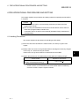
This manual describes the pre-operation procedure, functions, etc. by use of the
MODBUS /TCP interface module (QJ71MT91) on a purpose-by-purpose basis.
Refer to the corresponding section when you need to know the following:
R
(1) Features (Chapter 1)
Chapter 1 describes the features of the QJ71MT91.
(2) System configuration (Chapter 2)
(a) Section 2.1 describes the applicable programmable controller CPUs and
compatible software packages.
(b) Section 2.2 describes the devices necessary to configure a network.
(c) Section 2.3 describes the system configurations that use the QJ71MT91 and
the accessible range.
(3) Performance and specifications (Chapter 3)
(a) Section 3.1 provides the performance specifications of the QJ71MT91.
(b) Section 3.2 and 3.3 give the I/O signal and buffer memory lists of the
QJ71MT91.
(4) MODBUS standard functions supported by the QJ71MT91
(Chapter 4)
R
(a) Section 4.1 gives a list of MODBUS standard functions supported by the
QJ71MT91.
(b) Section 4.2 and 4.3 provide the frame specifications of the MODBUS
standard functions supported by the QJ71MT91.
R
R
A - 12
A - 12
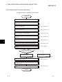
(5) Usable functions (Chapter 5)
Chapter 5 describes the functions of the QJ71MT91.
(6) Settings and procedures necessary to operate the system (Chapter
6)
Chapter 6 describes the pre-operation settings and procedures.
(7) Parameter setting of the QJ71MT91 (Chapter 7)
Chapter 7 describes the parameter setting procedures and parameter details.
(8) Parameter setting from the utility package (Chapter 8)
Chapter 8 describes the utility package operation method.
(9) Parameter setting from sequence programs (Chapter 9)
Chapter 9 describes the I/O signals used for parameter setting, the I/O signal
timing charts, and program examples.
(10) Reading/Writing, etc. of MODBUS device data with sequence
programs (Chapter 10)
R
Chapter 10 describes the dedicated instructions designed to perform read/write,
etc. of MODBUS device data with sequence programs.
R
(11) Error codes and corresponding corrective actions (Chapter 11)
(a) Section 11.1 describes the troubleshooting.
(b) Section 11.2 describes how to check the module condition.
(c) Section 11.3 describes the error code storage location and details.
(d) Section 11.4 describes how to turn OFF the COM.ERR. LED.
(e) Section 11.5 describes the PING test.
About the notation of the numerical values used in this manual
Among the numerical values used in this manual, "H" is placed to the right of the
units place for hexadecimal notation.
(Example)
A - 13
10 ..... Decimal
10H ... Hexadecimal
A - 13
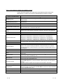
ABOUT THE GENERIC TERMS AND ABBREVIATIONS
Unless otherwise specified, this manual uses the following generic terms and
abbreviations to explain the QJ71MT91 MODBUS /TCP interface module.
R
Description
Generic Term/Abbreviation
QJ71MT91
The abbreviation for the QJ71MT91 MODBUS /TCP interface module
A generic term for the protocol designed to use MODBUS protocol messages on a
TCP/IP network
A generic term for the protocol designed to use MODBUS protocol messages on a
serial interface
The abbreviation for the function code
The abbreviation for the sub code
R
R
MODBUS /TCP
R
R
MODBUS serial protocol
R
FC
SC
Programmable controller CPU
Basic model QCPU
High Performance model
QCPU
Process CPU
Redundant CPU
Universal model CPU
GX Developer
GX Works2
Ethernet module
Ethernet Address
MELSECNET/H
Master
Slave
A generic term for the Basic model QCPU, High Performance model QCPU, Process
CPU, Redundant CPU, Universal model QCPU
A generic term for the Q00JCPU, Q00CPU and Q01CPU
A generic term for the Q02CPU, Q02HCPU, Q06HCPU, Q12HCPU and Q25HCPU
A generic term for the Q02PHCPU, Q06PHCPU, Q12PHCPU and Q25PHCPU
A generic term for the Q12PRHCPU and Q25PRHCPU
A generic term for the Q00UJCPU, Q00UCPU, Q01UCPU, Q02UCPU, Q03UDCPU,
Q03UDVCPU, Q03UDECPU, Q04UDHCPU, Q04UDVCPU, Q04UDEHCPU,
Q06UDHCPU, Q06UDVCPU, Q06UDEHCPU, Q10UDHCPU, Q10UDEHCPU,
Q13UDHCPU, Q13UDVCPU, Q13UDEHCPU, Q20UDHCPU, Q20UDEHCPU,
Q26UDHCPU, Q26UDVCPU, Q26UDEHCPU, Q50UDEHCPU, and Q100UDEHCPU
The product name of the software package for the MELSEC programmable controllers
The QJ71E71-100 Ethernet interface module
A machine-specific address that is also referred to as the MAC (Media Access Control)
address. This is used to identify the addresses of external devices over a network.
The Ethernet address of the QJ71MT91 can be verified on the MAC ADD column of
the rating plate.
The MELSECNET/H network system
The side from which a request is sent to execute a function
The side where the execution request from the master is processed and its execution
result is sent
The function that allows communication with the MODBUS /TCP compatible slave
device as the master of MODBUS /TCP
The function that allows communication with the MODBUS /TCP compatible master
device as the slave of MODBUS /TCP
The message used to give a function execution request to the slave.
In the MODBUS protocol, a function execution request is given from the master to
the slave.
A function execution request cannot be given from the slave to the master.
The message with which the slave returns a function execution result to the master
A generic term for the communication targets connected for data communication.
(personal computer, other QJ71MT91 MODBUS /TCP interface module, MODBUS
protocol compatible device, etc.)
The IBM PC/AT or compatible DOS/V-based personal computer
The abbreviation for Z.MBRW or ZP.MBRW
The abbreviation for Z.MBREQ or ZP.MBREQ
R
Master function
R
R
Slave function
R
R
Request message
Response message
Target device
Personal computer
MBRW
MBREQ
A - 14
R
R
A - 14
Description
Generic Term/Abbreviation
A generic term for Microsoft Windows 7 Starter operating system,
Microsoft Windows 7 Home Premium operating system, Microsoft Windows 7
Professional operating system, Microsoft Windows 7 Ultimate operating system,
and Microsoft Windows 7 Enterprise operating system
Note that the 32-bit version is specified as "32-bit Windows 7", and the 64-bit version
is specified as "64-bit Windows 7".
A generic term for Microsoft Windows Vista Home Basic operating system,
Microsoft Windows Vista Home Premium operating system, Microsoft Windows
Vista Business operating system, Microsoft Windows Vista Ultimate operating system,
and Microsoft Windows Vista Enterprise operating system
A generic term for Microsoft Windows XP Professional operating system, and
Microsoft Windows XP Home Edition operating system
R
R
R
R
R
R
Windows 7
R
R
R
R
R
R
R
R
R
Windows Vista
R
R
R
R
R
R
R
R
R
Windows XP
R
R
R
R
R
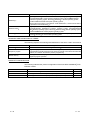
MEANINGS AND DEFINITIONS OF TERMS
The following explains the meanings and definitions of the terms used in this manual.
Term
MODBUS device
R
Sequence program
Device memory
Meaning/Definition
Device used for communication using the MODBUS protocol
Programming system devised to make a contact type sequence compatible with the
programmable controller language as-is. Draw two vertical control buses and describe
contacts, etc. between the buses to perform programming.
Memory provided for the programmable controller CPU to record the data handled in
sequence program operation
R
PRODUCT CONFIGURATION
The following indicates the product configuration of the QJ71MT91 MODBUS /TCP
interface module.
R
Item name
Model
QJ71MT91
QJ71MT91 MODBUS /TCP interface module
SW1D5C-QMBU-E
SW1D5C-QMBU-EA
GX Configurator-MB Version 1 (1-license product)
GX Configurator-MB Version 1 (Multiple-license product)
A - 15
Quantity
1
R
(CD-ROM)
(CD-ROM)
1
1
A - 15
1 OVERVIEW
MELSEC-Q
1 OVERVIEW
1
This manual explains the specifications, functions, programming, troubleshooting, etc.
of the MELSEC-Q series QJ71MT91 MODBUS /TCP interface module (hereafter
abbreviated to the QJ71MT91).
The QJ71MT91 is used to connect the MELSEC-Q series programmable controller to
a MODBUS /TCP network.
R
R
1.1 Features
(1) Supporting master function of MODBUS /TCP communication
R
The QJ71MT91 supports the master function of MODBUS /TCP
communication, which is an open network system for factory automation, and it is
compatible with various MODBUS /TCP slave devices (hereafter abbreviated to
the slaves) of other manufactures.
The master function supports the following two functions.
R
R
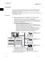
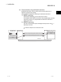
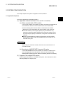
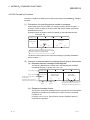
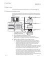
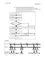
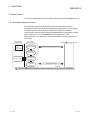
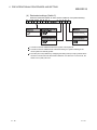
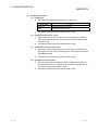
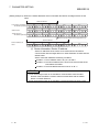
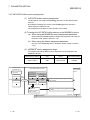
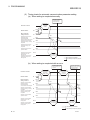
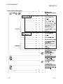
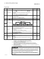
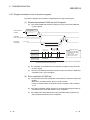
(a) Automatic communication function
By setting the automatic communication parameters, MODBUS device
data can be automatically read from or written to the slaves at the specified
intervals using the QJ71MT91 buffer memory. ( 1)
Data can be transferred between the QJ71MT91 buffer memory and
programmable controller CPU device memory by making the auto refresh
setting with the utility package (GX Configurator-MB) or accessing a
intelligent function module device with a sequence program.
R
MODBUS R /TCP slave device
(Third party remote I/O, etc.)
Ethernet
Holding register
Programmable
controller CPU
QJ71MT91(Master function)
R
MODBUS /TCP slave device
(Third party sensor, etc.)
Buffer memory
Device memory
100ms read
250ms read
Auto refresh
Holding register
1000ms read
100ms write
MODBUS R /TCP slave device
(Third party programmable
controller)
Holding register
MODBUS R device read/write request
messages are issued to the slave
repeatedly at specified intervals.
1: The MODBUS
R
device indicates the device area of the slave where data can be read/written in
response to a request from the master.
1-1
1-1
1 OVERVIEW
MELSEC-Q
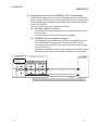
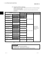
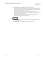
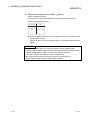
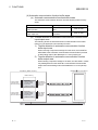
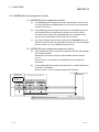
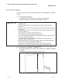
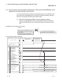
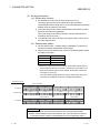
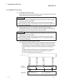
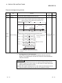
(b) Communication using dedicated instruction
Dedicated instructions can be used to make communication from a
sequence program at any timing.
The QJ71MT91 supports the following two dedicated instructions.
1) MBRW instruction
Reads/writes MODBUS device data from/to a slave.
This enables slave data to be read out to the programmable controller
CPU device memory or programmable controller CPU data to be
written to the slave.
R
2) MBREQ instruction
Can issue user-desired request message format (function code 1 +
data unit) to a slave.
1: Refer to Chapter 4 for the function code.
Programmable
controller CPU
MODBUS R /TCP slave device
QJ71MT91
(Master function)
Holding register
Command
[Z.MBRW
]
Request message (holding register 400500 read request)
Device memory
Response message (holding register 400500 = 1234H)
400500
1234H
1234H
Ethernet
1-2
1-2
1
1 OVERVIEW
MELSEC-Q
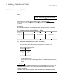
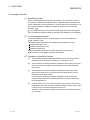
(2) Supporting slave function of MODBUS /TCP communication
R
The QJ71MT91 supports the slave function of MODBUS /TCP communication,
which is an open network system for factory automation, and it is compatible with
various MODBUS /TCP master devices (hereafter abbreviated to the masters)
of other manufacturers.
The slave function supports the following two functions.
R
R
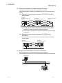
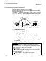
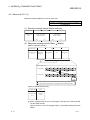
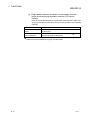
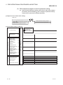
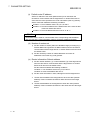
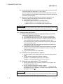
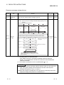
(a) Automatic response function
The QJ71MT91 can automatically respond to a request message received
from the master.
A sequence program for the slave function is not needed.
(b) MODBUS device assignment function
R
Using MODBUS device assignment parameters, the MODBUS devices
are correlated with the programmable controller CPU device memory.
This enables direct access from the master to the programmable controller
CPU device memory.
Supporting the MODBUS devices of large capacity, the QJ71MT91 allows
all device memories of the programmable controller CPU to be assigned.
R
R
R
Programmable
controller CPU
Sequence program
not needed
D300
MODBUS R /TCP
master device
QJ71MT91(Slave function)
MODBUS R
device assignment parameters
Device memory
Device memory
D299
400499
1234H
D300
400500
D301
400501
MODBUS R device
Request message (holding register 400500 read request)
Response message (holding register 400500 = 1234H)
Ethernet
1-3
1-3
1 OVERVIEW
MELSEC-Q
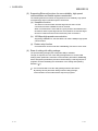
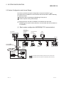
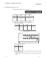
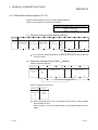
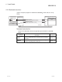
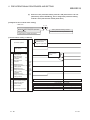
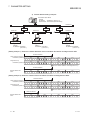
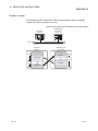
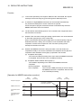
(3) Concurrent operation of master and slave functions
The master and slave functions can be operated concurrently.
This enables flexible construction of a MODBUS /TCP communication-based
system.
R
(a) Example of communication between QJ71MT91 and third
party devices
Third party
programmable controller
Ethernet
Master
Third party remote I/O
(Slave)
QJ71MT91
(Master/slave function)
(Master)
Request
message
Request
message
Response
message
1)
Response
message
Slave
Master
2)
Slave
1) In response to a request message from the master, the QJ71MT91
operates as a slave and returns a response message.
2) The QJ71MT91 operates as a master, and issues a request message
to the slave.
(b) Example of communication between QJ71MT91 and
QJ71MT91
The both functions can be operated bi-directionally between QJ71MT91
and QJ71MT91.
QJ71MT91
(Master/slave function)
QJ71MT91
(Master/slave function)
Request
message
Response
message
Ethernet
(4) Support of GX Developer connection via Ethernet
GX Developer can be connected to Ethernet via the QJ71MT91.
This enables the maintenance of the programmable controller CPU via Ethernet.
GX Developer
Ethernet
QJ71MT91
1-4
1-4
1 OVERVIEW
MELSEC-Q
(5) Supporting Ethernet functions for more reliability, high speed
communication and flexible system construction
The following Ethernet functions are supported for more reliability, high speed
communication and more flexible system construction.
(a) KeepAlive function
The status of communication with the target device where a TCP
connection has been established can be checked.
When communication is not made for a given period of time between the
QJ71MT91 and the open target device, the QJ71MT91 checks the target
device for existence and cuts off unnecessary TCP connections.
(b) 100 Mbps high-speed communication
Supporting 100BASE-TX, the QJ71MT91 can make 100Mbps high-speed
communication.
(c) Router relay function
Communication can be made with a MODBUS /TCP device via a router.
R
(6) Ease of setting with utility package
The optional utility package (GX Configurator-MB) is available.
Though not required, the use of the utility package allows on-screen initial
settings (basic parameters, automatic communication parameters, MODBUS
device assignment parameters) and auto refresh settings, reducing sequence
programs and also facilitating the confirmation of the setting and operating
statuses. ( 1)
R
1: It is recommended to use the utility package with the QJ71MT91.
By making various parameter settings with the utility package,
communication can be made without sequence programs.
1-5
1-5
2 SYSTEM CONFIGURATION
MELSEC-Q
2 SYSTEM CONFIGURATION
This chapter explains the system configuration of the QJ71MT91.
2.1 Applicable Systems
2
This section describes the applicable systems.
(1) Applicable modules and base units, and No. of modules
(a) When mounted with a CPU module
For the CPU modules, the number of modules, and base units applicable to
the QJ71MT91, refer to the user's manual for the CPU module used.
Note the following when the QJ71MT91 is used with a CPU module.
Depending on the combination with other modules or the number of
mounted modules, power supply capacity may be insufficient. Pay
attention to the power supply capacity before mounting modules, and if
the power supply capacity is insufficient, change the combination of the
modules.
Mount a module within the number of I/O points for the CPU module.
If the number of slots is within the available range, the module can be
mounted on any slot.
REMARK
When using a C Controller module, refer to the user's manual for the C
Controller module.
(b) Mounting to a MELSECNET/H remote I/O station
For the MELSECNET/H remote I/O station, the number of modules, and
base units applicable to the QJ71MT91, refer to the Q Corresponding
MELSECNET/H Network System Reference Manual (Remote I/O network).
(2) Support of the multiple CPU system
When using the QJ71MT91 in a multiple CPU system, refer to the QCPU User's
Manual (Multiple CPU System) first.
2-1
2-1
2 SYSTEM CONFIGURATION
MELSEC-Q
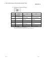
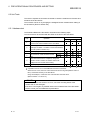
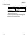
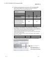
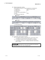
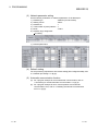
(3) Supported software packages
Relation between the system containing the QJ71MT91 and software package is
shown in the following table.
GX Developer or GX Works2 is required to start up the system that uses the
QJ71MT91.
Software version
2
GX Developer 1
Single CPU system
Version 7 or later
Multiple CPU system
Version 8 or later
Q02/Q02H/Q06H/
Single CPU system
Version 4 or later
Q12H/Q25HCPU
Multiple CPU system
Version 6 or later
Q00J/Q00/Q01CPU
Q02PH/Q06PHCPU
Q12PH/Q25PHCPU
Q12PRH/Q25PRHCPU
Q00UJ/Q00U/Q01UCPU
Single CPU system
Multiple CPU system
Single CPU system
Multiple CPU system
Redundant system
Single CPU system
Multiple CPU system
Q02U/Q03UD/Q04UDH/ Single CPU system
Q06UDHCPU
Q10UDH/Q20UDHCPU
Q13UDH/Q26UDHCPU
Q03UDE/Q04UDEH/
Q06UDEH/Q13UDEH/
Q26UDEHCPU
Multiple CPU system
Single CPU system
Multiple CPU system
Single CPU system
Multiple CPU system
Single CPU system
GX Configurator-MB
GX Works2
Version 8.68W or later Version 1.00A or later
Version 7.10L or later
Version 8.45X or later
Version 8.76E or later
Refer to the GX
Works2 Version 1
Version 8.48A or later
Operating Manual
(Common).
Version 8.76E or later
Version 8.62Q or later
Version 1.08J or later
Version 8.68W or later
Multiple CPU system
Q10UDEH/
Single CPU system
Q20UDEHCPU
Multiple CPU system
CPU modules other than
Single CPU system
the above
Multiple CPU system
When mounted to MELSECNET/H remote I/O
station
Version 8.76E or later
Not supported
Version 6.01B or later
Not supported
Version 1.00A or later
1: For the accessible range of GX Developer, refer to Section 2.3.
POINT
When using GX Works2, refer to the following:
GX Works2 Version 1 Operating Manual (Common)
GX Works2 Version 1 Operating Manual (Intelligent Function Module)
2-2
2-2
2 SYSTEM CONFIGURATION
MELSEC-Q
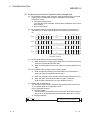
2.2 Devices Necessary for Network Configuration
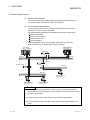
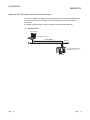
This section explains the devices that configure a network.
Please note that the network must be installed by qualified networking specialists to
take sufficient safety measures.
The 10BASE-T or 100BASE-TX can be used to connect the QJ71MT91 to a network.
The QJ71MT91 will distinguish between 10BASE-T and 100BASE-TX, and between
the full duplex and half duplex communication mode according to the hub type.
However, for connection with the hub that does not have the auto negotiation function,
set the half duplex communication mode on the hub side.
Hub (*1)
Twisted pair cable
Target device
QJ71MT91
MODBUS®/TCP slave device
MODBUS®/TCP master device
*1: For the number of cascade connection stages, refer to the Section 3.1.
Use the devices that comply with the IEEE802.3 100BASE-TX/10BASE-T Standard.
(1) Hub and other equipment
(a) Shielded twisted pair cable
1) For 100BASE-TX
Shielded twisted pair cable (STP cable), Category 5
2) For 10BASE-T
Unshielded twisted pair cable (UTP cable), Category 3 (4, 5)
A straight cable can be used.
(We do not guarantee proper operation if a crossing cable is used for the
100BASE-TX/10BASE-T connection between the QJ71MT91 and the
target device.)
(b) RJ45 jack
(c) Hub for 100Mbps/10Mbps network
POINT
In high-speed communication (100Mbps) by the 100BASE-TX connection, a
communication error may occur under the influence of high frequency noise from
devices other than the programmable controller in the installation environment.
Take the following action on the QJ71MT91 side to prevent the influence of high
frequency noise in the construction of a network system.
(1) Wiring connection
Do not install a twisted pain cable together with the main circuit and power
cables, etc.
Place the twisted pair cable in a duct.
(2) Communication system
Increase the number of communication retries if necessary.
Change the hub used for connection into a 10Mbps hub, and make
communication at a transmission speed of 10Mbps.
2-3
2-3
2 SYSTEM CONFIGURATION
MELSEC-Q
2.3 System Configuration and Access Range
This section provides the system configurations using the QJ71MT91. ( 1)
The target devices available for communication with the QJ71MT91 are the following
two kinds of devices.
Master/slave device supporting the MODBUS /TCP protocol
Personal computer running GX Developer
R
1: Ethernet devices can also be installed on the Ethernet line where the
MODBUS /TCP system exists. (However, communication with the QJ71MT91 is
not available.)
R
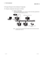
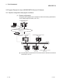
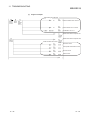
(1) Basic system configuration (MODBUS /TCP communication)
R
QJ71MT91
[Master/slave function]
Third party
programmable
controller
[Master]
User application
[Master]
HMI
[Master]
Ethernet
MODBUS R /TCP
serial gateway device
MODBUS R serial
slave device
Third party
programmable
controller
[Slave]
User application
[Slave]
Remote I/O
[Slave]
CNC
[Slave]
QJ71MT91
[Slave function]
Third party
programmable controller
MELSEC-A series
programmable controller
(AJ71UC24-S2)
Remote I/O
Accessible from QJ71MT91 (master function) to each slave
Accessible from each master to QJ71MT91 (slave function)
2-4
2-4
2 SYSTEM CONFIGURATION
MELSEC-Q
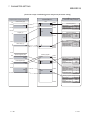
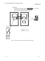
(2) GX Developer connection
(a) Accessible range of GX Developer
Refer to Appendix 3 for the GX Developer connection setup examples.
[Access path via QJ71MT91]
GX Developer
QJ71MT91
Connected
programmable
controller
MODBUS R /TCP
(b) Precautions for GX Developer connection
When the QJ71MT91 and Ethernet module exist together on the same
Ethernet, access cannot be made between the QJ71MT91 and Ethernet
module.
GX Developer
Ethernet module
QJ71MT91
Ethernet and MODBUS R /TCP mixed network
2-5
2-5
2 SYSTEM CONFIGURATION
MELSEC-Q
2.4 Precautions for System Configuration
(1) For use in a redundant system
When using the QJ71MT91 in a redundant system, refer to the QnPRHCPU
User's Manual (Redundant System).
2-6
2-6
2 SYSTEM CONFIGURATION
MELSEC-Q
2.5 Checking Function Version and Software Version
This section describes checking methods for the function version of the QJ71MT91
and the software version of GX Configurator-MB.
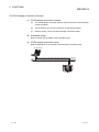
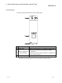
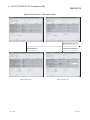
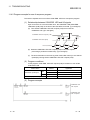
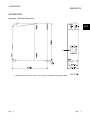
(1) Checking the function version of the QJ71MT91
The serial number and function version of the QJ71MT91 can be checked on the
rating plate, front of the module, or system monitor window in GX Developer.
(a) Checking on the rating plate
The rating plate is located on the side of the QJ71MT91.
Serial number (first 5 digits)
Function version
MAC ADD.
06011
Relevant regulation
standards
(b) Checking on the front of the module
The serial number and function version on the rating plate is printed on the
front (at the bottom) of the module.
Function version
Serial No.
2-7
2-7
2 SYSTEM CONFIGURATION
MELSEC-Q
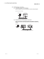
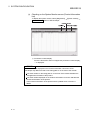
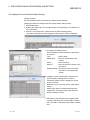
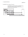
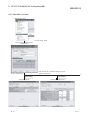
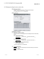
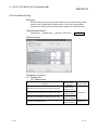
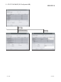
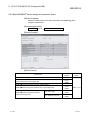
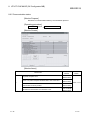
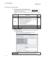
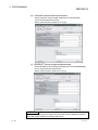
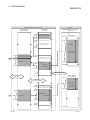
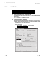
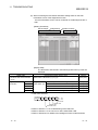
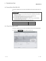
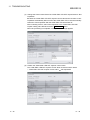
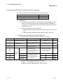
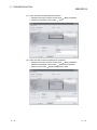
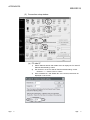
(c) Checking on the System Monitor screen (Product Information
List)
To display the system monitor, select [Diagnostics]
Product Inf. List button of GX Developer.
[System monitor]
1) Production number display
Since the QJ71MT91 does not support the production number display,
“-” is displayed.
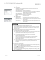
POINT
The serial number displayed on the Product Information List screen of GX
Developer may differ from that on the rating plate or on the front of the module.
The serial number on the rating plate or on the front of the module indicates the
management information of the product.
The serial number displayed on the Product Information List screen indicates the
functional information of the product.
The functional information of the product will be updated when a function is
added.
2-8
2-8
2 SYSTEM CONFIGURATION
MELSEC-Q
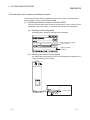
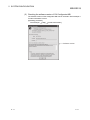
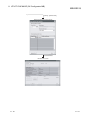
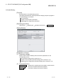
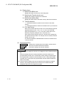
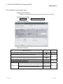
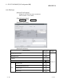
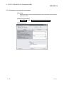
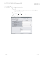
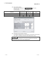
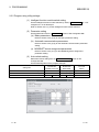
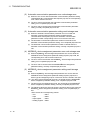
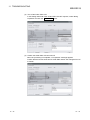
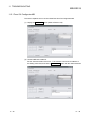
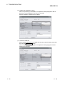
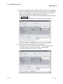
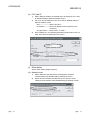
(2) Checking the software version of GX Configurator-MB
The software version of GX Configurator-MB can be checked in GX Developer’s
"Product information" screen.
[Operating procedure]
GX Developer [Help] [Product information]
Software version
2-9
2-9
3 SPECIFICATIONS
MELSEC-Q
3 SPECIFICATIONS
This chapter explains the QJ71MT91's performance specifications, I/O signals for
programmable controller CPU, and buffer memory.
For general specifications, refer to QCPU User's Manual (Hardware Design,
Maintenance and Inspection).
3
3-1
3-1
3 SPECIFICATIONS
MELSEC-Q
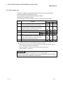
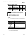
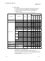
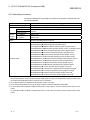
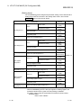
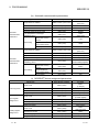
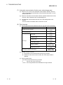
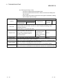
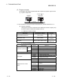
3.1 Performance Specifications
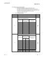
This section provides the performance specifications of the QJ71MT91.
Specifications
Item
Transmission
specifications
Data transmission rate
Transmission method
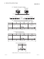
Maximum node-to-node distance
Maximum segment length 1
Number of cascade connection stages
Maximum number of connections 3
Number of routers that can be set
Cable
Master
function
Connector applicable for external wiring
Number of slaves 4
Automatic
Function (for send)
communicaInput area size
tion function
Output area size
Number of instructions that
can be executed
concurrently 5
Dedicated
Function (for send)
instruction
Input area size
Output area size
Automatic
response
function
Slave function
Function (for receive)
R
MODBUS
device size
Coil
Input
Input register
Holding register
Extended file register
No. of simultaneously acceptable request
messages
GX Developer
Number of simultaneously connectable GX
connection
Developers
function
Number of occupied I/O points
5VDC internal current consumption
External dimensions
Weight
10BASE-T
10Mbps
100BASE-TX
100Mbps
Base band
200m (656.16ft.)
100m (328.08ft.)
Max. 4 stages 2
Max. 2 stages 2
64 connections
1 default router + any 8 routers
Cable compliant with the
Cable compliant with the
IEEE802.3 100BASE-TX
IEEE802.3 10BASE-T
Standard (shielded
Standard (unshielded
twisted pair cable (STP
twisted pair cable (UTP
cable), Category 5)
cable), Category 3 (4, 5))
RJ45
64 slaves
7 functions
4k words
4k words
Reference
Section
3
Section 2.2
Chapter 4
Section
3.3.1
Up to 8 instructions
MBRW instruction: 9 functions
MBREQ instruction: 19 functions
Max. 253 bytes per instruction
Max. 253 bytes per instruction
Chapter 4
Chapter 4
12 functions
Chapter 4
64k points
64k points
64k points
64k points
Section
7.4.1
Max. 4086k points
64
Max. 8 GX Developers
32 points
0.52A
27.4 (1.08 in.) (W)
98 (3.86 in.) (H)
90 (3.54 in.) (D) [mm]
0.11kg
Section
7.2.3
Appendix 1
1: Length between a hub and a node.
2: This is the maximum number of cascade connection stages when a repeater hub is used.
For the maximum number of cascade connection stages, contact to the manufacturer for the
switching hub used.
3: Indicates the number of TCP connections that can be established simultaneously.
4: Indicates the maximum number of slaves that can be communication targets.
5: Indicates the maximum number of dedicated instructions that can be started simultaneously
from a sequence program.
3-2
3-2
3 SPECIFICATIONS
MELSEC-Q
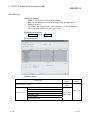
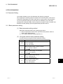
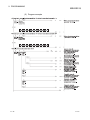
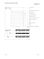
3.2 I/O Signals for Programmable Controller CPU
This section explains the I/O signals of the QJ71MT91 for the programmable controller
CPU.
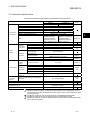
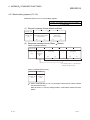
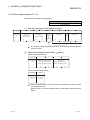
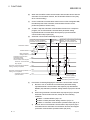
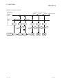
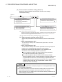
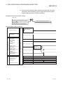
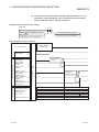
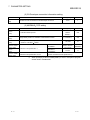
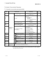
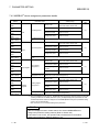
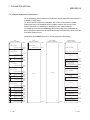
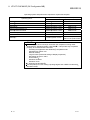
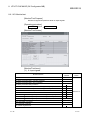
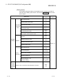
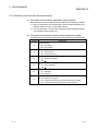
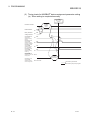
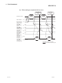
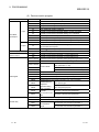
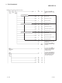
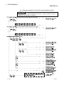
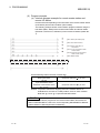
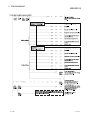
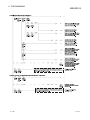
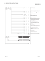
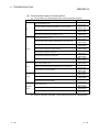
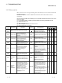
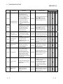
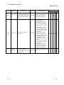
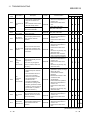
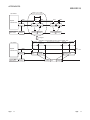
3.2.1 I/O signal list
The following table shows the I/O signals of the QJ71MT91.
The following I/O signal assignment is based on the case where the start I/O No. of the
QJ71MT91 is "0000" (installed to slot 0 of the main base unit).
Device X represents an input signal from the QJ71MT91 to the programmable
controller CPU.
Device Y shows an output signal from the programmable controller CPU to the
QJ71MT91.
Refer to the corresponding reference sections for details.
Signal Direction QJ71MT91
Programmable controller CPU
Device
Reference
Signal name
No.
section
Module READY 1
Section
ON : Accessible
X0
11.1
OFF: Inaccessible
Basic parameter setting, normally
completed
X1
ON : Normally completed
OFF:
Basic parameter setting, error completed
Section
X2
ON : Error completed
9.1.1
OFF:
Basic parameter setting existence
X3
ON : Parameters set
OFF: No parameters set
X4
X5
X6
X7
Automatic communication parameter
setting, normally completed
ON : Normally completed
OFF:
Automatic communication parameter
setting, error completed
ON : Error completed
OFF:
Automatic communication operation status
ON : Operating
OFF: Stopped
Automatic communication error status
ON : Error occurred
OFF: No error
X8
MODBUS device assignment parameter
setting, normally completed
ON : Normally completed
OFF:
X9
MODBUS device assignment parameter
setting, error completed
ON : Error completed
OFF:
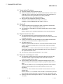
Signal Direction Programmable controller CPU
Device
Signal name
No.
Y0
Use prohibited
Y1
Basic parameter setting request
ON : Being requested
OFF: Not requested
Use prohibited
Y3
Y4
Automatic communication parameter
setting request/automatic communication
start request
ON : Parameter setting being
requested/start being requested
OFF: No parameter setting requested/no
start requested
Y5
Use prohibited
Y6
Automatic communication stop request
ON : Being requested
OFF: Not requested
Y7
Use prohibited
Y8
MODBUS device assignment parameter
setting request
ON : Being requested
OFF: Not requested
Y9
Use prohibited
R
R
Section
9.1.1
Y2
Section
5.2.1,
9.1.2
Section
5.2.1
QJ71MT91
Reference
section
Section
5.2.1,
9.1.2
Section
5.2.1
R
Section
9.1.3
Section
9.1.3
1: Turns ON when the QJ71MT91 is ready after the programmable controller is turned ON
from OFF or after the programmable controller CPU is reset.
(Continued on next page)
3-3
3-3
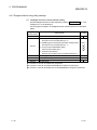
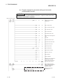
3 SPECIFICATIONS
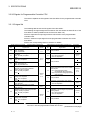
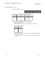
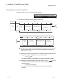
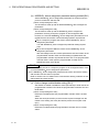
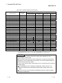
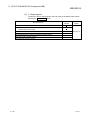
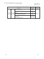
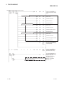
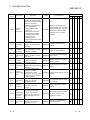
Signal Direction QJ71MT91
Device
No.
MELSEC-Q
Programmable controller CPU
Signal name
MODBUS device assignment
parameter setting existence
ON : Parameters set
OFF: No parameters set
Signal Direction Programmable controller CPU
Reference
section
Device
No.
Section
9.1.3
YA
Signal name
QJ71MT91
Reference
section
R
XA
XB
YB
XC
YC
XD
YD
XE
YE
XF
YF
X10
Y10
X11
Y11
X12
Y12
Use prohibited
Use prohibited
X13
Y13
X14
Y14
X15
Y15
X16
Y16
X17
Y17
X18
Y18
X19
Y19
X1A
Y1A
X1B
COM.ERR.LED status
ON : Lit
OFF: Not lit
Section
11.4.2
X1C
PING test completed
ON : PING test completed
OFF:
Section
11.5.2
X1D
Y1B
COM. ERR. LED OFF request
ON : Being requested
OFF: Not requested
Section
11.4.2
Y1C
PING test execution request
ON : PING test execution being
requested
OFF: PING test execution not request
Section
11.5.2
Y1D
Use prohibited
X1E
X1F
Y1E
Watch dog timer error
ON : Module error occurred
OFF: Module operating normally
Section
11.1
Use prohibited
Y1F
Important
Among the I/O signals for the programmable controller CPU, do not output (turn
ON) the "Use prohibited" signals.
Doing so may cause the programmable controller system malfunction.
3-4
3-4
3 SPECIFICATIONS
MELSEC-Q
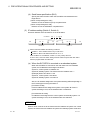
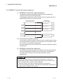
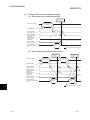
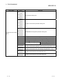
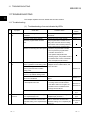
3.3 Applications and Assignment of Buffer Memory
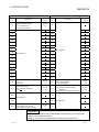
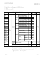
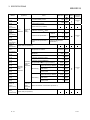
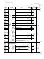
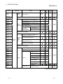
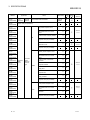
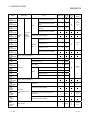
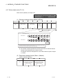
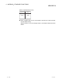
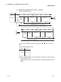
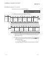
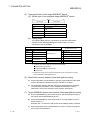
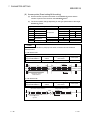
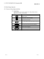
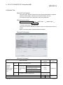
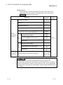
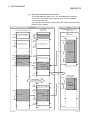
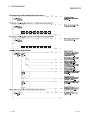
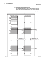
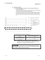
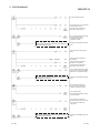
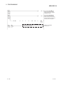
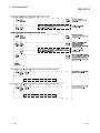
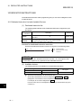
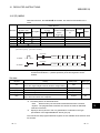
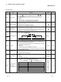
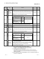
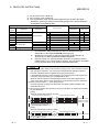
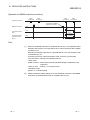
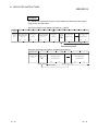
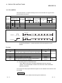
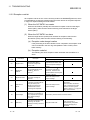
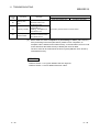
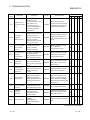
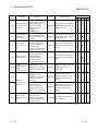
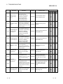
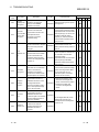
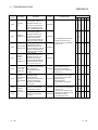
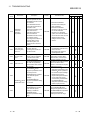
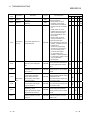
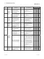
3.3.1 Buffer memory list
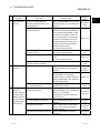
A buffer memory list is given below.
Address
Application
Name
0000H
(0)
0001H
(1)
0002H
(2)
0003H
(3)
0004H
(4)
TCP/UDP/
IP
monitoring
timer
0005H
(5)
0006H
(6)
0007H
(7)
0008H
(8)
0009H
(9)
000AH
(10)
000BH to
000CH
(11 to 12)
000DH to
000EH
(13 to 14)
000FH
(15)
0010H to
0011H
(16 to 17)
0012H to
0013H
(18 to 19)
0014H to
002FH
(20 to 47)
Initial Value
TCP ULP timer value
Set time = set value
500ms
TCP zero window timer value
Set time = set value
500ms
TCP resend timer value
Set time = set value
500ms
TCP end timer value
Set time = set value
500ms
IP reassembly timer value
Set time = set value
500ms
Split reception monitoring timer
value
500ms
Set time = set value
3CH(60)
R/W
14H(20)
R/W
14H(20)
R/W
28H(40)
R/W
AH(10)
R/W
3CH(60)
R/W
1H
R/W
4B0H
(1200)
R/W
14H(20)
R/W
KeepAlive resend count
3H
R/W
Router relay function
0H
R/W
Subnet mask pattern
FFFFFF00H
R/W
Default router IP address
0H
R/W
Number of routers set
0H
R/W
Subnet
address
0H
R/W
Router IP
address
0H
R/W
KeepAlive
KeepAlive
TCP/UDP/
IP setting
Basic
parameter
Routing
information
Read/
Write
( 1)
KeepAlive start timer value
Set time = set value
500ms
KeepAlive interval timer value
Set time = set value
500ms
Router
information 1
Router
information 2 to 8
0030H
(48)
GX
Developer
connection
information
setting
0031H to
010FH
(49 to 271)
System area (use prohibited)
Initial
Setting
( 2)
Reference
Section
Section
7.2
(Same as router information 1)
Number of TCP connections for GX
Developer connection
1H
R/W
Section
7.2
(Continued on next page)
1: Indicates whether the address is readable and/or writable from/to a sequence program.
R: Readable
W: Writable
2: Indicates whether setting on GX Configurator-MB is enabled or disabled.
: Setting enabled
3-5
: Setting disabled
3-5
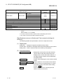
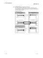
3 SPECIFICATIONS
Address
0110H
(272)
0111H
(273)
0112H to
0113H
(274 to 275)
0114H
(276)
0115H to
0116H
(277 to 278)
0117H
(279)
0118H to
01D4H
(280 to 468)
01D5H to
01FFH
(469 to 511)
0200H to
0201H
(512 to 513)
0202H
(514)
0203H
(515)
0204H
(516)
0205H
(517)
0206H
(518)
0207H
(519)
0208H
(520)
0209H
(521)
020AH
(522)
020BH
(523)
020CH to
04FFH
(524 to 1279)
0500H to
08FFH
(1280 to 2303)
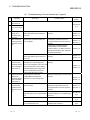
MELSEC-Q
Application
Name
Initial Value
Read
/Write
( 1)
Local slave station port No.
502
R/W
Target slave port No. for automatic
communication function
502
R/W
AH(10)
R/W
IP address
0H
R/W
Number of
connections
0H
Initial
Setting
( 2)
Reference
Section
Section
7.2
System area (use prohibited)
Basic
parameter
MODBUS
/TCP
setting
R
CPU response monitoring timer value
500ms
Set time = set value
Preferred node specification 1
Preferred node specification 2
to 64
R/W
Section
7.2
(Same as preferred node
specification 1)
System area (use prohibited)
00000000
R/W
255H
R/W
0
R/W
0
R/W
0000H
R/W
0000H
R/W
Target MODBUS device
head number
0
R/W
Access points
0
R/W
0000H
R/W
Target MODBUS device
head number
0
R/W
Access points
0
R/W
Target station IP address
Module ID
Repeat interval timer value
10ms
Set time = set value
Response check timer value
500ms
Set time = set value
Automatic
communication
parameter
Automatic
communication
parameter
1
Target MODBUS device type specification
R
Head buffer memory address
R
Read setting
Head buffer memory address
Section
7.3
R
Write setting
Automatic
communication
parameter
2 to 64
(Same as automatic communication parameter 1)
System area (use prohibited)
(Continued on next page)
3-6
3-6
3 SPECIFICATIONS
Address
0900H
(2304)
0901H
(2305)
0902H
(2306)
0903H
(2307)
0904H to
093FH
(2308 to 2367)
0940H
(2368)
0941H
(2369)
0942H
(2370)
0943H
(2371)
0944H to
097FH
(2372 to 2431)
0980H
(2432)
0981H
(2433)
0982H
(2434)
0983H
(2435)
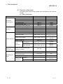
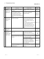
Application
Coil
assignment
1
Coil
assignment
2 to 16
Input
assignment
1
MODBUS
device
assignment
parameter
R
Input
assignment
2 to 16
Input
register
assignment
1
Input
register
assignment
2 to 16
0984H to
09BFH
(2436 to 2495)
09C0H
(2496)
09C1H
(2497)
09C2H
(2498)
09C3H
(2499)
Holding
register
assignment
1
09C4H to
09FFH
(2500 to 2559)
Holding
register
assignment
2 to 16
0A00H to
0BFFH
(2560 to 3071)
0C00H
(3072)
0C01H
(3073)
0C02H
(3074)
0C03H
(3075)
0C04H
(3076)
MELSEC-Q
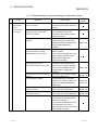
Name
Initial Value
Read/
Write
( 1)
Device code
0H
R/W
Head device number
0H
R/W
Head coil number
0H
R/W
Assignment points
0H
R/W
Device code
0H
R/W
Head device number
0H
R/W
Head input number
0H
R/W
Assignment points
0H
R/W
Device code
0H
R/W
Head device number
0H
R/W
Head input register number
0H
R/W
Assignment points
0H
R/W
Device code
0H
R/W
Head device number
0H
R/W
Head holding register number
0H
R/W
Assignment points
0H
R/W
Initial
Setting
( 2)
Reference
Section
(Same as coil assignment 1)
(Same as input assignment 1)
Section
7.4
(Same as input register assignment 1)
(Same as holding register assignment 1)
System area (use prohibited)
R
Switch 1: Operation mode setting status
Setting
status
Intelligent
function
module
switch
setting
status
Switch 2: Communication condition setting
status
Switch 3: Local station IP address setting
status
Switch 4: Local station IP address setting
status
Switch 5: Redundant setting status
Intelligent
function
module
switch
status
R
R
R
Section
6.6
Section
11.2
R
(Continued on next page)
3-7
3-7
3 SPECIFICATIONS
Address
Application
0C05H
(3077)
Module
status
0C06H to
0C0FH
(3078 to 3087)
0C10H
(3088)
0C11H
(3089)
0C12H
(3090)
0C13H
(3091)
0C14H
(3092)
0C15H
(3093)
0C16H to
0C1FH
(3094 to 3103)
0C20H to
0C23H
(3104 to 3107)
0C24H to
0C27H
(3108 to 3111)
0C28H to
0C67H
(3112 to 3175)
0C68H to
0CA7H
(3176 to 3239)
0CA8H to
0CFDH
(3240 to 3325)
0CFEH
(3326)
0CFFH
(3327)
0D00H
(3328)
0D01H
(3329)
0D02H
(3330)
0D03H
(3331)
0D04H to
0D05H
(3332 to 3333)
0D06H
(3334)
0D07H
(3335)
0D08H to
0DFFH
(3336 to 3583)
MELSEC-Q
Name
Initial Value
LED ON
status
LED ON status
Read/
Write
( 1)
R
Initial
Setting
( 2)
Reference
Section
Section
6.3
Section
11.2
System area (use prohibited)
0H
R
0H
R
0H
R
0H
R
Error, device type
0H
R
Error, assigned group
No.
0H
R
0H
R
Section
11.3.1
0H
R
Section
11.3.1
Number of errors occurred
0H
R
Error log write pointer
0H
R
Detailed error code
0H
R
Exception code
0H
R
Function code
0H
R
Local station port No.
0H
R
Target IP address
0H
R
Target device port No.
0H
R
Basic parameter error code storage area
Parameter
error
information
Automatic communication parameter error
code storage area
Automatic communication parameter setting
result storage area
MODBUS device assignment parameter
error code storage area
R
MODBUS device
assignment
parameter setting
result storage area
R
Section
11.3.1
System area (use prohibited)
Automatic communication operation status
storage area (parameters 1 to 64)
Operating
status
Communication
status
monitor
area
System area (use prohibited)
Automatic communication error code storage
area (parameters 1 to 64)
System area (use prohibited)
System area (use prohibited)
Error log
Error log 1
Section
11.3.1
System area (use
prohibited)
Error log 2 to 32
(Same as error log 1)
Section
11.3.1
(Continued on next page)
3-8
3-8
3 SPECIFICATIONS
Address
0E00H to
0E02H
(3584 to 3586)
0E03H to
0E0FH
(3587 to 3599)
0E10H to
0E11H
(3600 to 3601)
0E12H to
0E13H
(3602 to 3603)
0E14H to
0E15H
(3604 to 3605)
0E16H to
0E29H
(3606 to 3625)
0E2AH to
0E2BH
(3626 to 3627)
0E2CH to
0E2FH
(3628 to 3631)
0E30H to
0E31H
(3632 to 3633)
0E32H to
0E33H
(3634 to 3635)
0E34H to
0E35H
(3636 to 3637)
0E36H to
0E37H
(3638 to 3639)
0E38H to
0E39H
(3640 to 3641)
0E3AH to
0E3BH
(3642 to 3643)
0E3CH to
0E3DH
(3644 to 3645)
0E3EH to
0E4FH
(3646 to 3663)
0E50H to
0E51H
(3664 to 3665)
0E52H to
0E53H
(3666 to 3667)
0E54H to
0E55H
(3668 to 3669)
0E56H to
0E6FH
(3670 to 3695)
MELSEC-Q
Application
H/W
information
Ethernet
address
Name
Local station Ethernet address
Initial Value
Ethernet
address
Read
/Write
( 1)
Initial
Setting
( 2)
Reference
Section
R
System area (use prohibited)
IP packet reception count
0H
R
Count of IP packet reception
discarded due to sum check
error
0H
R
Total number of sent IP packets
0H
R
0H
R
ICMP packet reception count
0H
R
Count of ICMP packet reception
discarded due to sum check
error
0H
R
Total number of sent ICMP
packets
0H
R
Total number of ICMP echo
request received
0H
R
Total number of ICMP echo
reply sent
0H
R
Total number of ICMP echo
request sent
0H
R
Total number of ICMP echo
reply received
0H
R
TCP packet reception count
0H
R
Count of TCP packet reception
discarded due to sum check
error
0H
R
Total number of sent TCP
packets
0H
R
Section
11.3.1
IP
System area (use prohibited)
Simultaneous transmission error
detection count
Section
11.3.1
System area (use prohibited)
Communication
status
Communication
status by
protocol
type
Section
11.3.1
ICMP
System area (use prohibited)
TCP
Section
11.3.1
System area (use prohibited)
(Continued on next page)
3-9
3-9
3 SPECIFICATIONS
Address
0E70H to
0E71H
(3696 to 3697)
0E72H to
0E73H
(3698 to 3699)
0E74H to
0E75H
(3700 to 3701)
0E76H to
0E79H
(3702 to 3705)
0E7AH to
0E83H
(3706 to 3715)
0E84H to
0E85H
(3716 to 3717)
0E86H to
0E87H
(3718 to 3719)
0E88H to
0E89H
(3720 to 3721)
0E8AH to
0E8FH
(3722 to 3727)
0E90H to
0FDFH
(3728 to 4063)
0FE0H
(4064)
0FE1H
(4065)
0FE2H to
0FE3H
(4066 to 4067)
0FE4H
(4068)
0FE5H
(4069)
0FE6H
(4070)
0FE7H
(4071)
0FE8H to
0FFFH
(4072 to 4095)
1000H to
1FFFH
(4096 to 8191)
2000H to
2FFFH
(8192 to
12287)
3000H to
3FFFH
(12288 to
16383)
4000H to
4FFFH
(16384 to
20479)
5000H to
5FFFH
(20480 to
24575)
3 - 10
MELSEC-Q
Application
Name
Initial Value
Read/
Write
( 1)
Initial
Setting
( 2)
Reference
Section
UDP packet reception count
0H
R
Count of UDP packet reception
discarded due to sum check
error
0H
R
Total number of sent UDP
packets
0H
R
Framing error count
0H
R
Overflow count
0H
R
CRC error count
0H
R
Communication time check
2H
R/W
Transmission count
4H
R/W
IP address
0H
R/W
Execution result
0H
R
Total packet transmission count
0H
R
Success count
0H
R
Failure count
0H
R
Automatic communication function buffer
input area
0H
R
Section
5.2.1
0H
R/W
Section
5.2.1
0H
R/W
Section
7.4.5
UDP
Section
11.3.1
System area (use prohibited)
Communication
status
Communication
status by
protocol
type
System area (use prohibited)
Receive
error
Section
11.3
System area (use prohibited)
System area (use prohibited)
PING test
Result
Section
11.5
System area (use prohibited)
System area (use prohibited)
Automatic
communication function
buffer
Automatic communication function buffer
output area
System area (use prohibited)
User free area
3 - 10
4 MODBUS STANDARD FUNCTIONS
R
MELSEC-Q
4 MODBUS STANDARD FUNCTIONS
R
This chapter explains the MODBUS
R
standard functions supported by the QJ71MT91.
4.1 MODBUS Standard Function Support List
R
(1) MODBUS standard function support list
R
The following table indicates a list of the MODBUS
supported by the QJ71MT91.
Function Code
(Sub Code)
4
Function
R
standard functions
Processing
Reference
01
Read coils
Reads the statuses (ON/OFF) of one or more coils.
02
Read discrete inputs
Reads the statuses (ON/OFF) of one or more inputs.
Section 4.3.2
03
Read holding registers
Reads the values of one or more holding registers.
Section 4.3.3
04
Read input registers
Reads the values of one or more input registers.
Section 4.3.4
05
Write single coil
Writes a value (ON/OFF) to one coil.
Section 4.3.5
Section 4.3.6
Write single register
Writes a value to one holding register.
07
06
1
2
Read exception status
Reads error statuses indicated by eight coils.
08
1
2
Diagnostics
Executes various diagnostics.
The diagnostics results are returned to the master.
11
1
2
Get communications event
counter
Gets the communication event counter.
1
2
12
Section 4.3.1
Get communications event log
Gets the communication event log.
15
Write multiple coils
Writes values (ON/OFF) to multiple coils.
Section 4.3.7
16
Write multiple registers
Writes values to multiple holding registers.
Section 4.3.8
17
Report slave I.D
Reads the type, status, etc. of the slave device to the master.
20(6)
1
2
Read file record
Reads the values of one or more extended file registers.
Section 4.3.9
21(6)
Write file record
Writes values to one or more extended file registers.
Section 4.3.10
22
Mask write register
Masks the value stored in one holding register with AND or
OR, and writes a value.
Section 4.3.11
23
Read/write multiple registers
Reads and writes values from and to multiple holding
registers.
Section 4.3.12
24
1
Read FIFO queue
Reads values from the holding registers in FIFO queue
structure.
43
1
Read device identification
Reads the module identification information of the slave.
1: The QJ71MT91 slave function does not support this function.
However, it can be issued from the master (QJ71MT91) by use of the MBREQ instruction.
2: The function codes 07, 08, 11, 12 and 17 are the functions dedicated to the MODBUS
R
serial
protocol.
4-1
4-1
4 MODBUS STANDARD FUNCTIONS
R
MELSEC-Q
(2) Standard function support list by master and slave functions
The following table indicates a standard function support list classified by the
master and slave functions of the QJ71MT91.
Master Function
Function Code
(Sub Code)
Automatic
communication
function
Function
3
MBRW instruction
4
MBREQ
instruction 4
Slave Function
01
Read coils
5
02
Read discrete inputs
5
03
Read holding registers
5
04
Read input registers
5
05
Write single coil
5
06
Write single register
5
07
1
2
Read exception status
08
1
2
Diagnostics
11
1
2
Get communications event
counter
1
2
Get communications event log
12
4
15
Write multiple coils
5
16
Write multiple registers
5
17
1
2
Report slave I.D
20(6)
Read file record
6
21(6)
Write file record
6
22
Mask write register
5
23
Read/write multiple registers
5
24
1
Read FIFO queue
43
1
Read device identification
: Supported
:Not supported
1: The QJ71MT91 slave function does not support this function.
However, it can be issued from the master (QJ71MT91) by use of the MBREQ instruction.
2: The function codes 07, 08, 11, 12 and 17 are the functions dedicated to the MODBUS
R
serial
protocol.
3: For details of the function codes for the master function, refer to the explanation of the
corresponding function.
4: The dedicated instructions are unavailable for the QJ71MT91 mounted on a MELSECNET/H
remote I/O station.
5: This function has a limit in the slave function when the QJ71MT91 is mounted on a
MELSECNET/H remote I/O station.
An exception response will result if a device unsupported by the MELSECNET/H remote I/O
station is assigned as a MODBUS
R
device and an access request is made from the master
station.
In this case, an error code will be stored into the error log of the QJ71MT91, and an exception
code will be returned to the master.
6: This function is not supported when the QJ71MT91 is mounted on a MELSECNET/H remote I/O
station.
4-2
4-2
4 MODBUS STANDARD FUNCTIONS
R
MELSEC-Q
4.2 Frame Specifications
The frame specifications of MODBUS /TCP are indicated below.
R
Ethernet
header
Ethernet frame
IP header TCP header
FCS
(Error check)
Application data
MODBUS R /TCP ADU
(MODBUS R /TCP application data unit)
PDU
(Protocol data unit)
MBAP header
(MODBUS R application header)
Transaction Protocol ID Message
ID
length
Module ID
Data
Function code
(Message length)
Area Name
Area Size
Transaction ID
2 bytes
Protocol ID
2 bytes
Description
Used by the master for matching of the response
message from the slave.
Indicates the protocol of the PDU (protocol data
MBAP header
(MODBUS
R
Stores 0 in the case of MODBUS /TCP.
R
application
header)
unit).
Stores the message size in byte unit.
Message length
2 bytes
The message length after this field is stored. (See
the above figure.)
Module ID
1 byte
Function code
1 byte
PDU
(Protocol data unit)
Used to specify the slave connected to the other
line, e.g. MODBUS
R
serial protocol.
The master specifies the processing to be performed
for the slave.
[When master sends request message to slave]
Data
1 to 252 bytes
Stores the requested processing.
[When slave sends response message to master]
Stores the result of processing execution.
4-3
4-3
4 MODBUS STANDARD FUNCTIONS
R
MELSEC-Q
4.3 PDU Formats by Functions
This section explains the PDU (protocol data unit) formats of the MODBUS
functions.
R
standard
(1) Precautions for specifying device number in message
When specifying a device number in a message, specify "(device number) - 1".
However, it does not apply to the file number and device number specified for
Read/Write file record.
(Example) When the status of input 32 (100032) is read with Read discrete
inputs (FC: 02)
Function code
Function code
Data
Head input number
Read points
001FH
0001H
02H
(H)
(L)
(H)
(L)
Specify 31 (001FH) for the head input number
to read the input 32 (100032) status.
The device number stored in the response message is "(actually read/written
device number) - 1".
(2) Overview of request/response message format given in this section
(a) Request/response message format diagram
The following indicates the overview of the request/response message
format diagram given in Section 4.3.1 to 4.3.12.
Area name
Frame contents
[Request message format]
Setting range
Data
Function code
Function code
(01H)
Head coil number
(0000H to FFFFH)
(H)
[Response message format]
Value stored in response message
1 byte
(8 bits)
1 byte
(8 bits)
(L)
Read points
(0001H to 07D0H)
(H)
(L)
When 2 bytes comprise 1 data, the highorder byte (8 bits) are represented as
(H) and the low-order byte (8 bits) as (L).
(b) Response message format
The format of a response message issued by the slave to the master differs
depending on whether the processing in the slave has been completed
normally or not.
In Section 4.3.1 to 4.3.12, the formats for normal completion and error
completion are provided.
4-4
4-4
4 MODBUS STANDARD FUNCTIONS
R
MELSEC-Q
(3) Storage location of exception code and error code
On error completion of processing in the slave (QJ71MT91), an exception code is
sent to the master. (Refer to the "Response message format (when completed
with an error)" given in Section 4.3.1 to 4.3.12.)
The exception code is also stored into the QJ71MT91 buffer memory.
Further, to allow the cause to be identified in more detail, the error code is stored
into the QJ71MT91 buffer memory.
The exception code and error code can be confirmed in the error log area
(address: CFEH to DFF H) of the buffer memory.
REMARK
(1) Refer to Section 11.3 for the confirmation method and details of the exception
code and error code.
(2) Refer to Section 4.2 for details of the PDU (protocol data unit).
4-5
4-5
4 MODBUS STANDARD FUNCTIONS
R
MELSEC-Q
4.3.1 Read coils (FC: 01)
Reads the statuses (ON/OFF) of one or more coils.
Number of accessible devices with one message
1 to 2000 points
(1) Request message format (Master
Function code
Function code
(01H)
Slave)
Data
Head coil number
(0000H to FFFFH)
(H)
Read points
(0001H to 07D0H)
(L)
(H)
(L)
(2) Response message format (Slave
Master)
(When completed normally)
Function code
Function code
(01H)
Data
Number of
read bytes
n
Device data
1
Device data
n
(Number of read bytes n)
(Device data 1 to n)
b7
b6
b5
b4
b3
b2
b1
b0
Device data 1
Bit device storage
order
Device data n
0 : OFF
1 : ON
The read coil statuses are stored in order from low-order to high-order bits.
When the number of read points is not a multiple of 8, the excess bits turn to 0.
(When completed with an error)
Function code
Data
Function code
(81H)
Exception
code*
: When completed with an error, the exception code and error code are stored
into the buffer memory.
Refer to Section 11.3 for the storage location, confirmation method and more
details.
4-6
4-6
4 MODBUS STANDARD FUNCTIONS
R
MELSEC-Q
4.3.2 Read discrete inputs (FC: 02)
Reads the statuses (ON/OFF) of one or more inputs.
Number of accessible devices with one message
1 to 2000 points
(1) Request message format (Master
Function code
Function code
(02H)
Slave)
Data
Head input number
(0000H to FFFFH)
(H)
Read points
(0001H to 07D0H)
(L)
(H)
(L)
(2) Response message format (Slave
Master)
(When completed normally)
Function code
Function code
(02H)
Data
Number of
read bytes
n
Device data
1
Device data
n
(Number of read bytes n)
(Device data 1 to n)
b7
b6
b5
b4
b3
b2
b1
b0
Device data 1
Bit device storage
order
Device data n
0 : OFF
1 : ON
The read input statuses are stored in order from low-order to high-order bits.
When the number of read points is not a multiple of 8, the excess bits turn to 0.
(When completed with an error)
Function code
Data
Function code
(82H)
Exception
code*
: When completed with an error, the exception code and error code are stored
into the buffer memory.
Refer to Section 11.3 for the storage location, confirmation method and more
details.
4-7
4-7
4 MODBUS STANDARD FUNCTIONS
R
MELSEC-Q
4.3.3 Read holding registers (FC: 03)
Reads the values of one or more holding registers.
Number of accessible devices with one message
1 to 125 points
(1) Request message format (Master
Function code
Function code
(03H)
Slave)
Data
Head holding register number
(0000H to FFFFH)
(H)
Read points
(0001H to 007DH)
(L)
(H)
(L)
(2) Response message format (Slave
Master)
(When completed normally)
Data
Function code
Function code
(03H)
Number of
read bytes
n 2*1
Device data
1
(H)
Device data
n
(L)
(H)
(L)
(Number of read bytes n 2)
*1: For example, when n = 4, the number of
read bytes is 4 2 = 8 bytes.
(When completed with an error)
Function code
Data
Function code
(83H)
Exception
code*
2: When completed with an error, the exception code and error code are stored
into the buffer memory.
Refer to Section 11.3 for the storage location, confirmation method and more
details.
4-8
4-8
4 MODBUS STANDARD FUNCTIONS
R
MELSEC-Q
4.3.4 Read input registers (FC: 04)
Reads the values of one or more input registers.
Number of accessible devices with one message
1 to 125 points
(1) Request message format (Master
Function code
Function code
(04H)
Slave)
Data
Head input register number
(0000H to FFFFH)
(H)
Read points
(0001H to 007DH)
(L)
(H)
(L)
(2) Response message format (Slave
Master)
(When completed normally)
Data
Function code
Function code
(04H)
Number of
read bytes
n 2*1
Device data
1
(H)
Device data
n
(L)
(H)
(L)
(Number of read bytes n 2)
*1: For example, when n = 4, the number of
read bytes is 4 2 = 8 bytes.
(When completed with an error)
Function code
Data
Function code
(84H)
Exception
code*
2: When completed with an error, the exception code and error code are stored
into the buffer memory.
Refer to Section 11.3 for the storage location, confirmation method and more
details.
4-9
4-9
4 MODBUS STANDARD FUNCTIONS
R
MELSEC-Q
4.3.5 Write single coil (FC: 05)
Writes a value (ON/OFF) to one coil.
Number of accessible devices with one message
1 point
(1) Request message format (Master
Function code
Function code
(05H)
Slave)
Data
Coil number
(0000H to FFFFH)
ON/OFF specification
0000H : OFF
FF00H : ON
(H)
(L)
(H)
(2) Response message format (Slave
(L)
Master)
(When completed normally)
The slave returns the request message received from the master as it is.
(When completed with an error)
Function code
Data
Function code
(85H)
Exception
code*
: When completed with an error, the exception code and error code are stored
into the buffer memory.
Refer to Section 11.3 for the storage location, confirmation method and more
details.
4 - 10
4 - 10
4 MODBUS STANDARD FUNCTIONS
R
MELSEC-Q
4.3.6 Write single register (FC: 06)
Writes a value to one holding register.
Number of accessible devices with one message
1 point
(1) Request message format (Master
Function code
Function code
(06H)
Slave)
Data
Holding register number
(0000H to FFFFH)
(H)
(L)
Write data
(0000H to FFFFH)
(H)
(2) Response message format (Slave
(L)
Master)
(When completed normally)
The slave returns the request message received from the master as it is.
(When completed with an error)
Function code
Data
Function code
(86H)
Exception
code*
: When completed with an error, the exception code and error code are stored
into the buffer memory.
Refer to Section 11.3 for the storage location, confirmation method and more
details.
4 - 11
4 - 11
4 MODBUS STANDARD FUNCTIONS
R
MELSEC-Q
4.3.7 Write multiple coils (FC: 15)
Writes values (ON/OFF) to multiple coils.
Number of accessible devices with one message
1 to 1968 points
(1) Request message format (Master
Slave)
Data
Function code
Function code
Head coil number
Write points*
(0FH)
(0000H to FFFFH)
(0001H to 07B0H)
Number
of bytes
n*
Device data
1
Device data
n
(0001H to 00F6H)
(H)
(L)
(H)
(L)
(Number of bytes n)
(Device data 1 to n)
b7
b6
b5
b4
b3
b2
b1
b0
Device data 1
Data storage order
Device data n
0 : OFF
1 : ON
The values (ON/OFF) stored into the device data 1 to n are written to the coils in
order from low-order to high-order bits of the device data.
: The number of points specified as the write points must be matched with the
number of bits specified as the number of bytes.
For example, when the write points are 16, set the number of bytes to 2 bytes
(= 16 bits).
(2) Response message format (Slave
Master)
(When completed normally)
Function code
Function code
(0FH)
Data
Head coil number
(The value same as in the head
coil number in the request
message is stored.)
(H)
4 - 12
(L)
Write points
(The value same as in the
write points in the request
message is stored.)
(H)
(L)
4 - 12
4 MODBUS STANDARD FUNCTIONS
R
MELSEC-Q
(When completed with an error)
Function code
Data
Function code
(8FH)
Exception
code*
: When completed with an error, the exception code and error code are stored
into the buffer memory.
Refer to Section 11.3 for the storage location, confirmation method and more
details.
4 - 13
4 - 13
4 MODBUS STANDARD FUNCTIONS
R
MELSEC-Q
4.3.8 Write multiple registers (FC: 16)
Writes values to multiple holding registers.
Number of accessible devices with one message
1 to 123 points
(1) Request message format (Master
Function code
Function code
(10H)
Slave)
Data
Head holding
register number
Write points
n*1
(0000H to FFFFH)
(0001H to 007BH)
Device data
1
Number
of bytes
n 2*1
Device data
n
(0001H to 00F6H)
(H)
(L)
(H)
(L)
(H)
(L)
(H)
(L)
(Number of bytes n 2)
1: The number of points specified as the write points must be matched with the
number of bytes.
(2) Response message format (Slave
Master)
(When completed normally)
Function code
Function code
(10H)
Data
Head holding register number
(The value same as in the
request message is stored.)
(H)
(L)
Write points
(The value same as in the
request message is stored.)
(H)
(L)
(When completed with an error)
Function code
Data
Function code
(90H)
Exception
code*2
2: When completed with an error, the exception code and error code are stored
into the buffer memory.
Refer to Section 11.3 for the storage location, confirmation method and more
details.
4 - 14
4 - 14
4 MODBUS STANDARD FUNCTIONS
R
MELSEC-Q
4.3.9 Read file record (FC: 20) (SC: 06)
Reads the values of one or more extended file registers.
Number of accessible devices with one message
1 to 124 points
(1) Request message format (Master
Function code
Slave)
Data
Sub-request 1
Function code
(14H)
Number
of bytes
m 7
Reference
number
File number
Read head device number
(0000H to FFFFH)*
(0000H to 270FH)
Read points
n1
(06H)
(0001H to 007CH)
(H)
(L)
(H)
(L)
(H)
(L)
(Number of bytes m 7)
Data
Sub-request m
Reference
number
File number
Read head device number
(0000H to FFFFH)*
(0000H to 270FH)
(06H)
Read points
nm
(0001H to 007CH)
(H)
(L)
(H)
(L)
(H)
(L)
(Number of bytes m 7)
: The upper limit of the file number available for the QJ71MT91 slave function is
equal to the file register size of the mounted programmable controller CPU.
(Refer to Section 7.4.4.)
(a) Specify the number of sub-requests "m" so that the PDU (protocol data unit)
size in the request message does not exceed 253 bytes.
2 + m 7 253
If the above condition is not satisfied, the request message is discarded.
+ nm)" so
(b) Specify the total read points of all the sub-requests, "N (n1 +
that the PDU (protocol data unit) size in the request message does not
exceed 253 bytes.
2 + m 2 + N 2 253
If the above condition is not satisfied, the slave returns an exception
response.
4 - 15
4 - 15
4 MODBUS STANDARD FUNCTIONS
R
MELSEC-Q
(2) Response message format (Slave
Master)
(When completed normally)
Function code
Data
Sub-request 1
Function code
(14H)
Number of
response
data bytes
(m 2+N 2)
Number of
read bytes
(n1 2+1)
Reference
number
(06H)
Device data
1
(H)
Device data
n1
(L)
(H)
(Number of read bytes n1
(L)
2 + 1)
(Number of response data bytes m
2+N
2)
Data
Sub-request m
Number of
read bytes
(nm 2+1)
Reference
number
(06H)
Device data
1
(H)
Device data
nm
(L)
(Number of read bytes nm
(Number of response data bytes m
2+N
(H)
(L)
2 + 1)
2)
"N" in the above diagram represents the total (n1 +
data.
+ nm) of the device
(When completed with an error)
Function code
Data
Function code
Exception code*
(94H)
: When completed with an error, the exception code and error code are stored
into the buffer memory.
Refer to Section 11.3 for the storage location, confirmation method and more
details.
4 - 16
4 - 16
4 MODBUS STANDARD FUNCTIONS
R
MELSEC-Q
4.3.10 Write file record (FC: 21) (SC: 06)
Writes values to one or more extended file registers.
Number of accessible devices with one message
1 to 122 points
(1) Request message format (Master
Slave)
Data
Function code
Sub-request 1
Function code Number of
(15H)
bytes
m 7
Reference
number
(06H)
File number
(0000H to FFFFH)*
(H)
Write head
device number
(0000H to 270FH)
(H)
(L)
Write points
n1
(0001H to 007AH)
(L)
(H)
(L)
Device data
1
Device data
n1
(H)
(H)
(L)
(Number of bytes m
(L)
7)
Data
Sub-request m
Reference
number
(06H)
File number
(0000H to FFFFH)*
(H)
(L)
Write head
device number
(0000H to 270FH)
(H)
(Number of bytes m
(L)
Write points
nm
(0001H to 007AH)
(H)
(L)
Device data
1
Device data
nm
(H)
(H)
(L)
(L)
7)
: The upper limit of the file number available for the QJ71MT91 slave function is
equal to the file register size of the mounted programmable controller CPU.
(Refer to Section 7.4.4.)
(a) Specify the total write points of all the sub-requests, N (n1 +
+ nm) so
that the size of the PDU (protocol data unit) in the request message does
not exceed 253 bytes.
2 + m 7 + N 2 253
If the above condition is not satisfied, the request message is discarded.
4 - 17
4 - 17
4 MODBUS STANDARD FUNCTIONS
R
(2) Response message format (Slave
MELSEC-Q
Master)
(When completed normally)
The slave returns the request message received from the master as it is.
(When completed with an error)
Function code
Data
Function code
Exception code*
(95H)
: When completed with an error, the exception code and error code are stored
into the buffer memory.
Refer to Section 11.3 for the storage location, confirmation method and more
details.
POINT
Even if the slave (QJ71MT91) receives this function with the programmable
controller CPU file register (ZR) set as read only (for example, the storage location
of the file register [ZR] is a Flash card), the slave responds normally.
In this case, however, the Write file record is not performed.
When performing the Write file record, previously confirm whether the
programmable controller CPU file register (ZR) is writable.
4 - 18
4 - 18
4 MODBUS STANDARD FUNCTIONS
R
MELSEC-Q
4.3.11 Mask write register (FC: 22)
Masks the value stored in one holding register with AND or OR, and writes the masked
value.
Number of accessible devices with one message
1 point
The masked value is written to the holding register as described below.
(Target register’s current value
= write value
AND mask value) (OR mask value
AND mask value)
When the OR mask value is 0000H, only the AND processing of the AND mask value
is performed.
When the AND mask value is 0000H, the OR mask value becomes the write value.
(1) Request message format (Master
Data
Function code
Function code
(16H)
Slave)
Target holding register number
(0000H to FFFFH)
(H)
(L)
AND mask value
(0000H to FFFFH)
(H)
(2) Response message format (Slave
(L)
OR mask value
(0000H to FFFFH)
(H)
(L)
Master)
(When completed normally)
The slave returns the request message received from the master as it is.
(When completed with an error)
Function code
Function code
(96H)
Data
Exception
code*
: When completed with an error, the exception code and error code are stored
into the buffer memory.
Refer to Section 11.3 for the storage location, confirmation method and more
details.
POINT
This function code reads the value stored in the holding register from the slave, and
after AND/OR processing in the master, writes the masked value to the holding
register of the slave.
Therefore, when the holding register value is changed during AND/OR processing,
the new value is overwritten.
4 - 19
4 - 19
4 MODBUS STANDARD FUNCTIONS
R
MELSEC-Q
4.3.12 Read/Write multiple registers (FC: 23)
Reads and writes data from and to multiple holding registers.
Write is executed first and read is then executed.
Number of accessible devices with one message
Read: 1 to 125 points
Write: 1 to 121 points
(1) Request message format (Master
Slave)
Data
Function code
Function code Read head holding
(17H)
register number
(0000H to FFFFH)
(H)
(L)
Read points
n
(0001H to 007DH)
(H)
Write head holding
register number
(0000H to FFFFH)
(L)
(H)
Write points
m*1
(0001H to 0079H)
(L)
(H)
(L)
Number
of bytes
m 2*1
(0000H
to 00F2H)
Write device data
1
(H)
Write device data
m
(L)
(H)
(Number of bytes m
(L)
2)
1: The number of points specified as the write points must be matched with the
number of bytes.
(2) Response message format (Slave
Master)
(When completed normally)
Function code
Data
Function code Number of bytes
n 2
(17H)
Read device data
1
(H)
Read device data
n
(L)
(H)
(L)
(Number of bytes n 2)
(When completed with an error)
Function code
Data
Function code
(97H)
Exception
code *2
2: When completed with an error, the exception code and error code are stored
into the buffer memory.
Refer to Section 11.3 for the storage location, confirmation method and more
details.
4 - 20
4 - 20
5 FUNCTIONS
MELSEC-Q
5 FUNCTIONS
This chapter explains the functions of the QJ71MT91.
5.1 Function List
The function list of the QJ71MT91 is indicated below.
Function
Description
Reference
Automatically issues device read/write request
Master function
Automatic communication
Section
messages from the master (QJ71MT91) to the
5.2.1
MODBUS /TCP-compatible slave device.
R
( 4)
Allows reading/writing of the MODBUS device at any
R
Dedicated instruction ( 1)
timing with a sequence program.
Chapter 10
Automatically performs the processing corresponding to
Automatic response
the function code in the request message received from
function( 2)
the master, and automatically sends a response
Section
5.3.1
message.
Automatically converts access from the slave
5
Slave function
(QJ71MT91) to the MODBUS
MODBUS device
assignment function( 3)
R
device into access to
the programmable controller CPU device. Users can
assign it as desired.
This enables direct access from the MODBUS /TCPR
Section
5.3.2
compatible master device to the programmable
controller CPU device memory.
Confirms the status of communication with the target
device where a TCP connection has been established.
KeepAlive function
When communication is not made for a given period of
time between the QJ71MT91 and the open target
Section 5.4
device, the QJ71MT91 checks the target device for
existence and cuts off unnecessary TCP connections.
Ethernet function
Exchanges data with the device connected to other
Router relay function
Ethernet via router(s) and/or gateway(s).
(This is not a function with which the QJ71MT91
Section 5.5
operates as a router.)
IEEE802.3 frame
Redundant system function
GX Developer connection function
QJ71MT91 status check function
Hardware test
Self-loopback test
5-1
Allows connection with the device that uses the
IEEE802.3 frame.
A network can be configured in a redundant system.
Allows connection of up to eight GX Developers via the
QJ71MT91.
Section 6.6
( 5)
Section 5.6
Checks the operations of the QJ71MT91 and
send/receive functions.
Tests the RAM and ROM of the QJ71MT91.
Tests the send/receive functions and hardware of the
QJ71MT91.
Section
6.5.1
Section
6.5.2
5-1
5 FUNCTIONS
MELSEC-Q
Function
Description
Reference
Use of the utility package (GX Configurator-MB) allows
Various settings using utility package
easy parameter settings (the basic parameters and
Chapter 8
automatic communication parameters) and status
monitoring.
1: Dedicated instructions are not available when the QJ71MT91 is installed to a
MELSECNET/H remote I/O station or a redundant system.
2: When the QJ71MT91 is mounted on a MELSECNET/H remote I/O station,
there is a restriction on the function code supported by the automatic
response function.
Refer to Section 4.1 for details.
3: When the QJ71MT91 is mounted on a MELSECNET/H remote I/O station,
there is a restriction on the assignment range of the MODBUS device
assignment function.
Refer to Section 7.4.2 for details.
4: When the QJ71MT91 is mounted on the main base unit of a redundant
system, the master function cannot be used.
5: For details of the redundant system function, refer to the QnPRHCPU User's
Manual (Redundant System).
R
5-2
5-2
5
5 FUNCTIONS
MELSEC-Q
5.2 Master Function
This section explains the functions of the QJ71MT91 as a master of MODBUS /TCP.
R
5.2.1 Automatic communication function
The automatic communication function allows device read/write request messages to
be automatically issued from the QJ71MT91 to the MODBUS /TCP-compatible slave
devices.
R
MODBUS R /TCP slave device
(Third party remote I/O, etc.)
Ethernet
Holding register
Programmable
controller CPU
QJ71MT91(Master function)
Device memory
Buffer memory
100ms read
250ms read
R
MODBUS /TCP slave device
(Third party sensor, etc.)
Holding register
1000ms read
Auto refresh
100ms write
MODBUS R /TCP slave device
(Third party programmable
controller)
Holding register
MODBUS R device read/write request
messages are issued to the slave
repeatedly at specified intervals.
(1) To use automatic communication function
Set the automatic communication parameters to use this function.
Refer to Section 7.3 for details of the automatic communication parameters.
(2) Start and stop of automatic communication function
(a)
When the automatic communication parameters are set from the utility
package (GX Configurator-MB), the automatic communication function is
activated by powering ON the programmable controller from OFF or by
resetting the programmable controller CPU (with the programmable
controller CPU's RUN/STOP switch set to RUN).
The automatic communication will not start if the programmable controller is
powered ON from OFF or if the programmable controller CPU is reset (with
the programmable controller CPU's RUN/STOP switch set to STOP).
If the QJ71MT91 is mounted on a MELSECNET/H remote I/O station, the
automatic communication function is activated when the remote I/O station
receives the information notifying the status change (from STOP to RUN) of
the remote master station's programmable controller CPU.
Setting the automatic communication parameters from GX Configurator-MB
eliminates the need of a sequence program for start.
5-3
5-3
5 FUNCTIONS
MELSEC-Q
(b)
When the QJ71MT91 starts communication with the slave device with the
automatic communication function, the SD and RD LEDs turn ON. (Only
when communicating)
(c)
On the "Automatic communication status" screen of GX Configurator-MB,
the start/stop test of the automatic communication function can be
performed. (Refer to Section 8.6.3.)
(d)
To start or stop the automatic communication function from a sequence
program, turn on/off Automatic communication parameter setting
request/Automatic communication start request (Y4) and Automatic
communication stop request (Y6).
(e)
Automatic communication start/stop timing chart
Automatic communication parameter
setting, normally completed/
Automatic communication start
Automatic communication parameter
Automatic
communication setting, normally completed/
Automatic communication start
stop
Automatic
communication
parameter
creation
Parameter creation
ON
Module READY X0
OFF
Basic parameter
OFF
setting existence X3
Automatic communication
parameter setting
OFF
Y4
request/Automatic
communication start request
Automatic communication Y6 OFF
stop request
Automatic communication parameter X4
setting, normally completed
ON
ON
ON
ON
OFF
Automatic communication parameter X5 OFF
setting, error completed
Automatic communication
X6
operation status
ON
OFF
ON
ON
Automatic
communication
function operating
Automatic
communication
function operating
Executed by QJ71MT91
Executed by sequence program
(f)
5-4
Precautions for starting/stopping the automatic communication function
1) Be sure to turn on Automatic communication parameter setting
request/Automatic communication start request (Y4) after Module
READY (X0) and Basic parameter setting existence (X3) have turned
on.
2) When using Automatic communication stop request (Y6) to stop the
automatic communication function, satisfy all of the following
conditions.
Condition 1: Module READY (X0) is on.
Condition 2: Basic parameter setting existence (X3) is on.
Condition 3: Automatic communication operation status (X6) is on.
3) An error will occur if Automatic communication stop request (Y6) is
executed when the automatic communication function has stopped
(Automatic communication operation status (X6) is off).
5-4
5 FUNCTIONS
MELSEC-Q
4)
5)
6)
Even if no response is sent from the communication target slave, the
automatic communication function does not stop until Automatic
communication stop request (Y6) turns on.
When the automatic communication function stops, the TCP
connections used by the automatic communication function are all
disconnected.
When the automatic communication parameters are set on GX
Configurator-MB
When the automatic communication parameters are set on GX
Configurator-MB, the automatic communication function will be
automatically started at the timing shown in (2) (a) of this section.
When the automatic communication function is active, and when the
target slave device is not in normal condition (disconnected, down, not
ready for communication, etc.), perform either of the following:
After the target slave device is recovered, set automatic
communication parameters on the sequence program and start the
automatic communication function.
Ignore the error (Exception message reception (error code: 7360H)
or Response monitoring timer time-out error (error code: 7378H),
etc.)
(3) Automatic communication operation status
(a) Confirming automatic communication operation status
Use Automatic communication operation status (X6) to confirm the
automatic communication operation status.
(b) When an error occurs in the automatic communication, Automatic
communication error status (X7) turns ON.
Also, any erroneous part of the parameters and error details can be
identified by the following:
1) Acquisition of automatic communication parameter number
during error occurrence
Acquisition of the automatic communication parameter number for the
error Check the operation status storage area (0C20H to 0C23H) in the
buffer memory to identify the error. (Refer to Section 11.3.1)
2) Error code confirmation
In the automatic communication error code storage area (0C28H to
0C67H) of the buffer memory, check the error code stored in the area
corresponding to the automatic communication parameter number
identified in the above 1). (Refer to Section 11.3.1 (7))
Refer to Section 11.3.3 for the error code.
POINT
(1) On the "Automatic communication status" screen of GX Configurator-MB, the
operation status and error code for each automatic communication parameter
can be confirmed. (Refer to Section 8.6.3)
(2) The QJ71MT91 guarantees the data between the programmable controller
devices and the network line in units of one word (16 bits).
5-5
5-5
5 FUNCTIONS
MELSEC-Q
(c) Automatic communication operation flowchart
Using the set automatic communication parameters, the automatic
communication function operates according to the repeat interval timer and
response monitoring timer settings as shown below.
1)
2)
3)
Repeat interval timer expires.
QJ71MT91 sends a request message
to the slave.
Response monitoring timer starts.
Slave’s response condition
For exception response
For normal response
4)
5)
8)
QJ71MT91 receives a response
message from the slave.
Response monitoring timer expires.
Response monitoring timer stops.
6)
9) Corresponding bit of Automatic
communication operation status turns
on. (1: Error is set)
Corresponding bit of Automatic
communication operation status turns
off. (0: Normal is set)
7)
Repeat interval timer starts.
QJ71MT91
(Master function)
1)
Timeout
7)
Start
Repeat interval
timer
1)
Timeout
7)
Start
9)
6)
3)
Start
1)
Timeout
7)
Start
3)
Start
5)
Stop
6)
3)
Start
8)
Timeout
5)
Stop
Response
monitoring timer
Request Response
message message
2)
R
MODBUS /TCP
slave device
5-6
Request
message
2)
4)
Request Response
message message
Request
message
Error
Request
message
2)
Recovery
Request
message
Response
message
4)
Response
message
5-6
5 FUNCTIONS
MELSEC-Q
(4) Automatic communication function buffer areas
(a) Automatic communication function buffer areas
The automatic communication function uses the following buffer memory
areas.
Name
Application
Automatic communication function
Stores data read from the
buffer input area
slave
Automatic communication function
Stores data to be written
buffer output area
to the slave
Buffer Memory Address
1000H to 1FFFH
3000H to 3FFFH
(b) Transfer direction of automatic communication function buffer
input/output area
The following shows the transfer directions of data stored into the buffer
memory by the automatic communication function.
1) Transfer direction in automatic communication function
buffer input area
When receiving a response message from the slave, the QJ71MT91
writes data to the automatic communication function buffer input area
in descending order of the addresses in 1 word (16 bits) unit.
2) Transfer direction in automatic communication function
buffer output area
When sending a request message to the slave, the QJ71MT91 creates
it by reading data from the automatic communication function buffer
output area in descending order of the addresses in 1 word (16 bits)
unit.
R
QJ71MT91 (Master function)
MODBUS /TCP slave device
Buffer memory
Programmable
controller CPU
side read direction
Automatic
communication
function buffer
input area
(1000H to 1FFFH)
QJ71MT91
side receive
data write
direction
Programmable
controller CPU
side write direction
Automatic
communication
function buffer
output area
(3000H to 3FFFH)
QJ71MT91
side send
data read
direction
Ethernet
5-7
5-7
5 FUNCTIONS
MELSEC-Q
(c) Data transfer between automatic communication function
buffer areas and programmable controller CPU device
memory
Data can be transferred between the automatic communication buffer area
and programmable controller CPU device memory by either of the following
methods.
Transfer Method
Transfer by auto refresh setting
Transfer by auto refresh
Make the auto refresh setting with GX Configurator-MB. (Refer
setting
to Section 8.5.)
Transfer using the
Specify the intelligent function module device (Un\G ) * in a
sequence program
sequence program to make transfer.
: For details of the intelligent function module device, refer to the QCPU User's
Manual (Function Explanation, Program Fundamentals).
5-8
5-8
5 FUNCTIONS
MELSEC-Q
5.2.2 Dedicated instructions
Used in a sequence program to read/write the MODBUS
timing.
(Master function)
Command
[Z.MBRW
Holding register
Request message
(holding register 400500 read request)
]
device data, etc. at any
MODBUS R /TCP slave device
QJ71MT91
Programmable
controller CPU
R
400500
1234H
Response message
(holding register 400500 = 1234H)
Device memory
1234H
Ethernet
Dedicated instruction list
The list of the dedicated instructions supported by the QJ71MT91 is indicated
below.
Dedicated
Description
Instruction
Reference
R
MBRW
MBREQ
5-9
Issues a MODBUS device read/write request message to
the slave.
Communicates with the slave in the request message
format of any PDU (protocol data unit).
Section 10.2
Section 10.3
5-9
5 FUNCTIONS
MELSEC-Q
5.3 Slave Function
R
This section explains the functions of the QJ71MT91 as a slave of MODBUS /TCP.
5.3.1 Automatic response function
The automatic response function allows the QJ71MT91 (slave function) to
automatically execute the processing requested by the function code of a request
message from the master and return a response message to the master.
R
The automatic response function uses the MODBUS device assignment function.
R
Refer to Section 5.3.2 for the MODBUS device assignment function.
Refer to Section 4.1 for the function codes supported by the slave function of the
QJ71MT91.
Programmable
controller CPU
Sequence
program
unnecessary
QJ71MT91
(Slave function)
1)
Receipt of
request message
R
MODBUS /TCP master device
Request message (function code)
2)
Identification of
function code
3)
Device memory
Execution of
corresponding
processing
4)
Sending of
response
message
Response message
Ethernet
5 - 10
5 - 10
5 FUNCTIONS
MELSEC-Q
5.3.2 MODBUS device assignment function
R
(1) MODBUS device assignment function
R
(a)
The MODBUS device assignment function automatically converts access
to a slave (QJ71MT91) MODBUS device into access to a programmable
controller CPU device.
R
R
(b)
Using MODBUS device assignment parameters, the MODBUS devices
are correlated with the programmable controller CPU device memory.
R
This allows direct access from the MODBUS /TCP-compatible master
device to the programmable controller CPU device memory.
(c)
Since the QJ71MT91 supports large capacities of MODBUS devices, all
the device memories of the programmable controller CPU can be assigned.
R
Refer to Section 7.4.1 for the MODBUS device sizes.
R
R
R
(2) MODBUS device assignment parameter setting
R
R
(a)
Set the MODBUS device assignment parameters from the utility package
(GX Configurator-MB).
(Setting from a sequence program is also available. (Refer to Section
9.1.3.))
R
Refer to Section 7.4 for details of the MODBUS device assignment
parameters.
(b)
As the MODBUS device assignment parameters, the default assignment
parameters are available.
Refer to Section 7.4.3 for the default assignment parameters.
R
R
Programmable
controller CPU
Sequence
program
unnecessary
MODBUS /TCP master device
QJ71MT91 (Slave function)
R
MODBUS device assignment parameters
Device memory
Device memory
D299
400499
1234H
D300
400500
D301
400501
D300
MODBUS device
R
Request message (holding register 400500 read request)
Response message (holding register 400500 = 1234H)
Ethernet
5 - 11
5 - 11
5 FUNCTIONS
MELSEC-Q
5.4 KeepAlive Function
(1) KeepAlive function
When communication with the target device whose TCP connection is open is
not made for a predetermined period of time, a KeepAlive ACK message is sent
from the QJ71MT91 to the target device. The alive status of the target device can
be checked by whether a response message is returned or not to that ACK
message. ( 1)
1: The connection may be disconnected if the target device does not support
the TCP KeepAlive function (unable to respond to the KeepAlive ACK message).
(2) To use KeepAlive function
To use the KeepAlive function, set the KeepAlive of the basic parameter to
"Used". (Default: Used)
The following basic parameters are available for the KeepAlive function.
KeepAlive start timer value
KeepAlive interval timer value
KeepAlive resend count
Change the default values set to the basic parameters as necessary.
Refer to Section 7.2 for details of the basic parameters.
(3) Operation of KeepAlive function
5 - 12
(a)
The QJ71MT91 starts the KeepAlive start timer when it receives the last
message from the target device whose TCP connection is open.
(b)
The QJ71MT91 sends the KeepAlive message for alive check to the target
device and starts the KeepAlive interval timer when the KeepAlive start
timer expires.
(c)
The QJ71MT91 resends the KeepAlive message for alive check to the
target device when ACK is not returned from the target device and the
KeepAlive interval timer expires.
The QJ71MT91 sends the KeepAlive message for alive check by the
number of times set as the KeepAlive resend count until it receives ACK
from the target device.
(d)
An alive check error occurs if the QJ71MT91 cannot receive ACK from the
target device after it has sent the KeepAlive message for alive check by the
number of times set as the KeepAlive resend count.
At that time, the QJ71MT91 forcibly closes the TCP connection and issues
an error code.
5 - 12
5 FUNCTIONS
MELSEC-Q
<Operation of KeepAlive function>
QJ71MT91
<KeepAlive resend count: 3 times>
KeepAlive
interval
timer
KeepAlive
start
timer
Start
Start
Message
Stop
Timeout
Message
Message
ssage
Timeout
Start
Timeout
(Alive check error)
Start
Timeout
Start
ve me
li
KeepA
Timeout
Start
Message
Message
Message
e
e
ssage
essag
essag
live m
live m
A
A
p
p
e
e
e
e
K
K
ve me
li
KeepA
ACK
R
MODBUS /TCP
Message
target device
5 - 13
Message
Message
Error
Message
Message
Message
5 - 13
5 FUNCTIONS
MELSEC-Q
5.5 Router Relay Function
(1) Router relay function
The router relay function enables data communications with slave devices
connected to other Ethernets via routers and gateways.
(2) To use router relay function
To use the router relay function, set the router relay function of the basic
parameter to "Used". (Default: Not used)
The following basic parameters are available for the router relay function.
Subnet mask pattern
Default router IP address
Number of routers set
Router information
Change the default values set to the basic parameters as necessary.
Refer to Section 7.2 for details of the routing information.
MODBUS R /TCP
slave device 4
QJ71MT91
[Master function]
[Router 2]
Ethernet
Ethernet
[Router 1]
[Default router]
Ethernet
Ethernet
MODBUS R /TCP
slave device 3
MODBUS R /TCP
slave device 1
MODBUS R /TCP
slave device 2
POINT
(1) When the slave function of the QJ71MT91 is used to communicate with the
master device on another Ethernet, communication can be made without use of
the router relay function.
(2) A system using a Proxy router need not use the router relay function.
(3) The router relay function is not the function that operates the QJ71MT91 as a
router.
5 - 14
5 - 14
5 FUNCTIONS
MELSEC-Q
5.6 GX Developer Connection Function
(1) GX Developer connection function
(a)
The GX Developer connection function allows connection to GX Developer
via the QJ71MT91.
(b)
The QJ71MT91 can connect a maximum of eight GX Developer.
(c)
Refer to Section 7.2.3 for the GX Developer connection setting.
(2) Accessible range
Refer to Section 2.3 for details of the accessible range.
(3) GX Developer connection setup
Refer to Appendix 3 for the method of GX Developer connection setup.
GX Developer
Ethernet
QJ71MT91
5 - 15
5 - 15
6 PRE-OPERATIONAL PROCEDURES AND SETTING
MELSEC-Q
6 PRE-OPERATIONAL PROCEDURES AND SETTING
This chapter explains the procedures and setting method for operating the QJ71MT91
in a system.
POINT
(1) For use of the QJ71MT91, read the safety precautions provided in the first
pages of this manual.
(2) The mounting and installation environment of the QJ71MT91 are the same as
those of the programmable controller CPU.
For details, refer to the QCPU User's Manual (Hardware Design, Maintenance
and Inspection).
6.1 Handling Precautions
This section explains the precautions for handling the QJ71MT91.
(1) Since the case of the QJ71MT91 is made of resin, do not drop or give it hard
impact.
(2) Always make sure to touch the grounded metal to discharge the electricity charged
in the body, etc., before touching the module.
Failure to do so may cause a failure or malfunctions of the module.
(3) Tighten the screws such as module fixing screws within the following ranges.
Screw Location
Tightening Torque Range
Module fixing screw
(normally not required) (M3 screw)
1
0.36 to 0.48N m
1: The module can be easily fixed onto the base unit using the hook at the top of the
module. However, it is recommended to secure the module with the module fixing
screw if the module is subject to significant vibration.
6-1
6-1
6
6 PRE-OPERATIONAL PROCEDURES AND SETTING
MELSEC-Q
6.2 Pre-Operational Procedures and Setting
A rough procedure for operation is shown below.
Pre-operational
procedures
Mount the QJ71MT91 to the base unit.
Connect GX Developer and programmable controller CPU
with the cable.
6
Conduct a hardware test.
...... Refer to Section 6.5.1.
Run a self-loopback test.
...... Refer to Section 6.5.2.
Set I/O assignment using GX Developer.
...... Refer to Section 6.6.
Set the intelligent function module switches with GX
Developer.
...... Refer to Section 6.6.
Connect the Ethernet cable to the QJ71MT91 and connect it
to the network.
...... Refer to Section 6.4.
Set the operation mode to "Online" using GX Developer.
...... Refer to Section 6.6.
Set the parameters using GX Configurator-MB or sequence
program.
...... Refer to Chapter 7.
Use utility software
to set parameters?
NO
YES
Set parameters with
GX Configurator-MB.
...... Refer to Chapter 8.
Set parameters with a
sequence program.
...... Refer to Chapter 9.
When using the dedicated instructions, create a sequence
program for communication.
...... Refer to Chapter 10.
Write the parameters, etc. that are set for the programmable
controller CPU, reset the programmable controller CPU, and bring
it into RUN status.*1
Conduct a PING test to confirm connection with the target
device.
...... Refer to Section 11.5.
Operation
6-2
6-2
6 PRE-OPERATIONAL PROCEDURES AND SETTING
MELSEC-Q
1: If parameters are set at the GX Configurator-MB, power OFF and then ON or reset
the programmable controller CPU with the CPU RUN/STOP switch set at RUN.
IMPORTANT
(1) When setting parameters, do not write any data to the "System area (use
prohibited)" among the QJ71MT91 buffer memory addresses.
Doing so may cause malfunction of the programmable controller system.
(2) When making any parameter setting request, etc., do not output (turn ON) the
"Use prohibited" signal among the output signals.
Doing so may cause malfunction of the programmable controller system.
(3) When having replaced the QJ71MT91, reset the other device of communication
target.
If the device holds the Ethernet address of the communication target,
communication may not be continued since the Ethernet address is changed by
the replacement of the QJ71MT91.
Similarly, after replacing the target device (personal computer, etc.), redo the
QJ71MT91 basic parameter setting or restart the QJ71MT91.
POINT
(1) Use GX Developer to make I/O assignment and intelligent function module
switch setting.
Use GX Configurator-MB or sequence programs to set the basic parameters
(refer to Section 7.2), automatic communication parameters (refer to Section
7.3), etc. of the QJ71MT91.
(2) To update the parameter settings added/changed on GX Developer, write the
parameters to the programmable controller CPU, and then reset the
programmable controller CPU.
6-3
6-3
6 PRE-OPERATIONAL PROCEDURES AND SETTING
MELSEC-Q
6.3 Part Names
This section indicates the names of the QJ71MT91 parts.
Name
1)
Description
Indicator LEDs
Refer to the following section, (1) Indications of indicator LEDs.
Connector for connection of the QJ71MT91 to 10BASE-
2)
10BASE/T/100BASE-TX
connector (RJ45)
1
T/100BASE-TX.
(The QJ71MT91 detects whether 10BASE-T or 100BASE-TX is
used according to the hub.)
3)
Serial number plate
Displays the serial number printed on the rating plate.
1: The LED on the connector is not lit.
Depending on the serial number, the connector orientation is left-right reversal.
6-4
6-4
6 PRE-OPERATIONAL PROCEDURES AND SETTING
(1) Indications of indicator LEDs
MELSEC-Q
1
QJ71MT91
RUN
INIT.
OPEN
SD
LED Name
ERR.
COM.ERR.
100M
RD
Indication
RUN
Operation status
INIT.
Initial processing status
OPEN
SD
ERR.
COM.ERR.
100M
RD
ON
OFF
Normal
Error
Normal completion of basic
Basic parameter setting in
parameter setting
progress or nonexistent
TCP connection open
Presence of open TCP
Absence of open TCP
status
connection
connection
Send status
Data send in progress
Data not yet sent
Setting error status
Error
Normal setting
Communication error
Communication error
status
occurrence
Transmission speed
100Mbps
10Mbps or not connected
Receive status
Data receive in progress
Data not yet received
2
Normal communication in
progress
1: For troubleshooting, refer to Section 11.1.
2: When the COM. ERR. LED has turned off, refer to Section 11.4.
6-5
6-5
6 PRE-OPERATIONAL PROCEDURES AND SETTING
MELSEC-Q
6.4 Connection to Ethernet
This section explains how to connect the QJ71MT91 to the 100BASE-TX or 10BASE-T
network.
(1) Connection precautions
The following are the precautions for connection of the QJ71MT91.
Handle the QJ71MT91 correctly, paying full attention to safety.
!
CAUTION
Sufficient safety measures must be taken for 100BASE-TX or 10BASE-T
installation work.
Consult a specialist when connecting cable terminals or installing trunk line
cables, etc.
Use the connection cable, which complies with the corresponding standard given
in Section 3.1.
Do not install the control and communication cables together with the main circuit
and power cables, etc.
Keep a distance of at least 100mm between them.
Failure to do so can cause a malfunction due to noise.
The communication and power cables connected to the module must be placed
in a duct or secured with clamps.
If the cables are not secured, inadvertent tripping can cause damage to the
module or cables or a malfunction.
When disconnecting any of the communication and power cables connected to
the module, do not pull it by holding the cable part.
Disconnect the cable by holding the connector connected to the module.
Failure to do so can cause a malfunction or damage to the module or cable.
(2) Connection to 10BASE-T/100BASE-TX
This section explains how to connect the QJ71MT91 to the 10BASE-T/100BASETX network.
A twisted pair cable connection diagram is shown below.
6-6
6-6
6 PRE-OPERATIONAL PROCEDURES AND SETTING
MELSEC-Q
<Operation procedures>
(Step 1) Connect the twisted pair cable to the hub.
(Step 2) Connect the twisted pair cable to the QJ71MT91.
POINT
(1) The QJ71MT91 detects whether 10BASE-T or 100BASE-TX, and the full or half
duplex communication mode is used according to the hub.
For connection with the hub that does not support the auto negotiation function,
set the half duplex communication mode on the hub side.
(2) Refer to Section 2.2 for the devices necessary for connection to 10BASET/100BASE-TX and a system configuration example.
6-7
6-7
6 PRE-OPERATIONAL PROCEDURES AND SETTING
MELSEC-Q
6.5 Unit Tests
This section explains the unit tests conducted to check the send/receive functions and
hardware of the QJ71MT91.
The unit tests can be run by changing the intelligent function module switch setting of
the QJ71MT91 (Refer to Section 6.6).
6.5.1 Hardware test
The RAM and ROM of the QJ71MT91 are tested in the following steps.
The test result can be checked with the LEDs on the front of the QJ71MT91.
Step
1
LED Status
Operation
[RUN]
[OPEN]
[ERR.]
STOP the programmable controller CPU.
Disconnect the network cable from the QJ71MT91.
In the intelligent function module switch setting of GX
2
Developer, set Switch 1 to 000DH to select the hardware
3
Reset the programmable controller CPU. (Test start)
test mode. (Refer to Section 6.6.)
4
After 5 seconds, check the status of each
Normal
LED.
Error
When the hardware test is completed, change the
5
operation mode to "Online" or another mode in the
intelligent function module switch setting.
6
Reset the programmable controller CPU.
: ON
: OFF
: A possible cause of error is the RAM/ROM fault of the QJ71MT91.
When an error occurs, the error code is stored into the error log area (address: CFEH to
DFFH) of the buffer memory in the QJ71MT91.
Using GX Developer, confirm the error code and take corrective action.
(Refer to Section 11.2 and 11.3.)
POINT
When the hardware test results in an error, check the mounting status of the
module and run the test again.
If the error occurs again, its possible cause is the hardware fault of the QJ71MT91.
Please consult your local Mitsubishi representative.
6-8
6-8
6 PRE-OPERATIONAL PROCEDURES AND SETTING
MELSEC-Q
6.5.2 Self-loopback test
This section explains the self-loopback test conducted to check the QJ71MT91
hardware including the send/receive circuits.
The procedure for the self-loopback test is shown below.
This test is run for about 5 seconds.
The test result can be checked with the LEDs on the front of the QJ71MT91.
Step
1
LED Status
Operation
[RUN] [OPEN]
[ERR.]
STOP the programmable controller CPU.
Disconnect the network cable from the QJ71MT91.
In the intelligent function module switch setting of GX
2
Developer, set Switch 1 to 000EH to select the self-
3
Reset the programmable controller CPU. (Test start)
loopback test mode. (Refer to Section 6.6.)
4
After 5 seconds, check the status of each
Normal
LED.
Error
When the self-loopback test is completed, change the
5
operation mode to "Online" or another mode in the
intelligent function module switch setting.
6
Reset the programmable controller CPU.
: ON
: OFF
: A possible cause of error is the hardware fault of the QJ71MT91.
When an error occurs, the error code is stored into the error log area (address: CFEH to
CFFH) of the buffer memory in the QJ71MT91.
Using GX Developer, confirm the error code and take corrective action.
(Refer to Section 11.2 and 11.3.)
POINT
When the self-loopback test results in an error, run the test again.
If the error occurs again, its possible cause is the hardware fault of the QJ71MT91.
Please consult your local Mitsubishi representative.
6-9
6-9
6 PRE-OPERATIONAL PROCEDURES AND SETTING
MELSEC-Q
6.6 Intelligent Function Module Switch Setting
[Setting purpose]
Set the operation mode, communication condition and IP address.
[Starting procedure for intelligent function module switch setting screen]
1. Start GX Developer.
2. Double-click "Parameter" in the project window of GX Developer, and double-click
"PLC parameter".
3. Click the <<I/O assignment>> tab and click the [Switch setting] button.
The "Switch setting for I/O and intelligent function module" screen is displayed.
[Operation procedure]
1. I/O assignment setting screen
Set the following to the slot where the QJ71MT91
is mounted.
Type
: Select "Intelli".
Model name
: Enter the model name of the
module.
Points
: Select 32 points.
Start-XY
: Enter the head I/O number of the
QJ71MT91.
Detailed setting : Specify the control CPU of the
QJ71MT91 in a multiple CPU
system.
2. Intelligent function module switch setting screen
Click the [Switch setting] button on the I/O
assignment setting screen to display the screen
shown on the left.
Referring to (1) to (4) in this section, make switch
setting.
Entering the values in hexadecimal makes the
setting easy. Change the input format into HEX
before entering the values.
3. After setting, write the data to the programmable
controller, and power the programmable controller
OFF, then ON or reset the programmable controller
CPU.
6 - 10
6 - 10
6 PRE-OPERATIONAL PROCEDURES AND SETTING
MELSEC-Q
[Intelligent function module switch setting items]
Switch No.
Description
Initial Value
Reference
(1) in this
Switch 1
Operation mode setting
0000H
Switch 2
Communication condition setting
0000H
Switch 3
IP address setting (high order)
C001H
(3) in this
Switch 4
IP address setting (low order)
00FEH
section
Switch 5
Redundant settings
0400H
section
(2) in this
section
(4) in this
section
POINT
(1) The settings made with the intelligent function module switches become
effective after power is switched OFF, then ON or the programmable controller
CPU is reset.
Setting change during operation is also not available.
(2) When the intelligent function module switch setting has not been made, the
initial values of each switch are used for operation.
REMARK
For the operation method of GX Developer, refer to the GX Developer Operating
Manual.
(1) Operation mode setting (Switch 1)
Set the operation mode of the QJ71MT91, such as the online or offline mode.
Set value
0000H
Item
Online
Description
Normal operation mode. Communicates with the target
device.
Disconnects the local station from the network.
0001H
Offline
In the offline mode, parameter setting cannot be executed.
Communication with the other station is not available,
either.
000DH
Hardware test
000EH
Self-loopback test
Tests the RAM and ROM of the QJ71MT91.
(Refer to Section 6.5.1)
Checks the hardware including the send/receive circuits of
the QJ71MT91. (Refer to Section 6.5.2.)
: A switch 1 error (error code: 7301H) will occur if the set value is other than the value
indicated in the table.
If the switch error has occurred, correct the switch setting and then switch the power OFF
and ON or reset the programmable controller CPU.
6 - 11
6 - 11
6 PRE-OPERATIONAL PROCEDURES AND SETTING
MELSEC-Q
(2) Communication condition setting (Switch 2)
Specify the starting methods, the send frame, and the online change
enable/disable setting.
<Switch 2>
b15
b4
b3
b2
b1
b0
Specify 0. 1
Send frame specification
0: Data are sent in the Ethernet (V2.0)
-compliant frame.
1: Data are sent in the IEEE802.3
-compliant frame.
Online change enable/disable setting
0: Online change disabled
1: Online change enabled
Basic parameter starting method
0: Start with the default parameters.
1: Start with the user-set parameters. 2
M ODBUS R device assignm ent
param eter starting m ethod
0: Start with the default parameters.
1: Start with the user-set parameters. 2
1 : The information in this area is ignored.
However, if the setting in this area is other than 0, a switch 2 error (error code: 7302H) occurs.
If the switch error has occurred, correct the switch setting and then switch the power OFF
then ON or reset the programmable controller CPU.
2 When setting parameters by GX Configurator-MB, set 1 to both b0 and b1.
(a) Basic parameter starting method (Bit 0)
Set the basic parameters for the time when the power is turned ON from
OFF.
[When corresponding bit is OFF]
The QJ71MT91 starts up with its default basic parameters, and starts
communication.
[When corresponding bit is ON]
The QJ71MT91 starts up with the basic parameters set using a sequence
program or GX Configurator-MB, and starts communication.
However, the user-set basic parameters are not registered to the
QJ71MT91 until the following operation is performed.
When a sequence program was used to set the basic parameters
Turn ON "Basic parameter setting request (Y1)".
When GX Configurator-MB was used to set the basic parameters
After the intelligent function module parameters have been written to the
programmable controller CPU, the initial setting is updated when the
programmable controller is powered ON from OFF or the programmable
controller CPU is reset (with the programmable controller CPU's
RUN/STOP switch set to RUN).
POINT
(1) Make this setting ON when a sequence program or GX Configurator-MB is used
to set the basic parameters.
(2) If no basic parameters have been set with this setting ON, the master function,
slave function and GX Developer connection function do not operate.
Refer to Section 6.6.1 for details of the communication starting conditions of this
switch setting and each function.
6 - 12
6 - 12
6 PRE-OPERATIONAL PROCEDURES AND SETTING
MELSEC-Q
(b) MODBUS device assignment parameter starting method (Bit 1)
R
Set the MODBUS device assignment parameters for the time when the
power is turned OFF and then ON.
[When corresponding bit is OFF]
The QJ71MT91 starts up with its default MODBUS device assignment
parameters.
[When corresponding bit is ON]
The QJ71MT91 starts up with the MODBUS device assignment
parameters set using a sequence program or GX Configurator-MB.
However, the user-set MODBUS device assignment parameters are not
registered to the QJ71MT91 until the following operation is performed.
When a sequence program was used to set the MODBUS device
assignment parameters
Turn ON "MODBUS device assignment parameter setting request
(Y8)".
When GX Configurator-MB was used to set the MODBUS device
assignment parameters
After the intelligent function module parameters have been written to the
programmable controller CPU, the initial setting is updated when the
programmable controller is powered ON from OFF or the programmable
controller CPU is reset (with the programmable controller CPU's
RUN/STOP switch set to RUN).
R
R
R
R
R
R
R
POINT
(1) Make this setting ON when a sequence program or GX Configurator-MB is used
to set the MODBUS device assignment parameters.
(2) If no MODBUS device assignment parameters have been set with this setting
ON, the slave function does not operate.
Refer to Section 6.6.1 for details of the communication starting conditions of this
switch setting and each function.
R
R
(c) Online change enable/disable setting (Bit 2)
Set whether to enable or disable the slave (QJ71MT91) to write data to the
programmable controller CPU while the programmable controller CPU is in
RUN status.
[When corresponding bit is OFF]
Data write is disabled while the programmable controller CPU is in RUN
status.
When the slave (QJ71MT91) receives a write request message from the
master in this setting, the slave (QJ71MT91) issues the exception code
(04H).
[When corresponding bit is ON]
Data write is enabled while the programmable controller CPU is in RUN
status.
6 - 13
6 - 13
6 PRE-OPERATIONAL PROCEDURES AND SETTING
MELSEC-Q
(d) Send frame specification (Bit 3)
Specify the frame format in which the QJ71MT91 will send data to the
target device.
[When corresponding bit is OFF]
Data are sent in the Ethernet (V2.0)-compliant frame.
[When corresponding bit is ON]
Data are sent in the IEEE802.3-compliant frame.
(3) IP address setting (Switch 3, Switch 4)
Set the IP address of the QJ71MT91 on the local station.
IP address : 192. 1.
b15
b8
b7
b0
0. 254
b15
<Switch 3>
b8
b7
b0
<Switch 4>
: Set the value that satisfies the following conditions.
Condition 1: The IP address class is any of A, B and C.
Condition 2: All the host address bits are not "0" or "1".
If the conditions are not satisfied, a switch 3, 4 error (7303H) will occur.
In such a case, correct the switch setting and then switch the power OFF then ON or
reset the programmable controller CPU.
(a) When the QJ71MT91 is mounted on a redundant system
When the QJ71MT91 is mounted on the main base unit of a redundant
system, the IP addresses are assigned as follows.
System A, control system: IP address set
System B, standby system: The fourth octet of IP address set + 1
(Example) When 192.168.0.1 is set
System A, control system: 192.168.0.1
System B, standby system: 192.168.0.2
Also, the IP address assignment at a system switching differs depending on
the IP mode type set using the switch 5.
[For fixed IP mode]
Fixed IP addresses are assigned to system A and system B. Even if a
system switching occurs, the IP addresses are not switched.
[For redundant IP mode]
IP addresses are assigned to the control system and standby system. If a
system switching occurs, the IP addresses are also switched.
REMARK
When a value of 254 is set to the fourth octet of IP address of system A or control
system, the fourth octet of IP address of system B or standby system will be 253.
6 - 14
6 - 14
6 PRE-OPERATIONAL PROCEDURES AND SETTING
MELSEC-Q
(4) Redundant settings (Switch 5)
When the redundant system is used, set the conditions of a system switching.
0: Fixed IP mode
1: Redundant IP mode
1: A mode for which IP addresses are fixed to system A and system B.
2: A mode for which IP addresses are switched according to a system switching of the
control system and standby system.
3: The value (0s to 30s) obtained by multiplying the setting value (0 to 60) by 500ms will be
a timeout occurrence time at disconnection detection. If a value of 61 or more is set, the
switch 5 error (7305H) will occur.
6 - 15
6 - 15
6 PRE-OPERATIONAL PROCEDURES AND SETTING
MELSEC-Q
6.6.1 Communication starting conditions depending on basic parameter/MODBUS device
assignment parameter starting method setting
R
The communication starting conditions change depending on the combination of the
basic parameter and MODBUS device assignment parameter starting methods in
Switch 2 of the intelligent function module switch setting.
R
(1) When GX Configurator-MB is used for parameter setting
When GX Configurator-MB is used to make parameter setting, set the basic
parameter and MODBUS device assignment parameter starting methods to
ON.
R
[Intelligent function module switch setting]
<Switch 2>
b1
1
b0
1
Basic parameter starting method
MODBUS R device assignment parameter
starting method
1: Start with the user-set parameters.
1: Start with the user-set parameters.
[Communication starting conditions]
Default parameter
setting not made
Parameter setting operation
QJ71MT91 operation
Module READY
X0
Basic parameter
setting request
Y1
Basic parameter
setting, normally
completed
X1
Basic parameter
existence
X3
R
MODBUS device
assignment parameter Y8
setting request
R
MODBUS device
assignment parameter
X8
setting, normally
completed
Parameter setting
processing by GX
Configurator-MB
Power
OFF,
then
ON/
Programmable
controller
CPU
reset
R
Function executability
MODBUS device
XA
assignment parameter
setting existence
6 - 16
Automatic communication
function (Master function)
Dedicated instruction
(Master function)
Slave function
GX Developer connection
Not startable
Not executable
Request message not acceptable
GX Developer not connectable
Startable
Executable
Request message acceptable
GX Developer connectable
6 - 16
6 PRE-OPERATIONAL PROCEDURES AND SETTING
MELSEC-Q
(2) When sequence program is used for parameter setting
(a)
When the basic parameter starting method is OFF (start with the default
parameters) and the MODBUS device assignment parameter starting
method is OFF (start with the default parameters)
R
[Intelligent function module switch setting]
<Switch 2>
b1
0
b0
0
Basic parameter starting method
MODBUS R device assignment parameter
starting method
0: Start with the default parameters.
0: Start with the default parameters.
[Communication starting conditions]
Default parameter setting
Basic parameters
MODBUS® device
assignment parameters
Parameter setting operation
QJ71MT91 operation
Module READY
X0
Basic parameter
setting request
Y1
Basic parameter
setting, normally
completed
X1
Basic parameter
existence
X3
MODBUS® device
assignment parameter Y8
setting request
MODBUS® device
assignment parameter
X8
setting, normally
completed
Power
OFF,
then
ON/
Programmable
controller
CPU
reset
Function execution
MODBUS® device
assignment parameter XA
setting existence
Automatic communication
function (Master function)
Dedicated instruction
(Master function)
Slave function
GX Developer connection
6 - 17
Not started Started
Not executable Executable
Request message not acceptable Request message acceptable
GX Developer not connectable GX Developer connectable
6 - 17
6 PRE-OPERATIONAL PROCEDURES AND SETTING
MELSEC-Q
(b) When the basic parameter starting method is ON (start with the user-set
parameters) and the MODBUS device assignment parameter starting
method is OFF (start with the default parameters)
R
[Intelligent function module switch setting]
<Switch 2>
b1
0
b0
1
Basic parameter starting method
MODBUS R device assignment parameter
starting method
1: Start with the user-set parameters.
0: Start with the default parameters.
[Communication starting conditions]
Default parameter setting
MODBUS® device
assignment parameters
Function execution
Parameter setting operation
QJ71MT91 operation
Module READY
X0
Basic parameter
setting request
Y1
Basic parameter
setting, normally
completed
X1
Basic parameter
existence
X3
MODBUS® device
assignment parameter Y8
setting request
MODBUS® device
assignment parameter X8
setting, normally
completed
MODBUS® device
assignment parameter XA
setting existence
Automatic communication
function (Master function)
Dedicated instruction
(Master function)
Slave function
GX Developer connection
6 - 18
Basic parameter
creation
Power
OFF,
then
ON/
Programmable
controller
CPU
reset
Not started
Not executable
Request message not acceptable
GX Developer not connectable
Started
Executable
Request message acceptable
GX Developer connectable
6 - 18
6 PRE-OPERATIONAL PROCEDURES AND SETTING
MELSEC-Q
(c) When the basic parameter starting method is OFF (start with the default
parameters) and the MODBUS device assignment parameter starting
method is ON (start with the user-set parameters)
R
[Intelligent function module switch setting]
<Switch 2>
b1
1
b0
0
Basic parameter starting method
MODBUS R device assignment parameter
starting method
0: Start with the default parameters.
1: Start with the user-set parameters.
[Communication starting conditions]
Default parameter setting
Basic parameters
Parameter setting operation
QJ71MT91 operation
Module READY
X0
Basic parameter
setting request
Y1
Basic parameter
setting, normally
completed
X1
Basic parameter
existence
X3
MODBUS® device
assignment parameter Y8
setting request
MODBUS® device
assignment parameter X8
setting, normally
completed
Function execution
MODBUS® device
assignment parameter XA
setting existence
Automatic communication
function (Master function)
Dedicated instruction
(Master function)
Slave function
GX Developer connection
6 - 19
Power
OFF,
then
ON/
Programmable
controller
CPU
reset
MODBUS® device
assignment
parameter creation
Not started Started
Not executable Executable
Exception response
Request message not acceptable (without assignment parameters)
GX Developer not connectable
Request message acceptable
GX Developer connectable
6 - 19
6 PRE-OPERATIONAL PROCEDURES AND SETTING
MELSEC-Q
(d) When the basic parameter starting method is ON (start with the user-set
parameters) and the MODBUS device assignment parameter starting
method is ON (start with the user-set parameters)
R
[Intelligent function module switch setting]
<Switch 2>
b1
1
b0
1
Basic parameter starting method
MODBUS R device assignment parameter
starting method
1: Start with the user-set parameters.
1: Start with the user-set parameters.
[Communication starting conditions]
Default parameter
setting not made
Function execution
Parameter setting operation
QJ71MT91 operation
Module READY
X0
Basic parameter
setting request
Y1
Basic parameter
setting, normally
completed
X1
Basic parameter
existence
X3
MODBUS® device
assignment parameter
setting request
Y8
MODBUS® device
assignment parameter
setting, normally
completed
X8
MODBUS® evice
assignment parameter
setting existence
XA
Automatic communication
function (Master function)
Dedicated instruction
(Master function)
Slave function
GX Developer connection
6 - 20
Basic parameter
creation
Power
OFF,
then
ON/
Programmable
controller
CPU
reset
MODBUS® device
assignment
parameter creation
Not started
Not executable
Request message not acceptable
GX Developer not connectable
Started
Executable
Exception response
(no assignment parameters)
Request message
acceptable
GX Developer connectable
6 - 20
6 PRE-OPERATIONAL PROCEDURES AND SETTING
MELSEC-Q
MEMO
6 - 21
6 - 21
7 PARAMETER SETTING
MELSEC-Q
7 PARAMETER SETTING
This chapter explains the settings of the parameters.
7.1 Parameter Settings and Setting Procedure
(1) Parameter types
To use the QJ71MT91, set the following parameters as necessary.
(a) Basic parameters
Set the basic information necessary for the QJ71MT91.
When using the preset initial values of the QJ71MT91, no setting is
required.
Refer to Section 7.2 for details.
(b) Automatic communication parameters
Set the automatic communication parameters when using the automatic
communication function with the QJ71MT91 acting as the master.
Refer to Section 7.3 for details.
If the automatic communication function is not to be used, setting of these
parameters are not required.
(c) MODBUS device assignment parameters
R
Set the MODBUS device assignment parameters when using the
MODBUS device assignment function with the QJ71MT91 acting as a
slave.
When using the initial values preset to the QJ71MT91, no setting is
required for these parameters.
Refer to Section 7.4 for details.
R
R
7
(2) Parameter setting method
Set the parameters to the QJ71MT91 by any of the following methods.
(a) Setting from utility package
Set the parameters from the GX Configurator-MB utility package.
Refer to Chapter 8 for details.
(b) Setting from sequence program
Set the parameters from the sequence program.
Refer to Chapter 9 for details.
(c) Setting with GX Works2
Add the QJ71MT91 to the data of the intelligent function module in GX
Works2 for the settings.
For how to operate the data of an intelligent function module, refer to the
GX Works2 Version 1 Operating Manual (Intelligent Function Module).
7-1
7-1
7 PARAMETER SETTING
MELSEC-Q
(3) Parameter setting procedures
Set the parameters in the following procedures.
Parameter setting procedures
Are the
parameters set using GX
Configurator-MB?
NO
YES
Set the basic parameter starting method
(b0) of the communication condition setting
(Switch 2) to ON (Refer to Section 6.6).
2)
Set the MODBUS® device assignment parameter
starting method (b1) of the communication condition
setting (Switch 2) to ON (Refer to Section 6.6).
Set the basic parameters
(Refer to Section 8.7.1, 9.2, 9.3).
Set the automatic communication
parameters
(Refer to Section 8.7.2, 9.2, 9.3).
Set the MODBUS® device
assignment parameters
(Refer to Section 8.7.3, 9.2, 9.3).
Is the QJ71MT91
mounted on the main base
unit where the Redundant
CPU is mounted?
7
NO
YES
Set the redundant setting (Switch 5)
(Refer to Section 6.6).
1)
7-2
7-2
7 PARAMETER SETTING
MELSEC-Q
*1: The X signal status can be confirmed using GX Configurator-MB. (Refer to
Section 8.6.)
7-3
7-3
7 PARAMETER SETTING
MELSEC-Q
2)
Will the initial values of
the basic parameters be
changed?
NO
YES
Turn ON b0 (the basic parameter starting
method) of the communication condition
setting (Switch 2) (Refer to Section 6.6).
Turn OFF b0 (the basic parameter starting method)
of the communication condition setting (Switch 2)
(Refer to Section 6.6).
Create a sequence program for basic
parameter setting (Refer to Chapter 9).
Will the automatic
communication function
be used?
NO
YES
Create a sequence program for automatic
communication parameter setting (Refer
to Chapter 9).
Will the initial values
of the MODBUS device
assignment parameters
be changed?
R
NO
YES
Turn ON b1 ( MODBUS device assignment
parameter starting method) of the communication
condition setting (Switch 2) (Refer to Section 6.6).
R
Create a sequence program for MODBUS
device assignment parameter setting
(Refer to Chapter 9).
Turn OFF b1 ( MODBUS device assignment
parameter starting method) of the communication
condition setting (Switch 2) (Refer to Section 6.6).
R
R
3)
7-4
7-4
7 PARAMETER SETTING
MELSEC-Q
3)
Write the sequence programs to the
programmable controller CPU.
Reset and restart the programmable
controller CPU.
Is ERR. LED OFF?
YES
Is X2
(Basic parameter setting,
error completed) ON?
NO
Is X5
(Automatic communication
parameter setting, error
completed) ON?
NO
NO
<Intelligent function module switch setting error>
Check the error code in the system monitor of
GX Developer, and take action
(Refer to Section 11.3.3).
YES
3)
<Basic parameter error>
Take action according to troubleshooting
(Refer to Section 11.1 (2)).
3)
YES
<Automatic communication parameter error>
Take action according to troubleshooting
(Refer to Section 11.1 (2)).
3)
Is X9 (MODBUS®
device assignment
parameter setting, error
completed) ON?
NO
YES
<MODBUS® device assignment parameter error>
Take action according to troubleshooting
(Refer to Section 11.1 (2)).
3)
Parameter setting complete
7-5
7-5
7 PARAMETER SETTING
MELSEC-Q
7.2 Basic Parameters
7.2.1 Basic parameters details
The basic parameters are classified into the following three types.
(1) TCP/UDP/IP setting
Address
Parameter Name
0000H
TCP ULP timer value
(0)
Set time = set value
0001H
TCP zero window timer value
(1)
Set time = set value
0002H
(2)
0003H
(3)
TCP/UDP/IP
monitoring
timer
0004H
TCP resend timer value
Set time = set value
0005H
Set time = set value
Set time = set value
0006H
0007H
KeepAlive
Set time = set value
0009H
000AH
000BH to 000CH
000DH to 000EH
Routing
information
7-6
2 to 2400
20
2 to 2400
40
1 to 2399
10
2 to 2400
60
1200
1 to 32767
20
1 to 10
3
Refer to Section
7.2.2 (3) (c)
0 to 8
Router IP address
1
1 to 32767
FFFFFFFCH
Router information 1
Router information 2 to 8
20
C0000000H to
Subnet address
(18 to 19)
2 to 2400
1: Used
Number of routers set
0010H to 0011H
60
0: Not used
Default router IP address
(13 to 14)
(20 to 47)
500ms
Subnet mask pattern
(11 to 12)
0014H to 002FH
500ms
Router relay function
(10)
2 to 2400
1: Used
KeepAlive resend count
(9)
Initial Value
0: Not used
KeepAlive interval timer value
Set time = set value
0012H to 0013H
500ms
KeepAlive start timer value
(8)
(16 to 17)
500ms
KeepAlive
(6)
000FH
500ms
Split reception monitoring timer value
(5)
(15)
500ms
TCP end timer value
Set time = set value
0008H
500ms
IP reassembly timer value
(4)
(7)
500ms
Setting Range
Refer to Section
7.2.2 (3) (e)
Refer to Section
7.2.2 (3) (f)
0
FFFFFF00H
00000000H
0
00000000H
00000000H
(Same as router information 1)
7-6
7 PARAMETER SETTING
MELSEC-Q
(2) GX Developer connection information setting
Address
0030H
(48)
Parameter Name
Number of TCP connections for GX Developer connection
Setting Range
Initial Value
0 to 8
1
Setting Range
Initial Value
(3) MODBUS /TCP setting
R
Address
0110H
(272)
0111H
(273)
0114H
(276)
Parameter Name
1 to 4999,
Local slave station port No.
Target slave port No. for automatic communication function
CPU response monitoring timer value
Set time = set value
500ms
0115H to 0116H
(277 to 278)
0117H
IP address
Preferred node specification 1
(279)
0118H to 01D4H
(280 to 468)
connections
Preferred node specification 2 to 64
*1:
7-7
Number of
5020 to
65535(*1)
502
1 to 65535(*1)
502
1 to 2400
10
Refer to Section
7.2.4 (4) (b)
0 to 64
00000000H
0
(Same as Preferred node specification 1)
When specifying a value of 32768 (8000H) or more in a sequence program,
set the value in hexadecimal.
7-7
7 PARAMETER SETTING
MELSEC-Q
7.2.2 TCP/UDP/IP setting
(1) TCP/UDP/IP monitoring timer
(a) TCP ULP timer value
1) Set the ACK monitoring time for opening TCP connection and sending
data. If no ACK has been received from the target device for a
predetermined period of time, the connection is forcibly closed.
2) No setting is required when the default value is used.
(b) TCP zero window timer value
1) The window indicates the receive buffer on the receiving side.
2) When the receive buffer on the receiving side becomes full (window
size = 0), data transmission is held until the receive buffer has free
space.
In such a case, the sender sends a window check packet to the
receiver according to the TCP zero window timer value to check
whether data can be received or not.
3) No setting is required when the default value is used.
(c) TCP resend timer value
1) Set the resend time for the case where ACK is not returned when TCP
connection is opened and TCP data are transmitted. This timer is also
used for the time for resending an ARP request in the case where a
response is not returned in reply to the sent ARP request. (ARP is
resent at the TCP resend timer value/2.)
2) No setting is required when the default value is used.
(d) TCP end timer value
1) When TCP connection is closed from the local station, the local station
sends FIN to the target device, and receives ACK and then FIN from
the target device. Set the monitoring time for which the station will wait
for FIN from the target device.
2) If FIN is not received from the target device when the TCP end timer is
expired, RST is sent to the target device, forcing the connection to
close.
3) No setting is required when the default value is used.
(e) IP reassembly timer value
1) In data communications, a block of data may be split into segments on
an IP level due to the send/receive station buffer limitations.
2) Set the time for waiting for the next split data segment in the case
where the QJ71MT91 receives and restores the split data.
3) No setting is required when the initial value is used.
7-8
7-8
7 PARAMETER SETTING
(f)
MELSEC-Q
Split reception monitoring timer value
1)
Set the time from the receipt of the first message segment until the
receipt of the last message segment in the case where messages split
on a TCP/UDP level are received.
2)
No setting is required when the default value is used.
REMARK
(1) Specify the QJ71MT91 side timer values that will satisfy the following
conditions.
•
Automatic
communication response
monitoring timer value
•
Response monitoring
timer value for dedicated
instruction
1
2
Split reception
monitoring
timer value
TCP ULP
timer
value
TCP end
timer
value
TCP
resend
timer value
IP
reassembly
timer value
Split reception
monitoring
timer value
TCP ULP
timer
value
TCP end
timer
value
TCP
resend
timer value
IP
reassembly
timer value
*1: Automatic communication response monitoring timer value is a response
monitoring timer value for the automatic communication function.
Refer to Section 7.3 for details.
*2: Refer to Section 10.2 or 10.3 for details.
When making communication between two QJ71MT91s, perform the same
settings to both modules.
(2) Specify the target device side timer values that will satisfy the following
conditions.
If the timer values are not as indicated below, communication errors, such as
send time-out, may occur frequently.
•
Target device side TCP
resend timer value
•
Monitoring timer value on target
device side application software
QJ71MT91 side TCP
resend timer value
CPU response
monitoring
timer value
2
QJ71MT91 side
TCP ULP timer
value
n
1
1: n indicates a TCP split transmission count, which is obtained from the following calculation.
n
Message size sent by QJ71MT91
Maximum Segment size
rounded up to nearest integer
2: Refer to Section 7.3 for the CPU response monitoring timer value.
(Example 1) TCP split transmission count for communication on the same line
The Maximum Segment size is 1460 bytes on the same line (with no
router relayed) and the TCP split transmission count is as described
below.
When QJ71MT91 send message size 1460 bytes, n = 1
When 1460 bytes < QJ71MT91 send message size, n = 2
7-9
7-9
7 PARAMETER SETTING
MELSEC-Q
(Example 2) TCP split transmission count for communication on the other line
The Maximum Segment size is a minimum of 536 bytes on the other
line (e.g. via a dial-up router) and the TCP split transmission count is
as described below.
When QJ71MT91 transmission message size 536 bytes, n = 1
When 536 bytes < QJ71MT91 transmission message size 1072
bytes, n = 2
When 1072 bytes < QJ71MT91 transmission message size 1608
bytes, n = 3
(3) When a communication error occurs due to noise, etc., change the setting to
increase the retry count.
The retry count is determined by the following expression.
(In the case of the default value, 2 = (60 / 20) - 1)
•
7 - 10
Retry
count
TCP ULP timer value
TCP resend timer value
1
7 - 10
7 PARAMETER SETTING
MELSEC-Q
(2) KeepAlive function
(a) KeepAlive
1)
Set whether the KeepAlive function will be used or not.
Setting name
2)
Setting
Not used
KeepAlive function is not used
Used
KeepAlive function is used
No setting is required when the default value is used.
(b) KeepAlive start timer value
1)
Set the time interval from the stop of communication with the target
device to the start of alive check for the TCP connection opened with
KeepAlive valid.
2)
No setting is required when the default value is used.
(c) KeepAlive interval timer value
1)
Set the alive recheck interval time for the case that no response from
the target device can be received through the TCP connection opened
with KeepAlive valid.
2)
No setting is required when the default value is used.
(d) KeepAlive resend count
7 - 11
1)
Set how many times the KeepAlive check message will be resent to
the target device when no response can be received through the TCP
connection opened with KeepAlive valid.
2)
No setting is required when the default value is used.
7 - 11
7 PARAMETER SETTING
MELSEC-Q
(3) Routing information
(a) Router relay function
1) Set whether the router relay function will be used or not.
The router relay function is not needed when the QJ71MT91
communicates with the target device on the same Ethernet (the subnet
address of the IP address is the same).
2) The router relay function allows communication with devices on other
Ethernets via routers and gateways.
(The router relay function does not mean a function with which the
QJ71MT91 acts as a router.)
3) One default router and a maximum of any eight routers can be set for
the router relay function.
(b) Subnet mask pattern
1) Set the subnet mask. *1 (Setting range: C0000000H to FFFFFFFCH)
Consult the network administrator for the setting.
2) When not using the subnet mask, set any of the following table values
according to the class.
Class
Mask value
Class A
FF000000H
Class B
FFFF0000H
Class C
FFFFFF00H
*1 Networks constructed by Ethernet include small-scaled network systems
where multiple devices are connected to one Ethernet, and medium- and
large-scaled network systems where multiple small-scaled networks are
connected by routers, etc.
The subnet mask logically divides one network, where many devices are
connected, into multiple sub-networks to facilitate administration.
(Example) Class B
Network address
IP address
81H
05H
2FH
01H
1 0 0 0 0 0 0 1 0 0 0 0 0 1 0 1 0 0 1 0 1 1 1 1 0 0 0 0 0 0 0 1
Subnet mask
FFH
FFH
FCH
00H
1 1 1 1 1 1 1 1 1 1 1 1 1 1 1 1 1 1 1 1 1 1 0 0 0 0 0 0 0 0 0 0
Subnet address
IP address
Host address
81H
05H
2FH
01H
1 0 0 0 0 0 0 1 0 0 0 0 0 1 0 1 0 0 1 0 1 1 1 1 0 0 0 0 0 0 0 1
POINT
(1) All devices on the same sub-network must have common subnet masks.
(2) When not administrated by the sub-network, the connected devices need not
have subnet masks. (Set the network address of the corresponding class.)
7 - 12
7 - 12
7 PARAMETER SETTING
MELSEC-Q
(c) Default router IP address
Set the IP address of the router (default router) to be used when the
QJ71MT91 communicates with the target device on another Ethernet via
other than the router specified in the router information (refer to (e) below).
Set the value that satisfies the following conditions.
Condition 1: The IP address class is any of A, B and C.
Condition 2: The subnet address of the default router is the same as that
of the local station QJ71MT91.
Condition 3: The host address bits are not all "0" or all "1".
POINT
The default router is used for communication if the corresponding subnet address
does not exist in the router information (refer to (e) below) at data transmission.
(d) Number of routers set
1) Set the number of routers (within the allowable range) according to (e)
Subnet address and (f) Router IP address below when the QJ71MT91
communicates with the target device on another Ethernet via other than
the default router.
2) Set the necessary number of subnet addresses and router IP
addresses to the areas of (e) and (f) below.
(e) Router information: Subnet address
1) Set the network address (*1) or subnet address (*2) of the target device
when the QJ71MT91 communicates with the target device on another
Ethernet via other than the default router.
Set the value that satisfies the following conditions.
Condition 1: The IP address class is any of A, B and C.
Condition 2: All the host address bits are "0".
2) Set the router information in order, starting from the first target device.
*1 Set the network address of the target device when the class (network
address) of the local station QJ71MT91 differs from that of the target
device.
*2 Set the subnet address of the target device when the class (network
address) of the local station QJ71MT91 is the same as that of the target
device.
7 - 13
7 - 13
7 PARAMETER SETTING
MELSEC-Q
3) Subnet address setting examples
Local station QJ71MT91
Class B
IP address : 81052F01H (129.5.47.1)
Subnet mask : FFFFFC00H (255.255.252.0)
Ethernet 4
Router 2
Router 1
Ethernet 1
Ethernet 2
Setting example 1
Setting example 2
Target device 1)
Class B
IP address: 81044001H
(129.4.64.1)
Target device 2)
Class A
IP address: 71044001H
(113.4.64.1)
Router 3
Ethernet 3
Setting example 3
Target device 3)
Class B
IP address: 81052902H
(129.5.41.2)
(Setting example 1) When the network addresses of the local station QJ71MT91 and target device differ
Network address
Local station QJ71MT91
IP address (Class B)
Target device 1)
IP address (Class B)
81H
05H
2FH
01H
1 0 0 0 0 0 0 1 0 0 0 0 0 1 0 1 0 0 1 0 1 1 1 1 0 0 0 0 0 0 0 1
81H
04H
40H
01H
1 0 0 0 0 0 0 1 0 0 0 0 0 1 0 0 0 1 0 0 0 0 0 0 0 0 0 0 0 0 0 1
Set the network address of the target device 1).
Network address
Subnet address set
value
81H
04H
00H
00H
1 0 0 0 0 0 0 1 0 0 0 0 0 1 0 0 0 0 0 0 0 0 0 0 0 0 0 0 0 0 0 0
(Setting example 2) When the classes of the local station QJ71MT91 and target device differ
Network address
Local station QJ71MT91
IP address (Class B)
Target device 2)
IP address (Class A)
81H
05H
2FH
01H
1 0 0 0 0 0 0 1 0 0 0 0 0 1 0 1 0 0 1 0 1 1 1 1 0 0 0 0 0 0 0 1
71H
04H
40H
01H
0 1 1 1 0 0 0 1 0 0 0 0 0 1 0 0 0 1 0 0 0 0 0 0 0 0 0 0 0 0 0 1
Set the network address of the target device 2).
Network address
Subnet address set
value
7 - 14
71H
00H
00H
00H
0 1 1 1 0 0 0 1 0 0 0 0 0 0 0 0 0 0 0 0 0 0 0 0 0 0 0 0 0 0 0 0
7 - 14
7 PARAMETER SETTING
MELSEC-Q
(Setting example 3) When the network addresses of the local station QJ71MT91 and target device are the
same
Network address
Local station QJ71MT91
81H
05H
2FH
01H
IP address (Class B) 1 0 0 0 0 0 0 1 0 0 0 0 0 1 0 1 0 0 1 0 1 1 1 1 0 0 0 0 0 0 0 1
Subnet mask
FFH
FFH
FCH
00H
1 1 1 1 1 1 1 1 1 1 1 1 1 1 1 1 1 1 1 1 1 1 0 0 0 0 0 0 0 0 0 0
81H
05H
29H
02H
Target device 3)
IP address (Class B) 1 0 0 0 0 0 0 1 0 0 0 0 0 1 0 1 0 0 1 0 1 0 0 1 0 0 0 0 0 0 1 0
Set the subnet address of the target device 3).
Subnet address
Subnet address set
value
81H
05H
28H
00H
1 0 0 0 0 0 0 1 0 0 0 0 0 1 0 1 0 0 1 0 1 0 0 0 0 0 0 0 0 0 0 0
(f) Router information: Router IP address
Set the IP addresses of the routers to be used when the QJ71MT91
communicates with the target devices on other Ethernets via other than the
default router.
Set the value that satisfies the following conditions.
Condition 1: The IP address class is any of A, B and C.
Condition 2: The subnet address of the router is the same as that of the
local station QJ71MT91.
Condition 3: The host address bits are not all "0" or all "1".
POINT
(1) The router relay function is not needed for communication when the slave
function of the QJ71MT91 is used to make communication with the master
device on another Ethernet.
(2) The router relay function is not needed in a system that uses the Proxy router.
7 - 15
7 - 15
7 PARAMETER SETTING
MELSEC-Q
7.2.3 GX Developer connection information setting
(1) Number of TCP connections for GX Developer connection
(a) TCP connections for GX Developer connection represents connections for
connecting GX Developer using the TCP protocol.
Set the desired number to the Number of TCP connections for GX
Developer connection.
(b) TCP connections for GX Developer connection are handled as preferred
connections.
(c) When GX Developer is connected using the UDP protocol, no setting is
required for the Number of TCP connections for GX Developer connection.
7 - 16
7 - 16
7 PARAMETER SETTING
MELSEC-Q
7.2.4 MODBUS®/TCP setting
(1) Local slave station port No.
Set the port No. on the QJ71MT91 side for receiving a request message from the
master using the slave function of the QJ71MT91.
POINT
(1) The specifications of the MODBUS /TCP protocol define that "502" should be
used as the port No. for the slave.
In this setting, the default value is "502" and normally need not be changed.
(2) When specifying a value of 32768 (8000H) or more in a sequence program, set
the value in hexadecimal.
R
(2) Target slave port No. for automatic communication function
Set the target slave port No. for issuing a request message using the automatic
communication function (master function) of the QJ71MT91.
POINT
(1) The specifications of the MODBUS /TCP protocol define that "502" should be
used as the port No. for the slave.
In this setting, the default value is "502" and normally need not be changed.
(2) When specifying a value of 32768 (8000H) or more in a sequence program, set
the value in hexadecimal.
R
(3) CPU response monitoring timer value
(a) When the QJ71MT91 receives a request message from the master and the
programmable controller CPU starts its processing, the QJ71MT91 waits
for the response from the programmable controller CPU. The time allowed
for the QJ71MT91 to wait is set by the CPU response monitoring timer
value.
This timer allows the QJ71MT91 to cancel the wait status on the master
side when a response to the master is not available due to an error
occurred in the programmable controller CPU.
QJ71MT91
CPU response
monitoring timer
Programmable
controller CPU
7 - 17
1)
2)
Start
Reset
Processing
Exception response
Request
Request
Normal response
Master device
3)
Start
Timeout
Error occurred
7 - 17
7 PARAMETER SETTING
MELSEC-Q
(b) The QJ71MT91 starts the CPU response monitoring timer when it receives a
request message from the master. (1) in the figure)
The CPU response monitoring timer monitors the programmable controller
CPU processing until the QJ71MT91 starts sending a response message to
the master. (2) in the figure)
(c) When the CPU response monitoring timer reaches the preset time, the
QJ71MT91 performs the following processings. (3) in the figure)
1) Issues the error code: 7380H. *1
2) Issues the exception code: 04H to the master side. *2
*1: Refer to Section 11.3.3 for details of the error code.
*2: Refer to Section 11.3.2 for details of the exception code.
POINT
When the CPU response monitoring timer value is "0ms", the QJ71MT91 waits until
the programmable controller CPU completes processing. (Limitless waiting)
(4) Preferred node specification
(a) Relationship between preferred node specification and TCP
connection opening and closing
1) The QJ71MT91 opens and closes TCP connections automatically.
2) The QJ71MT91 can open up to 64 TCP connections simultaneously.
3) Before opening a new TCP connection in addition to already open 64
TCP connections, the QJ71MT91 automatically closes the TCP
connection that has not communicated for the longest time among the
non-communicating ones.
At this time, the TCP connections with the target devices specified as
the preferred nodes are not closed.
4) If the number of TCP connections used by the QJ71MT91 exceeds 64,
specify the preferred nodes for the target devices that must keep the
TCP connections open.
5) Up to 64 preferred nodes can be specified.
(b) Preferred node specification: IP address
1) Set the IP address of the target device to be specified for the preferred
node.
2) Set the value that satisfies the following conditions.
Condition 1: The IP address class is any of A, B and C.
Condition 2: The host address bits are not all "0" or all "1".
(c) Preferred node specification: TCP connection
1) Specify the number of TCP connections used for communication with
the specified preferred nodes.
2) Set the value that satisfies the following condition.
(Preferred node specification 1: TCP connection + ... + preferred node
specification 64: TCP connection) + number of TCP connections for GX
Developer connection 64
POINT
It is not necessary to use the preferred node specification when the total number of
TCP connections used by the QJ71MT91 is not more than 64.
7 - 18
7 - 18
7 PARAMETER SETTING
MELSEC-Q
7.3 Automatic Communication Parameters
7.3.1 Automatic communication parameters details
Address
Setting Range
Default
Value
Refer to (1) in this section.
(00000000H: Automatic communication
parameter not set)
00000000H
Parameter Name
0200H to
0201H
(512 to 513)
Target station IP address
0 to 255
Target device
1) MODBUS /Serial
0: Broadcast
1 to 247: MODBUS /Serial device
station No.
2) MODBUS /TCP: 255
R
0202H
(514)
Module ID
255
R
R
0203H
(515)
Repeat interval timer value
Set time = set value
10ms
0204H
(516)
Response monitoring timer value
Set time = set value
500ms
0205H
(517)
Automatic
communication
parameter 1
R
Read setting
0206H
(518)
0207H
(519)
0208H
(520)
Write setting
0209H
(521)
020AH
(522)
020BH
(523)
020CH to
04FFH
(524 to 1279)
Type specification of the target
MODBUS device
0 to 65535
0
0,2 to 2400
When the set value is 0, the QJ71MT91
operates at 60 (30s).
0
0000H: Not specified
0100H: Read coils
0200H: Read discrete inputs
0400H: Read input registers
0500H: Read holding registers
0001H: Write coils
0005H: Write multiple registers
0505H: Read/Write multiple registers
Head buffer memory address
1000H to 1FFFH
0000H
Target MODBUS device head
number
0 to 65535 (*1)
0
0 to 2000
0
Head buffer memory address
3000H to 3FFFH
0000H
Target MODBUS device head
number
0 to 65535 (*1)
0
0 to 1968
0
R
Access points (*2)
R
Access points (*2)
Automatic
communication
parameter 2 to 64
0000H
(Same as in automatic communication parameter 1)
*1: When specifying a value of 32768 (8000H) or more in a sequence program, set the value in hexadecimal.
*2: The setting range and default value of the access points change depending on the target MODBUS
device type. Refer to (8) in this section.
R
7 - 19
7 - 19
7 PARAMETER SETTING
MELSEC-Q
(1) Target station IP address
(a) Set the IP address of the target slave device.
(b) When the target slave device is on another Ethernet and an access is to be
made via a router, set the router relay function of the basic parameter to "1:
Used" and set the routing information of the basic parameter.
Refer to Section 7.2 for the routing information.
(c) Set the value that satisfies the following conditions.
Condition 1: The IP address class is any of A, B and C.
Condition 2: The host address bits are not all "0" or all "1".
(2) Module ID
(a) Set the module ID when specifying the slave connected to the other line,
such as a line using the MODBUS Serial protocol.
(b) The module ID is embedded into a request message to be sent to a target
slave device.
Refer to Section 4.2 for the frame specifications of the request message.
R
(3) Repeat interval timer value
(a) The repeat interval timer value represents the time from when the
QJ71MT91 receives a response message from the slave until it sends a next
message to the slave.
(b) Overlap of send and receive processings may cause delay and take more
time than the interval time set to the repeat interval timer.
(c) The initial value is "0".
When the repeat interval timer value is "0", the QJ71MT91 will issue a next
request message immediately after it has received a response message
from the slave.
If unable to do so, check the time until that the slave station can process the
next request message. After that, set the above time or more of a value to
the repeat interval timer value.
(d) The accuracy of the repeat interval timer is "0 to -10ms".
(4) Response monitoring timer value
(a) The response monitoring timer value represents the time from when the
QJ71MT91 issues a request message to the slave until it receives a
response message from the slave.
(b) If the QJ71MT91 does not receive a response message from the slave
before the response monitoring timer expires, it judges the target slave as
faulty.
When an error status occurs, the corresponding automatic communication
operation status storage area in the buffer memory turns on in the
QJ71MT91.
Also, the error code is stored in the automatic communication error code
storage area.
Refer to Section 11.3.1 for details of the automatic communication operation
status storage area and automatic communication error code storage area.
(c) When the response monitoring timer value is "0", the QJ71MT91 operates at
"60" (30s).
7 - 20
7 - 20
7 PARAMETER SETTING
MELSEC-Q
(5) Type specification of the target MODBUS® device
(a) Set the type of the read/write target MODBUS® device.
b15
b8 b7
b0
Read target
Write target
Set Value
Target MODBUS Device Type
R
00H
Not specified
01H
Coil
02H
Input
04H
Input register
05H
Holding register
(b) Setting range
The following table gives the combinations of read and write targets
available for the target MODBUS device type setting. Any other
combinations are not available.
R
Type Specification of the Target MODBUS Device
R
Set value
Read target
Issued Function Code
Write target
0100H
Coil
01
Read coils
0200H
Input
02
Read discrete inputs
0400H
Input device
0500H
Holding register
0001H
0005H
0505H
Not specified (*1)
Coil
Not specified (*1)
Holding register (*2)
04
Read input registers
03
Read holding registers
15
Write multiple coils
Holding register
16
Write multiple registers
Holding register
23
Read/Write multiple registers
* 1: To perform only read or write, set "0" to each of the following:
Head buffer memory address
Target MODBUS device head number
R
Access points
* 2: Reading and writing can be performed simultaneously with one instruction only when
0505H (Read/write multiple registers) is set.
(6) Head buffer memory address (Read setting/Write setting)
(a) As the head buffer memory address, specify the head address of the buffer
memory that will store the data read from or written to the slave.
(b) The head buffer memory address must not be duplicated in the automatic
communication parameters 1 to 64. Set different head buffer memory
addresses to each of the automatic communication parameters.
(7) Target MODBUS® device head number (Read setting/Write setting)
(a) As the target MODBUS device head number, specify the head number of
the read or write target MODBUS device.
R
R
(b) As the target MODBUS device head number, set "(last 5 digits of actual
device number) - 1".
Example: Set "17" when the head number of the holding register is 400018.
R
(c) When specifying a value of 32768 (8000H) or more in a sequence program,
set the value in hexadecimal.
7 - 21
7 - 21
7 PARAMETER SETTING
MELSEC-Q
(8) Access points (Read setting/Write setting)
(a) Set the number of points to be written to the MODBUS device and the
number of points to be read from the MODBUS device.
R
R
(b) The access points change depending on the type specification of the target
MODBUS device.
R
Type Specification of the Target MODBUS Device
Access Points Setting Range
R
Set value
Read target
0100H
Coil
0200H
Input
0400H
Input register
0500H
Holding register
0001H
0005H
0505H
Write target
Points to be read
Points to be written
1 to 2000 points
1 to 2000 points
Not specified
1 to 125 points
1 to 125 points
1 to 1968 points
Coil
Not specified
1 to 123 points
Holding register
Holding register
Holding register
1 to 125 points
1 to 121 points
POINT
In the access to the bit device (coil/input) of the slave, the fraction bits are handled as
described below.
1) Bit device read
Automatic communication parameter: Read setting
Type specification of the
target MODBUS device
Head buffer memory
address
Target MODBUS device
head number
Access points
0200H (Input)
1000H
16628
35
R
<QJ71MT91 buffer memory>
bF
to
b0
1000H
1001H
1002H
Read
R
<Target slave device area>
116629
bF
to
b0
116640 to 116625
116656 to 116641
116672 to 116657
116663
Remaining area is
masked with 0.
2) Bit device write
Automatic communication parameter: Write setting
Type specification of the
target MODBUS device
Head buffer memory
address
Target MODBUS device
head number
Access points
0001H (Coil)
3000H
1305
5
R
<QJ71MT91 buffer memory>
bF
to
R
<Target slave device area>
b0
Write
bF
001306
3000H
b0
001312 to 001297
Remaining area is
ignored.
7 - 22
to
001310
7 - 22
7 PARAMETER SETTING
MELSEC-Q
7.4 MODBUS® Device Assignment Parameters
Using MODBUS device assignment parameters, the MODBUS devices are
correlated with the programmable controller CPU device memory.
This allows direct access from the MODBUS compatible master device to the
programmable controller CPU device memory.
R
R
R
Programmable
controller CPU
Sequence program
unnecessary
MODBUS /TCP
master device
R
QJ71MT91 (Slave function)
MODBUS device assignment parameters
R
D300
Device memory
Device memory
D299
400499
1234H
D300
400500
D301
400501
MODBUS R device
Request message (holding register 400500 read request)
Response message (holding register 400500 = 1234H)
Ethernet
7 - 23
7 - 23
7 PARAMETER SETTING
MELSEC-Q
[Schematic image of MODBUS device assignment parameter setting]
R
M0
Internal relay (M)
Coil
000001
3500
M1201
003500
3500
M4700
004000
M8191
Y0
MODBUS R device assignment
parameter setting example
MODBUS R device
Programmable controller CPU device
8192
Output (Y)
M(0090H)
1201
0
3500
Coil assignment 2
012191
8192
Device code
Head device number
Head coil number
Assignment points
Y(009DH)
0
3999
8192
Coil assignment 3
Y1FFF
L0
L4
Coil assignment 1
Device code
Head device number
Head coil number
Assignment points
Latch relay (L)
5
5
065000
065004
Device code
Head device number
Head coil number
Assignment points
L(0092H)
0
64999
5
065536
L8191
SD0
Special register (SD)
2048
Holding register
1000
SD2047
D0
D999
Data register (D)
1000
400001
401000
Holding register assignment 1
402000
Device code
Head device number
404047
Assignment points
430000
Device code
Head device number
2048
Head holding register
number
SD(00A9H)
0
1999
2048
Holding register assignment 2
D6000
6288
Head holding register
number
6288
Assignment points
D12287
D(00A8H)
0
0
1000
436287
Holding register assignment 3
Device code
Head device number
Head holding register
number
465536
7 - 24
Assignment points
D(00A8H)
6000
29999
6288
7 - 24
7 PARAMETER SETTING
MELSEC-Q
7.4.1 MODBUS® device sizes
The MODBUS devices available for the QJ71MT91 are given in the following table.
R
MODBUS Device Type
Read/Write
Access Points
MODBUS Device Number
Coil
Read/Write
65536 points
000001 to 065536
Input
Read
65536 points
100001 to 165536
Input register
Read
65536 points
300001 to 365536
Read/Write
65536 points
R
Holding register
Extended file register
(*1)
4184064 points (*2)
R
400001 to 465536
File number: 0 to 418 (*2)
600000 to 609999
*1: The availability of extended file register read/write depends on that of the file register (ZR)
read/write to the programmable controller CPU.
For example, if the file register (ZR) is stored on a Flash card, the extended file register is
read only because the file register (ZR) is read only.
For details, refer to the QCPU user's manual (explanation, program fundamentals).
*2: The maximum access points and maximum file number of the extended file register depend
on the file register (ZR) assignment size of the programmable controller CPU.
For details, refer to the QCPU user's manual (explanation, program fundamentals).
*3: Refer to Section 7.4.4 for the extended file register assignment.
7 - 25
7 - 25
7 PARAMETER SETTING
MELSEC-Q
7.4.2 MODBUS® device assignment parameters details
Address
0900H
(2304)
0901H
(2305)
0902H
(2306)
0903H
(2307)
0904H to 093FH
(2308 to 2367)
0940H
(2368)
0941H
(2369)
0942H
(2370)
0943H
(2371)
0944H to 097FH
(2372 to 2431)
0980H
(2432)
0981H
(2433)
0982H
(2434)
0983H
(2435)
0984H to 09BFH
(2436 to 2495)
09C0H
(2496)
09C1H
(2497)
09C2H
(2498)
09C3H
(2499)
09C4H to 09FFH
(2500 to 2559)
Parameter Name
Default
Value
Setting Range
Device code
0000H: Device code not assigned
Other than 0000H: Device code
Head device number
0000H to FFFFH
Head coil number
0000H to FFFFH
Assignment points
0000H to FFFFH
Coil assignment 1
Coil
Coil assignment 2 to
16
(*1)
(Same as in coil assignment 1)
Device code
0000H: Device code not assigned
Other than 0000H: Device code
Head device number
0000H to FFFFH
Head input number
0000H to FFFFH
Assignment points
0000H to FFFFH
Input assignment 1
Input
Input assignment 2
to 16
Input register
Input register
assignment 1
Input register
assignment 2 to 16
Holding
register
Holding register
assignment 1
Holding register
assignment 2 to 16
(*1)
(Same as in input assignment 1)
Device code
0000H: Device code not assigned
Other than 0000H: Device code
Head device number
0000H to FFFFH
Head input register
number
0000H to FFFFH
Assignment points
0000H to FFFFH
(*1)
(Same as in input register assignment 1)
Device code
0000H: Device code not assigned
Other than 0000H: Device code
Head device number
0000H to FFFFH
Head holding register
number
0000H to FFFFH
Assignment points
0000H to FFFFH
(*1)
(Same as in holding register assignment 1)
*1: When the intelligent function switch 2 - MODBUS device assignment parameter starting method (Bit
1) setting is "Start with the default parameters" (OFF), the default assignment parameters are used.
The default parameter values are displayed on the MODBUS device assignment parameter setting
screen of GX Configurator-MB.
Refer to Section 7.4.3 for the default assignment parameters.
R
R
POINT
With the intelligent function module switch, turn ON the MODBUS device
assignment parameter starting method. (Refer to Section 6.6)
If this switch is set to OFF, the operation will proceed based on the default
assignment parameters. (Refer to Section 7.4.3)
R
7 - 26
7 - 26
7 PARAMETER SETTING
MELSEC-Q
(1) Device codes
(a) Set the device codes for the programmable controller CPU devices and
QJ71MT91 buffer memory area assigned to the MODBUS devices.
(b) The device codes have different setting ranges depending on the
MODBUS devices.
Refer to the following table for the device code setting ranges.
R
R
Assignable MODBUS Device
Internal system device
0091H
Special register
SD(*3)
00A9H
X(*3)
009CH
Output
Y(*3)
009DH
Internal relay
M(*3)
0090H
L
0092H
Annunciator
F
0093H
Edge relay
V
0094H
Link relay
B(*3)(*4)
00A0H
Data register
D(*3)(*6)
00A8H
Link register
W(*3)(*4)
(*6)
00B4H
Coil
TC
00C0H
Contact
TS
00C1H
Current value
TN
00C2H
Coil
SC
00C6H
Contact
SS
00C7H
Current value
SN
00C8H
Coil
CC
00C3H
Contact
CS
00C4H
Current value
CN
00C5H
Link special relay
SB(*3)
00A1H
Link special register
SW(*3)
00B5H
Input
Latch relay
Internal user device
Timer
Retentive
timer
Counter
Direct device
Step relay
S
0098H
Direct input
DX
00A2H
Direct output
DY
00A3H
Index register
Index register
Z
00CCH
File register
File register
R
00AFH
ZR(*1)
00B0H
QJ71MT91 buffer memory
(*2)(*3)
User free area
Extended file
register
SM(*3)
Holding register
Special relay
Input register
Device
Code(*5)
Device Name
Input
Device
Symbol
Classification
Coil
R
F000H
*1: The device assigned to the extended file register is fixed to the file register (ZR).
Refer to Section 7.4.4 for the extended file register.
*2: Refer to Section 7.4.5 for device assignment to the QJ71MT91 buffer memory.
*3: Only this device is supported when the QJ71MT91 is mounted on a MELSECNET/H remote I/O
station. An error will occur if an access request is received from the MODBUS /TCP master with
any other device assigned.
*4: Corresponds to LB and LW on a MELSECNET/H remote I/O station.
R
7 - 27
7 - 27
7 PARAMETER SETTING
MELSEC-Q
*5: When setting with GX Configurator-MB, input the head device.
*6: The extended data register D65536 and higher area and extended link register W10000 and
higher area cannot be allocated as input register or holding register.
Use file register (ZR) specification instead.
For file register (ZR) specification of extended data register or extended link register, refer to the
QCPU User’s Manual (Function Explanation, Program Fundamentals).
Use Read file record (FC: 20) or Write file record (FC: 21) in the above case.
(2) Head device number
As the head device number, set the head device number of the programmable
controller CPU device memory or the head address of the QJ71MT91 buffer
memory to be assigned to the MODBUS device.
R
(3) Head MODBUS® device number (Head coil number/Head input
number/Head input register number/Head holding register number)
(a) As the head MODBUS device number, set the head number of the
MODBUS device of the assignment target QJ71MT91.
R
R
(b) Use the following expression to find the set value of the head MODBUS
device number.
Head MODBUS device number = Last 5 digits of MODBUS device
number to be set - 1
Example: Set "5139" when the MODBUS device number is 105140.
R
R
R
R
(c) The head MODBUS device number must not be duplicated in assignment 1
to 16.
Set different head MODBUS device numbers.
The slave function of the QJ71MT91 is inactive if any of the device number
settings are duplicated.
R
R
(4) Assignment points
As the assignment points, set the device points of the programmable controller
CPU device memory or QJ71MT91 buffer memory to be assigned to the
MODBUS device.
R
POINT
The QJ71MT91 sends an exception response to the master if the master requests
access to a device outside the programmable controller CPU range or to outside
the user free area of the QJ71MT91 buffer memory.
7 - 28
7 - 28
7 PARAMETER SETTING
MELSEC-Q
7.4.3 Default assignment parameters
As the MODBUS device assignment parameters, default assignment parameters are
available as initial values.
To use the default assignment parameters, Bit 1 of the communication condition
setting (switch 2) of the intelligent function module switches must be set to OFF.
Refer to Section 6.6 for details of the intelligent function module switches.
The following shows how the MODBUS devices are assigned by the MODBUS
device assignment parameters and the default assignment parameter values set to the
QJ71MT91 buffer memory.
R
R
R
[Assignment of MODBUS devices by default assignment parameters]
R
Coil
(000001 to 065536)
Input
(100001 to 165536)
000001
Y
8192 (0 to 1FFF)
Coil assignment 1
Input register
(300001 to 365536)
100001
Holding register
(400001 to 465536)
300001
008192
008193
Input assignment 1
D
12288 (0 to 12287)
108192
M
8192 (0 to 8191)
Coil assignment 2
400001
X
8192 (0 to 1FFF)
Holding register assignment 1 412288
016384
(Empty)
(Empty)
SM
2048 (0 to 2047)
Coil assignment 3
020481
SD
420481
2048 (0 to 2047)
Holding register assignment 2 422528
422529
QJ71MT91
4096 User free area
(5000 to 5FFF)
022528
022529
L
8192 (0 to 8191)
Coil assignment 4
Holding register assignment 3 426624
030720
030721
(Empty)
430721
B
8192 (0 to 1FFF)
8192
Coil assignment 5
F
2048 (0 to 2047)
Coil assignment 6
SB
2048 (0 to 7FF)
Coil assignment 7
V
2048 (0 to 2047)
Coil assignment 8
038912
038913
040960
040961
(Empty)
Holding register assignment 4 438912
(Empty)
(Empty)
SW
440961
2048 (0 to 7FF)
Holding register assignment 5 443008
043008
043009
045056
045057
(Empty)
S
8192 (0 to 1FFF)
Coil assignment 9
TC
2048 (0 to 2047)
Coil assignment 10
TS
2048 (0 to 2047)
Coil assignment 11
SC
2048 (0 to 2047)
Coil assignment 12
SS
2048 (0 to 2047)
Coil assignment 13
CC
2048 (0 to 2047)
Coil assignment 14
CS
2048 (0 to 2047)
Coil assignment 15
7 - 29
W
(0 to 1FFF)
053248
053249
TN
453249
2048 (0 to 2047)
Holding register assignment 6 455296
055296
055297
(Empty)
057344
057345
SN
457345
2048 (0 to 2047)
Holding register assignment 7 459392
059392
059393
(Empty)
061440
061441
CN
461441
2048 (0 to 2047)
Holding register assignment 8 463488
063488
063489
065536
165536
365536
(Empty)
465536
7 - 29
7 PARAMETER SETTING
MELSEC-Q
[Set values of default assignment parameters]
Default Assignment Parameter Setting Items
Buffer Memory
Address
Assignment Name
Device code
(Device symbol)
Head device
number
Head MODBUS
device number (*1)
R
Assignment
points
Coil assignment 1
0900H to 0903H
009DH
(Y)
0000H
0
8192
Coil assignment 2
0904H to 0907H
0090H
(M)
0000H
8192
8192
Coil assignment 3
0908H to 090BH
0091H
(SM)
0000H
20480
2048
Coil assignment 4
090CH to 090FH
0092H
(L)
0000H
22528
8192
Coil assignment 5
0910H to 0913H
00A0H
(B)
0000H
30720
8192
Coil assignment 6
0914H to 0917H
0093H
(F)
0000H
38912
2048
Coil assignment 7
0918H to 091BH
00A1H
(SB)
0000H
40960
2048
Coil assignment 8
091CH to 091FH
0094H
(V)
0000H
43008
2048
Coil assignment 9
0920H to 0923H
0098H
(S)
0000H
45056
8192
Coil assignment 10
0924H to 0927H
00C0H
(TC)
0000H
53248
2048
Coil assignment 11
0928H to 092BH
00C1H
(TS)
0000H
55296
2048
Coil assignment 12
092CH to 092FH
00C6H
(SC)
0000H
57344
2048
Coil assignment 13
0930H to 0933H
00C7H
(SS)
0000H
59392
2048
Coil assignment 14
0934H to 0937H
00C3H
(CC)
0000H
61440
2048
Coil assignment 15
0938H to 093BH
00C4H
(CS)
0000H
63488
2048
Coil assignment 16
093CH to 093FH
0000H
0000H
0
0
Input assignment 1
0940H to 0943H
009CH
0000H
0
8192
Input assignment 2 to 16
0944H to 097FH
0000H
0000H
0
0
Input register assignment 1 to 16
0980H to 09BFH
0000H
0000H
0
0
Holding register assignment 1
09C0H to 09C3H
00A8H
(D)
0000H
0
12288
Holding register assignment 2
09C4H to 09C7H
00A9H
(SD)
0000H
20480
2048
Holding register assignment 3
09C8H to 09CBH
F000H
5000H
22528
4096
Holding register assignment 4
09CCH to 09CFH
00B4H
(W)
0000H
30720
8192
Holding register assignment 5
09D0H to 09D3H
00B5H
(SW)
0000H
40960
2048
(X)
Holding register assignment 6
09D4H to 09D7H
00C2H
(TN)
0000H
53248
2048
Holding register assignment 7
09D8H to 09DBH
00C8H
(SN)
0000H
57344
2048
Holding register assignment 8
09DCH to 09DFH
00C5H
(CN)
0000H
61440
2048
Holding register assignment 9 to 16
09E0H to 09FFH
0000H
0000H
0
0
*1: Use the following expression to find the set value of the head MODBUS device number.
Head MODBUS device number = Last 5 digits of MODBUS device number to be set - 1
R
R
R
POINT
The programmable controller CPU device range varies depending on the
programmable controller CPU.
(Refer to QCPU User's Manual (Function Explanation, Program Fundamentals))
Depending on the programmable controller CPU, some of the default assignment
parameter range may not be usable.
In such a case, observe either of the following not to access the devices outside the
allowable range.
Set the MODBUS device assignment parameters. (Refer to Section 7.4)
Make the setting within the allowable programmable controller CPU device
range.
Do not access any device outside the allowable range when using the default
assignment parameters.
R
7 - 30
7 - 30
7 PARAMETER SETTING
MELSEC-Q
7.4.4 MODBUS® extended file register assignment
(1) MODBUS® extended file register assignment
The MODBUS extended file register assignment to the programmable
controller CPU is fixed to the file register (ZR).
The MODBUS extended file register is assigned to the file register (ZR) of the
programmable controller CPU as shown below.
R
R
Programmable controller
CPU file register (ZR)
ZR0
MODBUS R
extended file register
10000 File No. 0
ZR9999
ZR10000
10000 File No. 1
ZR19999
ZR20000
10000 File No. 2
600000
609999
600000
609999
600000
609999
ZR29999
ZR30000
ZR4179999
ZR4180000
4064 File No. 418
600000
604063
ZR4184063
(2) Out-of-bounds read/write request
The QJ71MT91 sends an exception response when the master makes a request
to the programmable controller CPU on the QJ71MT91-mounted station to read
from or write to a nonexistent file register (ZR).
For the file register (ZR), refer to the QCPU user's manual (explanation, program
fundamentals).
(3) MODBUS® extended file register size
The MODBUS extended file register size depends on the file register (ZR) size
set to the programmable controller CPU on the QJ71MT91-mounted station.
For details, refer to the QCPU user's manual (explanation, program
fundamentals).
R
POINT
Even if the slave (QJ71MT91) receives Write File Record (FC: 21) when the
programmable controller CPU’s file register (ZR) is read-only (for example, when
stored on a Flash card), it will issue a normal response.
In this case, however, the action for Write File Record is not performed.
To write to the extended file register, check that the programmable controller CPU's
file register (ZR) is writable or not in advance.
7 - 31
7 - 31
7 PARAMETER SETTING
MELSEC-Q
7.4.5 QJ71MT91 buffer memory assignment
(1) QJ71MT91 buffer memory assignment
The QJ71MT91 can assign the MODBUS devices to the QJ71MT91 buffer
memory.
By making this assignment, access to the MODBUS devices will not be
influenced by the sequence scan.
This enables the QJ71MT91 to respond faster to the master.
R
R
(2) To assign the QJ71MT91 buffer memory to the MODBUS device
(a) When using the MODBUS device assignment parameter
R
R
When setting the MODBUS device assignment parameter, set F000H for
the device code. (Refer to Section 7.4.2)
R
(b) When using the default assignment parameter
Use any of the MODBUS device, 422529 to 426624. (Refer to Section
7.4.3)
R
(3) MODBUS® device assignment range
The following QJ71MT91 buffer memory addresses can be assigned to the
MODBUS devices.
R
Programmable
controller CPU
Buffer Memory Address
Size
Name
Auto Refresh Setting
5000H to 5FFFH
4096
User free area
Available
Sequence program
unnecessary
Device memory
R
MODBUS
device assignment parameters
1234H
R
Buffer memory
MODBUS device
User free area
400500
Auto
refresh
D300
R
MODBUS /
TCP master
device
QJ71MT91(Slave function)
400499
400501
Creation of
response message
sent to master
Request message (holding register 400500
read request)
Response message (holding register 400500
= 1234H)
Ethernet
7 - 32
7 - 32
7 PARAMETER SETTING
MELSEC-Q
1) The QJ71MT91 receives a "holding register 400500 read" request
message from the master.
2) The QJ71MT91 reads data from its own buffer memory according to the
value set to the MODBUS device assignment parameter.
Faster processing is executed as access is not influenced by the
sequence scan.
3) The QJ71MT91 creates a response message and sends it to the
master.
R
POINT
The programmable controller CPU device memory value can be stored in the
QJ71MT91 buffer memory, and the QJ71MT91 buffer memory value can be stored
in the programmable controller CPU device memory.
Data can be stored by either of the following:
Automatic refresh setting on GX Configurator-MB (Refer to Section 8.5)
Transfer using intelligent function module devices (Un\G )
(Refer to QCPU User’s Manual (Function Explanation, Program Fundamentals))
7 - 33
7 - 33
8 UTILITY PACKAGE (GX Configurator-MB)
MELSEC-Q
8 UTILITY PACKAGE (GX Configurator-MB)
GX Configurator-MB is a tool designed to support sequence program creation
necessary for the parameter setting, auto refresh, and monitor/test of the QJ71MT91.
8.1 Functions of the Utility Package
The following table lists the GX Configurator-MB functions.
Item
Description
Reference section
(1) The following items that require initial setting.
Basic parameters
Automatic communication parameters
Initial setting
MODBUS device assignment parameters
R
Section 8.4
(2) The initially set data are registered to the CPU module parameters, and
automatically written to the QJ71MT91 when the CPU module enters
the RUN status.
(1) The QJ71MT91’s buffer memory is configured for automatic refresh.
Automatic communication function buffer input area
Automatic communication function buffer output area
Auto refresh setting
Automatic communication operation status storage area
User free area
Section 8.5
(2) The data of the QJ71MT91 buffer memory areas set for auto refresh are
automatically read from/written to the specified devices when the END
instruction of the CPU module is executed.
(1) Monitor/test
The buffer memory and I/O signals of the QJ71MT91 are monitored or
tested.
Various setting status, module status
Monitor/test
X/Y Monitor/test
Basic/MODBUS device assignment parameter status
R
Section 8.6
Automatic communication status
8
Error log
Communication status
PING test
8-1
8-1
8 UTILITY PACKAGE (GX Configurator-MB)
MELSEC-Q
8.2 Installing and Uninstalling the Utility Package
For how to install or uninstall the utility package, refer to "Method of installing the
MELSOFT Series" included in the utility package.
8.2.1 Handling precautions
The following explains the precautions on using the GX Configurator-MB.
(1) For safety
Since GX Configurator-MB is add-in software for GX Developer, read "Safety
Precautions" and the basic operating procedures in the GX Developer Operating
Manual.
(2) About installation
GX Configurator-MB is add-in software for GX Developer Version 4 or later.
Therefore, GX Configurator-MB must be installed on the personal computer that
has already GX Developer Version 4 or later installed.
(3) Screen error of Intelligent function module utility
Insufficient system resource may cause the screen to be displayed
inappropriately while using the Intelligent function module utility.
If this occurs, close the Intelligent function module utility, GX Developer
(program, comments, etc.), and other applications, and then start GX Developer
and Intelligent function module utility again.
(4) To start the Intelligent function module utility
8
(a)
In GX Developer, select "QCPU (Q mode)" for PLC series and specify a
project.
If any PLC series other than "QCPU (Q mode)" is selected, or if no project
is specified, the Intelligent function module utility will not start.
(b)
Multiple Intelligent function module utilities can be started.
However, [Open parameters] and [Save parameters] operations under
[Intelligent function module parameter] are allowed for one Intelligent
function module utility only. Only the [Monitor/test] operation is allowed for
the other utilities.
(5) Switching between two or more Intelligent function module utilities
When two or more Intelligent function module utility screens cannot be displayed
side by side, select a screen to be displayed on the top of others using the task
bar.
8-2
8-2
8 UTILITY PACKAGE (GX Configurator-MB)
MELSEC-Q
(6) Number of parameters that can be set in GX Configurator-MB
When multiple intelligent function modules are mounted, the number of
parameter settings must not exceed the following limit.
When intelligent function modules
are installed to:
Maximum number of parameter settings
Initial setting
Auto refresh setting
Q00J/Q00/Q01CPU
512
256
Q02/Q02H/Q06H/Q12H/Q25HCPU
512
256
Q02PH/Q06PH/Q12PH/Q25PHCPU
512
256
Q12PRH/Q25PRHCPU
512
256
Q00UJ/Q00U/Q01UCPU
512
256
Q02UCPU
2048
1024
4096
2048
Not supported
Not supported
512
256
Q03UD/Q04UDH/Q06UDH/
Q10UDH/Q13UDH/ Q20UDH/
Q26UDH/Q03UDE/Q04UDEH/
Q06UDEH/Q10UDEH/Q13UDEH/
Q20UDEH/Q26UDEHCPU
CPU modules other than the above
MELSECNET/H remote I/O station
For example, if multiple intelligent function modules are installed to the
MELSECNET/H remote I/O station, configure the settings in GX Configurator so
that the number of parameter settings for all the intelligent function modules does
not exceed the limit of the MELSECNET/H remote I/O station.
Calculate the total number of parameter settings separately for the initial setting
and for the auto refresh setting.
The number of parameters that can be set for one module in GX ConfiguratorMB is as shown below.
Target module
QJ71MT91
Initial setting
Auto refresh setting
3 (Fixed)
5 (Max.)
Example) Counting the number of parameter settings in Auto refresh setting
This one row is counted as one
setting.
Blank rows are not counted.
Count up all the setting items on this
screen, and add the total to the
number of settings for other intelligent
function modules to get a grand total.
8-3
8-3
8 UTILITY PACKAGE (GX Configurator-MB)
MELSEC-Q
8.2.2 Operating environment
This section describes the operating environment of the personal computer that runs
GX Configurator-MB.
Item
Description
Installation (add-in) target
1
Personal computer
Available
hard disk
capacity
GX Developer Version 4 (English version) or later.
2
4
Personal computer running one of the following operating systems
CPU
Refer to the next page "Operating system and performance required for personal
Required memory
computer".
For installation
65MB or more
For operation
10MB or more
Resolution 800
Monitor
600 pixels or higher
3
Microsoft Windows 95 Operating System (English version)
R
R
Microsoft Windows 98 Operating System (English version)
R
R
Microsoft Windows Millennium Edition Operating System (English version)
R
R
Microsoft Windows NT Workstation Operating System Version 4.0 (English version)
R
R
Microsoft Windows 2000 Professional Operating System (English version)
R
R
Microsoft Windows XP Professional Operating System (English version)
R
R
Microsoft Windows XP Home Edition Operating System (English version)
R
R
Microsoft Windows Vista Home Basic Operating System (English version)
R
Operating system
R
Microsoft Windows Vista Home Premium Operating System (English version)
R
R
Microsoft Windows Vista Business Operating System (English version)
R
R
Microsoft Windows Vista Ultimate Operating System (English version)
R
R
Microsoft Windows Vista Enterprise Operating System (English version)
R
R
Microsoft Windows 7 Starter Operating System (English version)
R
R
4
Microsoft Windows 7 Home Premium Operating System (English version)
R
R
Microsoft Windows 7 Professional Operating System (English version)
R
R
Microsoft Windows 7 Ultimate Operating System (English version)
R
R
Microsoft Windows 7 Enterprise Operating System (English version)
R
R
4
4
4
4
*1: Install GX Configurator-MB in GX Developer Version 4 or later in the same language.
GX Developer (English version) and GX Configurator-MB (Japanese version) or GX Developer (Japanese version) and
GX Configurator-MB (English version) cannot be used in combination.
*2: GX Configurator-MB is not applicable to GX Developer Version 3 or earlier.
*3: The recommended resolution is 1024
768 pixels or higher for Windows Vista and Windows 7.
R
R
*4: For 32-bit Windows 7, install GX Configurator-MB Version 1.09K or later as an add-in to GX Developer Version 8.91V
R
or later.
For 64-bit Windows 7, install GX Configurator-MB Version 1.09K or later as an add-in to GX Developer Version 8.98C
R
or later.
8-4
8-4
8 UTILITY PACKAGE (GX Configurator-MB)
MELSEC-Q
Operating system and performance required for a personal computer
Performance required for a personal computer
Operating system
CPU
Required memory
Windows 95
Pentium 133MHz or more
32MB or more
Windows 98
Pentium 133MHz or more
32MB or more
Windows Me
Pentium 150MHz or more
32MB or more
Windows NT Workstation 4.0
Pentium 133MHz or more
32MB or more
Windows 2000 Professional
Pentium 133MHz or more
64MB or more
Windows XP
Pentium 300MHz or more
128MB or more
R
R
R
R
R
R
R
R
R
R
R
Windows Vista
R
Pentium 1GHz or more
R
R
Windows 7
Pentium 1GHz or more
R
R
1GB or more
1GB or more (32-bit version)
2GB or more (64-bit version)
POINT
The following functions cannot be used when the computer is running under
Windows XP, Windows Vista , or Windows 7. This product may not perform
properly, when these functions are used.
Activating the application with Windows compatible mode
Simplified user switch-over
Remote desktop
Large font size (Advanced setting of Display Properties)
DPI setting other than 100%
64-bit version 1
Windows XP Mode
Windows Touch
1: Supported by Windows 7.
Use the product as a user having a privilege higher than "USER" for Microsoft
Windows Vista .
R
R
R
R
R
R
R
8-5
8-5
8 UTILITY PACKAGE (GX Configurator-MB)
MELSEC-Q
8.3 Utility Package Operation
8.3.1 Common utility package operations
(1) Control keys
Special keys that can be used for operation of the utility package and their
applications are shown in the table below.
Key
Esc
Tab
Ctrl
Application
Cancels the current entry in a cell.
Closes the window.
Moves between controls in the window.
Used in combination with the mouse operation to select
multiple cells for test execution.
Deletes the character where the cursor is positioned.
Delete
When a cell is selected, clears all of the setting contents in the
cell.
Back Space
Deletes the character where the cursor is positioned.
Moves the cursor.
Page Up
Page Down
Enter
8-6
Moves the cursor one page up.
Moves the cursor one page down.
Completes the entry in the cell.
8-6
8 UTILITY PACKAGE (GX Configurator-MB)
MELSEC-Q
(2) Data created with the utility package
The following data or files that are created with the utility package can be also
handled in GX Developer. Figure 8.1 shows respective data or files are handled
in which operation.
<Intelligent function module parameter>
(a) Initial settings and auto refresh settings are saved in an intelligent function
module parameter file in a project created with GX Developer.
Project
Program
Parameter
PLC parameter
Network parameter
Intelligent function module parameter
(b) Steps 1) to 3) shown in Figure 8.1 are performed as follows:
1) From GX Developer, select:
[Project] [Open project]/[Save]/[Save as]
2) On the intelligent function module selection screen of the utility, select:
[Intelligent function module parameter] [Open parameters]/[Save
parameters]
3) From GX Developer, select:
[Online] [Read from PLC]/[Write to PLC] "Intelligent function module
parameter"
Alternatively, from the intelligent function module selection screen of the
utility, select:
[Online] [Read from PLC]/[Write to PLC]
8-7
8-7
8 UTILITY PACKAGE (GX Configurator-MB)
MELSEC-Q
<Text files>
A text file can be created by clicking the Make text file button on the initial
setting, Auto refresh setting, or Monitor/Test screen.
The text files can be utilized to create user documents.
GX Developer/
GX Configurator-MB
Disk
Project
Project
1)
A
2)
A
Personal computer
B
Programmable
controller CPU
3)
Q25HCPU
MODE.
RUN.
ERR.
USER.
BAT.
BOOT.
A: Intelligent function module
parameters.
B: Data saved by "Make text file"
A
USB
RS-232
Figure 8.1 Correlation chart for data created with the utility package
8-8
8-8
8 UTILITY PACKAGE (GX Configurator-MB)
MELSEC-Q
8.3.2 Operation overview
GX Developer screen
[Tools] - [Intelligent function utility] - [Start]
Select a target intelligent function
module screen
Enter "Start I/O No." and select "Module type" and
"Module model name".
Refer to Section 8.3.3
1)
Initial setting
8-9
Auto refresh
Initial setting screen
Auto refresh setting screen
Refer to Section 8.4
Refer to Section 8.5
8-9
8 UTILITY PACKAGE (GX Configurator-MB)
MELSEC-Q
1)
[Online] - [Monitor/Test]
Select monitor/test module screen
Select the module to be
monitored/tested.
Monitor/Test screen
Refer to Section 8.6
8 - 10
8 - 10
8 UTILITY PACKAGE (GX Configurator-MB)
MELSEC-Q
8.3.3 Starting the Intelligent function module utility
[Operating procedure]
Intelligent function module utility is started from GX Developer.
[Tools] [Intelligent function utility] [Start]
[Setting Screen]
[Explanation of items]
(1) Activation of other screens
Following screens can be displayed from the intelligent function module utility
screen.
(a) Initial setting screen
"Start I/O No."
Initial setting
*1
"Module type"
"Module model name"
(b) Auto refresh setting screen
"Start I/O No."
Auto refresh
*1
"Module type"
"Module model name"
(c) Select monitor/test module screen
[Online]
[Monitor/Test]
*1: Enter the start I/O No. in hexadecimal.
(2) Command buttons
Delete
Exit
8 - 11
Deletes the initial setting and auto refresh setting of the selected
module.
Closes this screen.
8 - 11
8 UTILITY PACKAGE (GX Configurator-MB)
MELSEC-Q
(a) File menu
Intelligent function module parameters of the project opened by GX
Developer are handled.
[Open parameters] : Reads a parameter file.
[Close parameters] : Closes the parameter file. If any data are modified, a
dialog asking for file saving will appear.
[Save parameters] : Saves the parameter file.
[Delete parameters] : Deletes the parameter file.
[Exit]
: Closes this screen.
(b) Online menu
[Monitor/Test]
[Read from PLC]
[Write to PLC]
: Activates the Select monitor/test module screen.
: Reads intelligent function module parameters from the
CPU module.
: Writes intelligent function module parameters to the
CPU module.
POINT
(1) Saving intelligent function module parameters in a file
Since intelligent function module parameters cannot be saved in a file by the
project saving operation of GX Developer, save them on the shown module
selection screen.
(2) Reading/writing intelligent function module parameters from/to a
programmable controller using GX Developer
(a) Intelligent function module parameters can be read from and written into a
programmable controller after having been saved in a file.
(b) Set a target programmable controller CPU in GX Developer
[Online] [Transfer Setup]
Only use the control CPU for the QJ71MT91 to write the intelligent
function module parameters for a multiple CPU system to the
programmable controller.
(c) When the QJ71MT91 is mounted on a MELSECNET/H remote I/O station,
[Read from PLC] and [Write to PLC] must be performed from GX
Developer.
(3) Checking the required utility
While the start I/O is displayed on the Intelligent function module utility setting
screen, " " may be displayed for the model name.
This means that the required utility has not been installed or the utility cannot
be started from GX Developer.
Check the required utility, selecting [Tools] - [Intelligent function utility] - [Utility
list...] in GX Developer.
8 - 12
8 - 12
8 UTILITY PACKAGE (GX Configurator-MB)
MELSEC-Q
8.4 Initial Setting
[Purpose]
Set parameters on the initial setting screen.
This setting eliminates the need for parameter setting by sequence programs.
The initial setting are as follows.
Basic parameters
Automatic communication parameters
MODBUS device assignment parameters
R
[Operating procedure]
"Start I/O No."
"Module type"
"Module model name"
Initial setting
[Setting Screen]
[Explanation of items]
(1) Parameter settings
Select a button under the Setting value, and set the parameters on the
corresponding screen.
Basic parameter setting (refer to Section 8.7.1)
Automatic communication parameter setting (refer to Section 8.7.2)
MODBUS device assignment parameter setting (refer to Section 8.7.3)
R
(2) Command buttons
Make text file
End setup
Cancel
8 - 13
Creates a file containing the screen data in text file format.
Saves the set data and ends the operation.
Cancels the setting and ends the operation.
8 - 13
8 UTILITY PACKAGE (GX Configurator-MB)
MELSEC-Q
POINT
(1) When parameters are set on the initial setting screen, Basic parameter setting
existence (X3) turns on after the programmable controller CPU is in RUN
status.
(2) The initial settings are stored as the intelligent function module parameters.
After the intelligent function module parameters have been written to the
programmable controller CPU, the initial setting is updated when the
programmable controller is powered ON from OFF or the programmable
controller CPU is reset (with the programmable controller CPU's RUN/STOP
switch set to RUN).
If the QJ71MT91 is mounted on a MELSECNET/H remote I/O station, the initial
settings become effective when the remote I/O station receives the information
notifying the status change (from STOP to RUN) of the remote master station's
programmable controller CPU.
At this time, do not write data to the buffer memory using a sequence program
and do not manipulate Y-signals until Basic parameter setting existence (X)
turns on.
(3) If the initial setting data are written using a sequence program, the initial
setting values are written when the CPU module switches from STOP to RUN
status. Therefore, perform programming so that the initial setting will be reexecuted in the sequence program.
(4) The parameter setting by sequence program has priority over the parameter
setting by initial setting when both of them are used.
8 - 14
8 - 14
8 UTILITY PACKAGE (GX Configurator-MB)
MELSEC-Q
8.5 Auto Refresh Setting
[Purpose]
Make this setting to store the QJ71MT91 buffer memory data into the specified
devices of the programmable controller CPU or to store the programmable
controller CPU device data into the QJ71MT91 buffer memory automatically.
[Operating procedure]
"Start I/O No."
"Module type"
"Module model name"
Auto refresh
[Setting screen]
[Explanation of items]
(1) Display data
(a) Setting items
Setting Item
Automatic communication function buffer input area
Automatic communication function buffer output area
Automatic communication operation status (1 to 64)
User free area (input/output)
8 - 15
Buffer memory
address
Reference section
4096 to 8191
(1000H to 1FFFH)
12288 to 16383
(3000H to 3FFFH)
Section 5.2.1
3104 to 3107
(0C20H to 0C23H)
20480 to 24575
(5000H to 5FFFH)
Section 7.4.5
8 - 15
8 UTILITY PACKAGE (GX Configurator-MB)
MELSEC-Q
(b) Display items
1) Module side Buffer size
Displays the buffer memory size of the setting item.
2) Module side Transfer word count
Displays the number of words to be transferred.
3) Module side buffer offset
Displays the offset value of the buffer memory data to be transferred.
4) Transfer direction
"< -" indicates that data are written from the device to the buffer
memory.
"- >" indicates that data are load from the buffer memory to the device.
5) PLC side Device
Enter a CPU module side device that is to be automatically refreshed.
Applicable devices are X, Y, M, L, B, T, C, ST, D, W, R and ZR.
When using bit devices X, Y, M, L or B, set a number that can be
divided by 16 points (examples: X10, Y120, M16, etc.).
Also, buffer memory data are stored in a 16-point area, starting from
the specified device number. For example, if X10 is entered, data are
stored in X10 to X1F.
The devices available for MELSECNET/H remote I/O modules are X,
Y, M, B, D and W.
(2) Command buttons
Make text file
End setup
Cancel
Creates a file containing the screen data in text file format.
Saves the set data and ends the operation.
Cancels the setting and ends the operation.
POINT
(1) The auto refresh settings are stored in an intelligent function module parameter
file.
After the intelligent function module parameters have been written to the
programmable controller CPU, the automatic refresh setting is updated when
the programmable controller is powered ON from OFF or the programmable
controller CPU is reset (with the programmable controller CPU's RUN/STOP
switch set to RUN).
(2) The auto refresh settings cannot be changed from the sequence programs.
However, processing equivalent to auto refresh can be added using the
FROM/TO instruction in the sequence program.
8 - 16
8 - 16
8 UTILITY PACKAGE (GX Configurator-MB)
MELSEC-Q
8.6 Monitor/Test
[Monitor/Test Purpose]
From this screen, start the monitoring or test of the operating status, I/O signals,
parameter setting status, automatic communication status, error log,
communication status of the QJ71MT91 and perform PING test.
[Operating procedure]
Select monitor/test module screen "Start I/O No. *"
"Module model name"
Monitor/Test
"Module type"
*: Enter the start I/O No. in hexadecimal.
The screen can also be started from System monitor of GX Developer Version 6
or later.
Refer to the GX Developer Operating Manual for details.
[Monitor/Test Screen]
[Monitor/Test Items]
Buffer memory
address
Monitor/Test Items
Switch 1
Operation mode setting status
Switch 2
Communication
condition setting
status
function
setting status
MODBUS device assignment
parameter starting method
R
Online change enable/disable
0C01H
(3073)
Section 6.6
Send frame specification
(*3)
Switch
3, 4
Module READY
Watch dog timer error
8 - 17
0C00H
(3072)
Basic parameter starting method
Intelligent
module switch
Reference
section
Local station IP address setting status
0C02H to 0C03H
(3074 to 3075)
Section 11.1
8 - 17
8 UTILITY PACKAGE (GX Configurator-MB)
Monitor/Test Items
MELSEC-Q
Buffer memory
Reference
address
section
INIT. status
Module status
LED ON status
OPEN status
0C05H
ERR. status
(3077)
Section 11.2
COM. ERR. status
COM. ERR. LED OFF request (*1)
Section 11.4.1
X/Y Monitor/test (*2)
Section 8.6.1
Basic/MODBUS device assignment parameter status (*2)
Section 8.6.2
Automatic communication status (*2)
Section 8.6.3
Error log (*2)
Section 8.6.4
Communication status (*2)
Section 8.6.5
PING test (*2)
Section 8.6.6
R
*1: For the COM. ERR. OFF request, select the corresponding request in the Setting value
column.
Refer to Section 11.4.1 for details.
*2: To move to each sub screen, click the button in the Setting value column.
*3: The switch 5 cannot be checked in Monitor/Test screen.
[Specifications common to Monitor and Test screens (including sub
screens)]
The following explains the specifications common to respective screens.
(1) Display data
Setting item : Displays I/O signals and buffer memory names.
Current value : Monitors the I/O signal states and present buffer memory values.
Setting value : Enter or select the data to be written by test operation.
(2) Command buttons
Current value display
Displays the current value of the item selected.
(This is used to check the text that cannot be
displayed in the current value field. However, in
this utility package, all items can be displayed in
the display fields).
Make text file
Creates a file containing the screen data in text file
format.
Start monitor / Stop monitor Selects whether or not to monitor current values.
Execute test
Performs a test on the selected items. To select
more than one item, select them while holding
down the Ctrl key.
Close
Closes the screen that is currently open and
returns to the previous screen.
8 - 18
8 - 18
8 UTILITY PACKAGE (GX Configurator-MB)
MELSEC-Q
[Monitor/Test screen - Sub screen shift]
Refer to Section 8.6.2
Basic/MODBUS(R) device
1)
X/Y Monitor/test
Refer to Section 8.6.1
8 - 19
Automatic communication
Refer to Section 8.6.3
8 - 19
8 UTILITY PACKAGE (GX Configurator-MB)
Refer to Section 8.6.4
MELSEC-Q
Error log
1)
Communication status
Refer to Section 8.6.5
8 - 20
PING test
Refer to Section 8.6.6
8 - 20
8 UTILITY PACKAGE (GX Configurator-MB)
MELSEC-Q
8.6.1 X/Y Monitor/test
[Monitor/Test Purpose]
Monitor I/O signals and performs tests on output signals.
[Operating procedure]
Monitor/Test screen
X/Y Monitor/test
[Monitor/Test Screen]
[Monitor/Test Items]
(1) X: Input signals
Monitor/Test Item
Buffer memory
Reference
address
section
X00: Module READY
X01: Basic parameter setting, normally completed
X02: Basic parameter setting, error completed
X03: Basic parameter setting existence
X04: Automatic communication parameter setting, normally completed
X05: Automatic communication parameter setting, error completed
X06: Automatic communication operation status
X07: Automatic communication error status
Section 3.2.1
X08: MODBUS device assignment parameter setting, normally completed
R
X09: MODBUS device assignment parameter setting, error completed
R
X0A: MODBUS device assignment parameter setting existence
R
X1B: COM. ERR. LED status
X1C: PING test completed
X1F: Watch dog timer error
8 - 21
8 - 21
8 UTILITY PACKAGE (GX Configurator-MB)
MELSEC-Q
(2) Y: Output signals
To perform a test on output signals, select any item in the Setting value column
and click the Execute test button.
Monitor/Test Item
Buffer memory
Reference
address
section
Y01: Basic parameter setting request
Y04: Automatic communication parameter setting request/automatic
communication start request
Y06: Automatic communication stop request
Section 3.2.1
Y08: MODBUS device assignment parameter setting request
R
Y1B: COM. ERR. LED OFF request
Y1C: PING test execution request
8 - 22
8 - 22
8 UTILITY PACKAGE (GX Configurator-MB)
MELSEC-Q
8.6.2 Basic/MODBUS® device assignment parameter status
[Monitor Purpose]
Monitor the setting status of the basic parameters and MODBUS device
assignment parameters.
R
[Operating procedure]
Monitor/Test screen
Basic/MODBUS(R) device
[Monitor Screen]
[Monitor Items]
Monitor Item
Buffer memory
Reference
address
section
Basic parameter setting existence
0C10H
Basic parameter error code storage area
(3088)
MODBUS device assignment parameter setting existence
R
MODBUS device assignment parameter error code storage area
R
MODBUS device assignment parameter
R
setting result storage area
8 - 23
Error, device type
Error, assigned group No.
0C13H
(3091)
Section 11.3.1
0C14H
(3092)
0C15H
(3093)
8 - 23
8 UTILITY PACKAGE (GX Configurator-MB)
MELSEC-Q
8.6.3 Automatic communication status
[Monitor/Test Purpose]
Monitor the communication status of the automatic communication function.
[Operating procedure]
Monitor/Test screen
Automatic communication
[Monitor/Test Screen]
[Monitor/Test Items]
Monitor/Test Item
Buffer memory
Reference
address
section
Section 5.2.1
Automatic communication operation status
Automatic communication parameter error code storage area
Automatic communication parameter setting result storage area
0C11H
(3089)
0C12H
(3090)
Automatic communication start request (*1)
This section
Automatic communication stop request (*1)
Automatic communication operation status storage area
Parameter 1 to 64
Automatic communication error code storage area
8 - 24
Section 11.3.1
0C20H to 0C23H
(3104 to 3107)
0C28H to 0C67H
Section 11.3.1
(3112 to 3175)
8 - 24
8 UTILITY PACKAGE (GX Configurator-MB)
MELSEC-Q
*1: To test the automatic communication start request or automatic
communication stop request, select the corresponding item in the Setting
value column and click the Execute test button.
POINT
When conducting a test on the automatic communication start request or automatic
communication stop request with "Being requested" set in the Setting value
column, make sure that "Not requested" is displayed in the Current value column.
When the current value is "Being requested", the test for "Being requested" setting
cannot be performed.
If the current value is "Being requested", change it to "Not requested" and start the
test.
8 - 25
8 - 25
8 UTILITY PACKAGE (GX Configurator-MB)
MELSEC-Q
8.6.4 Error log
[Monitor Purpose]
Display the errors that occurred in the QJ71MT91.
Error logs are displayed in reverse chronological order (the latest error is
displayed as No.1).
For details of the monitoring items, refer to Section 11.3.1 (8), (b) Number of
error occurred and (d) Error log (error log 1 to 32).
[Operating procedure]
Monitor/Test screen
Error log
[Monitor Screen]
[Monitor Items]
Monitor Item
Number of errors occurred
Buffer memory
Reference
address
section
0CFEH
(3326)
Detailed error code
Exception code
Error log 1 to 32
Function code
Local station port No.
0D00H to 0DFFH
Section 11.3.1
(3328 to 3583)
Target IP address
Target device port No.
8 - 26
8 - 26
8 UTILITY PACKAGE (GX Configurator-MB)
MELSEC-Q
8.6.5 Communication status
[Monitor Purpose]
Monitor the communication status by communication protocol.
[Operating procedure]
Monitor/Test screen
Communication status
[Monitor Screen]
[Monitor Items]
Monitor Item
IP packet reception count
Count of IP packet reception discarded due to sum check error
IP
Total number of sent IP packets
Simultaneous transmission error detection count
8 - 27
Buffer memory
Reference
address
section
0E10H to 0E11H
(3600 to 3601)
0E12H to 0E13H
(3602 to 3603)
0E14H to 0E15H
Section 11.3.1
(3604 to 3605)
0E2AH to 0E2BH
(3626 to 3627)
8 - 27
8 UTILITY PACKAGE (GX Configurator-MB)
Monitor Item
ICMP packet reception count
Count of ICMP packet reception discarded due to sum check
error
Total number of sent ICMP packets
ICMP
Total number of ICMP echo request received
Total number of ICMP echo reply sent
Total number of ICMP echo request sent
Total number of ICMP echo reply received
TCP packet reception count
TCP
Count of TCP packet reception discarded due to sum check error
Total number of sent TCP packets
UDP packet reception count
UDP
Count of UDP packet reception discarded due to sum check error
Total number of sent UDP packets
Framing error count
Receive
error
Overflow count
CRC error count
8 - 28
MELSEC-Q
Buffer memory
Reference
address
section
0E30H to 0E31H
(3632 to 3633)
0E32H to 0E33H
(3634 to 3635)
0E34H to 0E35H
(3636 to 3637)
0E36H to 0E37H
(3638 to 3639)
0E38H to 0E39H
(3640 to 3641)
0E3AH to 0E3BH
(3642 to 3643)
0E3CH to 0E3DH
(3644 to 3645)
0E50H to 0E51H
(3664 to 3665)
0E52H to 0E53H
Section 11.3.1
(3666 to 3667)
0E54H to 0E55H
(3668 to 3669)
0E70H to 0E71H
(3696 to 3697)
0E72H to 0E73H
(3698 to 3699)
0E74H to 0E75H
(3700 to 3701)
0E84H to 0E85H
(3716 to 3717)
0E86H to 0E87H
(3718 to 3719)
0E88H to 0E89H
(3720 to 3721)
8 - 28
8 UTILITY PACKAGE (GX Configurator-MB)
MELSEC-Q
8.6.6 PING test
[Monitor/Test Purpose]
Display the execution and result of a PING test.
Refer to Section 11.5 for details.
[Operating procedure]
Monitor/Test screen
PING test
[Monitor/Test Screen]
[Monitor/Test Items]
Monitor/Test Item
Communication time check
Transmission count
IP address
Buffer memory
address
0FE0H
(4064)
0FE1H
(4065)
0FE2H to 0FE3H
(4066 to 4067)
PING test execution request
PING test completed
Execution result
Total packet transmission count
Result
Success count
Failure count
8 - 29
Reference
section
0FE4H
(4068)
0FE5H
(4069)
0FE6H
(4070)
0FE7H
(4071)
Section 11.5
8 - 29
8 UTILITY PACKAGE (GX Configurator-MB)
MELSEC-Q
8.7 Parameter Setting Using GX Configurator-MB
8.7.1 Basic parameters
[Purpose]
Set the basic parameters on the basic parameter screen.
[Operating procedure]
Initial setting screen
Basic parameter
[Setting screen]
8 - 30
8 - 30
8 UTILITY PACKAGE (GX Configurator-MB)
MELSEC-Q
[Setting items]
For the basic parameter setting, set the data format or setting range value of
each item in the Setting value column, and click the End setup button to save
the set values.
Setting Item
TCP ULP timer value
TCP zero window timer value
TCP/UDP/IP TCP resend timer value
monitoring
timer
TCP end timer value
IP reassembly timer value
Split reception monitoring timer value
KeepAlive
TCP/UDP/
IP setting
KeepAlive start timer value
KeepAlive
KeepAlive interval timer value
KeepAlive resend count
Router relay function
Subnet mask pattern
Routing
Default router IP address
information
Number of routers set
Router information 1 to 8
Subnet address
Router IP address
Buffer memory
Reference
address
section
0000H
(0)
0001H
(1)
0002H
(2)
0003H
(3)
0004H
(4)
0005H
(5)
0006H
(6)
0007H
(7)
0008H
(8)
0009H
Section 7.2
(9)
000AH
(10)
000BH to 000CH
(11 to 12)
000DH to 000EH
(13 to 14)
000FH
(15)
0010H to 002FH
(16 to 47)
GX
Developer
connection Number of TCP connections for GX Developer connection
information
0030H
(48)
setting
8 - 31
8 - 31
8 UTILITY PACKAGE (GX Configurator-MB)
Setting Item
Local slave station port No.
Target slave port No. for automatic communication
TCP/UDP/ MODBUS /
R
IP setting
function
TCP setting CPU response monitoring timer value
Preferred node specification 1 to 64
IP address
Number of connections
8 - 32
MELSEC-Q
Buffer memory
Reference
address
section
0110H
(272)
0111H
(273)
0114H
Section 7.2
(276)
0115H to 01D4H
(277 to 468)
8 - 32
8 UTILITY PACKAGE (GX Configurator-MB)
MELSEC-Q
8.7.2 Automatic communication parameters
[Purpose]
Set the automatic communication parameters on the Automatic communication
parameter screen.
[Operating procedure]
Initial setting screen
Automatic communication parameter
[Setting screen]
8 - 33
8 - 33
8 UTILITY PACKAGE (GX Configurator-MB)
MELSEC-Q
[Setting items]
For the automatic communication parameter setting, set the data format or
setting range value of each item in the Setting value column, and click the
End setup button to save the set values.
Setting Item
(514)
0203H
(515)
0204H
Response monitoring timer value
(516)
Type specification of the target MODBUS device
R
Automatic
Head buffer memory address
setting
Target MODBUS device head number
R
(517)
0206H
(518)
0207H
(519)
Section 7.3
(520)
Head buffer memory address
setting
0205H
0208H
Access points
Write
section
0202H
Repeat interval timer value
Read
address
(512 to 513)
Module ID
parameter 1
Reference
0200H to 0201H
Target station IP address
communication
Buffer memory
Target MODBUS device head number
R
Access points
0209H
(521)
020AH
(522)
020BH
(523)
Automatic
communication
parameter 2 to
(Same as in automatic communication parameter 1)
020CH to 04FFH
(524 to 1279)
64
POINT
After the automatic communication parameters have been written to the
programmable controller CPU, the automatic communication function is operated
when the programmable controller is powered ON from OFF or the programmable
controller CPU is reset (with the programmable controller CPU’s RUN/STOP switch
set to RUN).
8 - 34
8 - 34
8 UTILITY PACKAGE (GX Configurator-MB)
MELSEC-Q
8.7.3 MODBUS® device assignment parameters
[Purpose]
Set the MODBUS device assignment parameters on the MODBUS device
assignment parameter screen.
R
R
[Operating procedure]
Initial setting screen
MODBUS(R) device assignment
[Setting screen]
8 - 35
8 - 35
8 UTILITY PACKAGE (GX Configurator-MB)
MELSEC-Q
[Setting items]
For the MODBUS device assignment parameter setting, set the data format or
setting range value of each item in the Setting value column, and click the
End setup button to save the set values.
R
Setting Item
Device code
Device
Head device number
Coil assignment 1
Head coil number
Assignment points
Coil assignment 2 to
16
(Same as in coil assignment 1)
Device code
Device
Head device number
Input assignment 1
Head input number
Assignment points
Input assignment 2 to
(Same as in input assignment 1)
16
Device code
Device (*1)
Input register
assignment 1
Head device number
Head input register number
Assignment points
Input register
assignment 2 to 16
(Same as in input register assignment 1)
Device code
Device (*1)
Holding register
assignment 1
Head device number
Head holding register number
Assignment points
Holding register
assignment 2 to 16
(Same as in holding register assignment 1)
Buffer memory
address
0900H
(2304)
0901H
(2305)
0902H
(2306)
0903H
(2307)
0904H to 093FH
(2308 to 2367)
0940H
(2368)
0941H
(2369)
0942H
(2370)
0943H
(2371)
0944H to 097FH
(2372 to 2431)
0980H
(2432)
0981H
(2433)
0982H
(2434)
0983H
(2435)
0984H to 09BFH
(2436 to 2495)
09C0H
(2496)
09C1H
(2497)
09C2H
(2498)
09C3H
(2499)
09C4H to 09FFH
(2500 to 2559)
Reference
section
Section 7.4
*1: QJ71MT91 buffer memory (user free area: 5000H to 5FFFH) setting
When the MODBUS device is the input register or holding register, the
QJ71MT91 buffer memory (user free area) setting is available.
For setting, enter a value as a hexadecimal constant as shown below.
Example) 5000H
Enter a value "H5000".
R
8 - 36
8 - 36
9 PROGRAMMING
MELSEC-Q
9 PROGRAMMING
9.1 Parameter Setting
This chapter explains how to set parameters with sequence programs.
When applying the following program examples to the actual system, make sure to
examine the applicability and confirm that it will not cause system control problems.
On-screen parameter setting for the QJ71MT91 is available by use of the utility
package (GX Configurator-MB), reducing sequence programs. Refer to Chapter 8 for
details of the utility package (GX Configurator-MB) operation method.
9.1.1 Basic parameter setting
(1) Basic parameter setting method
Make basic parameter setting in the following procedure.
1) Store the parameters into the basic parameter area (address: 0000H to
01D4H) of the buffer memory.
2) Turn on Basic parameter setting request (Y1).
(2) I/O signals used for basic parameter setting
Use the following I/O signals for basic parameter setting.
Signal
Signal Name
Module READY
X0
ON : Accessible
OFF : Inaccessible
Basic parameter setting, normally completed
X1
ON : Normally completed
OFF :
Basic parameter setting, error completed
X2
ON : Error completed
OFF :
Basic parameter setting existence
X3
ON : Parameters set
OFF : No parameters set
Basic parameter setting request
Y1
9
ON : Being requested
OFF : Not requested
9-1
9-1
9 PROGRAMMING
MELSEC-Q
(3) Timing charts for basic parameter setting
(a) When setting is completed normally
Basic parameter
setting, normally
completed
Basic parameter
creation
Parameter creation
ON
Module READY
Basic parameter
setting request
Basic parameter
setting, normally
completed
Basic parameter
setting, error
completed
Basic parameter
setting existence
OFF
X0
ON
OFF
Y1
ON
OFF
X1
OFF
X2
ON
OFF
X3
Basic parameter
0C10H
error code storage
area
Error code
clear
Executed by QJ71MT91
Executed by sequence program
(b) When setting is completed with an error
Basic parameter
setting, error
completed
Basic parameter
creation (error)
Parameter creation
Basic parameter
setting, normally
completed
Basic parameter
correction
ON
Module READY
Basic parameter
setting request
Basic parameter
setting, normally
completed
Basic parameter
setting, error
completed
Basic parameter
setting existence
X0
Y1
X1
X2
X3
OFF
ON
ON
OFF
ON
OFF
ON
OFF
ON
OFF
Basic parameter
0C10H
error code storage
area
Error code
storage
Error code
clear
Executed by QJ71MT91
Executed by sequence program
9
9-2
9-2
9 PROGRAMMING
MELSEC-Q
(4) Precautions for basic parameter setting
(a) When setting the basic parameters with a sequence program, set the basic
parameter starting method (b0) of the intelligent function module switch 2
(refer to Section 6.6) to ON (Start with the user-set parameters).
(b) Turn ON Basic parameter setting request (Y1) after Module READY (X0)
has turned ON.
(c) After Basic parameter setting request (Y1) is turned ON to start the
parameter setting processing, do not turn ON/OFF any other output signal
(Y signal) until Basic parameter setting, normally completed (X1) or Basic
parameter setting, error completed (X2) turns ON.
(d) When the basic parameter setting is completed with an error, an error code
is stored into the basic parameter error code storage area (address: C10H
(3088)) of the buffer memory.
Check the stored error code, take corrective action, and make a parameter
setting request again. Refer to Section 11.3 for details of the error code.
(e) Basic parameter setting existence (X3) turns ON when the default
parameters exist.
(f)
The basic parameter setting is not allowed in the offline mode (intelligent
function module switch 1: 0001H).
Set the basic parameters in the online mode (intelligent function module
switch 1: 0000H).
REMARK
Refer to Section 6.6.1 for details of whether each function can be executed or not
depending on the basic parameter setting existence.
9-3
9-3
9 PROGRAMMING
MELSEC-Q
9.1.2 Automatic communication parameter setting
(1) Automatic communication parameter setting method
Make automatic communication parameter setting in the following procedure.
1) Store the parameters into the automatic communication parameter area
(address: 0200H to 04FFH) of the buffer memory.
2) Turn ON Automatic communication parameter setting request/automatic
communication start request (Y4).
(2) I/O signals for automatic communication parameter setting
Use the following I/O signals for automatic communication parameter setting.
Signal
Signal Name
Module READY
X0
ON : Accessible
OFF : Inaccessible
Basic parameter setting existence
X3
ON : Parameter set
OFF : No parameters set
Automatic communication parameter setting, normally completed
X4
ON : Normally completed
OFF :
Automatic communication parameter setting, error completed
X5
ON : Error completed
OFF :
Automatic communication operation status
X6
ON : Operating
OFF : Stopped
Automatic communication parameter setting request/automatic
Y4
communication start request
ON : Parameter setting being requested/start being requested
OFF : No parameter setting requested/no start requested
9-4
9-4
9 PROGRAMMING
MELSEC-Q
(3) Timing charts for automatic communication parameter setting
(a) When setting is completed normally
Automatic communication
parameter setting, normally
completed/Automatic
communication start
Automatic
communication
parameter
creation
Parameter creation
ON
Module READY
X0
OFF
ON
Basic parameter
setting existence
X3
Automatic communication
parameter setting
Y4
request/automatic
communication start request
Automatic communication
parameter setting, normally
completed
X4
Automatic communication
parameter setting, error
completed
X5
OFF
ON
OFF
ON
OFF
OFF
ON
OFF
Automatic communication
operation status
X6
Automatic communication
parameter error code
storage area
0C11H
Automatic communication
parameter setting result
storage area
Error code
and setting
result clear
0C12H
Executed by QJ71MT91
Executed by sequence program
(b) When setting is completed with an error
Automatic communication
parameter setting, normally
completed/Automatic
communication start
Automatic communication
parameter setting, error
completed
Automatic
communication
parameter
creation (error)
Parameter creation
Automatic
communication
parameter
correction
ON
Module READY
X0
Basic parameter
setting existence
X3
OFF
ON
Automatic communication
parameter setting
Y4
request/automatic
communication start request
Automatic communication
parameter setting, normally
completed
Automatic communication
parameter setting, error
completed
Automatic communication
operation status
Automatic communication
parameter error code
storage area
Automatic communication
parameter setting result
storage area
X4
OFF
ON
ON
OFF
ON
OFF
ON
X5
OFF
ON
X6
OFF
0C11H
0C12H
Error code
and setting
result storage
Error code
and setting
result clear
Executed by QJ71MT91
Executed by sequence program
9-5
9-5
9 PROGRAMMING
MELSEC-Q
(4) Precautions for automatic communication parameter setting
(a) Turn ON Automatic communication parameter setting request/automatic
communication start request (Y4) after Module READY (X0) and Basic
parameter setting existence (X3) have turned ON.
(b) When the automatic communication parameter setting is completed with an
error, the erroneous parameter is stored into the automatic communication
parameter setting result storage area (address: 0C12H (3090)) of the buffer
memory, and an error code is stored into the automatic communication
parameter error code storage area (address: 0C11H (3089)).
Identify the stored parameter, check its error code, take corrective action,
and make a parameter setting request again.
Refer to Section 11.3 for details of the error code.
(c) The QJ71MT91 does not clear the automatic communication function buffer
input area (address: 1000H to 1FFFH (4096 to 8191)) and automatic
communication function buffer output area (address: 3000H to 3FFFH (12288
to 16383)), which are used for write/read setting of the buffer memory, when
the automatic communication function is started in the status of Automatic
communication parameter setting, normally completed (X4).
Clear them as necessary using a sequence program.
(d) The automatic communication parameter setting is not allowed in the offline
mode (intelligent function module switch 1: 0001H).
Set the automatic communication parameters in the online mode (intelligent
function module switch 1: 0000H).
9-6
9-6
9 PROGRAMMING
MELSEC-Q
9.1.3 MODBUS® device assignment parameter setting
(1) MODBUS® device assignment parameter setting method
Make MODBUS device assignment parameter setting in the following
procedure.
1) Store the parameters into the MODBUS device assignment parameter area
(address: 0900H to 09FFH) of the buffer memory.
2) Turn ON MODBUS device assignment parameter setting request (Y8).
R
R
R
(2) I/O signals for MODBUS® device assignment parameter setting
Use the following I/O signals for MODBUS device assignment parameter
setting.
R
Signal
Signal Name
Module READY
X0
ON : Accessible
OFF : Inaccessible
Basic parameter setting existence
X3
ON : Parameters set
OFF : No parameters set
MODBUS device assignment parameter setting, normally completed
R
X8
ON : Normally completed
OFF :
MODBUS device assignment parameter setting, error completed
R
X9
ON : Error completed
OFF :
MODBUS device assignment parameter setting existence
R
XA
ON : Parameters set
OFF : No parameters set
MODBUS device assignment parameter setting request
R
Y8
ON : Being requested
OFF : Not requested
9-7
9-7
9 PROGRAMMING
MELSEC-Q
(3) Timing charts for MODBUS® device assignment parameter setting
(a) When setting is completed normally
MODBUS R device
assignment parameter
setting, normally
completed
R
MODBUS device
assignment
parameter
creation
Parameter creation
ON
Module READY
X0
OFF
ON
Basic parameter
setting existence
X3
OFF
ON
MODBUS R device
assignment
parameter setting
request
Y8
ON
MODBUS R device
assignment
parameter setting,
normally completed
X8
MODBUS R device
assignment
parameter setting,
error completed
X9
MODBUS R device
assignment
parameter setting
existence
OFF
OFF
OFF
ON
XA
OFF
MODBUS R device
assignment
0C13H
parameter error code
storage area
MODBUS R device
assignment
parameter setting
result storage area
Error code
and setting
result clear
0C14H to 0C15H
Executed by QJ71MT91
Executed by sequence program
9-8
9-8
9 PROGRAMMING
MELSEC-Q
(b) When setting is completed with an error
MODBUS R device
assignment parameter
setting, normally
completed
MODBUS R device
assignment parameter
setting, error
completed
R
R
MODBUS device
assignment
parameter
creation (error)
Parameter creation
MODBUS device
assignment
parameter
correction
ON
Module READY
X0
Basic parameter
setting existence
X3
OFF
ON
OFF
ON
ON
MODBUS R device
assignment
parameter setting
request
MODBUS R device
assignment
parameter setting,
normally completed
Y8
OFF
ON
X8
OFF
ON
MODBUS R device
assignment
parameter setting,
error completed
X9
MODBUS R device
assignment
parameter setting
existence
XA
OFF
ON
OFF
MODBUS R device
assignment
0C13H
parameter error code
storage area
MODBUS R device
assignment
parameter setting
result storage area
Error code
and setting
result storage
Error code
and setting
result clear
0C14H to 0C15H
Executed by QJ71MT91
Executed by sequence program
9-9
9-9
9 PROGRAMMING
MELSEC-Q
(4) Precautions for MODBUS® device assignment parameter setting
(a) When setting the MODBUS device assignment parameters with a
sequence program, set the MODBUS device assignment parameter
starting method of the intelligent function module switch setting (refer to
Section 6.6) to ON (Start with the user-set parameters).
R
R
(b) Turn ON MODBUS device assignment parameter setting request (Y8) after
Module READY (X0) and Basic parameter setting existence (X3) have
turned ON.
R
(c) When the MODBUS device assignment parameter setting, error completed
(X9) has turned ON, correct the corresponding parameter in the following
procedure.
1) Refer to the MODBUS device assignment parameter setting result
storage area (address: 0C14H to 0C15H (3092 to 3093)) to identify the
erroneous parameter.
2) Refer to the MODBUS device assignment parameter error code
storage area (address: 0C13H (3091)) to check the error details, and
correct the parameter.
3) Make a MODBUS device assignment parameter setting request again.
Refer to Section 11.3.1 for details of the MODBUS device assignment
parameter error code storage area and MODBUS device assignment
parameter setting result storage area.
R
R
R
R
R
R
(d) MODBUS device assignment parameter setting existence (XA) turns ON
also when the default parameters exist.
R
(e) The MODBUS device assignment parameter setting is not allowed in the
offline mode (intelligent function module switch 1: 0001H).
Set the MODBUS device assignment parameters in the online mode
(intelligent function module switch 1: 0000H).
R
R
(f) The QJ71MT91 sends an exception response to the master if it receives a
MODBUS device data read/write request message from the master before
the MODBUS device assignment parameters are set normally.
R
R
(g) MODBUS device assignment parameter setting via a sequence program
can be made again at any time after power-up of the QJ71MT91.
R
REMARK
Refer to Section 6.6.1 for details of whether each function can be executed or not
depending on the MODBUS device assignment parameter setting existence.
R
9 - 10
9 - 10
9 PROGRAMMING
MELSEC-Q
9.2 Program Example for Normal System Configuration
9.2.1 System configuration and program conditions
(1) System configuration
A program will be explained as an example to realize the following specifications
for the setting target QJ71MT91 (192.1.0.1).
Setting target
QJ71MT91
192.1.0.1
1
MODBUS /TCP master device
192.1.0.3
R
Ethernet
GX Developer
QJ71MT91
192.1.0.5
QJ71MT91
192.1.0.6
MODBUS /TCP slave device
192.1.0.2
R
1: This QJ71MT91 is assumed to be mounted in Slot 0 of the base unit with
the head I/O No. set to 0.
9 - 11
9 - 11
9 PROGRAMMING
MELSEC-Q
(a) Automatic communication function
The setting target QJ71MT91 (192.1.0.1) and MODBUS /TCP slave
device (192.1.0.2) communicate with each other using the automatic
communication function.
Set automatic communication parameters to the setting target QJ71MT91.
R
[Communication details]
Master/Slave
QJ71MT91
(192.1.0.1)
Programmable controller CPU
D4000
D4003
Automatic communication
operation status storage area
Slave
0C20H
(3104)
0C23H
(3107)
Automatic communication
operation status storage area
Automatic communication
error code storage area
Coil
(Bit register)
000001
015001
0C28H
(3112)
D4008
MODBUS /TCP slave device
(192.1.0.2)
Automatic communication
error code storage area
Input data
0C67H
(3175)
D4071
1024 points
(64 words)
D4092
D4095
D4096
Automatic communication
operation status storage area
1000 H
(4096)
Automatic communication
function buffer input area
Input data
D4159
1100 H Input data
(4352)
64 words
(1024 bits)
113F H
(4415)
016024
065536
MODBUS protocol
1FFFH
(8191)
Holding register
(Word register)
400001
Auto refresh
(GX Configurator-MB)
Output data
3000 H
(12288)
100 points
(100 words)
400100
3A00 H
(14848)
D5000
Output data
Output data
D5099
Automatic communication
function buffer output area
100 words
3A63 H
(14947)
3FFFH
(16383)
465536
9 - 12
9 - 12
9 PROGRAMMING
MELSEC-Q
(b) MODBUS® device assignment function
The setting target QJ71MT91 (192.1.0.1) uses the MODBUS device
assignment function. Set the MODBUS device assignment parameters to
the setting target QJ71MT91.
R
R
[Assignment details]
Programmable controller
CPU device memory
Y0
Y100
Y2FF
Output (Y)
512 points
MODBUS devices
R
Coil
512 points
000001
000512
Y1FFF
065536
D0
Data register (D)
Input register
D3500
300001
303500
5500 points
5500 points
D8999
308999
D12287
365536
QJ71MT91 buffer memory
5000 H
User free area
Holding register
400001
1024 points
401024
5500 H
1024 points
58FFH
5FFFH
9 - 13
465536
9 - 13
9 PROGRAMMING
MELSEC-Q
(2) Parameter setting details
The following table gives the setting details of the parameters set in the program
example.
(a) Basic parameters
Setting Item
Buffer Memory Address
Set Value
TCP ULP timer value
0000H (0)
60 (30s)
TCP zero window timer value
0001H (1)
20 (10s)
TCP/UDP/IP
TCP resend timer value
0002H (2)
20 (10s)
monitoring timer
TCP end timer value
0003H (3)
40 (20s)
IP reassembly timer value
0004H (4)
10 (5s)
Split reception monitoring timer value
0005H (5)
60 (30s)
KeepAlive
0006H
(6)
1 (Used)
KeepAlive start timer value
0007H (7)
1200 (600s)
KeepAlive interval timer value
0008H (8)
20 (10s)
KeepAlive
KeepAlive resend count
Routing information
0009H (9)
3
Router relay function
000AH (10)
0 (Not used)
Subnet mask pattern
000BH to 000CH (11 to 12)
Default router IP address
000DH to 000EH (13 to 14)
Number of routers set
Router
information 1
GX Developer
connection
information setting
Subnet address
0010H to 0011H (16 to 17)
Router IP address
0012H to 0013H (18 to 19)
Number of TCP connectors for GX
Developer connection
Local slave station port No.
Target slave port No. for automatic
MODBUS /TCP
R
setting
communication function
CPU response monitoring timer value
Preferred node
specification 1
9 - 14
000FH (15)
IP address
Number of connections
FFFFFF00H
(255.255.255.0)
00000000H
(0.0.0.0)
0
00000000H
(0.0.0.0)
00000000H
(0.0.0.0)
0030H (48)
1
0110H (272)
502
0111H (273)
502
0114H (276)
10
0115H to 0116H (277 to 278)
0117H (279)
C0010002H
(192.1.0.2)
2
9 - 14
9 PROGRAMMING
MELSEC-Q
(b) Automatic communication parameters
Setting Item
Buffer Memory Address
0200H to 0201H (512 to 513)
Target station IP address
Automatic
communication
parameter 1
255
Repeat interval timer value
0203H (515)
1200(120s)
Response monitoring timer value
0204H (516)
60(30s)
Type specification of the target
0205H (517)
MODBUS device
R
Head buffer memory
Target MODBUS
0100H
(Read coils)
0206H (518)
1100H
0207H (519)
15000
R
device head number
Access points
0208H (520)
020CH to 020DH (524 to 525)
Target station IP address
parameter 2
(192.1.0.2)
0202H (514)
Read setting
communication
C0010002H
Module ID
address
Automatic
Set Value
1024
C0010002H
(192.1.0.2)
Module ID
020EH (526)
255
Repeat interval timer value
020FH (527)
10(100ms)
Response monitoring timer value
0210H (528)
60(30s)
Type specification of the target
0211H (529)
MODBUS device
R
Head buffer memory
address
Write setting
Target MODBUS
0215H (533)
3A00H
0216H (534)
0
0217H (535)
100
R
device head number
Access points
0005H
(Write holding registers)
(c) MODBUS® device assignment parameters
Setting Item
Coil assignment 1
Input register
assignment 1
Holding register
assignment 1
9 - 15
Buffer Memory Address
Set Value
009DH
Device code
0900H (2304)
Head device number
0901H (2305)
0100H
Head coil number
0902H (2306)
0 (000001)
Assignment points
0903H (2307)
512 (points)
Device code
0980H (2432)
Head device number
0981H (2433)
3500
Head input register number
0982H (2434)
3499 (303500)
Assignment points
0983H (2435)
5500 (points)
Device code
09C0H (2496)
Head device number
09C1H (2497)
Head holding register number
09C2H (2498)
0 (400001)
Assignment points
09C3H (2499)
1024 (points)
(Y: Output)
00A8H
(D: Data register)
F000H
(User free area)
5500H
9 - 15
9 PROGRAMMING
MELSEC-Q
(3) Devices used in program
Device Name
Input
QJ71MT91
input/output
Output
External input (command)
External output
Device
Application
X0
Module READY
X1
Basic parameter setting, normally completed
X2
Basic parameter setting, error completed
X3
Basic parameter setting existence
X4
Automatic communication parameter setting, normally completed
X5
Automatic communication parameter setting, error completed
X6
Automatic communication operation status
X8
MODBUS device assignment parameter setting, normally completed
X9
MODBUS device assignment parameter setting, error completed
Y1
Basic parameter setting request
Y4
R
R
Automatic communication parameter setting request/automatic
communication start request
Y8
MODBUS device assignment parameter setting request
X20
Parameter setting command
Y40
Automatic communication parameter 1 communication error
Y41
Automatic communication parameter 2 communication error
R
D4000 to D4003 Automatic communication operation status storage area (parameter 1 to 64)
D4008 to D4071 Automatic communication error code storage area (parameter 1 to 64)
Automatic communication operation status storage
D4092 to D4095
D4096 to D4159
For auto refresh
D5000 to D5099
Data register
area (parameter 1 to 64)
Automatic communication function buffer input area
Automatic communication function buffer output area
D9001
Basic parameter error code acquisition
D9002
Automatic communication parameter error code acquisition
D9003
Automatic communication parameter setting result acquisition
D9004
MODBUS device assignment parameter error code acquisition
R
MODBUS device
R
D9005
D9006
D9100
assignment
parameter setting
result acquisition
Automatic
Error, device type
Error, assigned group No.
Automatic communication parameter 1
communication error
D9101
Internal relay
Automatic communication parameter 2
code
M1
For automatic communication parameter setting command
M2
For MODBUS device assignment parameter setting command
M401
R
Automatic
For automatic communication parameter 1
communication
M402
normal
For automatic communication parameter 2
(Continued on next page)
9 - 16
9 - 16
9 PROGRAMMING
Device Name
MELSEC-Q
Device
Application
U0\G0 to U0\G19
U0\G48
U0\G272 to
U0\G273
Basic parameter setting area
U0\G276 to
U0\G279
U0\G512 to
U0\G520
U0\G524 to
U0\G529
Automatic communication parameter setting area
U0\G533 to
U0\G535
U0\G2304 to
U0\G2307
U0\G2432 to
Intelligent function module
device
U0\G2435
MODBUS device assignment parameter setting area
R
U0\G2496 to
U0\G2499
U0\G3088
U0\G3089
Automatic communication parameter error code storage area
U0\G3090
Automatic communication parameter setting result storage area
U0\G3091
MODBUS device assignment parameter error code storage area
U0\G3092
MODBUS device assignment
U0\G3093
parameter setting result storage area Error, assigned group No.
U0\G3104 to
U0\G3107
U0\G3112 to
U0\G3175
U0\G4096 to
U0\G8191
U0\G12288 to
U0\G16383
9 - 17
Basic parameter error code storage area
R
R
Error, device type
Automatic communication operation status storage area (parameter 1 to 64)
Automatic communication error code storage area (parameter 1 to 64)
Automatic communication function buffer input area
Automatic communication function buffer output area
9 - 17
9 PROGRAMMING
MELSEC-Q
9.2.2 Program using utility package
(1) Intelligent function module switch setting
Set the intelligent function module switches by clicking Switch setting on <<I/O
assignment>> of GX Developer.
For the program example, set intelligent function module switches as described
below.
Intelligent Function
Setting Details
Module Switch
Switch 1
Set Value
No need to set (initial value (online))
1) Basic parameter starting method
Start with the user-set parameters (b0: 1)
2) MODBUS device assignment parameter starting method
R
Switch 2
Start with the user-set parameters (b1: 1)
3) Online change enable/disable setting
0007H
Online change enabled (b2: 1)
4) Send frame specification
Data are sent in Ethernet (V2.0)-compliant frame (b3: 0)
Switch 3
Set the (upper half) of the IP address
C001H
Switch 4
Set the (lower half) of the IP address
0001H
Switch 5
No need to set
(2) Parameter setting
Set the parameters from the [Initial setting] screen of GX Configurator-MB.
(a) Basic parameters
Set the basic parameters on the [Basic parameter] screen.
Set the values shown in Section 9.2.1 (2) (a).
POINT
When the basic parameter screen is displayed, it shows the initial values.
9 - 18
9 - 18
9 PROGRAMMING
MELSEC-Q
(b) Automatic communication parameters
Set the automatic communication parameters on the [Automatic
communication parameter] screen.
Set the values shown in Section 9.2.1 (2) (b).
(c) MODBUS® device assignment parameters
Set the MODBUS device assignment parameters on the [MODBUS(R)
device assignment parameter] screen.
Set the values shown in Section 9.2.1 (2) (c).
R
POINT
When the MODBUS device assignment parameter screen is displayed, it shows
the initial values. Delete unnecessary initial values.
R
9 - 19
9 - 19
9 PROGRAMMING
MELSEC-Q
(3) Auto refresh setting
Make auto refresh setting from the Auto refresh setting screen of GX
Configurator-MB.
Set the following items for the program example.
Module side
Module side
PLC side
Transfer word count
Buffer offset
Device
Automatic communication function buffer input area
64
256(100H)
D4096
Automatic communication function buffer output area
100
2560(A00H)
Setting Item
Automatic communication operation status
D5000
D4092
(4) Automatic communication function
For a program example for error code acquisition at an automatic communication
error, refer to <<Handling of automatic communication error>> in (5).
POINT
The automatic communication error code can be monitored on the "Automatic
communication status" screen of GX Configurator-MB.
9 - 20
9 - 20
9 PROGRAMMING
MELSEC-Q
(5) Program example
9 - 21
9 - 21
9 PROGRAMMING
MELSEC-Q
9.2.3 Program without using utility package
(1) Intelligent function module switch setting
Set the intelligent function module switches by clicking Switch setting on <<I/O
assignment>> of GX Developer.
For the program example, set intelligent function module switches as described
below.
Intelligent Function
Setting Details
Module Switch
Switch 1
Set Value
No need to set (initial value (online))
1) Basic parameter starting method
Start with the user-set parameters (b0: 1)
2) MODBUS device assignment parameter starting method
R
Switch 2
Start with the user-set parameters (b1: 1)
3) Online change enable/disable setting
0007H
( 1)
( 2)
( 3)
Online change enabled (b2: 1)
4) Send frame specification
Data are sent in Ethernet (V2.0)-compliant frame (b3: 0)
Switch 3
Set the (upper half) of the IP address
C001H
Switch 4
Set the (lower half) of the IP address
0001H
Switch 5
No need to set
1: Set 0006H to start with the default basic parameters.
2: Set 0005H to start with the default MODBUS device assignment parameters.
R
3: Set 0004H to start with the default basic and MODBUS device assignment parameters.
R
9 - 22
9 - 22
9 PROGRAMMING
MELSEC-Q
(2) Parameter setting
Set the parameters using a sequence program.
Parameter setting can be omitted under the following conditions.
Parameter Setting Omitting Condition
Parameter
Condition
Setting method
With the intelligent function module switch 2,
Basic parameters
Use the default parameters. ( 1)
set the basic parameter starting method (bit
0) to "0: Start with the default parameters".
(Refer to (1) in this section.)
Automatic communication
Do not use the automatic communication
parameters
function (master function).
No need to set.
With the intelligent function module switch 2,
set the MODBUS device assignment
R
MODBUS device assignment
R
Use the default parameters. ( 2)
parameter starting method (bit 1) to "0: Start
with the default parameters". (Refer to (1) in
parameters
this section.)
Do not use the MODBUS device
R
assignment function (slave function).
No need to set.
1: To utilize the basic parameters with the initial values (refer to Section 7.2.1), it is recommended to use the default
parameters.
2: When the device assignment of the CPU is not changed, it is recommended to use the default parameters.
(a) Basic parameters
For a program example of the basic parameters, refer to <<Basic
parameter setting>> in (5).
(b) Automatic communication parameters
For a program example of the automatic communication parameters, refer
to <<Automatic communication parameter setting>> in (5).
(c) MODBUS® device assignment parameters
For a program example of the MODBUS device assignment parameters,
refer to <<MODBUS device assignment parameter setting>> in (5).
R
(3) Auto refresh setting
For the processing equivalent to the auto refresh setting (GX Configurator-MB),
refer to <<Refresh processing>> in (5).
(4) Automatic communication function
(a) For a program example for normal automatic communication, refer to
<<Processing for normal automatic communication>> in (5).
(b) For a program example for error code acquisition at an automatic
communication error, refer to <<Handling of automatic communication
error>> in (5).
9 - 23
9 - 23
9 PROGRAMMING
MELSEC-Q
(5) Program example
<<Basic parameter setting>>
Parameter
setting
command
Module
READY
TCP ULP timer value
TCP zero window timer value
TCP resend timer value
TCP end timer value
IP reassembly timer value
Split reception monitoring timer
value
KeepAlive
KeepAlive start timer value
KeepAlive interval timer value
KeepAlive resend count
Router relay function
Subnet mask pattern
Default router IP address
Number of routers set
Subnet address
Router IP address
Number of TCP connections for
GX Developer connection
Local slave station port No.
Target slave port No. for
automatic communication function
CPU response monitoring timer
value
Preferred node specification 1
(IP address)
Preferred node specification 1
(Number of connections)
Turns ON Basic parameter setting
request (Y1).
9 - 24
9 - 24
9 PROGRAMMING
MELSEC-Q
Turns OFF Basic parameter
setting request (Y1) when
setting is completed normally.
Basic
parameter
setting,
normally
completed
Parameter
setting
command
Basic
parameter
setting,
error
completed
9 - 25
Turns ON automatic
communication parameter
setting command.
Turns OFF Basic parameter
setting request (Y1) and stores
error code into D100 when
setting fails.
9 - 25
9 PROGRAMMING
9 - 26
MELSEC-Q
9 - 26
9 PROGRAMMING
MELSEC-Q
<<MODBUS device assignment parameter setting>>
Parameter
setting
command
Module
READY
Initializes MODBUS R device
assignment parameter setting
area.
Basic
parameter
setting
existence
For coil assignment 1
Device code
Head device number
Head coil number
Assignment points
For input register assignment 1
Device code
Head device number
Head input register number
Assignment points
For holding register assignment 1
Device code
Head device number
Head holding register number
Assignment points
Turns ON MODBUS R device
assignment parameter setting
request (Y8).
Parameter
setting
command
Turns OFF MODBUS R device
assignment parameter setting
command.
R
MODBUS
device parameter
setting, normally
completed
MODBUS
device
parameter
setting,
error
completed
9 - 27
Turns OFF MODBUS device
assignment parameter setting
request (Y8) when setting is
completed normally.
Turns OFF MODBUS R device
assignment parameter setting
request (Y8) and stores error
code and parameter setting
result when setting fails.
9 - 27
9 PROGRAMMING
9 - 28
MELSEC-Q
9 - 28
9 PROGRAMMING
MELSEC-Q
9.3 Program Example for Use in MELSECNET/H Remote I/O Network
9.3.1 System configuration and program conditions
(1) System configuration
A program will be explained as an example to realize the following specifications
for the setting target QJ71MT91 (192.1.0.1).
Remote master station
Station No.: 0
GX Developer
MELSECNET/H (Remote I/O network)
Network No. 1
Setting target
Remote I/O station QJ71MT91
Station No.: 1
192.1.0.1
1
MODBUS /TCP master device
192.1.0.3
R
Ethernet
QJ71MT91
192.1.0.5
QJ71MT91
192.1.0.6
MODBUS /TCP slave device
192.1.0.2
R
1: This QJ71MT91 is assumed to be mounted in Slot 0 of the base unit with the
head I/O No. set to "0".
9 - 29
9 - 29
9 PROGRAMMING
MELSEC-Q
(a) Automatic communication function
The setting target QJ71MT91 (192.1.0.1) and MODBUS /TCP slave
device (192.1.0.2) communicate with each other using the automatic
communication function.
Set the automatic communication parameters to the setting target
QJ71MT91.
[Communication details]
R
MELSECNET/H remote master station
MELSECNET/H
remote master module
Programmable controller CPU
D4000
D4003
Automatic communication
operation status storage area
D4008
Automatic communication
error code storage area
D4071
D4092
D4095
D4096
Automatic communication
operation status storage area
W0FFC
W0FFF
Automatic communication
operation status storage area
1
W1000
Input data
Input data
W103F
D4159
MELSECNET/H
link refresh
D5000
W1388
Output data
Output data
D5099
9 - 30
MELSECNET/H
link scan
2
W13EB
9 - 30
9 PROGRAMMING
MELSEC-Q
Slave
MELSECNET/H remote I/O station
QJ71MT91
(192.1.0.1)
MELSECNET/H
remote I/O module
0C20H
(3104)
0C23H
(3107)
Automatic communication
operation status storage area
MODBUS /TCP slave device
(192.1.0.2)
Coil
(Bit register)
000001
015001
0C28H
(3112)
Automatic communication
error code storage area
Input data
0C67H
(3175)
1024 points
(64 words)
W0FFC
1
W0FFF
W1000
Automatic communication
operation status storage area
Input data
W103F
MELSECNET/H
link scan
1000 H
(4096)
Automatic communication
function buffer input area
1100 H Input data
(4352)
64 words
(1024 bits)
113F H
(4415)
016024
065536
MODBUS protocol
1FFFH
(8191)
400001
Holding register
(Word register)
Auto refresh
(GX Configurator-MB)
Output data
3000 H
(12288)
Automatic communication
function buffer output area
100 points
(100 words)
400100
3A00 H
(14848)
W1388
Output data
2
Output data
W13EB
100 words
3A63 H
(14947)
3FFFH
(16383)
465536
9 - 31
9 - 31
9 PROGRAMMING
MELSEC-Q
(b) MODBUS® device assignment function
The setting target QJ71MT91 (192.1.0.1) uses the MODBUS device
assignment function. Set the MODBUS device assignment parameters to
the setting target QJ71MT91.
[Assignment details]
Refer to Section 9.2.1 (1) (b) for the assignment details.
R
R
(2) Parameter setting details
(a) Basic parameters
Refer to Section 9.2.1 (2) (a) for the basic parameter setting details.
(b) Automatic communication parameters
Refer to Section 9.2.1 (2) (b) for the automatic communication parameter
setting details.
(c) MODBUS® device assignment parameters
Refer to Section 9.2.1 (2) (c) for the MODBUS device assignment
parameter setting details.
R
9 - 32
9 - 32
9 PROGRAMMING
MELSEC-Q
(3) Devices used in program
Device Name
Device
X1000
Input
QJ71MT91
input/output
Output
External output
Module READY
X1001
Basic parameter setting, normally completed
X1002
Basic parameter setting, error completed
X1003
Basic parameter setting existence
X1004
Automatic communication parameter setting, normally completed
X1005
Automatic communication parameter setting, error completed
X1006
Automatic communication operation status
X1008
MODBUS device assignment parameter setting, normally completed
X1009
MODBUS device assignment parameter setting, error completed
Y1001
Basic parameter setting request
Y1004
Y1008
External input (command)
Application
R
R
Automatic communication parameter setting request/automatic
communication start request
MODBUS device assignment parameter setting request
R
X20
Parameter setting command
Y40
Automatic communication parameter 1 communication error
Y41
Automatic communication parameter 2 communication error
D0 to D19
D48
D272 to D273
Basic parameter setting area
D276 to D279
D512 to D520
D524 to D529
Automatic communication parameter setting area
D533 to D535
D2304 to D2307
D2432 to D2435 MODBUS device assignment parameter setting area
R
D2496 to D2499
Data register
D3088
Basic parameter error code storage area
D3089
Automatic communication parameter error code storage area
D3090
Automatic communication parameter setting result storage area
D3091
MODBUS device assignment parameter error code storage area
D3092
MODBUS device assignment
D3093
parameter setting result storage area Error, assigned group No.
R
R
Error, device type
D4000 to D4003 Automatic communication operation status storage area (parameter 1 to 64)
D4008 to D4071 Automatic communication error code storage area (parameter 1 to 64)
Automatic communication operation status storage
D4092 to D4095
D4096 to D4159
For auto refresh
D5000 to D5099
D9100
area (parameter 1 to 64)
Automatic communication function buffer input area
Automatic communication function buffer output area
Automatic
Automatic communication parameter 1
communication error
D9101
code
Automatic communication parameter 2
(Continued on next page)
9 - 33
9 - 33
9 PROGRAMMING
Device Name
Link special relay
Link special register
Timer
MELSEC-Q
Device
Application
SB20
Module status
SB47
Baton pass status (host)
SB49
Host data link status
SW70.1
Baton pass status of each station
SW74.1
Cyclic transmission status of each station
SW78.1
Parameter communication status of each station
T0 to T4
M1
For interlock between local and other stations
For MC instruction
M10
REMTO instruction: For instruction completion
M11
REMTO instruction: For instruction result
M20
Basic parameter setting command
M30
REMFR instruction: For instruction completion
M31
For basic parameter
REMFR instruction: For instruction result
M40
setting
Basic parameter setting command
M50
REMFR instruction: For instruction completion
M51
REMFR instruction: For instruction result
M60
REMFR instruction: For instruction completion
M61
REMFR instruction: For instruction result
Automatic communication parameter setting
M100
M101
M102
M111
Internal relay
command
For automatic
communication
parameter setting
M112
REMTO instruction: For instruction result
REMFR instruction: For instruction completion
REMFR instruction: For instruction result
MODBUS device assignment parameter setting
R
M200
For MODBUS device
R
M201
M202
M211
assignment parameter
setting
M212
command
REMTO instruction: For instruction completion
REMTO instruction: For instruction result
REMFR instruction: For instruction completion
REMFR instruction: For instruction result
M300
REMFR instruction: For instruction completion
M301
REMFR instruction: For instruction result
M310
REMTO instruction: For instruction completion
M311
M320
M321
For automatic
communication function
M322
9 - 34
REMTO instruction: For instruction completion
REMTO instruction: For instruction result
REMFR instruction: For instruction completion
REMFR instruction: For instruction result
For normal processing
M330
REMFR instruction: For instruction completion
M331
REMFR instruction: For instruction result
M401
Automatic
For automatic communication parameter 1
M402
communication normal
For automatic communication parameter 2
9 - 34
9 PROGRAMMING
MELSEC-Q
9.3.2 Program using utility package
(1) Intelligent function module switch setting
Set the intelligent function module switches by clicking Switch setting on <<I/O
assignment>> of GX Developer.
Refer to Section 9.2.2 (1) for the intelligent function module switches.
(2) Parameter setting
Set the parameters from the Initial setting screen of GX Configurator-MB.
(a) Basic parameters
Refer to Section 9.2.2 (2) (a) for the basic parameter setting.
(b) Automatic communication parameters
Refer to Section 9.2.2 (2) (b) for the automatic communication parameter
setting.
(c) MODBUS® device assignment parameters
Refer to Section 9.2.2 (2) (c) for the MODBUS device assignment
parameter setting.
R
(3) Auto refresh setting
Make auto refresh setting from the Auto refresh setting screen of GX
Configurator-MB.
Set the following items for the program example.
Setting Item
Module side
Module side
PLC side
Transfer word count
Buffer offset
Device
Automatic communication function buffer input area
64
256(100H)
W1000
Automatic communication function buffer output area
100
2560(A00H)
W1388
Automatic communication operation status
9 - 35
W0FFC
9 - 35
9 PROGRAMMING
MELSEC-Q
(4) Network parameter setting
Set the network parameters on "Network parameter" of GX Developer.
1) Network type
: MNET/H (remote master)
2) Starting I/O No.
: 0000H
3) Network No.
:1
4) Total number of (slave) stations : 1
5) Mode
: Online
6) Network range assignment
XY setting
BW setting
7) Refresh parameters
(5) Automatic communication function
(a) For a program example for normal automatic communication, refer to
<<Processing for normal automatic communication>> in (6) (b).
(b) For a program example for error code acquisition at an automatic
communication error, refer to <<Handling of automatic communication
error>> in (6) (b).
POINT
The automatic communication error code can be monitored on the "Automatic
communication status" screen of GX Configurator-MB.
9 - 36
9 - 36
9 PROGRAMMING
MELSEC-Q
(6) Program example
(a) Interlock program example for remote master station and
remote I/O station
Provide interlocks depending on the link status of the remote master station
(local station) and remote I/O station (other station).
The following example shows communication program interlocks using the
link status (SB47, SB49) of the remote master station and the link status
(SW70 bit 0, SW74 bit 0, SW78 bit 0) of the remote I/O station (station No.
1).
SB47: Baton pass status(host)
SB49: Host data link status
SW70: Baton pass status of each
station
SW74: Cyclic transmission status
of each station
SW78: Parameter communication
status of each station
SB20: Module status
Program for automatic communication function: Refer to (b) in this section.
Set the following value in the timer constant K .
Baton pass status
(T0, T2)
(Sequence scan time
4) or more
(Sequence scan time
3) or more
Cyclic transmission status
Parameter communication status
(T1, T3, T4)
Reason: To prevent control from stopping even if the network detects an
instantaneous error due to a cable problem, noise or other condition.
Note that " 4" and " 3" represent standard values.
POINT
For details of the interlock program for the remote master station and remote I/O
station of MLESECNET/H, refer to the "Q Corresponding MELSECNET/H Network
System Reference Manual (Remote I/O Network)".
9 - 37
9 - 37
9 PROGRAMMING
MELSEC-Q
(b) Program example for automatic communication function
POINT
After execution of the REMTO/REMFR instruction, it requires several scans until
read/write of actual data is completed.
9 - 38
9 - 38
9 PROGRAMMING
MELSEC-Q
9.3.3 Program without using utility package
(1) Intelligent function module switch setting
Set the intelligent function module switches by clicking Switch setting on <<I/O
assignment>> of GX Developer.
Refer to Section 9.2.3 (1) for the intelligent function module switches.
(2) Parameter setting
Set the parameters using a sequence program.
Parameter setting can be omitted under the following conditions.
Parameter
Parameter Setting Omitting Condition
Condition
Setting method
Basic parameters
Use the default parameters. ( 1)
With the intelligent function module switch 2, set
the basic parameter starting method (bit 0) to "0:
Start with the default parameters". (Refer to
Section 9.2.3 (1).)
Automatic communication
parameters
Do not use the automatic
communication function (master
function).
No need to set.
Use the default parameters. ( 2)
With the intelligent function module switch 2, set
the MODBUS device assignment parameter
starting method (bit 1) to "0: Start with the default
parameters". (Refer to 9.2.3 (1).)
Do not use the MODBUS device
assignment function (slave function).
No need to set.
R
MODBUS device assignment
parameters
R
R
1: To utilize the basic parameters with the initial values (refer to Section 7.2.1), it is recommended to use the default
parameters.
2: When the device assignment of the CPU is not changed, it is recommended to use the default parameters.
(a) Basic parameters
Execute Basic parameter setting request (Y1001) after writing the basic
parameters to the buffer memory by the REMOTO instruction.
For a program example for basic parameter setting, refer to <<Basic
parameter setting>> in (6) (b) in this section.
(b) Automatic communication parameters
Execute Automatic communication parameter setting request (Y1004) after
writing the automatic communication parameters to the buffer memory by
the REMOTO instruction.
For a program example for automatic communication parameter setting,
refer to <<Automatic communication parameter setting>> in (6) (b) in this
section.
(c) MODBUS® device assignment parameters
Execute MODBUS device assignment parameter setting request (Y1008)
after writing the MODBUS device assignment parameters to the buffer
memory by the REMOTO instruction.
For a program example for MODBUS device assignment parameter
setting, refer to <<MODBUS device assignment parameter setting>> in (6)
(b) in this section.
R
R
R
9 - 39
9 - 39
9 PROGRAMMING
MELSEC-Q
(3) Network parameter setting
Set the network parameters on "Network parameter" of GX Developer.
1) Network type
: MNET/H (remote master)
2) Starting I/O No.
: 0000H
3) Network No.
:1
4) Total number of (slave) stations : 1
5) Mode
: Online
6) Network range assignment
XY setting
7) Refresh parameters
(4) Refresh setting
For the processing equivalent to auto refresh setting (GX Configurator-MB), refer
to <<Refresh processing>> in (6) (b).
(5) Automatic communication function
(a) For a program example for normal automatic communication, refer to
<<Processing for normal automatic communication>> in (6) (b).
(b) For a program example for error code acquisition at an automatic
communication error, refer to <<Handling of automatic communication
error>> in (6) (b).
9 - 40
9 - 40
9 PROGRAMMING
MELSEC-Q
(6) Program example
(a) Interlock program example for remote master station and
remote I/O station
Provide interlocks depending on the link status of the remote master station
(local station) and remote I/O station (other station).
The following example shows communication program interlocks using the
link status (SB47, SB49) of the remote master station and the link status
(SW70 bit 0, SW74 bit 0, SW78 bit 0) of the remote I/O station (station No.
1).
SB47: Baton pass status(host)
SB49: Host data link status
SW70: Baton pass status of
each station
SW74: Cyclic transmission status
of each station
SW78: Parameter communication
status of each station
SB20: Module status
Program for parameter setting and automatic communication function: Refer to (b) in this section.
Set the following value in the timer constant K .
Baton pass status
(T0, T2)
(Sequence scan time
4) or more
(Sequence scan time
3) or more
Cyclic transmission status
Parameter communication status
(T1, T3, T4)
Reason: To prevent control from stopping even if the network detects an
instantaneous error due to a cable problem, noise or other condition.
Note that " 4" and " 3" represent standard values.
POINT
For details of the interlock program for the remote master station and remote I/O
station of MLESECNET/H, refer to the "Q Corresponding MELSECNET/H Network
System Reference Manual (Remote I/O Network)".
9 - 41
9 - 41
9 PROGRAMMING
MELSEC-Q
(b) Program example for parameter setting and automatic
communication function
POINT
After execution of the REMTO/REMFR instruction, it requires several scans until
read/write of actual data is completed.
<<Basic parameter setting>>
Parameter
setting
command
Initializes basic parameter
creation area.
Module
READY
TCP ULP timer value
TCP zero window timer value
TCP resend timer value
TCP end timer value
IP reassembly timer value
Split reception monitoring timer
value
KeepAlive
KeepAlive start timer value
KeepAlive interval timer value
KeepAlive resend count
Router relay function
Subnet mask pattern
Default router IP address
Number of routers set
Subnet address
Router IP address
Number of TCP connections for
GX Developer connection
REMTO
instruction
completion
REMTO
instruction
completion
REMTO
instruction
result
REMTO
instruction
result
9 - 42
Parameter
setting
command
Take corrective action for error completion, referring to Q
Corresponding MELSECNET/H Network System Reference
Manual (Remote I/O Network).
Transfers basic parameters to
QJ71MT91 buffer memory.
Turns ON Basic parameter
setting command (M200) when
ZP.REMTO instruction is
completed normally.
Handling of ZP.REMTO
instruction error
9 - 42
9 PROGRAMMING
MELSEC-Q
Local slave station port No.
Parameter
setting
command
Target slave port No. for automatic
communication function
REMTO
instruction
completion
REMTO
REMTO
instruction instruction
completion result
REMTO
instruction
result
Parameter
setting
command
Take corrective action for error completion, referring to Q
Corresponding MELSECNET/H Network System Reference
Manual (Remote I/O Network).
Transfers basic parameters to
QJ71MT91 buffer memory.
Turns ON Basic parameter setting
command (M400) when
ZP.REMTO instruction is
completed normally.
Handling of ZP.REMTO instruction
error
CPU response monitoring timer
value
Parameter
setting
command
Preferred node specification 1
(IP address)
Preferred node specification 1
(Number of connections)
REMTO
instruction
completion
Turns ON Basic parameter setting
request (Y1001) when ZP.REMTO
instruction is completed normally.
REMTO
REMTO
instruction instruction
completion result
REMTO
instruction
result
Transfers basic parameters to
QJ71MT91 buffer memory.
Take corrective action for error completion, referring to Q
Corresponding MELSECNET/H Network System Reference
Manual (Remote I/O Network).
Handling of ZP.REMTO instruction
error
Turns OFF Basic parameter
setting request (Y1001) when
setting is completed normally.
Basic
parameter
setting,
normally
completed
Parameter
setting
command
Turns ON Automatic
communication parameter setting
command (M100).
Turns OFF Basic parameter
setting request (Y1001) and stores
error code into D3088 when
setting fails.
Basic
parameter
setting,
error
completed
REMFR
instruction
completion
REMFR
instruction
completion
9 - 43
REMFR
instruction
result
Take corrective action for error completion, referring to Q
Corresponding MELSECNET/H Network System Reference
Manual (Remote I/O Network).
Handling of ZP.REMFR instruction
error
9 - 43
9 PROGRAMMING
9 - 44
MELSEC-Q
9 - 44
9 PROGRAMMING
9 - 45
MELSEC-Q
9 - 45
9 PROGRAMMING
MELSEC-Q
<<MODBUS device assignment parameter setting>>
Parameter
setting
command
Module
READY
Initializes MODBUS R device
assignment parameter setting
area.
Basic
parameter
setting
existence
For coil assignment 1
Device code
Head device number
Head coil number
Assignment points
For input register assignment 1
Device code
Head device number
Head input register number
Assignment points
For holding register assignment 1
Device code
Head device number
Head holding register number
Assignment points
R
Parameter
setting
command
Turns OFF MODBUS device
assignment parameter setting
command (M200).
REMTO
instruction
completion
Transfers MODBUS device
assignment parameters to
QJ71MT91 buffer memory.
R
R
REMTO
instruction
completion
REMTO
instruction
result
9 - 46
Turns ON MODBUS device
assignment parameter setting
request (Y1008) when
ZP.REMTO instruction is
completed normally.
REMTO
instruction
result
Take corrective action for error completion, referring to Q
Corresponding MELSECNET/H Network System Reference
Manual (Remote I/O Network).
Handling of ZP.REMTO
instruction error
9 - 46
9 PROGRAMMING
MELSEC-Q
R
Turns OFF MODBUS device
assignment parameter setting
request (Y1008) when setting is
completed normally.
MODBUS
device
parameter
setting,
normally
completed
R
Turns OFF MODBUS device
assignment parameter setting
request (Y1008) and stores error
code and parameter setting result
into D3091 when setting fails.
MODBUS
device
parameter
setting,
error
completed
REMFR
instruction
completion
REMFR
instruction
completion
9 - 47
REMFR
instruction
result
Take corrective action for error completion, referring to Q
Corresponding MELSECNET/H Network System Reference
Manual (Remote I/O Network).
Handling of ZP.REMFR
instruction error
9 - 47
9 PROGRAMMING
9 - 48
MELSEC-Q
9 - 48
9 PROGRAMMING
9 - 49
MELSEC-Q
9 - 49
10 DEDICATED INSTRUCTIONS
MELSEC-Q
10 DEDICATED INSTRUCTIONS
The dedicated instructions make programming easy for use of the intelligent function
module functions.
10.1 Dedicated Instruction List and Available Devices
(1) Dedicated instruction list
The following table indicates a list of dedicated instructions supported by the
QJ71MT91.
Dedicated
Description
Instruction
Reads and writes the MODBUS
MBRW
R
Reference
device data from and to
the slave.
Communicates with the slave in the request message
MBREQ
Section 10.2
Section 10.3
format of any PDU (protocol data unit).
Interlock for dedicated instruction execution
Execute the dedicated instruction with the I/O signals in the following status.
X0
X3
Dedicated
instruction
X0 : Module READY
X3 : Basic parameter setting
existence
POINT
Until completion of the dedicated instruction execution, do not change the data
(control data, argument, etc.) specified for the dedicated instruction.
(2) Available devices
The following devices are available for the dedicated instructions:
Internal devices
Bit
1
X, Y, M, L, F, V, B
Word
T, ST, C, D, W
File register
R, ZR
1: Word device bit designation can be used as bit data.
Word device bit designation is done by designating Word device . Bit No. .
(Designation of bit numbers is done in hexadecimal.)
For example, bit 10 of D0 is designated as D0.A .
However, there can be no bit designation for timers (T), retentive timers (ST) and
counters (C).
10
10 - 1
10 - 1
10 DEDICATED INSTRUCTIONS
MELSEC-Q
10.2 Z(P).MBRW
With this instruction, the MODBUS
slave.
R
device data are read from and written to the
Usable Devices
Internal device
Set Data
(System, user)
Bit
Link direct device
J
File register
Word
Bit
Intelligent
function module Index register
\
Word
Zn
device
Others
K, H
\G
U
Constant
$
(S1)
(D1)
(S2)
(D2)
[Instruction symbol]
[Execution condition]
Command
"Un"
Z.MBRW
Z.MBRW
(S1)
(D1)
(S2)
(D2)
(S1)
(D1)
(S2)
(D2)
*1
Command
"Un"
ZP.MBRW
ZP.MBRW
*1
*1:
If the originating station is a Basic model QCPU (function version B or later), or
Universal model QCPU, "" (double quotation) of the first argument can be
omitted.
Set data
Set data
Head I/O number of module
"Un"
(00H to FEH: Upper 2 digits of the I/O number in 3-digit notation)
(S1)
Head number of device where control data are stored
(D1)
*3
(S2)
*3
(D2)
Setting Side
Setting
User, system
Read data storing device
System
User
(D2)+1 also turns ON for error completion.
Data Type
User
Write data storing device
Device turned ON one scan on completion of the instruction
*2
System
BIN 16 bits
Bit
*2: The setting side is as described below.
• User : Data are set by the user before dedicated instruction execution.
• System : The programmable controller CPU stores the result of dedicated
instruction execution.
*3: Specify a dummy device if "00H: No specification" is selected in the Type
specification of the target MODBUS device ((S1)+8).
R
The local device and program-based file register are not available as the devices used
for set data.
10 - 2
10 - 2
10
10 DEDICATED INSTRUCTIONS
MELSEC-Q
Control data
Device
Item
Set Data
b15
0
b1
0
to
to
Execution type
(S1)+1
A condition when instruction is completed is stored.
0: Normal completion
Complete condition
Other than 0: Error completion (error code)
Refer to Section 11.3.3 for details of the error code.
(S1)+2
MODBUS
exception code
R
0, 1
User
System
An exception code from the slave is stored.
0: Slave processing normally completed
Other than 0: Slave processing completed with an error (exception code)
Refer to Section 11.3.2 for details of the exception code.
Set the IP address of the target slave.
IP address: 192. 1.
(S1)+3
Setting
*2
Side
b0
1)
1) Close option (Bit 0)
Set whether a TCP connection will be closed or not after instruction
completion.
0: TCP connection is not closed after instruction completion.
1: TCP connection is closed after instruction completion.
(S1)+0
Setting
Range
0.
2
Target IP address
b15
b8 b7
b0
System
b15
b8 b7
Refer to *1
User
0 to 255
User
0
1 to 65535
User
b0
(S1)+4
<(S1) + 4>
<(S1) + 3>
Set when a request message is sent to the slave without the MODBUS /TCP
interface via the MODBUS serial gateway, etc.
When the destination of the request message is the MODBUS serial gateway,
the set values are as described below.
0: Broadcast
1 to 247: Station number of MODBUS serial slave
: Set "255" when the destination of the request message is the slave having
the MODBUS /TCP interface.
R
R
R
(S1)+5
Module ID
R
R
(S1)+6
Target slave port
No.
Specify the port No. of the target slave.
0: Sent to No. 502
1 to 65535: Sent to the set port No.
(S1)+7
Response
monitoring timer
value
Specify the time for monitoring a response from the target device (slave). (500ms
increments)
0: 60 (30s)
2 to 2400: Set value (Response monitoring timer value = set value
500ms)
(*3)
Specify the types of the read/write target MODBUS devices.
b15
b8 b7
Read target
Write target
R
Set value
(S1)+8
Type specification
of the target
MODBUS device
R
10 - 3
Target MODBUS
00H
No specification
01H
Coil
02H
Input
04H
Input register
05H
Holding register
07H
Extended file register
R
0
2 to 2400
User
0001H
0005H
0007H
0100H
0200H
0400H
0500H
0505H
0700H
User
*3
b0
device type
10 - 3
10 DEDICATED INSTRUCTIONS
Device
MELSEC-Q
Item
Setting
Range
Set Data
Correspond- Specify the file number when the target MODBUS device is the extended file
ing file number register.
Specify the head number of the read target MODBUS device.
Target
As the device head number, specify the lower 5 digits of "(actual device number)
- 1".
MODBUS
device head (With the exception of the file number and device number of the extended file
register)
number
(Example) Specify "31" when accessing the input 100032.
R
(S1)+9
0 to 65535
(*3, *4)
Setting
*2
Side
User
R
R
(S1)+11
Type specification of the target
MODBUS device
Setting
unit
R
User
Read data
storage size
Access points that can be set
0 to 2000
01H: Coil
02H: Input
(*4)
Bit
User
Refer to *6.
04H: Input register
05H: Holding register
07H: Extended file register
Word
Set the word size of the read data stored in the argument (D1) and later.
Correspond- Specify the file number when the target MODBUS device is the extended file
ing file number register.
Specify the head number of the write target MODBUS device.
Target
As the device head number, specify the lower 5 digits of "(actual device number)
- 1".
MODBUS
device head (With the exception of the file number and device number of the extended file
register)
number
(Example) Specify "31" when accessing the input 400032.
R
(S1)+13
(*3, *4)
R
Access points
(S1)+12
0 to 65535
Set the read points of the MODBUS device.
Use the following unit to set the access points.
Read setting
(S1)+10
System
0 to 65535
(*3, *5)
User
R
R
(S1)+14
0 to 65535
(*3, *5)
User
Set the write points of the MODBUS device.
Use the following unit to set the access points.
(S1)+15
Write setting
R
Type specification of the target
MODBUS device
Setting
R
Access points
Access points that can be set
0 to 1968
01H: Coil
02H: Input
Bit
(*5)
User
1 to 125
User
Refer to *6.
04H: Input register
05H: Holding register
07H: Extended file register
Word
Set the word size of the write data stored in the argument (S2) and later.
Set "1" when performing read only.
When the access target MODBUS device (type specification of the target
MODBUS device) is "01H: Coil" or "02H: Input", pay attention to the following.
• Set the "access points/16 (rounded up to the nearest integer)".
• When the number of write points is a fraction, the excess area is ignored.
(Refer to (3) in POINT on the next page.)
R
(S1)+16
Write data
storage size
R
*1: Set the value that satisfies the following conditions.
Condition 1: The IP address class is any of A, B and C.
Condition 2: The host address bits are not all "0" or all "1".
*2: The setting side is as described below.
User: Data are set by the user before dedicated instruction execution.
System: The programmable controller CPU stores the result of dedicated
instruction execution.
*3: When specifying a value of 32768 (8000H) or more in a sequence program, set
the value in hexadecimal.
10 - 4
10 - 4
10 DEDICATED INSTRUCTIONS
MELSEC-Q
*4: Set "0" for the case of write only.
*5: Set "0" for the case of read only.
*6: The combinations of the read and write targets that can be set in the target
MODBUS device type setting and the setting ranges of the access points are
as indicated in the following table.
R
Type Specification of the Target MODBUS
Set
values
Read target
R
Device
Access Points Setting Range
Function Code
Write target
Read points
0100H
Coil
01
Read coils
1 to 2000
0200H
Input
02
Read discrete inputs
1 to 2000
0400H
Input register
04
Read input registers
1 to 125
0500H
Holding register
03
Read holding registers
1 to 125
0700H
Extended file register
20
Read file record
1 to 124
No specification
0001H
0005H
No specification
0007H
0505H
Holding register
1)
Write point
Coil
15
Write multiple coils
1 to 1968
Holding register
16
Write multiple registers
1 to 123
Extended file register
21
Write file record
Holding register
23
Read/write multiple registers
1 to 122
1 to 125
1 to 121
No combination setting other than the above is allowed for the type
specification of the target MODBUS device ((S1)+8).
Simultaneous execution of read and write with a single instruction is
allowed only for 0505H (Read/Write Multiple Registers).
Read file record (FC: 20) and Write file record (FC: 21) allows access to
multiple areas in one communication, however, only one area is accessible
in one communication when using this dedicated instruction.
R
2)
3)
POINT
(1) When the close option setting of the execution type ((S1)+0) is "TCP connection is closed
after instruction completion", TCP connection is closed after the dedicated instruction
has been completed and the completion device (D2) has turned ON.
If the dedicated instruction is executed again for the same target device during this TCP
connection closing processing, it is completed with an error.
When the execution interval of the dedicated instruction for the same target device is
short, set the close option to "TCP connection is not closed after instruction completion".
(2) Specify "(device number) - 1" as the device number.
However, this does not apply to the file number and device number specified for the
Read/write file record.
(3) When access is made to the bit device (coil, input) of the slave, the fraction bit is handled
as described below.
[Read]
When the read access points are 35 points
<Read data storing device (D1)>
to
bF
b0
D100
D101
D102
Read
bF
<Target slave device area>
to
b0
116640 to 116625
116656 to 116641
116672 to 116657
Remaining area is masked by 0.
[Write]
When the write access points are 5 points
<Write data storing device (S2)>
<Target slave device area>
to
to
bF
b0 Write bF
D300
b0
122544 to 122529
Remaining area is ignored.
10 - 5
10 - 5
10 DEDICATED INSTRUCTIONS
MELSEC-Q
Function
(1)
MODBUS device data are read from and written to the slave specified in the
target IP address of the control data.
(2)
The processing used in the automatic communication function can be performed
from a sequence program at any timing.
(3)
A maximum of eight MBRW instructions can be executed simultaneously.
Any instructions attempted in excess of the limit are ignored.
Create a sequence program carefully so that the number of simultaneously
executed MBRW instructions does not exceed 8.
(4)
The QJ71MT91 automatically opens a TCP connection with a target slave when
this instruction is executed.
(5)
Whether TCP connection closing processing is performed or not can be selected
in "Execution type ((S1)+0)" of the control data.
When communication with the same target device is made frequently using the
dedicated instruction, setting "TCP connection is not closed after instruction
completion" saves the time required for TCP connection opening for the
subsequent instruction execution.
(6)
Whether the MBRW instruction is being executed or not and whether it is
completed normally or not can be confirmed in the MODBUS exception code
((S1)+2), and the completion device (D2) and completion status indication flag
((D2)+1) specified in the set data.
(a) MODBUS exception code
Stores the exception code when the processing in the slave is completed
with an error.
R
R
R
(b) Completion device (D2)
Turns ON in the END processing of the scan where the MBRW instruction
is completed, and turns OFF in the next END processing.
(c) Completion status indication device ((D2)+1)
Turns ON/OFF depending on the status of the MBRW instruction
completion.
Normal completion:
Remains OFF.
Error completion :
Turns ON in the END processing of the scan where
the MBRW instruction is completed, and turns OFF
in the next END processing.
10 - 6
10 - 6
10 DEDICATED INSTRUCTIONS
MELSEC-Q
[Operation for MBRW instruction execution]
END
processing
Sequence program
ON
MBRW instruction
END
processing
END
processing
END
processing
Completion of MBRW
instruction execution
OFF
ON
Completion device
(D2)
OFF
Completion status
indication device
(D2)+1
OFF
Error
ON completion
Normal
completion
1 scan
Error
10 - 7
(1)
When the dedicated instruction is completed with an error, the completion status
indication device (D2)+1 turns ON and the error code is stored into the complete
condition (S1)+1.
When the processing in the slave is completed with an error, the exception code
is stored into (S1)+2.
According to the error code and exception code, check the error and take
corrective action, referring to the following manual.
<Error code>
03E8H to 4FFFH : QCPU User's Manual (Hardware Design, Maintenance and
Inspection)
7300H or more : Section 11.3.3 in this manual
<Exception code>
Section 11.3.2 in this manual
(2)
If Basic parameter setting request (Y1) turns ON during execution of the MBRW
instruction, the dedicated instruction is completed with an error.
10 - 7
10 DEDICATED INSTRUCTIONS
MELSEC-Q
Program example
The following program is designed to read and write the device data in the holding
register of the slave (IP address: 192.1.0.2).
When the I/O signals of the QJ71MT91 are X/Y00 to X/Y1F
MODBUS /TCP
slave device
(192.1.0.2)
R
QJ71MT91
(Master)
Ethernet
QJ71MT91
(Master)
MODBUS /TCP
slave device
R
Device memory
MODBUS device
R
D100
32 points
400531
100 points
D199
W0000
W001F
10 - 8
400500
e
rit
W
411000
Re
ad
100 points
32 points
411099
10 - 8
10 DEDICATED INSTRUCTIONS
MELSEC-Q
Execution type
Dedicated
instruction
start
command
Module
READY
Basic
parameter
setting
existence
Clears the complete condition to 0.
Clears the MODBUS exception
code to 0.
R
Target IP address
Module ID (Station No.)
Target slave port No.
Response monitoring timer value
Type specification of the target
MODBUS device
R
Corresponding file number
Target MODBUS device head
number
R
Access points
Clears read data storage size to 0.
Corresponding file number
Target MODBUS device head
number
R
Access points
Write data storage size
MBRW
instruction
completed
Dedicated instruction (Z.MBRW)
Processing program for normal completion
MBRW
MBRW
instruction instruction
completed result
Processing program for error completion
MBRW
instruction
result
10 - 9
10 - 9
10 DEDICATED INSTRUCTIONS
MELSEC-Q
REMARK
The MODBUS /TCP frames used in communication with the slave in this sample
program are as shown below.
R
Request message format (Master (QJ71MT91)
Function
code
Function
code
(17H)
Slave)
Data
Read head holding
register number
(2AF7H)
(H)
(L)
Read points
n
(0064H)
(H)
(L)
Write head holding
register number
(01F3H)
(H)
(L)
Write points
m
(0020H)
(H)
Number
of bytes
m 2
(0040H)
(L)
Write device data
1
(W0000 value)
(H)
Write device data
m
(W001F value)
(L)
(H)
(L)
(Number of bytes m 2)
Response message format (Slave
Master (QJ71MT91))
Function code
Function code Number of bytes
n 2
(17H)
(C8H)
Data
Read device data
1
(411000 value)
(H)
Read device data
n
(411099 value)
(L)
(H)
(L)
(Number of bytes n 2)
10 - 10
10 - 10
10 DEDICATED INSTRUCTIONS
MELSEC-Q
10.3 Z(P).MBREQ
With this instruction, a request message can be sent to the slave in any given PDU
(protocol data unit) format.
Usable Devices
Internal device
Set Data
Link direct device
(System, user)
Bit
J
File register
Word
\
Bit
Intelligent
function module Index register
Word
device
U
Zn
Constant
Others
K, H
\G
$
(S1)
(S2)
(D1)
(D2)
[Instruction symbol]
[Execution condition]
Command
Z.MBREQ
Z.MBREQ
"Un"
(S1)
(S2)
(D1)
(D2)
(S1)
(S2)
(D1)
(D2)
*1
Command
ZP.MBREQ
ZP.MBREQ
"Un"
*1
*1:
If the originating station is a Basic model QCPU (function version B or later), or
Universal model QCPU, "" (double quotation) of the first argument can be
omitted.
Set data
Set data
”Un”
Setting
Head I/O number of module
(00H to FEH: upper 2 digits of the I/O number in 3-digit notation)
(S1)
Head number of device where control data are stored
(S2)
Request message storing head device
(D1)
Response message storing head device
(D2)
Device turned ON one scan on completion of the instruction
(D2)+1 also turns ON for error completion.
Setting Side
*2
Data Type
User
User, system
BIN 16 bits
User
System
System
Bit
*2: The setting side is as described below.
• User: Data are set by the user before dedicated instruction execution.
• System: The programmable controller CPU stores the result of dedicated
instruction execution.
The local device and program-based file register are not available as the devices used
for set data.
REMARK
Refer to Section 4.2 for details of the PDU (protocol data unit).
10 - 11
10 - 11
10 DEDICATED INSTRUCTIONS
MELSEC-Q
Control data
Device
Item
Set Data
b15
0
b1
0
to
to
Execution type
(S1)+1
A condition when instruction is completed is stored.
0: Normal completion
Complete condition
Other than 0: Error completion (error code)
Refer to Section 11.3.3 for details of the error code.
(S1)+2
(Fixed value)
(S1)+3
Set the IP address of the target slave.
IP address: 192. 1.
Setting
*2
Side
0, 1
User
b0
1)
1) Close option (Bit 0)
Set whether a TCP connection will be closed or not after instruction
completion.
0: TCP connection is not closed after instruction completion.
1: TCP connection is closed after instruction completion.
(S1)+0
Setting
Range
System
0
0.
2
Refer to
Target IP address
b15
b8 b7
b0
b15
User
b8 b7
1
User
b0
(S1)+4
<(S1) + 4>
<(S1) + 3>
Set when a request message is sent to the slave without the MODBUS /TCP
interface via the MODBUS serial gateway, etc.
When the destination of the request message is the MODBUS serial gateway,
the set values are as described below.
0: Broadcast
1 to 247: Station number of MODBUS serial slave
: Set "255" when the destination of the request message is the slave having
the MODBUS /TCP interface.
R
R
R
(S1)+5
Module ID
0 to 255
User
0
1 to 65535
User
R
R
(S1)+6
(S1)+7
Target slave port
No.
Specify the port No. of the target slave.
0: Sent to No. 502
1 to 65535: Sent to the set port No.
Response
monitoring timer
value
Specify the time for monitoring a response from the target device (slave). (500ms
increments)
0: 60 (30s)
2 to 2400: Set value (Response monitoring timer value = Set value
500ms)
(*3)
0
2 to 2400
User
*1: Set the value that satisfies the following conditions.
Condition 1: The IP address class is any of A, B and C.
Condition 2: The host address bits are not all "0" or all "1".
*2: The setting side is as described below.
User: Data are set by the user before dedicated instruction execution.
System: The programmable controller CPU stores the result of dedicated
instruction execution.
*3: When specifying a value of 32768 (8000H) or more in a sequence program, set
the value in hexadecimal.
POINT
When the close option setting of the execution type ((S1)+0) is "TCP connection is
closed after instruction completion", TCP connection is closed after the dedicated
instruction has been completed and the completion device (D2) has turned ON.
If the dedicated instruction is executed again for the same target device during this
TCP connection closing processing, it is completed with an error.
When the execution interval of the dedicated instruction for the same target device
is short, set the close option to "TCP connection is not closed after instruction
completion".
10 - 12
10 - 12
10 DEDICATED INSTRUCTIONS
MELSEC-Q
Request message storing devices
Device
(S2)+0
Item
Set Data
Request message
Set the size of the request message to be sent in byte units.
size [byte]
Setting
Range
Setting
*1
Side
1 to 253
User
As described
on the left
User
Set the contents (function code + data) of the request message to be sent.
(Example) When a request message to read the data of holding registers
440001 to 440002 is sent by Read holding registers (FC: 03)
<Frame of request message to be sent>
Function code
Function code
Data
Head holding register number
03H
9CH
Read points
40H
00H
03H
(H)
(L)
Sending order
(H)
(L)
5 bytes
<Contents stored in request message storing devices and their order>
(S2)+1
b15
b8 b7
b0
to
Request message
Request message size
<(S2) + 0>
00H
05H
(S2)+n
(= 5 bytes)
b15
b8 b7
b0
<(S2) + 1>
9CH
03H
b15
<(S2) + 2>
b15
<(S2) + 3>
b8
b7
00H
b0
Request message
40H
b8
00H (Ignored)
b0
b7
02H
Send data storage order
(Request message is sent in order of low-order
to high-order bytes, starting at the lowest device
number.)
*1: The setting side is as described below.
User: Data are set by the user before dedicated instruction execution.
System: The programmable controller CPU stores the result of dedicated
instruction execution.
POINT
(1) The request message data stored in the request message storing devices
"(S2)+1 to (S2)+n" are sent in order of L (low-order) to H (high-order) bytes,
starting at the lowest device number.
(2) When the request message size is an odd number, the last high byte of the
request message storing device is ignored. (The data are not sent.)
10 - 13
10 - 13
10 DEDICATED INSTRUCTIONS
MELSEC-Q
Response message storing devices
Device
Item
Response
(D1)+0 message size
[byte]
Set Data
Set the size of the received response message in byte units.
Setting
Range
Setting
*1
Side
0 to 253
System
As described
on the left
System
Set the contents (function code + data) of the received response message.
(Example) When the response message with Read holding registers (FC: 03) is
received
<Received response message frame>
Function code
Data
Function code Number of read
bytes
04H *2
03H
Device data
1
00H
Device data
2
05H
12H
34H
(H)
(L)
Receiving order
(H)
(L)
6 bytes
(D1)+1
Response
to
message
(D1)+n
<Contents stored in response message storing devices and their order>
b15
<(D1) + 0>
b8
00H
b15
<(D1) + 1>
b8
b15
b7
b8
b7
b0
Response message
00H
b8
34H
b0
Response message size
(= 6 bytes)
03H
05H
b15
b0
06H
04H
<(D1) + 2>
<(D1) + 3>
b7
b0
b7
12H
Received data storage order
(Response message is stored in order of loworder to high-order bytes, starting at the lowest
device number.)
*1: The setting side is as described below.
User: Data are set by the user before dedicated instruction execution.
System: The programmable controller CPU stores the result of dedicated
instruction execution.
*2: The number of read bytes is 4 from "2 (Read points) 2 = 4".
POINT
(1) The received response message data are stored in order of L (low-order) to H
(high-order) bytes, starting at the lowest device number of the response
message storing devices "(D1)+1 to (D1)+n".
(2) When the response message size is an odd number, the last high byte of the
response message storing device is overwritten by 0.
10 - 14
10 - 14
10 DEDICATED INSTRUCTIONS
MELSEC-Q
Function
(1)
To the slave specified by the Target IP address of the control data, the request
message can be sent using any given PDU (protocol data unit) format.
(2)
A maximum of eight MBREQ instructions can be executed simultaneously.
Any instructions attempted in excess of the limit are ignored.
Create a sequence program so that the number of simultaneously executed
MBREQ instructions does not exceed 8.
(3)
The QJ71MT91 automatically opens a TCP connection with a target slave when
this instruction is executed.
(4)
Whether TCP connection closing processing is performed or not can be selected
in "Execution type ((S1)+0)" of the control data.
When communication with the same target device is made frequently using the
dedicated instruction, setting "TCP connection is not closed after instruction
completion" saves the time required for TCP connection opening for the
subsequent instruction execution.
(5)
Whether the MBREQ instruction is being executed or not and whether it is
completed normally or not can be confirmed in the completion device (D2) and
completion status indication device ((D2)+1) specified in the set data.
(a) Completion device (D2)
Turns ON in the END processing of the scan where the MBREQ instruction
is completed, and turns OFF in the next END processing.
(b) Completion status indication device ((D2)+1)
Turns ON/OFF depending on the status of the MBREQ instruction
completion.
Normal completion:
Remains OFF.
Error completion :
Turns ON in the END processing of the scan where
the MBREQ instruction is completed, and turns OFF
in the next END processing.
[Operation for MBREQ instruction execution]
END
processing
Sequence program
ON
MBREQ instruction
END
processing
END
processing
END
processing
Completion of MBREQ
instruction execution
OFF
ON
Completion device
(D2)
OFF
Completion status
indication device
(D2) + 1
OFF
10 - 15
Error
ON completion
Normal
completion
1 scan
10 - 15
10 DEDICATED INSTRUCTIONS
MELSEC-Q
Error
(1) When the dedicated instruction is completed with an error, the completion
status indication device (D2)+1 turns ON and the error code is stored into the
complete condition (S1)+1.
According to the error code, check the error and take corrective action,
referring to the following manual.
<Error code>
03E8H to 4FFFH : QCPU User's Manual (Hardware Design, Maintenance and
Inspection)
7300H or more : Section 11.3.3 in this manual
(2) If Basic parameter setting request (Y1) turns ON during execution of the
MBREQ instruction, the dedicated instruction is completed with an error.
POINT
(1) In the case of the MBREQ instruction, exception codes and function codes are
not stored in the Error log (address: 0CFEH to 0DFFH) of the buffer memory.
Check the exception and function codes by the response message that is
stored in the response message storage device.
(2) This instruction is completed normally even if the target slave device gives an
exception response.
When the instruction is completed normally, check the highest-order bit of the
function code in the response message to determine whether the response is
normal or not. (For an exception response, the highest-order bit in the first byte
of the receive data turns ON.)
For an exception response, check the exception code (the second byte of the
receive data) in the response message and take corrective action. (Refer to
Section 11.3.2.)
Program example
The following program is designed to send the request message to write the value ORmasked with 0008H to the holding register 400003 (Mask write register (FC: 22) of the
slave (IP address: 192.1.0.2).
When the I/O signals of the QJ71MT91 are X/Y00 to X/Y1F
10 - 16
10 - 16
10 DEDICATED INSTRUCTIONS
MELSEC-Q
(1) Operation of program example
MODBUS /TCP
slave device
(192.1.0.2)
R
QJ71MT91
(Master)
Ethernet
<OR mask value>
b15
b5 b3
b0
0 0 0 0 0 0 0 0 0 0 0 0 1 0 0 0
<Holding register 400003>
Mask write
(OR)
b15
b5
b3
1
b0
(2) Frames sent and received by MBREQ instruction
(a) Request message format (Master (QJ71MT91)
Function code
Function code
16H
Slave)
Data
Target holding register number
00H
AND mask value
02H
00H
00H
OR mask value
(0008H)
00H
08H
(L)
(H)
Sending order
(H)
(L)
(H)
(L)
7 bytes
(b) Response message format
<When completed normally>
Function code
Function code
16H
Data
Target holding register number
00H
AND mask value
02H
00H
00H
OR mask value
(0008H)
00H
08H
(L)
(H)
Receiving order
(H)
(L)
(H)
(L)
7 bytes
<When completed with an error>
Function code
Data
Function code Exception code*
96H
Receiving order
2 bytes
*: Refer to Section 11.3.2 for details of the exception code.
10 - 17
10 - 17
10 DEDICATED INSTRUCTIONS
Dedicated
instruction
start
command
Module
READY
MELSEC-Q
Execution type
Basic
parameter
setting
existence
Clears the complete condition to 0.
Sets 0 (fixed).
Target IP address
Module ID (Station No.)
Target slave port No.
Response monitoring timer value
Request message size
Request message
Dedicated instruction (Z.MBREQ)
MBREQ
instruction
completed
Processing for normal completion/normal response
MBREQ
MBREQ
Exception
instruction instruction bit
completed result
Processing for normal completion/exception response
Exception
bit
Processing for error completion
MBREQ
instruction
result
10 - 18
10 - 18
11 TROUBLESHOOTING
MELSEC-Q
11 TROUBLESHOOTING
11
This chapter explains the error details and corrective actions.
11.1 Troubleshooting
(1) Troubleshooting of errors indicated by LEDs
No.
Symptom
1 RUN LED turned
off.
Check Item
Corrective Action
Check the mounting status of the
Switch the power off and remount the
QJ71MT91.
QJ71MT91.
Check the power supply capacity.
Change the power supply module.
Check the programmable controller
If the programmable controller CPU is
CPU.
faulty, take corrective action according
Reference
Section
Section 6.1
Section 3.1
to the QCPU User's Manual (Hardware
Design, Maintenance and Inspection).
Check for a watch dog timer error (X1F). • Reset the programmable controller
CPU or power the programmable
controller off and then on.
• If the problem still persists after
resetting it again, the possible cause is
a hardware fault. Perform a hardware
test, and replace the QJ71MT91.
2 ERR. LED turned
on.
Check the intelligent function module
Check the setting range of each
switch 1 (operation mode setting) value. intelligent function module switch, and
Check the intelligent function module
correct the value.
switch 2 (communication condition
Section 6.6
setting) value.
Check the intelligent function module
switch 3, 4 (IP address setting) value.
Check if the QJ71MT91 is not mounted Mount the QJ71MT91 with the Q mode
with the A mode QCPU.
QCPU.
Check if the module is in the hardware
• Restart the test after checking the
or self-loopback test mode.
mounting status of the QJ71MT91.
• If the ERR. LED turns on again, the
possible cause is a hardware fault.
Section 2.1
Section 6.5.1
Section 6.5.2
Change the QJ71MT91.
Refer to "RUN LED turned off."
This section
(1)-1
3 COM. ERR. LED
turned on.
Check if the basic parameter setting,
Refer to "Basic parameter setting, error
error completed (X2) is on.
completed (X2) turned on."
Check if the automatic communication
Refer to "Automatic communication
parameter setting, error completed (X5) parameter setting, error completed (X5)
is on.
11 - 1
turned on."
This section
(2)-3
This section
(2)-5
11 - 1
11 TROUBLESHOOTING
No.
Symptom
3 COM. ERR. LED
turned on.
MELSEC-Q
Check Item
Corrective Action
Check if the MODBUS device
Refer to "MODBUS device assignment
assignment parameter setting, error
parameter setting, error completed (X9)
completed (X9) is on.
turned on."
Check if the automatic communication
Refer to the automatic communication
error status (X7) is on.
operation status storage area [0C20H to
R
Reference
Section
R
This section
(2)-6
0C23H], identify the parameter number
where the error occurred, confirm the
error code stored in the corresponding
automatic communication error code
Section 11.3.1
storage area [0C28H to 0C67H] or the
exception code from the target slave,
and take corrective action.
Turn off the COM. ERR. LED.
When the dedicated instruction is used, Refer to "Dedicated instruction failed.".
check it for an error.
Turn off the COM. ERR. LED.
Check the error code in the error log.
Take the corresponding corrective
action.
This section
(3)-2
Section 11.3
Turn off the COM. ERR. LED.
Refer to "Communication with target device cannot be made even though each
parameter setting is completed.".
4 INIT. LED does
Check the basic parameter setting.
not turn on.
This section
(3)-6
Set the basic parameters from GX
Chapter 7
Configurator-MB or from the sequence
Chapter 8
program.
Section 9.1.1
In the setting of intelligent function
module switch 2 (communication
condition setting) - b0: Basic parameter
Section 6.6
starting method, select "OFF: Start with
the default parameters".
Check if the basic parameter setting,
5 OPEN LED does
not turn on.
Refer to "Basic parameter setting, error
error completed (X2) is on.
completed (X2) turned on.".
When using the automatic
Refer to "Automatic communication
communication function
parameter setting, error completed (X5)
The SD LED does
turned on." or "Automatic
not flicker during
communication operation status (X6)
data transmission.
does not turn on.".
The RD LED does When using dedicated instruction
not flicker during
Refer to "Dedicated instruction is not
data reception.
Refer to "Slave function of QJ71MT91
When using slave function
executed.".
does not return response message to
request message.".
When using GX Developer connection
Refer to "GX Developer cannot be
connected.".
11 - 2
This section
(2)-3
This section
(2)-5, (2)-7
This section
(3)-1
This section
(3)-3
This section
(3)-4
11 - 2
11
11 TROUBLESHOOTING
MELSEC-Q
(2) Troubleshooting of errors indicated by X signals
No.
Symptom
1 Module READY
Check Item
Corrective Action
Reference
Section
Refer to "RUN LED turned off.".
(X0) turned off.
This section
2 Watch dog timer
error (X1F) turned
(1)-1
on.
3 Basic parameter
setting, error
completed (X2)
Refer to the basic parameter error code Take the corresponding corrective action
storage area (0C10H) and confirm the
error code.
and retry.
Check if basic parameter setting has
been completed.
Set the basic parameters from GX
Configurator-MB or from the sequence
Section 7.2
Section 11.3
turned on.
4 Basic parameter
setting existence
(X3) does not turn
on.
program.
Section 7.2
Section 9.1.1
In the setting of intelligent function
module switch 2 (communication
condition setting) - b0: Basic parameter
Section 6.6
starting method, select "OFF: Start with
the default parameters".
Refer to the basic parameter error code Take the corresponding corrective action
5 Automatic
communication
storage area (0C10H) and confirm the
error code.
and retry.
Refer to the automatic communication
parameter error code storage area
Take the corresponding corrective action
and retry.
parameter setting, (0C11H) and confirm the error code, and
error completed
refer to the automatic communication
(X5) turned on.
Section 7.4
Section 11.3
Section 7.3
Section 11.3
parameter setting result storage area
(0C12H) and identify the parameter
number where the error occurred.
6 MODBUS device Confirm the error code in the
assignment
MODBUS device assignment
R
R
Take the corresponding corrective action
and retry.
parameter setting, parameter error code storage area.
error completed
Section 7.4
Section 11.3
(X9) turned on.
7 Automatic
communication
operation status
Check if the automatic communication
Set the automatic communication
function is active.
parameters and activate it from GX
Configurator-MB or from the sequence
(X6) does not turn
program.
on.
Check if the automatic communication Refer to "Automatic communication
parameter setting, error completed (X5) parameter setting, error completed (X5)
Section 7.3
Section 9.1.2
This section
(2)-5
is on.
turned on."
Check if the INIT. LED is on.
Refer to "INIT. LED does not turn on.".
This section
Check if the basic parameter setting,
error completed (X2) is on.
Refer to "Basic parameter setting, error
completed (X2) turned on."
This section
(2)-3
(1)-4
11 - 3
11 - 3
11 TROUBLESHOOTING
No.
Symptom
8 Automatic
MELSEC-Q
Check Item
Reference
Corrective Action
Section
Check the automatic communication
Restart the automatic communication
communication
stop request.
function.
operation status
Check whether the basic parameters
Restart the automatic communication
(X6) turned off.
were re-set while the automatic
function after completing basic
communication function was active.
parameter re-setting.
Section 7.3
Section 5.2.1
Section 7.2
Section 7.3
(The automatic communication is
Section 5.2.1
stopped when the basic parameters are
re-set.)
9 Automatic
communication
Check if the communication with the
Check the Automatic communication
target device is possible.
operation status storage area (0C20H to
error status (X7)
0C23H) in the buffer memory and
turned on.
identify the parameter number of the
error cause.
Take corrective actions according to the Section 11.3.1
error code currently stored in the
Automatic communication error code
storage area (0C28H to 0C67H) or the
exception code sent from the target
slave.
10 COM. ERR. LED
Refer to "COM. ERR. LED turned on.".
This section
status (X1B)
(1)-3
turned on.
11 MODBUS device Check whether the slave function is
R
assignment
R
parameter setting existence (XA) may
parameter setting
be off.
existence (XA)
does not turn on.
When the slave function is not used, the
MODBUS device assignment
used or not?
Check if the MODBUS device
R
Set the MODBUS device assignment
R
assignment parameter setting has been parameters from GX Configurator-MB or
completed.
from the sequence program.
Section 7.4
Section 9.1.3
In the setting of intelligent function
module switch 2 (communication
condition setting) - b1: MODBUS
R
device assignment parameter starting
Section 6.6
method, select "OFF: Start with the
default parameters".
Check if the MODBUS device
Refer to "MODBUS device assignment
assignment parameter setting, error
parameter setting, error completed (X9)
completed (X9) is on.
turned on.".
R
11 - 4
R
This section
(2)-6
11 - 4
11 TROUBLESHOOTING
MELSEC-Q
(3) Troubleshooting for system switching in a redundant system
No.
Symptom
Check Item
1
The systems are
Is the QJ71MT91 mounted the
not switched
function version D?
when
communication
Has the QJ71MT91 issued a system
error occurs.
switching request to the control
system CPU module?
Is the system switching setting
enabled?
Is any Ethernet cable disconnected
when linkup has not yet been
performed after system startup?
Is the setting value of the
disconnection detection time correct?
Is the setting value in TCP ULP timer
correct?
Is the KeepAlive enabled?
Is the setting value in the KeepAlive
start timer correct?
Is the setting value in the KeepAlive
interval timer correct?
Is the TCP connection open?
11 - 5
Corrective Action
Replace the QJ71MT91 with the
one having the function version D
or later
Use SD1590 of the control system
CPU module to check if the
QJ71MT91 has issued a system
switching request.
Check if the system switching
cause settings (b1 to b3) in the
intelligent function module switch
5 (redundant settings) are
enabled.
Check the wiring status of the
Ethernet cable.
(The system switching due to the
disconnection detection can be
detected after linkup was
performed normally.)
Review the setting value of the
disconnection detection time (b8
to b15) in the intelligent function
module switch 5 (redundant
settings).
Review the TCP ULP timer value
of the basic parameter.
Set the KeepAlive of the basic
parameter to "Used" to switch the
systems by timeout detection of
KeepAlive.
Review the KeepAlive start timer
value of the basic parameter.
Review the KeepAlive interval
timer value of the basic parameter.
Review the wiring and
communication setting and open
the TCP connection.
(The system switching due to the
communication error can be
detected after the TCP connection
was opened normally.)
Reference
Section
Section 6.6
Section 6.6
Section 7.2
Section 5.4
Section 7.2
Section 5.4
Section 7.2
Section 5.4
Section 7.2
11 - 5
11 TROUBLESHOOTING
MELSEC-Q
No.
Symptom
Check Item
1
The systems are
Is the standby system CPU module
not switched
operating normally?
when
Reference
Corrective Action
Section
• Check if the power supply module of
the standby system is powered on.
• Check if the RESET/L.CLR switch of
communication
the standby system CPU module is
error occurs.
set to the central position (reset
clear).
• Check if no error is occurring in the
standby system CPU module.
Is the tracking cable connected
Connect the tracking cable properly.
properly?
Has the QJ71MT91 issued a system
Issue a system switching request to
switching request to the standby
the control system CPU module.
system CPU module?
Is there any cause, such as a standby
Remove the cause of the system
system CPU module stop error, which
switching failure in the standby system
disables system switching even when
CPU module.
the QJ71MT91 issues a system
switching request?
2
Are the parameter and program
Change the parameter and program to
written in the Redundant CPU in the
the backup mode and write them to
backup mode?
the Redundant CPU.
The systems are
Is the value of the timeout occurrence
Increase a timeout occurrence time to
consecutively
time too small?
an acceptable value as a system.
When using the
Is the QJ71MT91 used as the
Use the fixed IP mode when using the
redundant IP
MODBUS /TCP master?
QJ71MT91 as the MODBUS /TCP
switched.
3
R
mode, the
R
master. (The redundant IP mode
MODBUS /TCP
cannot be used.)
R
master cannot
Is the Gratuitous ARP disabled in a
communicate
security software setting (ARP
master device supports the
with the
spoofing measures) on the
Gratuitous ARP.
QJ71MT91 of
MODBUS /TCP master side?
the new control
system after a
system
R
• Check if the MODBUS /TCP
R
• Review the security software
settings on the MODBUS /TCP
R
master side.
• Use the fixed IP mode.
switching.
11 - 6
11 - 6
11 TROUBLESHOOTING
MELSEC-Q
(4) Troubleshooting for other symptoms
No.
1
Symptom
Check Item
Dedicated
Check if the dedicated instruction is
instruction is not
active.
executed.
Corrective Action
Reference
Section
Start the dedicated instruction.
Check whether the programmable
(Complete device controller CPU is in the RUN status or
(D2) does not turn not.
RUN the programmable controller CPU.
on.)
While the dedicated instruction is
Retry after the dedicated instruction is
executed, the related starting contact
completed.
was turned on. (When a starting contact
is turned on with the related dedicated
instruction being executed, the start
instruction is ignored.)
Check whether more than the
Retry after the dedicated instructions
executable dedicated instructions (8
being executed are completed.
Chapter 10
instructions) were started.
Check whether the dedicated instruction Refer to "Dedicated instruction failed.".
failed or not.
This section
(3)-2
Check whether the module is waiting for • Wait for the response monitoring timer
a response from the target device with
to expire.
the dedicated instruction already being
• Check the target device status.
executed.
• If an error occurs, refer to "Dedicated
Section 7.2
This section
(3)-2
instruction failed.".
2
Dedicated
Check if the INIT. LED is on.
Refer to "INIT. LED does not turn on.".
instruction failed.
This section
(1)-4
Confirm the error code or exception
Take the corresponding corrective action
code stored in the control data of the
and retry.
dedicated instruction.
Check whether the target device
<MBRW instruction>
supports the corresponding function
Change the device type of the control
code.
data so that the function code supported
Chapter 10
Section 11.3
Section 10.2
by the target device is issued.
<MBREQ instruction>
Change the send data so that the
function code supported by the target
Section 10.3
device is issued.
When the MBREQ dedicated instruction Correct the request message and retry.
is used, check the created request
message.
Refer to "Communication with target device cannot be made if each parameter
setting is completed.".
11 - 7
Chapter 4
Section 10.3
This section
(3)-6
11 - 7
11 TROUBLESHOOTING
No.
3
Symptom
Slave function of
MELSEC-Q
Check Item
Corrective Action
Check if the INIT. LED is on.
Refer to "INIT. LED does not turn on.".
not return
Check if the MODBUS device
Refer to "MODBUS device assignment
response
assignment parameter setting existence parameter setting existence (XA) does
message to
(XA) is on.
QJ71MT91 does
Reference
Section
This section
(1)-4
R
request message. Check whether the basic parameters
R
not turn on.".
This section
(2)-11
Restart the automatic communication
were re-set during reception of a request function after basic parameter re-setting
message.
is completed.
Section 7.2
(The slave function stops when the basic
parameters are re-set.)
Check whether the QJ71MT91 has
Confirm the exception code and take
returned an exception code or not.
corrective action.
Refer to the error log area (0CFEH to
Take the corresponding corrective
0DFFH) and confirm the error code.
action.
Is the request message sent to the
Correct the request message issued by
QJ71MT91 correct?
the master.
Section 11.3.2
Section 11.3
Check the following for the message
length.
• The application data unit length in
Ethernet frame is 6 or more (From
Chapter 4
"Transaction ID" to "Message length"
in MBAP header).
• The MBAP header length + 6 equals
the application data unit length in
Ethernet frame.
Refer to "Communication with target device cannot be made even though each
parameter setting is completed.".
4
GX Developer
Check if the INIT. LED is on.
(3)-6
Refer to "INIT. LED does not turn on.".
cannot be
connected.
When using the TCP protocol, check
Set the necessary number of TCP
whether the set number of TCP
connections for GX Developer
connections for GX Developer
connection (0030H), and re-set the basic
connection is 0 or not.
parameter.
Check the GX Developer connection
Correct the GX Developer connection
setup screen settings.
setup screen settings if it has a problem.
parameter setting is completed.".
Refer to the error log area (0CFEH to
Take the corresponding corrective
errors.
0DFFH) and confirm the error code.
action.
Refer to "Communication with target device cannot be made even though each
parameter setting is completed.".
Section 7.2.3
This section
(3)-6
Error log has
11 - 8
This section
(1)-4
Refer to "Communication with target device cannot be made even though each
5
This section
Section 11.3
This section
(3)-6
11 - 8
11 TROUBLESHOOTING
No.
6
Symptom
MELSEC-Q
Check Item
Corrective Action
Communication
Check the local station IP address
with target device (intelligent function module switch 3, 4)
If necessary, correct the setting and
reset the CPU.
cannot be made
setting.
even though each Check the intelligent function module
parameter setting switch 2 (communication condition
is completed.
setting) -b3: Send frame specification
If necessary, correct the setting and
reset the CPU.
Reference
Section
Section 6.6
Section 6.6
selection.
Check the network cable connection.
Connect the network cable correctly.
Check the network cable specifications. Confirm the specifications of the used
network cable.
Check whether data has reached the
target device.
Section 6.4
Section 3.1
• Conduct a PING test to check the
target device status and line status.
If the data has not reached the target
device, check the route and line status,
Section 7.2
and take corrective action if necessary. Section 11.5
• When data is sent via a router, check
the routing information settings of the
QJ71MT91 and target device.
Check the target device.
Take corrective action if the target
• Check for errors.
• Check whether the target device is
device has any problem.
ready for operation.
• Check whether the target device is
attempting to communicate with the
QJ71MT91.
Check the line status.
Correct the line status if it has any
problem in traffic.
Check for any TCP connection
• Check that the target device is
disconnected automatically by the
KeepAlive function.
operating normally.
• Adjust the KeepAlive start timer value
Section 5.4
Section 7.2
and KeepAlive interval timer value.
When the QJ71MT91 is the master,
Set a MODBUS /TCP slave device as
check if the communication target device
the communication target.
is a MODBUS /TCP slave device.
R
R
When the QJ71MT91 is a slave, check if
the communication target device is a
MODBUS /TCP master device.
R
Set a MODBUS /TCP master device as
R
the communication target device.
Check if the number of TCP connections • Retry as TCP connections may fail
connected simultaneously is within 64.
temporarily.
• TCP connections with the nodes not
specified as preferred ones may be
disconnected automatically when the
connection resources become
Section 3.1
Section 7.2
insufficient. Specify the nodes as
preferred ones when necessary.
• Reduce the number of simultaneously
connected connections.
11 - 9
11 - 9
11 TROUBLESHOOTING
No.
Symptom
MELSEC-Q
Check Item
Check if the total number of TCP
with target device connections specified for use with
preferred nodes is within 64.
cannot be made
6 Communication
Corrective Action
Reference
Section
As the connection resources are all
assigned to the preferred nodes, the
even though each
other nodes cannot communicate.
Delete the unnecessary preferred node
parameter setting
specifications.
Section 7.2
is completed.
7 Communication
Check the target device.
Take corrective action if the target
interval time with
• Check for errors.
device has any problem.
the slave by the
• Check whether the target device is
automatic
communication
ready for operation.
Check the line status.
Correct the line status if it has any
function is longer
problem in traffic.
than time set to
• Check that the target device is
Check for any TCP connection
the repeat interval disconnected automatically by the
timer.
KeepAlive function.
Dedicated
operating normally.
• Adjust the KeepAlive start timer value
Section 5.4
Section 7.2
and KeepAlive interval timer value.
instruction requires Check if the number of TCP connections • Retry as TCP connections may fail
a long time to be connected simultaneously is within 64.
temporarily.
completed.
• TCP connections with the nodes not
specified as preferred ones may be
closed automatically when the
Section 3.1
connection resources become
Section 7.2
insufficient. Specify the nodes as
preferred ones when necessary.
• Reduce the number of simultaneously
connected connections.
Check whether the QJ71MT91 has
If two or more send requests are issued,
issued two or more send requests
long time is required as they are
concurrently.
processed in due order. Reduce the
QJ71MT91 loads.
Check whether the target device
requires a long time to respond.
• Confirm the processing performance
of the target device.
• If the target device has any problem,
check and take corrective action.
8 QJ71MT91
responds slowly.
Check the specifications using the
Reduce the processing time to within the
processing time performance expression range of the performance expression.
Appendix 2
of the QJ71MT91 slave function.
Check whether the QJ71MT91 has
If two or more send requests are issued,
issued two or more send requests
long time is required as they are
concurrently.
processed in due order. Reduce the
Check the line status.
Correct the line status if it has any
QJ71MT91 loads.
problem in traffic.
11 - 10
11 - 10
11 TROUBLESHOOTING
No.
Symptom
8 QJ71MT91
responds slowly.
MELSEC-Q
Check Item
Corrective Action
When accessing the programmable
Reduce the programmable controller
controller CPU device in the slave
CPU loads.
Reference
Section
function, check if access to the
programmable controller CPU from the
other modules and sequence program is
too often.
Check for any TCP connection
disconnected automatically by the
KeepAlive function.
• Check that the target device is
operating normally.
• Adjust the KeepAlive start timer value
Section 5.4
Section 7.2
and KeepAlive interval timer value.
Check if the number of TCP connections • TCP connections may fail temporarily.
connected simultaneously is within 64.
Retry the connection.
• TCP connections with the nodes not
specified as preferred ones may be
closed automatically when the
Section 7.2
connection resources become
insufficient. Reconnect and retry.
Specify the nodes as preferred ones
when necessary.
9 Normal
Check if the power was reapplied after
Reapply the power of the QJ71MT91 or
communication is replacement of the QJ71MT91 or target target device.
not available after device.
(When the target device has the
replacement of
Ethernet address of the communication
QJ71MT91 or
target, continued communication may be
target device.
disabled since the Ethernet address
changed due to the replacement of the
QJ71MT91.)
11 - 11
11 - 11
11 TROUBLESHOOTING
MELSEC-Q
11.2 Confirming QJ71MT91 Status
This section explains how to confirm the QJ71MT91 status.
Method
Reference Section
Monitor/Test screen of GX Configurator-MB
This section (1)
System monitor screen of GX Developer
This section (2)
(1) Monitoring/testing from GX Configurator-MB
GX Configurator-MB has a Monitor/Test screen for the status display and test of
the QJ71MT91.
Refer to Section 8.6 for the Monitor/Test screen.
(2) System monitor of GX Developer
The module status of the QJ71MT91 can be confirmed from the system monitor.
(a) When confirming the module status and error code on the Module's Detailed
Information screen of the diagnostic function
[Starting Procedure]
GX Developer [Diagnostics]
Module's Detailed Information
11 - 12
[System monitor]
11 - 12
11 TROUBLESHOOTING
MELSEC-Q
[Display Data]
Module
The following data are displayed.
Module Name
: Mounted module model name
I/O Address
: Head I/O signal number of the target module
Implementation Position
: Slot position where the module is mounted
Product information : Product information
* The alphabet at the end of the production information indicates the
function version of the module.
Function version of the QJ71MT91 is available from B.
(Example) The product information that ends with "B" indicates
that the module is of function version B.
Module access
Displays Enable when Module READY (X0) is on and Watch dog
timer error (X1F) is off.
Status of I/O Address Verify
Displays whether the module parameter-set by the user matches the
actually mounted module or not.
Error Display
Displays the 16 latest error codes stored in the error log area of the
buffer memory.
Present Error
Displays the error code of the latest error.
Refer to Section 11.3 for the error code.
Error contents-Disposal
Displays the error contents and disposal for the error code selected
in Error Display.
Display of the contents and disposal is available on GX Developer
Version 8.29F or later.
11 - 13
11 - 13
11 TROUBLESHOOTING
MELSEC-Q
(b) When confirming the LED status and switch setting status on the H/W
Information screen of the diagnostics function
The H/W Information screen can be confirmed on GX Developer 8.29F or
later.
[Starting Procedure]
GX Developer [Diagnostics]
Module's Detailed Information
[System monitor]
H/W Information
[Display Data]
The QJ71MT91 data stored in the following buffer memory areas are
displayed.
Display Data
Corresponding Buffer Memory Area
Left side of H/W LED Information
Address
Module status: LED status (*1) (*2) (*3)
0C05H(3077)
Right side of H/W SW MODE
Intelligent function
0C00H(3072)
Information
module switch (*4) Switch 2: Communication condition setting status
(*1) (*2)
SETTING
IP ADD.H
Switch 1: Operation mode setting status
0C01H(3073)
Switch 3: Local station IP address setting status
0C02H(3074)
IP ADD.L
Switch 4: Local station IP address setting status
0C03H(3075)
DUO INFO
Switch 5: Redundant settings status
0C04H(3076)
*1: LED status structure
b15 to b5 b4
b3
b2
b1
b0
1/0
1/0
1/0
1/0
1: On
0: Off
INIT.LED
OPEN LED
ERR.LED
COM.ERR.LED
*2: Refer to Section 11.1 for troubleshooting of the H/W LED.
*3: Refer to Section 11.4 for how to turn off the COM. ERR. LED.
*4: Refer to Section 6.6 for details of the intelligent function module switches.
11 - 14
11 - 14
11 TROUBLESHOOTING
MELSEC-Q
11.3 Error Codes
11.3.1 Error code storage areas
The error code of each error is stored into any of the following buffer memory areas.
Error Type
Storage Area Name
Basic parameter
Parameter
error
information
Automatic
communication
parameter
Basic parameter error code storage area
0C10H
(3088)
Automatic communication parameter error code
storage area
0C11H
(3089)
Automatic communication parameter setting result
storage area
0C12H
(3090)
MODBUS device assignment parameter error code
storage area
0C13H
(3091)
R
MODBUS device
assignment
parameter
R
Address
MODBUS device assignment
parameter setting result
storage area
R
Error, device type
0C14H
(3092)
Error, assigned
group No.
0C15H
(3093)
Automatic communication operation status storage
area (parameter 1 to 64)
0C20H to 0C23H
(3104 to 3107)
Automatic communication error code storage area
(parameter 1 to 64)
0C28H to 0C67H
(3112 to 3175)
Error log area
0CFEH to 0DFFH
(3326 to 3583)
Error log area
0CFEH to 0DFFH
(3326 to 3583)
Slave function
Error log area
0CFEH to 0DFFH
(3326 to 3583)
GX Developer connection
Error log area
0CFEH to 0DFFH
(3326 to 3583)
Communication status
Communication status of each protocol
0E10H to 0E8FH
(3600 to 3727)
Master
function
Automatic
communication
function
Dedicated instruction
(1) Basic parameter error code storage area
(a) When an error occurs with the basic parameter setting request (Y1) ON, the
corresponding error code is stored in this area.
(b) The error code is stored when the basic parameter setting, error completed
(X2) turns ON.
(c) The error code is cleared when the basic parameter setting, normally
completed (X1) turns ON.
11 - 15
11 - 15
11 TROUBLESHOOTING
MELSEC-Q
(2) Automatic communication parameter error code storage area
(a) When an error occurs with the automatic communication parameter setting
request/automatic communication start request (Y4) ON, the corresponding
error code is stored in this area.
(b) The error code is stored when the automatic communication parameter
setting, error completed (X5) turns ON.
(c) The error code is cleared when the automatic communication parameter
setting, normally completed (X4) turns ON.
(3) Automatic communication parameter setting result storage area
(a) When an automatic communication parameter error occurs with the
automatic communication parameter setting request/automatic
communication start request (Y4) ON, the automatic communication
parameter number corresponding to the error is stored in this area.
(b) The automatic communication parameter number is stored when the
automatic communication parameter setting, error completed (X5) turns ON.
(c) The automatic communication parameter number is cleared when the
automatic communication parameter setting, normally completed (X4) turns
ON.
(4) MODBUS device assignment parameter error code storage area
R
(a) When a MODBUS device assignment parameter error occurs while the
MODBUS device assignment parameter setting request (Y8) is ON, the
corresponding error code is stored in this area.
R
R
(b) The error code is stored when the MODBUS
setting, error completed (X9) turns ON.
device assignment parameter
R
(c) The error code is cleared when the MODBUS device assignment
parameter setting, normally completed (X8) turns ON.
R
(5) MODBUS device assignment parameter setting result storage
area
R
(a) When a MODBUS device assignment parameter error occurs with the
MODBUS device assignment parameter setting request (Y8) ON, the
device type and assigned group No. of the error device is stored in this area.
R
R
(b) The device type and assigned group No. are stored when the MODBUS
device assignment parameter setting, error completed (X9) turns ON.
R
(c) The device type and assigned group No. are cleared when the MODBUS
device assignment parameter setting, normally completed (X8) turns ON.
R
(d) The following values are stored to show the erroneous device type when the
MODBUS device assignment parameter setting, error completed (X9) is
ON.
<Error devices and corresponding values>
• Coil
: 0001H
• Input
: 0002H
• Input register
: 0004H
• Holding register : 0005H
R
11 - 16
11 - 16
11 TROUBLESHOOTING
MELSEC-Q
(6) Automatic communication operation status storage area
(a) The operation statuses of the automatic communication function are stored
in bit format in correspondence with the automatic communication
parameters 1 to 64.
0: Operating normally (OFF)
The case where the automatic communication parameters are not set is
also included.
1: Error occurred (ON)
(b) The operation statuses are stored into the bit positions, from low-order to
high-order bits, in order of the automatic communication parameters 1 to
64.
bF bE
bD bC bB bA
b5
b4
b3 b2
b1 b0
0C20H
16
15
14
13
12
11
6
5
4
2
0C21H
32
31
30
29
28
27
22
21 20
19 18 17
0C22H
48
47
46
45
44
43
38
37 36
35 34 33
0C23H
64
63
62
61
60
59
54
53 52
51 50 49
3
1
The numbers indicate the automatic communication
parameter numbers.
(c) The operation status is set at the following timing.
1) When a response message (error completion) is received from a slave.
(Only the corresponding bit turns ON.)
2)
When a communication error occurs. (Only the corresponding bit turns
ON.)
(d) The operation status is cleared at the following timing.
1) When a response message (normal completion) is received from a
slave. (Only the corresponding bit turns ON.)
2)
When the automatic communication function stops. (All bits turn OFF.)
3)
When the power is turned off and then on again, or when the
programmable controller CPU is reset. (All bits turn OFF.)
(e) Interlock with a target device
The automatic communication operation status storage area can be used
as an interlock signal for a target device error.
Here is a program example.
1) Program condition
The QJ71MT91 is mounted in slot 0 of the base unit with the head I/O
No. set to "0" and the automatic communication parameter 1 is used.
2) Program example
Command
signal U0\G3104.0
11 - 17
Processing with data read from target device
by automatic communication parameter 1
11 - 17
11 TROUBLESHOOTING
MELSEC-Q
(7) Automatic communication function error code storage area
(a) When an error occurs in the automatic communication function, the error
code corresponding to the automatic communication parameter 1 to 64 is
stored in this area.
(b) When the automatic communication function operation status bit turns ON,
the error code is stored into the corresponding area.
(c) The automatic communication function error code storage area is not
cleared.
The error code is overwritten when a new error occurs.
(8) Error log area
(a) Up to 32 latest errors are stored into the error log area as an error history.
Error Log Area Name
Number of errors occurred
Error log write pointer
Error code
Exception code
Function code
Error log 1
Local station port No.
Target IP address
Target device port No.
Error log 2 to 32 (as in error log 1)
Address
0CFEH
(3326)
0CFFH
(3327)
0D00H
(3328)
0D01H
(3329)
0D02H
(3330)
0D03H
(3331)
0D04H to 0D05H
(3332 to 3333)
0D06H
(3334)
0D08H to 0DFFH
(3336 to 3583)
(b) Number of errors occurred
1) The number of errors entered into the error log is stored.
2) If 65536 or more errors have occurred, the count stops at FFFFH
(65535).
(c) Error log write pointer
The number of the latest error log is stored.
0
: No error (no entry of error log)
1 to 32 : Error long number where the latest error log is entered
11 - 18
11 - 18
11 TROUBLESHOOTING
MELSEC-Q
(d) Error log (error log 1 to 32)
• The error log area stores the 32 latest errors.
• The error log area stores the errors in order of occurrence, starting from
the error log 1.
• If 33 or more errors have occurred, the error logs are overwritten, starting
from the area of the error log 1.
Function
Contents
Master function
Automatic
communication
Dedicated instruction
Slave function
GX Developer
Others
connection
Stores a code corresponding to the error occurred at any timing such as during processing of a
Error code
request message from the master, at power-on or when changing a MODBUS
R
device
assignment parameter.
Refer to Section 11.3.3 for the error codes.
Stores an exception code returned from a
Exception code
slave in reply to a request sent by the
automatic communication function or
dedicated instruction.
Function code
Local station port No.
Target IP address
Target device port No.
11 - 19
When an error occurs
for a request from the
master, stores an
Stores “0”.
exception code returned
to the master.
Stores the function code with which the error originated.
Stores “0”.
Stores the local station port No. at error occurrence.
Stores “0” for an error occurred below the TCP/UDP level, at power-on or in parameter setting.
Stores an IP address of the target station at error occurrence.
Stores “0” for an error occurred below the IP level, at power-on or in parameter setting.
Stores the port No. of the target station at error occurrence.
Stores “0” for an error occurred below the TCP/UDP level, at power-on or in parameter setting.
11 - 19
11 TROUBLESHOOTING
MELSEC-Q
(9) Communication status of each protocol
(a) The numbers of corresponding events of each protocol are stored.
Error Name of Each Protocol
IP packet reception count
Count of IP packet reception discarded due to sum check error
IP
Total number of sent IP packets
Simultaneous transmission error detection count
ICMP packet reception count
Count of ICMP packet reception discarded due to sum check error
Total number of sent ICMP packets
ICMP
Total number of ICMP echo request received
Total number of ICMP echo reply sent
Total number of ICMP echo request sent
Total number of ICMP echo reply received
TCP packet reception count
TCP
Count of TCP packet reception discarded due to sum check error
Total number of sent TCP packets
UDP packet reception count
UDP
Count of UDP packet reception discarded due to sum check error
Total number of sent UDP packets
Framing error count
Receive
error
Overflow count
CRC error count
Address
0E10H to 0E11H
(3600 to 3601)
0E12H to 0E13H
(3602 to 3603)
0E14H to 0E15H
(3604 to 3605)
0E2AH to 0E2BH
(3626 to 3627)
0E30H to 0E31H
(3632 to 3633)
0E32H to 0E33H
(3634 to 3635)
0E34H to 0E35H
(3636 to 3637)
0E36H to 0E37H
(3638 to 3639)
0E38H to 0E39H
(3640 to 3641)
0E3AH to 0E3BH
(3642 to 3643)
0E3CH to 0E3DH
(3644 to 3645)
0E50H to 0E51H
(3664 to 3665)
0E52H to 0E53H
(3666 to 3667)
0E54H to 0E55H
(3668 to 3669)
0E70H to 0E71H
(3696 to 3697)
0E72H to 0E73H
(3698 to 3699)
0E74H to 0E75H
(3700 to 3701)
0E84H to 0E85H
(3716 to 3717)
0E86H to 0E87H
(3718 to 3719)
0E88H to 0E89H
(3720 to 3721)
(b) When 2 words are exceeded, a count stops at FFFFFFFFH (4294967295).
11 - 20
11 - 20
11 TROUBLESHOOTING
MELSEC-Q
11.3.2 Exception code list
An exception code is an error code commonly used for the MODBUS protocols, which
is embedded into a response message when the slave returns an exception response
in reply to a request message from the master.
R
(1) When the QJ71MT91 is a master
When the QJ71MT91 (master) has received an exception code from the target
device (slave), take corrective actions referring to the manual for the target
device (slave).
(2) When the QJ71MT91 is a slave
When the target device (master) has received an exception code from the
QJ71MT91 (slave), take corrective actions referring to the following.
(a) Exception code storage location
If the processing in the slave results in error completion, the exception code
can be confirmed in the error log area (address: CFEH to DFFH) of the
buffer memory.
(b) Exception code list
The following is a list of exception codes used when the QJ71MT91 is a
slave.
Exception
Code
01H
Error Name
Illegal function
Description
The slave (QJ71MT91)
received an unsupported
function code.
Corrective Action
Target device (Master side)
QJ71MT91 (Slave side)
Confirm the function code
supported by QJ71MT91, and
review the request message to
be sent.
Confirm the MODBUS device
type and size supported by
QJ71MT91, and review the
specified address of the request
message to be sent.
R
02H
Illegal data
address
The specified address of the
MODBUS device is
abnormal.
03H
Illegal data value
The contents of the data part of
the request message are
abnormal.
Slave device
failure
A fatal error occurred while the
slave (QJ71MT91) was
attempting to perform the
requested action and the
processing was impossible.
Review the data part of the
request message.
Acknowledge
As the slave is executing other
processing, a long duration of
time is required for completion
of the request message
processing.
Not issued by the slave function of the QJ71MT91.
Slave busy
As the slave is executing other
processing, the request
message processing cannot be
executed.
04H
05H
06H
11 - 21
R
Review the data part of the
request message.
Retry after a little while.
Remove the error factor in the
QJ71MT91.
If the QJ71MT91 issued this
code, confirm the error code
stored in the error log area
(Refer to Section 11.3.1 (8)) and
take corrective action.
If the QJ71MT91 issued this
code, the number of
simultaneously acceptable
request message (64) is
exceeded.
11 - 21
11 TROUBLESHOOTING
Exception
Code
Error Name
MELSEC-Q
Description
08H
Memory parity
error
0AH
Gateway unusable
0BH
Gateway
response failure
In the slave, a parity error was
detected at access to the
extended file register.
The gateway device
(MODBUS /TCP
MODBUS serial protocol) is
not available for use.
No response is given from the
slave device connected ahead
of the gateway device.
Corrective Action
Target device (Master side)
QJ71MT91 (Slave side)
R
R
Not issued by the slave function of the QJ71MT91.
(3) Error code for error completion of processing in slave (QJ71MT91)
If the processing in the slave (QJ71MT91) results in error completion, an
exception code is stored into the buffer memory. In the QJ71MT91, an error code
is also stored into the buffer memory to identify the cause in detail.
The error code can be confirmed in the error log area (address: CFEH to DFFH)
of the buffer memory.
REMARK
• Refer to Section 11.3.1 (8) for details of the error log area.
• Refer to Section 11.3.3 for details of the error codes.
11 - 22
11 - 22
11 TROUBLESHOOTING
MELSEC-Q
11.3.3 Error code list
When an error occurs in any processing of the QJ71MT91, the error code is stored into
its buffer memory.
This section explains the error details and corrective actions to be taken at error
occurrence.
The "Occurrence" field of the following error code table indicates that each of the errors
may occur when:
1) The programmable controller is powered ON or the basic parameters are set
2) Master function is on
3) Slave function is on
4) GX Developer connection function is on or
5) During PING test or unit test.
Error
Code
3E8H
to
4FFFH
Error Name
Description
Lit LED
7301H
Switch 1 error
7302H
Switch 2 error
7303H
Switch 3, 4
error
ERR.
Review the setting of the
intelligent function module switch
1.
ERR.
Review the setting of the
intelligent function module switch
2.
ERR.
7305H
Switch 5 error
The setting of the intelligent
function module switch 5
(redundant settings) is
incorrect.
7306H
ROM check
error
An error was detected by the
ROM check made at poweron.
ERR.
7307H
RAM check
error
An error was detected by the
RAM check made at power-on.
ERR.
Parameter
starting
method error
Parameter setting using GX
Configurator-MB was made to
the programmable controller
CPU while b0, b1 of the
intelligent function module
switch 2 (communication
condition setting) was preset to
"Start with the default
parameters".
COM.ERR.
730AH
1)
Occurrence
2) 3) 4)
5)
Refer to the QCPU User's
Manual (Hardware Design,
Maintenance and Inspection).
Error code issued by programmable controller
CPU.
The setting of the intelligent
function module switch 1
(operation mode setting) is
incorrect.
The setting of the intelligent
function module switch 2
(communication condition
setting) is incorrect.
The setting of the intelligent
function module switch 3, 4 (IP
address setting) is incorrect.
Corrective Action
ERR.
Review the setting of the
intelligent function module switch
3, 4.
• Review the setting of the
intelligent function module
switch 5.
• When the redundant settings
are not to be used, delete the
setting of the intelligent function
module switch 5.
It is a QJ71MT91 hardware fault.
Please consult your local
Mitsubishi representative.
It is a QJ71MT91, programmable
controller CPU or base unit
failure.
Please consult your local
Mitsubishi representative.
• When using the default
parameter setting, delete the
QJ71MT91 parameters set to
the programmable controller
CPU.
• When starting the QJ71MT91
with user setting parameters set
from GX Configurator-MB or
sequence program, turn ON b0,
b1 of the intelligent function
module switch 2.
(Continued on next page)
11 - 23
11 - 23
11 TROUBLESHOOTING
Error
Code
730BH
Error Name
Parameter
starting
method error
MELSEC-Q
Description
Lit LED
Corrective Action
After power-on with parameters
preset by GX Configurator-MB,
before Basic parameter setting
existence (X3) turns on,
parameter settings were done
by any of the following:
• Basic parameter setting
request (Y1)
• Automatic communication
parameter setting request
/automatic communication
start request (Y4)
• MODBUS device
assignment parameter setting
request (Y8)
COM.ERR.
When using parameters set by
GX Configurator-MB, do not make
parameter settings by Y-signals
before Basic parameter setting
existence (X3) turns on after
power-up.
1)
Occurrence
2) 3) 4)
5)
O
R
7310H
Monitoring
timer setting
error
Any of the monitoring timer
setting in the basic parameter
is incorrect.
COM.ERR.
Review the monitoring timer
setting.
7311H
Preferred node
specification
setting error
The setting of the preferred
node specification in the basic
parameter is incorrect.
COM.ERR.
Review the setting of the
preferred node specification.
7312H
Subnet mask
pattern setting
error
The setting of the subnet mask
pattern in the basic parameter
is incorrect.
COM.ERR.
Review the setting of the subnet
mask pattern.
7313H
Default router
IP address
setting error
The setting of the default router
IP address in the basic
parameter is incorrect.
COM.ERR.
Review the setting of the default
router IP address.
7314H
Subnet
address setting
error
COM.ERR.
Review the setting of the subnet
address.
7315H
Router IP
address setting
error
The setting of the subnet
address in the basic parameter
is incorrect.
• The setting of the router IP
address in the basic
parameter is incorrect.
• The net ID of the local station
differs from the net ID of the
router IP address.
COM.ERR.
Review the setting of the router IP
address.
7316H
Number of
routers setting
error
The setting of the number of
routers set in the basic
parameter is incorrect.
COM.ERR.
Review the setting of the number
of routers set.
7317H
KeepAlive
setting error
The KeepAlive-related setting
in the basic parameter is
incorrect.
COM.ERR.
Review the KeepAlive-related
setting.
7318H
Number of
TCP
connections for
GX Developer
connection
setting error
The setting of the number of
TCP connections for GX
Developer connection in the
basic parameter is incorrect.
COM.ERR.
Review the setting of the number
of TCP connections for GX
Developer connection.
7319H
Local slave
station port No.
error
The setting of the local slave
station port No. in the basic
parameter is incorrect.
COM.ERR.
Review the setting of the local
slave station port No.
(Continued on next page)
11 - 24
11 - 24
11 TROUBLESHOOTING
Error
Code
Error Name
MELSEC-Q
Description
Lit LED
Corrective Action
COM.ERR.
Review the setting of the
number of TCP connections for
GX Developer connection and
preferred node specification.
1)
Number of TCP
connections setting
error
The number of TCP
connections for GX
Developer connection or the
total number of TCP
connections set in the
preferred node specification
in the basic parameter is
greater than 64.
731BH
Timer setting
magnitude
relationship error
The magnitude relationships
between various monitoring
timer values and CPU
response monitoring timer
value set in the basic
parameters (Refer to Section
7.2.2 (1)) are incorrect.
COM.ERR.
Review the settings of various
monitoring timer values and
CPU response monitoring timer
value.
7320H
Port No. setting
error for automatic
communication
function
The setting of the port No. for
automatic communication
function in the basic
parameter is incorrect.
COM.ERR.
Review the setting of the port
No. for automatic
communication function.
7321H
Target slave port
No. setting error for
automatic
communication
function
The setting of the target slave
port No. for automatic
communication function in the
basic parameter is incorrect.
COM.ERR.
Review the setting of the target
slave port No. for automatic
communication function.
7324H
System area
setting error
Erroneous data have been
written to the system area
(0031H to 00F1H) of the buffer
memory.
COM.ERR.
Do not write data to the system
area (0031H to 00F1H) of the
buffer memory.
7327H
CPU response
monitoring timer
setting error
The setting of the CPU
response monitoring timer in
the basic parameter is
incorrect.
COM.ERR.
Review the setting of the CPU
response monitoring timer.
732AH
Basic parameter
setting failure
Failed in basic parameter
setting because the GX
Configurator-MB parameters
were being set at power-on.
COM.ERR.
When using GX ConfiguratorMB, switch the power on and
then turn on Basic parameter
setting request (Y1) after Basic
parameter setting existence (X3)
has turned on.
732EH
Port No. setting
error for dedicated
instruction
The setting of the port No. for
dedicated instruction in the
basic parameter is incorrect.
COM.ERR.
Review the setting of the port
No. for dedicated instruction.
732FH
Dedicated
instruction
interruption
The dedicated instruction
being executed was
interrupted by the basic
parameter setting.
COM.ERR.
Perform the basic parameter
setting after completion of the
dedicated instruction.
Device code error
The device code value
specified in
MODBUS device
assignment parameter is
incorrect.
COM.ERR.
Review the setting of the device
code.
731AH
7330H
R
Occurrence
2) 3) 4)
5)
(Continued on next page)
11 - 25
11 - 25
11 TROUBLESHOOTING
Error
Code
MELSEC-Q
Error Name
Description
Lit LED
Corrective Action
MODBUS device
upper limit value
over error
The head MODBUS device
number + assignment points
in the MODBUS device
assignment parameter
exceeds the maximum
(65535) of the
MODBUS device.
COM.ERR.
Review the setting of the head
MODBUS device number and
assignment points.
MODBUS device
assigned range
overlap error
MODBUS device ranges set
with the MODBUS device
assignment parameters are
overlapped.
COM.ERR.
Review the setting of the head
MODBUS device number and
assignment points.
Buffer memory
assigned range
error
The assigned range of the
QJ71MT91 buffer memory
set with the MODBUS
device assignment
parameters exceeds the set
range of the user free area.
COM.ERR.
Review the setting of the head
device number and assignment
points.
7334H
Device upper limit
value over error
The head device number +
assignment points in the
MODBUS device
assignment parameter
exceeds the maximum
(65535) of the CPU device.
COM.ERR.
Review the setting of the head
device number and assignment
points.
7340H
Target
MODBUS devic
e type
specification error
The setting of the target
MODBUS device type
specification in the automatic
communication parameter is
incorrect.
COM.ERR.
Review the setting of the target
MODBUS device type
specification.
COM.ERR.
Review the setting of the
response monitoring timer so
that it falls within the setting
range.
The setting of the response
monitoring timer in the
automatic communication
parameter is less than the
setting of the split reception
monitoring timer value.
COM.ERR.
Make the response monitoring
timer greater than the split
reception monitoring timer
value.
The setting ranges of the
buffer memory in the
automatic communication
parameter overlap between
multiple parameters.
COM.ERR.
Correct the overlapping buffer
memory settings.
1)
Occurrence
2) 3) 4)
5)
R
R
7331H
R
R
R
R
R
7332H
7333H
R
7343H
Response
monitoring timer
setting error
7344H
7345H
Buffer memory
address overlap
error
R
R
R
R
The setting of the response
monitoring timer in the
automatic communication
parameter is outside the
setting range.
R
R
(Continued on next page)
11 - 26
11 - 26
11 TROUBLESHOOTING
Error
Code
Error Name
MELSEC-Q
Description
Lit LED
Corrective Action
1)
Buffer memory
address range
error
The setting range of the
buffer memory in the
automatic communication
parameter is outside the
range of the automatic
communication function
buffer input/output area.
COM.ERR.
Correct the buffer memory
setting outside the range.
IP address setting
error
The setting of the target IP
address set in the automatic
communication parameter or
dedicated instruction's control
data is incorrect.
COM.ERR.
Review the setting of the IP
address.
MODBUS device
number setting
range error
The MODBUS device range
of the read/write target set in
the automatic communication
parameter or dedicated
instruction's control data is
greater than the maximum
value (65536).
COM.ERR.
Review the setting range of the
MODBUS device.
MODBUS device
points setting error
The MODBUS device range
of the read/write target set in
the automatic communication
parameter or dedicated
instruction's control data is
outside the setting range.
COM.ERR.
Review the setting range of the
MODBUS device.
734AH
Module ID setting
error
The setting of the module ID
set in the automatic
communication parameter or
dedicated instruction's control
data is incorrect.
COM.ERR.
Review the setting of the
module ID.
734BH
Execution type
setting error
The setting of the execution
type set in the dedicated
instruction's control data is
incorrect.
COM.ERR.
Review the setting of the
execution type.
COM.ERR.
Review the setting of the
response monitoring timer so
that it falls within the setting
range.
The setting of the response
monitoring timer in the
dedicated instruction's control
data is less than the setting of
the split reception monitoring
timer value.
COM.ERR.
Make the response monitoring
timer greater than the split
reception monitoring timer
value.
The setting of the write data
storage size in the dedicated
instruction's control data is
incorrect.
COM.ERR.
Review the setting of the write
data storage size.
7346H
7347H
Occurrence
2) 3) 4)
5)
R
R
7348H
R
R
R
7349H
734CH
Response
monitoring timer
setting error
734DH
734EH
Write data storage
size setting error
The setting of the response
monitoring timer in the
dedicated instruction's control
data is outside the setting
range.
R
(Continued on next page)
11 - 27
11 - 27
11 TROUBLESHOOTING
Error
Code
Error Name
734FH
Request
message size
setting error
7351H
Automatic
communication
function start
interruption
Description
The request message size
specified in the argument
((S2)+0) of the MBREQ
instruction is incorrect.
The start of the automatic
communication function was
interrupted due to the
processing of the basic
parameter setting.
The automatic communication
function was started or stopped
without the basic parameter
being set.
7352H
7353 H
7360H
7361H
7362H
Basic
parameter not
set
The automatic communication
function was started when
parameter setting was being
made on GX Configurator-MB
at power-on.
MELSEC-Q
Lit LED
Corrective Action
COM.ERR.
Review the setting of the request
message size.
COM.ERR.
After turning ON the Automatic
communication parameter setting
request/Automatic communication
start request (Y4), do not turn ON
the Basic parameter setting
request (Y1) until the Automatic
communication operation status
(X6) turns ON.
COM.ERR.
Start or stop the automatic
communication function with
Basic parameter setting existence
(X3) on.
COM.ERR.
When using GX Configurator-MB,
switch the power on and then turn
on Automatic communication
parameter setting
request/Automatic communication
start request (Y4) after Basic
parameter setting existence (X3)
has turned on.
COM.ERR.
Delete the automatic
communication parameter setting.
(When mounting the QJ71MT91
on the main base unit of a
redundant system, the master
function cannot be used.)
• Refer to the exception code
returned from the target slave
device, and resolve the problem.
• Resolve the problem that
occurred in the target slave
device.
Redundant
setting error
When the QJ71MT91 on the
main base unit of a redundant
system is mounted, the
automatic communication
function of the master function
was attempted to be executed.
Exception
message
reception
When the automatic
communication function or
dedicated instruction is used,
the target slave device
returned an exception code in
reply to the request message
sent by the QJ71MT91.
COM.ERR.
Byte count
error
In the automatic
communication function or
dedicated instruction, the
number of bytes in the received
response message is less or
more than necessary.
COM.ERR.
Reference
number error
The value of the reference
number in the response
message received by the
dedicated instruction is
incorrect.
COM.ERR.
1)
Occurrence
2) 3) 4)
5)
On the target slave side, check
whether the contents of the
returned response message are
correct or not.
(Continued on next page)
11 - 28
11 - 28
11 TROUBLESHOOTING
Error
Code
7363H
Error Name
Protocol ID
error
MELSEC-Q
Description
In the automatic
communication function or
dedicated instruction, the
protocol ID of the received
response message is other
than "0: MODBUS protocol".
In the automatic
communication function or
dedicated instruction, the
"module ID" in the MBAP
header of the received
response message does not
match the request message.
In the automatic
communication function or
dedicated instruction, the
function code of the received
response message does not
match the request message.
In the automatic
communication function or
dedicated instruction, the
contents of the received
response message does not
match the request message.
(FC: 15, FC: 16, FC: 21)
The automatic communication
stop request (Y6) was made
with the automatic
communication function
stopped.
The automatic communication
parameter setting
request/automatic
communication start request
(Y4) was made with the
automatic communication
function ON.
The response monitoring timer
timed out in the automatic
communication function.
Lit LED
Corrective Action
1)
Occurrence
2) 3) 4)
5)
COM.ERR.
R
7365H
Module ID
mismatch error
7366H
Function code
mismatch error
7367H
Response
message
contents
mismatch error
7370H
Automatic
communication
function stop
request error
7371H
Automatic
communication
parameter
setting request
error
7378H
7379H
Response
monitoring
timer time-out
error
The response monitoring timer
timed out in the dedicated
instruction.
COM.ERR.
On the target slave side, check
whether the contents of the
returned response message are
correct or not.
COM.ERR.
COM.ERR.
COM.ERR.
COM.ERR.
COM.ERR.
COM.ERR.
When the automatic
communication function is
stopped, do not make the
automatic communication stop
request (Y6).
After stopping the automatic
communication function, make
the automatic communication
parameter setting
request/automatic
communication start request
(Y4).
• Conduct a PING test, etc. to
check whether the target device
exists or not.
• If an error has occurred in the
target device, remove the error.
• Set a larger response
monitoring timer value.
(Continued on next page)
11 - 29
11 - 29
11 TROUBLESHOOTING
Error
Code
Error Name
MELSEC-Q
Description
Lit LED
Corrective Action
COM.ERR.
• Execute the dedicated
instruction after setting the
basic parameters.
• Execute the dedicated
instruction in the online mode.
• To use the dedicated
instruction in a redundant
system, mount the QJ71MT91
on the extension base unit and
delete the setting of the
intelligent function module
switch 5.
737AH
Dedicated
instruction
execution
impossible
• Since the basic parameters
have not yet been set, the
dedicated instruction cannot
be executed.
• The dedicated instruction
cannot be executed due to
the offline mode.
• Since the QJ71MT91 on the
main base unit of a
redundant system have
been mounted, the
dedicated instruction cannot
be executed. (When
mounting the QJ71MT91 on
the main base unit of a
redundant system, the
master function cannot be
used.)
7380H
CPU response
monitoring timer
time-out
The CPU response
monitoring timer timed out in
the slave function.
COM.ERR.
7381H
Function code
error
The request message of the
function code not supported
by the QJ71MT91 slave
function was received.
COM.ERR.
Sub-code error
The request message of the
sub-code not supported by
the QJ71MT91 slave function
was received.
7382H
COM.ERR.
1)
Occurrence
2) 3) 4)
5)
• If an error has occurred in the
programmable controller CPU,
remove the error.
• Set a larger CPU response
monitoring timer value.
Confirm the function code
supported by the QJ71MT91
slave function, and review the
request message to be sent.
Confirm the sub-code supported
by the QJ71MT91 slave
function, and review the request
message to be sent.
• Set the MODBUS device
assignment parameters for the
MODBUS device specified in
the received request message.
• Adjust the timing for the
request message transmission
on the master side so that
communication is started after
the MODBUS device
assignment parameter setting
existence (XA) turns ON.
R
The MODBUS device
assignment parameters have
not been set for the
MODBUS device specified
in the received request
message.
The MODBUS device
assignment parameter setting
is in process.
R
R
R
7383H
COM.ERR.
R
MODBUS device
specification error
R
The range of the
MODBUS device specified
in the received request
message is outside the
MODBUS device
assignment parameter setting
range.
R
R
7384H
R
Set the MODBUS device
assignment parameter so that
the MODBUS device specified
in the received request
message is within the range.
R
COM.ERR.
R
(Continued on next page)
11 - 30
11 - 30
11 TROUBLESHOOTING
Error
Code
Error Name
MELSEC-Q
Description
The range of the MODBUS
device specified in the
received request message
exceeds the maximum value*
of the MODBUS device.
*: The maximum value of the
extended file register is
"10000", and that of any
other MODBUS device is
"65536".
Lit LED
Corrective Action
COM.ERR.
Review the specified data of the
MODBUS device on the
master side from which the
request message was sent.
COM.ERR.
Review the specified data of the
MODBUS device on the
master side from which the
request message was sent.
COM.ERR.
Review the specified data of the
write points and byte count on
the master side from which the
request message was sent.
COM.ERR.
Review the specified data of the
write device data size and byte
count on the master side from
which the request message
was sent.
COM.ERR.
Review the specified reference
number value on the master
side from which the request
message was sent.
COM.ERR.
Review the contents of the
request message on the master
side from which the request
message was sent.
COM.ERR.
• While online change is
disabled, do not issue a write
request message.
• Turn ON b2 of the intelligent
function module switch 2
(communication condition
setting) to enable the online
change.
COM.ERR.
Review the contents of the
request message on the master
side from which the request
message was sent.
1)
Occurrence
2) 3) 4)
5)
R
R
7385H
MODBUS device
specification error
R
R
R
The access points of the
MODBUS device specified
in the received request is
greater than the maximum
access points of the
corresponding function.
R
7386H
Byte count
specification error
The write points of the
received request message
does not match the specified
byte count.
7391H
Received data
size error
The write device data size of
the received request
message does not match the
specified byte count.
7392H
Reference type
error
7390H
7393H
Data unit error
The reference number value
specified in the received
request message (FC: 20,
FC: 21) is incorrect.
• The contents of the data unit
in the received request
message are incorrect.
• The size of the received
request message is smaller
than the minimum size or
greater than the maximum
size required for the relevant
function code.
7394H
Online change
error
A write request message was
received in an online change
disable status.
7395H
MBAP header
error
The contents of the MBAP
header in the received
request message are
incorrect.
R
(Continued on next page)
11 - 31
11 - 31
11 TROUBLESHOOTING
Error
Code
7396H
MELSEC-Q
Error Name
Description
Lit LED
Corrective Action
Slave function
busy
The QJ71MT91 received
request messages that exceed
the number of simultaneously
receivable request messages
(64).
COM.ERR.
Retry after a little while on the
master side from which the
request message was sent.
1)
739CH
to
739EH
System error
The OS of the QJ71MT91
detected error.
COM.ERR.
Counter the problem in the
following procedure.
• Check whether or not the
QJ71MT91, power supply
module and CPU module are
mounted correctly on the base
unit.
• Check whether or not the
operating environment of the
system is within the range of
general specifications of the
CPU module.
• Check whether the power
capacity is sufficient or not.
• Check the QJ71MT91, CPU
module and base unit to see if
the hardware is normal
according to the manual of each
module.
• If the module is faulty, please
consult your local Mitsubishi
representative.
• If the problem cannot be
resolved in the above steps,
please consult your local
Mitsubishi representative.
73B1H
PING test
setting error
The settings (communication
time check, transmission
count, IP address) of the PING
test are incorrect.
COM.ERR.
Review the settings of the PING
test.
Occurrence
2) 3) 4)
5)
(Continued on next page)
11 - 32
11 - 32
11 TROUBLESHOOTING
Error
Code
Error Name
MELSEC-Q
Description
Lit LED
73C0H
RAM error
An error was detected in the
RAM test.
ERR.
73C1H
ROM error
An error was detected in the
ROM test.
ERR.
73C2H
Self-loopback
test error
An error was detected in the
self-loopback test.
COM.ERR.
Corrective Action
1)
5)
Counter the problem in the
following procedure.
• Check whether or not the
QJ71MT91, power supply
module and CPU module are
mounted correctly on the base
unit.
• Check whether or not the
operating environment of the
system is within the range of
general specifications of the
CPU module.
• Check whether the power
capacity is sufficient or not.
• Perform the test again.
• If the above does not solve the
problem, a probable cause is a
hardware error.
Check if the programmable
controller CPU and base unit
are normal referring to the
manual for each module.
Or, replace either of the
modules to check the operation.
In case of failure, please consult
your local Mitsubishi
representative.
73C8H
In the offline mode, parameters
were set by GX ConfiguratorMB.
COM.ERR.
In the offline mode, delete GX
Configurator-MB parameters set
in the programmable controller
CPU.
73C9H
In the offline mode, Basic
parameter setting request (Y1)
was turned on.
COM.ERR.
Do not turn on Basic parameter
setting request (Y1) in the offline
mode.
73CAH
In the offline mode, Automatic
communication parameter
setting request/Automatic
communication start request
(Y4) was turned on.
COM.ERR.
Do not turn on Automatic
communication parameter setting
request/Automatic
communication start request (Y4)
in the offline mode.
73CBH
In the offline mode, Automatic
communication stop request
(Y6) was turned on.
COM.ERR.
Do not turn on Automatic
communication stop request (Y6)
in the offline mode.
73CCH
In the offline mode,
MODBUS device
assignment parameter setting
request (Y8) was turned on.
COM.ERR.
Do not turn on MODBUS
device assignment parameter
setting request (Y8) in the offline
mode.
73CDH
In the offline mode, PING test
execution request (Y1C) was
turned on.
COM.ERR.
Do not turn on PING test
execution request (Y1C) in the
offline mode.
Offline mode
error
Occurrence
2) 3) 4)
R
R
(Continued on next page)
11 - 33
11 - 33
11 TROUBLESHOOTING
Error
Code
Error Name
73D0H
Response
message
transmission
failure
Description
As the TCP connection was
cut off from the target device,
the slave function of the
QJ71MT91 could not send a
response message.
MELSEC-Q
Lit LED
Occurrence
Corrective Action
1)
COM.ERR.
• Check whether the operation
status of the target device is
normal or not.
• Check the line status for an
error.
COM.ERR.
• Check whether the operation
status of the target device is
normal or not.
• Check the line status for an
error.
COM.ERR.
• Increase the maximum number
of TCP connections with the
target node in the preferred
node specification.
• Decrease the number of
connections simultaneously
used with the target node.
73D1H
As the TCP connection was
cut off from the target device,
the response message could
not be returned via GX
Developer connection.
73D2H
Preferred
connection
count over
error
TCP connections exceeding
the number preset in the
preferred node specification
was attempted to be
established.
73D3H
Response
message
transmission
failure
As the TCP connection was
cut off from the target device,
the response message via GX
Developer connection could
not be returned.
COM.ERR.
• Check whether the operation
status of the target device is
normal or not.
• Check the line status for an
error.
The send/receive processing
was forcibly interrupted by the
basic parameter setting
processing.
COM.ERR.
Perform the basic parameter
setting processing after the
send/receive processing is over.
73D4H
An error occurred in the TCP
connection and the
send/receive processing was
forcibly interrupted.
COM.ERR.
As the TCP connection was
being closed, the send/receive
processing was interrupted.
COM.ERR.
Send/receive
processing
interruption
73D5H
73D6H
Send/receive
processing
interruption
The send/receive processing
was forcibly interrupted by the
basic parameter setting
processing.
COM.ERR.
2)
3)
4)
5)
• Retry after a little while.
• Check whether the operation
status of the target device is
normal or not.
• Check the line status for an
error.
• If this occurs at execution of the
dedicated instruction, set “TCP
connection is not closed after
instruction completion” in the
close option of the execution
type.
• If the number of connections
used exceeds the maximum
(64), bring it within the range.
• Check whether the operation
status of the target device is
normal or not.
• Check the line status for an
error.
• Retry after a little while.
Perform the basic parameter
setting processing after the
send/receive processing is over.
(Continued on next page)
11 - 34
11 - 34
11 TROUBLESHOOTING
Error
Code
73D7H
Error Name
Error during
close
processing
Description
Transmission through the
connection being closed was
attempted.
Failed to open the TCP
connection for the request
message transmission.
73D8H
MELSEC-Q
Corrective Action
COM.ERR.
• Retry after a little while.
• If this error occurs at execution
of the dedicated instruction, set
"TCP connection is not closed
after instruction completion" in
the close option of the control
data.
COM.ERR.
• Check whether the operation
status of the target device is
normal or not.
• Check the open status of the
target device.
• Review the IP address, port No.
setting and other parameters of
the target device.
• Check the line status for an
error.
COM.ERR.
• Retry after a little while.
• Decrease the number of TCP
connections used
simultaneously.
Open failure
Since the normal connection
resources were all being used,
a new TCP connection could
not be opened.
73D9H
Occurrence
Lit LED
1)
73DAH
Alive check
failure
(KeepAlive
function)
Since the existence of the
target device could not be
confirmed by the KeepAlive
function, the TCP connection
was disconnected.
COM.ERR.
• Check whether the operation
status of the target device is
normal or not.
• Check the line status for an
error.
7400H
Target device
port No. error
The port number setting of the
target device is erroneous.
COM.ERR.
Review the port number setting of
the target device at the time of
transmission.
7401H
Target device
IP address
error
The IP address setting of the
target device is erroneous.
COM.ERR.
Review the IP address setting of
the target device at the time of
transmission.
COM.ERR.
• Check whether the operation
status of the target device is
normal or not.
• Check the open status of the
target device.
• Review the IP address, port No.
setting and other parameters of
the target device.
• Check the line status for an
error.
COM.ERR.
• Check whether the operation
status of the target device is
normal or not.
• Check the line status for an
error.
• As the line may be busy, retry
after a little while.
• Hardware fault.
7402H
7403H
Open failure
Send error
A TCP connection was not
established in the open
processing.
A send error occurred.
2)
3)
4)
5)
(Continued on next page)
11 - 35
11 - 35
11 TROUBLESHOOTING
Error
Code
Error Name
7404H
Description
MELSEC-Q
Lit LED
A receive error occurred.
COM.ERR.
The internal receive buffer has
no free space.
COM.ERR.
COM.ERR.
Receive error
7405H
7410H
Send error
A send error occurred.
7420H
Broadcast
address
specification
error
The broadcast address was
specified in TCP-based
transmission.
COM.ERR.
7421H
Ethernet
address error
The Ethernet address of the
target device is unknown.
COM.ERR.
7422H
IP check sum
error
A check sum error was
detected in the IP protocol.
COM.ERR.
Corrective Action
1)
Occurrence
2) 3) 4)
5)
• Check whether the operation
status of the target device is
normal or not.
• Check the line status for an
error.
• Hardware fault.
• Retry after a little while.
• Check whether the operation
status of the target device is
normal or not.
• Check the line status for an
error.
• Hardware fault.
• Check whether the operation
status of the target device is
normal or not.
• Check the line status for an
error.
• As the line may be busy, retry
after a little while.
• Hardware fault.
Review the IP address setting of
the target device at the time of
transmission.
• Review the IP address of the
target device at the time of
transmission.
• Check whether the target device
with the specified IP address
exists on the line or not.
• Check whether the operation
status of the target device is
normal or not.
• Check the line status for an
error.
• As the line may be busy, retry
after a little while.
• Replace the target device with
the one having the ARP
function.
• Check whether the operation
status of the target device is
normal or not.
• Check the line status for an
error.
(Continued on next page)
11 - 36
11 - 36
11 TROUBLESHOOTING
Error
Code
Error Name
Description
MELSEC-Q
Lit LED
Corrective Action
COM.ERR.
• Review the setting of the router
information.
• Check whether the router
operates normally.
• Check the router
communication path for any
error.
• Check the communication path
ahead of the router for any
error.
• Review the IP address of the
target device at the time of
transmission.
• Check whether the target device
with the specified IP address
exists on the line or not.
• As the line may be busy, retry
after a little while.
• Review the IP reassembly timer
value of the target device.
COM.ERR.
• Review the IP address of the
target device at the time of
transmission.
• Review the setting of the routing
information.
• Review the setting of the subnet
mask pattern.
7423H
7424H
7425H
7426H
7427H
7428H
ICMP error
packet
reception
The error packet of ICMP was
received.
Router relay
function error
• Without the routing
information setting of the
basic parameter, data were
attempted to be sent to the
target device that has a
different IP address class or
net ID.
• The routing information
setting of the basic parameter
is erroneous.
7429H
742AH
742BH
742CH
742DH
7440H
UDP check
sum error
A check sum error was
detected in the UDP protocol.
COM.ERR.
7450H
TCP ULP timeout error
• The TCP ULP timer timed
out.
• ACK is not returned from the
target device.
COM.ERR.
7451H
TCP check
sum error
A check sum error was
detected in the TCP protocol.
COM.ERR.
1)
Occurrence
2) 3) 4)
5)
• Check whether the operation
status of the target device is
normal or not.
• Check the line status for an
error.
• Check whether the operation
status of the target device is
normal or not.
• Check the line status for an
error.
• As the line may be busy, retry
after a little while.
• Review the TCP ULP timer
value of the basic parameter.
• Check whether the operation
status of the target device is
normal or not.
• Check the line status for an
error.
(Continued on next page)
11 - 37
11 - 37
11 TROUBLESHOOTING
Error
Code
7452H
Error Name
Connection not
open
Description
• Transmission was attempted
using the connection not
open.
• The connection used to send
data was already closed.
MELSEC-Q
Lit LED
COM.ERR.
The connection being closed
was used to send data.
7453H
1)
Occurrence
2) 3) 4)
5)
• Check whether the operation
status of the target device is
normal or not.
• Check the line status for an
error.
• Retry after a little while.
Retry after a little while.
Connection
being closed
The connection not open was
used to send data.
7455H
TCP receive
data size error
The message greater than the
TCP maximum size was
received.
COM.ERR.
7460H
TCP ULP timeout error
As the TCP ULP timer timed
out, the TCP connection was
forcibly disconnected from the
local station.
COM.ERR.
7461H
TCP
connection
forcibly
disconnected
The TCP connection was
disconnected forcibly from the
target device.
(This error may be ignored
when no problems arise from
this error.)
COM.ERR.
7462H
TCP
connection
forcibly
disconnected
• The TCP connection was
closed forcibly from the local
station.
• The local station uses 64 or
more TCP connections.
Hence, the TCP connection
was closed forcibly to
maintain the TCP
connections available for
simultaneous opening under
frequently opened and closed
conditions. (This error may be
ignored when no problems
arise from this error.)
COM.ERR.
7463H
TCP protocol
error
As a TCP protocol error was
detected, the TCP connection
was closed forcibly.
COM.ERR.
7471H
UDP receive
data size error
The message greater than the
UDP maximum size was
received.
COM.ERR.
7454H
Corrective Action
COM.ERR.
Retry after a little while.
• Check whether the operation
status of the target device is
normal or not.
• Check the line status for an
error.
• Check whether the operation
status of the target device is
normal or not.
• Check the line status for an
error.
• As the line may be busy, retry
after a little while.
• Review the TCP ULP timer
value of the basic parameter.
• Check whether the operation
status of the target device is
normal or not.
• Check the line status for an
error.
• As the line may be busy, retry
after a little while.
• In the preferred node
specification, specify the target
device with which
communication is made
frequently.
• Decrease the number of TCP
connections used
simultaneously.
• Check whether the operation
status of the target device is
normal or not.
• Check the line status for an
error.
• As the line may be busy, retry
after a little while.
• Check whether the operation
status of the target device is
normal or not.
• Check the line status for an
error.
• Check whether the operation
status of the target device is
normal or not.
• Check the line status for an
error.
(Continued on next page)
11 - 38
11 - 38
11 TROUBLESHOOTING
Error
Code
Error Name
Description
MELSEC-Q
Lit LED
7472H
IP address
setting error
The host address bits of the IP
address of the request
message transmission
destination are all "0" or all "1".
COM.ERR.
7473H
Connection not
open
• The connection not open was
used to send data.
• The connection used to send
data was already closed.
COM.ERR.
TCP
connection
forcibly
disconnected
The TCP connection was
disconnected forcibly from the
target device.
(This error may be ignored
when no problems arise from
this error.)
7474H
7475H
7480H
to
75FFH
System error
The OS of the QJ71MT91
detected error.
Corrective Action
1)
Occurrence
2) 3) 4)
Correct the target IP address set
to the dedicated instruction's
control data or automatic
communication parameter.
• Check whether the operation
status of the target device is
normal or not.
• Check the line status for an
error.
• Retry after a little while.
COM.ERR.
• Check whether the operation
status of the target device is
normal or not.
• Check the line status for an
error.
• As the line may be busy, retry
after a little while.
COM.ERR.
Counter the problem in the
following procedure.
• Check whether or not the
QJ71MT91, power supply
module and CPU module are
mounted correctly on the base
unit.
• Check whether or not the
operating environment of the
system is within the range of
general specifications of the
CPU module.
• Check whether the power
capacity is sufficient or not.
• Check the QJ71MT91, CPU
module and base unit to see if
the hardware is normal
according to the manual of each
module.
If the module is faulty, please
consult your local Mitsubishi
representative.
• If the problem cannot be
resolved in the above steps,
please consult your local
Mitsubishi representative.
REMARK
(1) Refer to Section 11.3.1 for the error code storage areas.
(2) Refer to Chapter 7 for details of the parameter setting ranges, etc.
11 - 39
11 - 39
5)
11 TROUBLESHOOTING
MELSEC-Q
11.4 Turning Off the COM. ERR. LED
This section explains how to turn off the COM. ERR. LED of the QJ71MT91 when it is
lit.
POINT
(1) Remove possible error cause before turning off the COM.ERR. LED. (Refer to
Section 11.1, 11.3)
If not, the following operation will not turn off the COM.ERR. LED.
(2) The COM. ERR. LED turns on when an error occurs.
Once the COM. ERR. LED has turned on, it does not turn off automatically
even if the status returns to normal.
Use the following method to turn off the COM. ERR. LED.
Method
Reference Section
From GX Configurator-MB
Section 11.4.1
From sequence program
Section 11.4.2
11.4.1 From GX Configurator-MB
This section explains how to turn off the COM. ERR. LED from GX Configurator-MB.
(1) Display the Monitor/Test screen. (Refer to Section 8.6)
11 - 40
11 - 40
11 TROUBLESHOOTING
MELSEC-Q
(2) Turn off the COM. ERR. LED.
In the Setting value field of the "COM. ERR. LED OFF request", select "Being
requested" and click the Execute test button.
(3) Confirm the COM. ERR. LED is turned off.
When the processing is completed, a "Completed." message appears.
Confirm that the Current value field of "COM. ERR. status" has changed from "Lit"
to "Not lit".
11 - 41
11 - 41
11 TROUBLESHOOTING
MELSEC-Q
(4) Change the Current value field of the "COM. ERR. LED OFF request" back to "Not
requested".
Because the "COM. ERR. LED OFF request" current value does not return to "Not
requested" automatically after turn-off of the COM. ERR. LED, it must be manually
returned to "Not requested" after the COM. ERR. LED has turned off.
After confirming "Not lit", select "Not requested" in the "COM. ERR. LED OFF
request" setting value field and click the Execute test button.
When the processing is completed, a "Completed." message appears.
(5) Confirm the "COM. ERR. LED OFF request" current value.
The "COM. ERR. LED OFF request" current value must be as shown below.
• "COM. ERR. LED OFF request" current value "Not requested"
11 - 42
11 - 42
11 TROUBLESHOOTING
MELSEC-Q
11.4.2 Program example for use of sequence program
This section explains how to turn off the COM. ERR. LED from a sequence program.
(1) Relationship between COM.ERR. LED and I/O signals
Upon occurrence of a communication error, the COM.ERR. LED (COM.ERR.
LED status (X1B): ON) on the front of the QJ71MT91 turns ON. (1) in the figure)
(a) Turn ON the COM.ERR. LED OFF request (Y1B) to turn OFF the
COM.ERR. LED. (2) in the figure)
COM.ERR. LED OFF request (Y1B)
(LED ON) (LED OFF)
2)
3)
ON 1)
(LED ON)
ON 1)
COM.ERR. LED status (X1B)
Error occurrence
Error
occurrence
Error
occurrence
Error
occurrence
(b) While the COM.ERR. LED OFF request (Y1B) is ON, OFF request
processing is performed continuously. (3) in the figure)
(c) The error information in the error log area of the buffer memory is not cleared
(erased) by turning ON the COM.ERR. LED OFF request (Y1B).
(2) Program conditions
In this program, COM. ERR. LED OFF request (Y1B) is turned on to turn off the
COM. ERR. LED.
Device Name
QJ71MT91 input/output
Device
Input
Output
External input (command)
X0
Application
Module READY
X1B
COM. ERR. LED status
Y1B
COM. ERR. LED OFF request
X20
COM. ERR. LED OFF command
(3) Program example
COM.ERR. Module
LED OFF READY
command
11 - 43
COM.ERR.
LED status
COM.ERR.
LED OFF
request
COM.ERR.
LED status
COM.ERR.
LED OFF
request
COM.ERR. LED
OFF request
COM.ERR. LED
OFF completed
11 - 43
11 TROUBLESHOOTING
MELSEC-Q
11.5 Conducting PING Test to Check QJ71MT91 Connection
This section explains how to conduct a PING test in the QJ71MT91.
Method
Reference Section
From GX Configurator-MB
Section 11.5.1
From sequence program
Section 11.5.2
(1) PING test
(a) A PING test checks whether the other QJ71MT91 or MODBUS /CP device
exists or not on Ethernet (same subnet address) where the QJ71MT91 is
connected, or if a target device (personal computer) having the specified IP
address exists or not.
R
(b) Perform a PING test to check the following.
1) Whether the QJ71MT91 is correctly connected to the other device on the
line.
2) Whether the basic parameter setting of the QJ71MT91 is correct.
(2) Buffer memory addresses used for PING test
The following buffer memory addresses are used for a PING test.
Address
0FE0H
(4064)
0FE1H
(4065)
0FE2H to 0FE3H
(4066 to 4067)
Parameter Name
Communication time check
Transmission count
IP address
0FE4H
(4068)
0FE5H
(4069)
0FE6H
(4070)
0FE7H
(4071)
Execution result
PING test
execution
results
Total packet
transmission count
Success count
Failure count
Setting
Specify the waiting time for
completion of the PING test.
Set time = set value
500ms
Specify the number of
transmissions.
Specify the IP address of the
PING test target device.
• The execution result of the
PING test is stored.
• When completed with an
error, the error code is stored.
(Refer to Section 11.3.3)
Setting Range
Default
2 to 60
2
1 to 10
4
Refer to *1
00000000H
0000H: Normal completion
0001H to : Error completion
(Error code)
0000H
The total packet transmission
count, success count and
failure count for the PING test
execution are stored.
*1: Set the value that satisfies the following conditions.
Condition 1: The IP address class is any of A, B and C.
Condition 2: The host address bits are not all "0" or all "1".
11 - 44
11 - 44
11 TROUBLESHOOTING
MELSEC-Q
11.5.1 From GX Configurator-MB
This section explains how to conduct a PING test from GX Configurator-MB.
(1) Display the PING test screen. (Refer to Section 8.6)
(2) Set the PING test conditions.
Set the "Communication time check", "Transmission count" and "IP address" in
the Setting value field, and click the Execute test button with the values selected.
11 - 45
11 - 45
11 TROUBLESHOOTING
MELSEC-Q
(3) Confirm the conditions set in (2).
When the processing is completed, a "Completed." message appears, and the
data set in (2) are displayed in the Current value field.
Redo the settings if changing the conditions.
(4) Conduct a PING test.
Select "Being requested" in the "PING test execution request" setting value field,
and click the Execute test button.
When the processing is completed, a "Completed." message appears and the
PING test is executed.
11 - 46
11 - 46
11 TROUBLESHOOTING
MELSEC-Q
(5) Check the status during PING test execution.
• "PING test execution request" current value "Being requested"
• "PING test completed" current value "OFF"
(6) Check the status when the PING test is completed.
• "PING test execution request" current value "Being requested"
• "PING test completed" current value "PING test completed"
• "Result" current value Result is displayed for each.
11 - 47
11 - 47
11 TROUBLESHOOTING
MELSEC-Q
(7) Change the "PING test execution request" current value back to "Not requested".
Because the "PING test execution request" current value does not automatically
return to "Not requested" on completion of the PING test, it must be manually
changed to "Not requested" after the PING test is completed,.
Select "Not requested" in the "PING test execution request" setting field and click
the Execute test button.
When the processing is completed, a "Completed." message appears.
(8) Confirm the "PING test execution request" current value.
The "PING test execution request" current value must be as shown below.
• "PING test execution request" current value "Not requested"
• "PING test completed" current value "OFF"
11 - 48
11 - 48
11 TROUBLESHOOTING
MELSEC-Q
11.5.2 Program example for use of sequence program
This section explains how to perform a PING test from a sequence program.
(1) Relationship between PING test and I/O signals
(a) Turn ON the PING test execution request (Y1C) to execute the PING test.
(1) in the figure)
Data set for PING test
Communication time check: 1s
Transmission count: 4 times
IP address: 192.1.0.1
PING test data
creation
1) ON
PING test
OFF
execution request Y1C
2)
PING test
completed
X1C
ON
3)
OFF
PING test in execution
Communication time check period: 1s
QJ71MT91
Normal Normal
response response
Ethernet line
Exception
response
Normal
response
PING test results
Execution result: 0000H
Total packet transmission
count: 4 times
Success count: 3 times
Failure count: 1 time
Target device
Normal response is identified when the response of the PING test is received within
the communication time check period.
(b) On completion of the PING test, the PING test completion (X1C) turns ON.
(2) in the figure)
(c) Turn OFF the PING test execution request (Y1C) to turn OFF the PING test
completion (X1C). (3) in the figure)
(2) Error completion of PING test
(a) The execution result of the PING test is stored into the execution result area
(0FE5H).
When error completion arises, the error code is stored.
For the corrective actions to be taken at error completion, refer to Section
11.3.3
(b) If the basic parameter setting request (Y1) is turned ON during execution of
the PING test, the PING test results in error completion.
(c) If the PING test is executed with the basic parameter setting request (Y1)
ON, the PING test results in error completion.
11 - 49
11 - 49
11 TROUBLESHOOTING
MELSEC-Q
(3) Program example
An example of the PING test performed with a sequence program is given below.
(a) System configuration
MOBDBUS /TCP
Slave device
(192.1.0.1)
QJ71MT91
(Master)
Ethernet
*1: The QJ71MT91 is mounted on Slot 0 of the base unit, and the head I/O No. is 0.
(b) Program conditions
This program executes a PING test when PING test execution request (Y1C)
is turned on after the PING test conditions are set.
1) PING test condition settings
Setting Item
Buffer Memory Address
Communication time check
0FE0H (4064)
Transmission count
0FE1H (4065)
IP address
Set Value
2
(1s)
4
(4 times)
0FE2H to 0FE3H (4066 to 4067)
C0010001H
(192.1.0.1)
2) Devices available for user
Device Name
QJ71MT91 input/output
Device
Input
X0
Module READY
X3
Basic parameter setting existence
X1C
Output
External input (command)
Data register
PING test completed
Y1C
PING test execution request
X20
PING test execution command
D10000
For getting execution result
D10001
For getting total packet transmission count
D10002
For getting success count
D10003
For getting failure count
U0\G4064
Communication time check
U0\G4065
Transmission count
U0\G4066 to
11 - 50
Application
IP address
Intelligent function module
U0\G4067
device
U0\G4068
Execution result
U0\G4069
Total packet transmission count
U0\G4070
Success count
U0\G4071
Failure count
11 - 50
11 TROUBLESHOOTING
MELSEC-Q
(c) Program example
Data setting for PING test
Communication time check: 1s
Transmission count: 4 times
IP address: 192.1.0.1
PING test execution request ON
PING test execution request OFF
PING test execution result
Execution result
Total packet transmission count
Success count
Failure count
11 - 51
11 - 51
APPENDICES
MELSEC-Q
APPENDICES
Appendix 1 External Dimensions
APP
*1: Depending on the serial number, the connector orientation is left-right reversal.
App - 1
App - 1
APPENDICES
MELSEC-Q
Appendix 2 Function Upgrade of the QJ71MT91
The QJ71MT91 version has been upgraded with a new function added.
The new function and the supported version are shown below.
APP
New function
Supported version
Redundant system function
Function version D or later
Appendix 3 Processing Time
This section explains the processing time of the QJ71MT91 by function.
The processing time of the QJ71MT91 may become longer than that calculated in this
section depending on the network load factor (line congestion), number of TCP
connections used simultaneously, and GX Developer connection existence.
Refer to the processing time calculated by the expression in this section when having
the QJ71MT91 communicate with one target device using an already established TCP
connection.
(1) Master function performance
(a) Automatic communication function performance
1) Automatic communication function communication time
[Unit: ms]
The automatic communication function communication time is the time
from when the repeat interval timer expires until the repeat interval
timer is started again after completion of communication with the
slave.
Tac 7 + Ts
2) Calculation items
Setting Item
Tac
Ts
App - 2
Description
Automatic communication function communication time
Target slave device processing time
Unit
ms
ms
App - 2
APPENDICES
MELSEC-Q
Automatic communication
function communication time
QJ71MT91
Repeat
interval timer
MODBUS /TCP
slave device
Start
End
Start
End
Response
message
Request
message
Response
message
Request
message
Response
message
Request
message
Response
message
Request
message
Start
Response
message
Response
message
Enlarged
Automatic communication function communication time
QJ71MT91
processing
time
QJ71MT91
Repeat
interval timer
Start
Response
message
MODBUS /TCP
slave device
App - 3
Response
message
Request
message
sending time
Target slave device processing
time (Ts)
Response
message
sending time
QJ71MT91
processing
time
End
Start
Response Processing
message time
Processing Request
message
time
Request Processing Response
message time
message
App - 3
APPENDICES
MELSEC-Q
(b) Dedicated instruction performance (MBRW/MBREQ
instruction)
1) Dedicated instruction processing time [Unit: ms]
The dedicated instruction processing time is the time from when the
dedicated instruction is started until the completed device turns on.
Trc 7 + St + (St or Ts, whichever is greater)
2) Calculation items
Setting Item
App - 4
Description
Unit
Trc
Dedicated instruction processing time
ms
St
Local station scan time
ms
Ts
Message processing time at destination slave device
ms
App - 4
APPENDICES
MELSEC-Q
(2) Slave function performance
1) Request message processing time [Unit: ms]
The request message processing time is the time from when the
QJ71MT91 receives a request message from the master until it sends
a response message after completion of processing.
Tsl 5 + 7
n1 + St
n2
2) Calculation items
Setting Item
Description
Unit
Tsl
Request message processing time
ms
St
Local station scan time
ms
Any of the following values is applied depending on the
function code and assignment status.
When programmable
When buffer memory
Function code controller CPU device
is assigned
is assigned
n1
01
1
0
02
1
0
03
1
0
04
1
0
05
1
0
06
1
0
15
1
0
16
1
0
20
1
0
21
1
0
22
2
0
23
2
0
Any of the following values is applied depending on the
function code and assignment status.
When programmable
controller CPU device
When buffer memory
is assigned
Function code
is assigned
Normal
Worst
case
case
n2
App - 5
01
1
2
0
02
1
2
0
03
1
2
0
04
1
2
0
05
1
2
0
06
1
2
0
15
1
2
0
16
1
2
0
20
1
2
0
21
1
2
0
22
2
4
0
23
2
4
0
App - 5
APPENDICES
MELSEC-Q
Appendix 4 GX Developer Connection Setup Example
This section explains the setting of the GX Developer connection setup window when
access is made from GX Developer to the programmable controller CPU via the
QJ71MT91.
For details of GX Developer, refer to the GX Developer Operating Manual.
(1) Access route
GX Developer
IP address: 128.0.0.1
MODBUS /TCP
Ethernet
Head I/O address: 0000H
IP address: 128.0.0.2
QJ71MT91
App - 6
App - 6
APPENDICES
MELSEC-Q
(2) Connection setup window
(a)
(b)
(c)
(d)
(a) PC side I/F
1)
2)
3)
App - 7
Select "Ethernet board" and double-click it to display the "PC side I/F
Ethernet board setting" screen.
Set "Protocol" on the "PC side I/F Ethernet board setting" screen.
• Protocol • • • • • Select "TCP" or "UDP".
Since "Network No." and "Station No." are not used, leave them as
displayed on the screen.
App - 7
APPENDICES
MELSEC-Q
(b) PLC side I/F
1)
2)
3)
Select "Ethernet module" and double-click it to display the "PLC side
I/F detailed setting of Ethernet module" screen.
Set "PLC" and "IP address" on the "PLC side I/F detailed setting of
Ethernet module" screen.
• PLC • • • • • • • • • • Select "QJ71E71".
• IP address • • • • • Set the IP address of the QJ71MT91 to be
connected.
• IP input format • • • Select "DEC." or "HEX.".
Since "Station No." and "Routing parameter transfer method" are not
used, leave them as displayed on the screen.
(c) Other station
Select "Other station (Single network)".
(d) Network route
1)
2)
App - 8
Select "Ethernet" and double-click it to display the "Network
communication route Detailed setting of Ethernet" screen.
Select "Access to Ethernet module set on PLC side I/F" on the
"Network communication route Detailed setting of Ethernet" screen.
App - 8
INDEX
[5]
5VDC internal current consumption .............. 3- 2
[A]
Access points ................................................ 7-22
Applicable system .......................................... 2- 1
Assignment points ......................................... 7-28
Auto refresh setting ....................................... 8-15
Automatic communication status .................. 8-24
Automatic communication function ................ 5- 3
Automatic communication function buffer
areas ........................................................... 5- 7
Automatic communication function
communication time ............................... App- 2
Automatic communication function error
code storage area.................................... 11-18
Automatic communication function
performance............................................ App- 2
Automatic communication operation
flowchart...................................................... 5- 6
Automatic communication operation status
.................................................................... 5- 5
Automatic communication operation status
storage area............................................. 11-17
Automatic communication start/stop timing
chart ............................................................ 5- 4
Precautions for starting/stopping the
automatic communication function ............ 5- 4
Start and stop of automatic communication
function ....................................................... 5- 3
Target slave port No. for automatic
communication function ............................ 7-17
Automatic communication parameter error
code storage area ....................................... 11-16
Automatic communication parameter screen
....................................................................... 8-33
Automatic communication parameter setting
........................................................................ 9- 4
I/O signals for setting .................................. 9- 4
Setting method ........................................... 9- 4
Setting precautions ..................................... 9- 6
Timing charts for setting ............................. 9- 5
Automatic communication parameter setting
result storage area ...................................... 11-15
Automatic communication parameters ......... 7-19
Automatic response function ........................ 5-10
Index - 1
[B]
Basic parameter setting .................................. 9- 1
I/O signals for setting .................................. 9- 1
Setting method ............................................ 9- 1
Setting precautions ..................................... 9- 3
Timing charts for setting.............................. 9- 2
Basic parameters ............................................ 7- 6
Basic parameter error code storage area
..................................................................11-15
Basic parameter screen ............................. 8-30
Basic parameter starting method .............. 6-12
Basic/MODBUS device assignment
parameter status ............................................ 8-23
Buffer memory ................................................ 3- 5
Buffer memory addresses used for PING
test ................................................................11-44
R
[C]
Coil ................................................................. 7-25
Coil assignment 1 .......................................... 7-26
COM.ERR. LED turn-off ..............................11-40
Common utility package operations ............... 8- 6
Communication condition setting .................. 6-12
Communication status ................................... 8-27
Connection precautions .................................. 6- 6
Connection to 10BASE-T/100BASE-TX ........ 6- 6
Connection to Ethernet ................................... 6- 6
Connector applicable for external wiring ........ 3- 2
Control keys .................................................... 8- 6
CPU response monitoring timer value .......... 7-17
[D]
Data transmission rate .................................... 3- 2
Dedicated instructions .................................... 5- 9
Dedicated instruction list ........................... 10- 1
Dedicated instruction performance........ App- 4
Dedicated instruction processing time .. App- 4
MBREQ Instruction ..................................10-11
MBRW Instruction ..................................... 10- 2
Default assignment parameters .................... 7-29
Default router IP address ............................... 7-13
Device code ................................................... 7-27
Device symbol ................................................ 7-27
Index - 1
Ind
[E]
Ind
[H]
Error code list .............................................. 11-23
Error code storage areas ............................ 11-15
Error codes .................................................. 11-15
Error log ............................................... 8-26,11-18
Error log area............................................... 11-18
Error log write pointer .................................. 11-18
Ethernet function ............................................ 5- 1
Exception code list ...................................... 11-21
Extended file register .................................... 7-25
External dimensions ................................... App- 1
Handling precautions ...................................... 6- 1
Hardware test .................................................. 6- 8
Head buffer memory address ........................ 7-21
Head coil number ........................................... 7-28
Head device number...................................... 7-28
Head holding register number ....................... 7-28
Head input number ........................................ 7-28
Head input register number ........................... 7-28
Head MODBUS device number .................. 7-28
Holding register .............................................. 7-25
Holding register assignment 1 ....................... 7-26
R
[F]
Features.......................................................... 1- 1
Fraction bits ................................................... 7-22
Frame specifications ...................................... 4- 3
Application data .......................................... 4- 3
Ethernet header .......................................... 4- 3
FCS ............................................................. 4- 3
IP header .................................................... 4- 3
MBAP header ............................................. 4- 3
Message length .......................................... 4- 3
MODBUS /TCP application data unit ....... 4- 3
MODBUS application header ................... 4- 3
MODBUS /TCP ADU ................................ 4- 3
Module ID.................................................... 4- 3
PDU............................................................. 4- 3
Protocol data unit........................................ 4- 3
Protocol ID .................................................. 4- 3
TCP header ................................................ 4- 3
Transaction ID ............................................ 4- 3
Function list .................................................... 5- 1
Function version ............................................. 2- 7
R
R
R
[G]
GX Configurator-MB....................................... 8- 1
GX Developer
Accessible range ....................................... 5-15
GX Developer connection function ........... 5-15
GX Developer connection information
setting......................................................... 7-16
GX Developer connection setup ............... 5-15
GX Developer connection setup
example .................................................. App- 6
Number of TCP connections for GX
Developer connection................................ 7-16
System monitor of GX Developer ........... 11-12
Index - 2
[I]
I/O signals ....................................................... 3- 3
Indications of indicator LEDs .......................... 6- 5
Initial setting ................................................... 8-13
Input................................................................ 7-25
Input assignment 1 ........................................ 7-26
Input register .................................................. 7-25
Input register assignment 1 ........................... 7-26
Intelligent function module parameters .......... 8- 8
Intelligent function module switch setting...... 6-10
Intelligent function module switch setting
items ........................................................... 6-11
Starting procedure for intelligent function
module switch setting screen .................... 6-10
IP address setting .......................................... 6-14
IP reassembly timer value .............................. 7- 8
[K]
KeepAlive function ................................ 5-12,7-11
KeepAlive interval timer value ................... 7-11
KeepAlive resend count ............................. 7-11
KeepAlive start timer value ........................ 7-11
Operation of KeepAlive function ................ 5-12
To use KeepAlive function ......................... 5-12
[L]
LED
100M ............................................................ 6- 5
COM.ERR. ................................................. 6- 5
ERR. ............................................................ 6- 5
INIT. ............................................................. 6- 5
OPEN .......................................................... 6- 5
RD................................................................ 6- 5
RUN ............................................................. 6- 5
Index - 2
SD ............................................................... 6- 5
Local slave station port No............................ 7-17
[M]
Master function ............................................... 5- 1
Master function performance ..................... App- 2
Max. number of modules ............................... 2- 1
Maximum node-to-node distance .................. 3- 2
Maximum number of connections ................. 3- 2
Maximum number of parameter settings ....... 8- 3
Maximum segment length .............................. 3- 2
MODBUS device
MODBUS device assignment function ... 5-11
MODBUS device assignment parameter
error code storage area ........................... 11-16
MODBUS device assignment parameter
setting result storage area ....................... 11-16
MODBUS device assignment parameter
starting method .......................................... 6-13
MODBUS device assignment parameters
................................................................... 7-23
MODBUS device assignment parameters
details ......................................................... 7-26
MODBUS device sizes ............................ 7-25
MODBUS(R) device assignment parameter
screen ........................................................ 8-35
MODBUS device assignment parameter
setting ............................................................. 9- 7
I/O signals for setting .................................. 9- 7
Setting method ........................................... 9- 7
Setting precautions .................................... 9-10
Timing charts for setting ............................. 9- 8
MODBUS extended file register assignment
....................................................................... 7-31
MODBUS extended file register size .......... 7-31
MODBUS standard functions ....................... 4- 1
Mask write register .................................... 4-19
Read coils ................................................... 4- 6
Read discrete inputs ................................... 4- 7
Read file record ......................................... 4-15
Read holding registers ............................... 4- 8
Read input registers ................................... 4- 9
Read/Write multiple registers .................... 4-20
Write file record.......................................... 4-17
Write multiple coils..................................... 4-12
Write multiple registers .............................. 4-14
Write single coil.......................................... 4-10
Write single register ................................... 4-11
R
MODBUS /TCP setting ................................ 7-17
Module ID ....................................................... 7-20
Monitor/test .................................................... 8-17
Multiple CPU system ...................................... 2- 1
R
[N]
Network configuration ..................................... 2- 3
Number of cascade connection stages .......... 3- 2
Number of errors occurred ..........................11-18
Number of occupied I/O points ....................... 3- 2
Number of routers set .................................... 7-13
Number of routers that can be set.................. 3- 2
R
R
R
[O]
Online change enable/disable setting ........... 6-13
Operating environment ................................... 8- 4
Operation mode setting ................................. 6-11
R
R
R
R
R
R
R
R
Index - 3
[P]
Parameter setting method .............................. 7- 1
Parameter setting procedures ........................ 7- 2
Parameter types.............................................. 7- 1
Part names ...................................................... 6- 4
PDU formats.................................................... 4- 4
Performance specifications ............................ 3- 2
PING test ............................................. 8-29,11-44
Preferred node specification .......................... 7-18
Preferred node specification: IP address ...... 7-18
Preferred node specification: TCP
connection ...................................................... 7-18
Pre-operational procedures and setting ......... 6- 2
Processing time ......................................... App- 2
Program example
Program example for use in normal
system configuration .................................. 9-11
Program example for use in MELSECNET/H
remote I/O network .................................... 9-29
[Q]
QJ71MT91 buffer memory assignment ........ 7-32
QJ71MT91 status confirmation ...................11-12
[R]
Relationship between COM.ERR. LED and
I/O signals ....................................................11-43
Relationship between PING test and I/O
signals ..........................................................11-49
Repeat interval timer value ............................ 7-20
Index - 3
Type specification of the target MODBUS
device ............................................................. 7-22
R
Request message format ............................... 4- 4
Request message processing time ........... App- 5
Response message format ............................ 4- 4
Response monitoring timer value ................. 7-20
Router information: Router IP address ......... 7-15
Router information: Subnet address ............. 7-13
Router relay function ............................. 5-14,7-12
To use router relay function ...................... 5-14
Routing information ....................................... 7-12
[U]
Utility Package ................................................ 8- 1
GX Configurator-MB functions.................... 8- 1
Installation of utility package ....................... 8- 2
Uninstallation of utility package .................. 8- 2
[W]
Watch dog timer error ..................................... 3- 4
Weight ............................................................. 3- 2
[S]
Self-loopback test ........................................... 6- 9
Send frame specification............................... 6-12
Set values of default assignment parameters
....................................................................... 7-30
Slave function ................................................. 5- 1
Slave function performance ....................... App- 5
Software packages ......................................... 2- 2
Software version............................................. 2- 9
Split reception monitoring timer value ........... 7- 9
Starting the Intelligent function module utility
....................................................................... 8-11
Subnet mask pattern ..................................... 7-12
Switch 1 ......................................................... 6-11
Switch 2 ......................................................... 6-12
Switch 3 ......................................................... 6-14
Switch 4 ......................................................... 6-14
Switch 5 ......................................................... 6-15
System configuration............................... 2- 1,2- 6
[X]
X/Y Monitor/test ............................................. 8-21
[T]
Target MODBUS device head number....... 7-21
Target station IP address .............................. 7-20
TCP end timer value ...................................... 7- 8
TCP resend timer value ................................. 7- 8
TCP ULP timer value ..................................... 7- 8
TCP zero window timer value ........................ 7- 8
TCP/UDP/IP monitoring timer ........................ 7- 8
TCP/UDP/IP setting ....................................... 7- 8
Text file ........................................................... 8- 8
Transmission method ..................................... 3- 2
Troubleshooting............................................ 11- 1
Troubleshooting for other symptoms ....... 11- 7
Troubleshooting of errors indicated by
LEDs ......................................................... 11- 1
Troubleshooting of errors indicated by X
signals ....................................................... 11- 3
R
Index - 4
Index - 4
WARRANTY
Please confirm the following product warranty details before using this product.
1. Gratis Warranty Term and Gratis Warranty Range
If any faults or defects (hereinafter "Failure") found to be the responsibility of Mitsubishi occurs during use of the product
within the gratis warranty term, the product shall be repaired at no cost via the sales representative or Mitsubishi Service
Company.
However, if repairs are required onsite at domestic or overseas location, expenses to send an engineer will be solely at
the customer’s discretion. Mitsubishi shall not be held responsible for any re-commissioning, maintenance, or testing
on-site that involves replacement of the failed module.
[Gratis Warranty Term]
The gratis warranty term of the product shall be for one year after the date of purchase or delivery to a designated
place.
Note that after manufacture and shipment from Mitsubishi, the maximum distribution period shall be six (6) months, and
the longest gratis warranty term after manufacturing shall be eighteen (18) months. The gratis warranty term of repair
parts shall not exceed the gratis warranty term before repairs.
[Gratis Warranty Range]
(1) The range shall be limited to normal use within the usage state, usage methods and usage environment, etc.,
which follow the conditions and precautions, etc., given in the instruction manual, user's manual and caution labels
on the product.
(2) Even within the gratis warranty term, repairs shall be charged for in the following cases.
1. Failure occurring from inappropriate storage or handling, carelessness or negligence by the user. Failure caused
by the user's hardware or software design.
2. Failure caused by unapproved modifications, etc., to the product by the user.
3. When the Mitsubishi product is assembled into a user's device, Failure that could have been avoided if functions
or structures, judged as necessary in the legal safety measures the user's device is subject to or as necessary
by industry standards, had been provided.
4. Failure that could have been avoided if consumable parts (battery, backlight, fuse, etc.) designated in the
instruction manual had been correctly serviced or replaced.
5. Failure caused by external irresistible forces such as fires or abnormal voltages, and Failure caused by force
majeure such as earthquakes, lightning, wind and water damage.
6. Failure caused by reasons unpredictable by scientific technology standards at time of shipment from Mitsubishi.
7. Any other failure found not to be the responsibility of Mitsubishi or that admitted not to be so by the user.
2. Onerous repair term after discontinuation of production
(1) Mitsubishi shall accept onerous product repairs for seven (7) years after production of the product is discontinued.
Discontinuation of production shall be notified with Mitsubishi Technical Bulletins, etc.
(2) Product supply (including repair parts) is not available after production is discontinued.
3. Overseas service
Overseas, repairs shall be accepted by Mitsubishi's local overseas FA Center. Note that the repair conditions at each FA Center may
differ.
4. Exclusion of loss in opportunity and secondary loss from warranty liability
Regardless of the gratis warranty term, Mitsubishi shall not be liable for compensation of damages caused by any cause
found not to be the responsibility of Mitsubishi, loss in opportunity, lost profits incurred to the user by Failures of Mitsubishi
products, special damages and secondary damages whether foreseeable or not , compensation for accidents, and
compensation for damages to products other than Mitsubishi products, replacement by the user, maintenance of on-site
equipment, start-up test run and other tasks.
5. Changes in product specifications
The specifications given in the catalogs, manuals or technical documents are subject to change without prior notice.
Microsoft, Windows, Windows Vista, Windows NT, Windows XP, Windows Server, Visio, Excel, PowerPoint,
Visual Basic, Visual C++, and Access are either registered trademarks or trademarks of Microsoft
Corporation in the United States, Japan, and other countries.
Intel, Pentium, and Celeron are either registered trademarks or trademarks of Intel Corporation in the United
States and other countries.
Ethernet is a registered trademark of Xerox Corp.
MODBUS is the registered trademark of SCHNEIDER AUTOMATION INC.
All other company names and product names used in this manual are either trademarks or registered
trademarks of their respective companies.
SPREAD
Copyright (c) 1996 FarPoint Technologies, Inc.
SH(NA)-080446ENG-H
SH-080446ENG-H(1410)MEE
MODEL:
QJ71MT91-U-SY-E
MODEL CODE: 13JR71
HEAD OFFICE : TOKYO BUILDING, 2-7-3 MARUNOUCHI, CHIYODA-KU, TOKYO 100-8310, JAPAN
NAGOYA WORKS : 1-14 , YADA-MINAMI 5-CHOME , HIGASHI-KU, NAGOYA , JAPAN
When exported from Japan, this manual does not require application to the
Ministry of Economy, Trade and Industry for service transaction permission.
Specifications subject to change without notice.