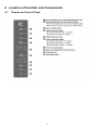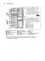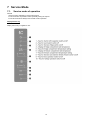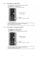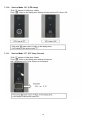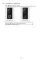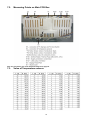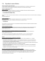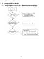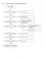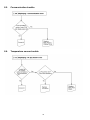
1
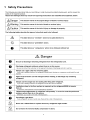
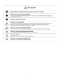
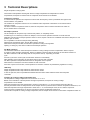
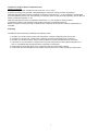
Order Number GORR1405001CE
REFRIGERATOR-FREEZER
Model No. NR-BN34FX1
Model No. NR-BN34FW1
Product-Color
X:Stainless
W:White
Destination E(Europe Continental)
B(U.K.)
TABLE OF CONTENTS
1
2
3
4
5
6
7
8
9
10
PAGE
Safety Precautions----------------------------------------------- 2
Specifications ----------------------------------------------------- 5
Technical Descriptions ----------------------------------------- 6
Location of Controls and Components ------------------- 8
Installation Instructions ---------------------------------------10
Operating Instructions-----------------------------------------12
Service Mode -----------------------------------------------------15
Troubleshooting Guide ----------------------------------------26
Disassembly and Assembly Instructions ---------------32
Schematic Diagram ---------------------------------------------45
PAGE
11 Exploded View and Replacement Parts List ----------- 46
© Panasonic Corporation 2014 Unauthorized copying and distribution is a violation of law.
1 Safety Precautions
2
3
4
2 Specifications
Model
Destination
Total effective volume capacity
Volume capacity
External dimensions
Fridge compartment (PC)
NR-BN34FX1
NR-BN34FW1
Europe – U.K.
339 L
254L
Freezer compartment (FC)
85 L
Width/ Depth/ Height (mm)
600 mm x 640 mm x 2,000 mm
side : 20 mm or more
Installation size
Back : 50 mm or more
Top : 150 mm or more
Power supply plug
Rating
250V/10A
Power supply code
Length
2050 mm
Interior lamp (LED)
Rating
230V/2W
IEC protection against electric shock classes
Class I
Climate Class
SN-T
Fridge compartment sensor
PCC
ESCOP B57020-M2502
Freezer compartment sensor
FCC
ESCOP B57020-M2502
Ambient temperature sensor
ATC
Not used
Defrost temperature sensor
DFC
ESCOP B57020-M2502
Model
Compressor
Jiaxipera NB1114Y
Rotation speed
2930 rpm
Curled resistance cord (at 25°C)
Model
Overlord relay
Main wiring : 20.3 Ohm
Aux wiring : 18.8 Ohm
B50-120
Operating temperature without power
120 °C
Return temperature
61 °C
Operating current (A)
Fan motor
Model/Rating
Dumper
Rating / Voltage
Defrost heater
Rating
Thermal fuse
Class / Fill
5A
BG1512,220/240V,50/60Hz,2W
12VDC.60mA
190 W
Class II.72 ℃
Oil charge
180ml
Freezing ability
12 kg /24 H
Values of the energy consumption
245kwh/year
Energy efficiency grade
A++
Refrigerant charge
R600a / 60g
Measurement of exterior noise emitted
42 dB
Form polyurethane
Net weight (kg)
Cyclo - pentane
Without packaged
76kg
Name Plate
5
3 Technical Descriptions
Single-compressor cooling system
On the basis of temperature checking with sensor in fridge compartment and temperature in freezer
compartment, the request for switch-on/off of compressor and Fan Motor is set /deleted
Compressor operation
In normal mode of operation the compressor functions with the frequency which is prescribed with regard to the
actual conditions of regulations.
The condition for compressor switch-on is not considered if the compressor is locked due to min switch-off time
which is 5 minutes
The same is valid for compressor switch-off, when the compressor does not switch off until the min switch-on
time is reached which is 5 minutes.
PC Damper operation
The PC Damper can be opened only to the extreme position, or completely closed.
At switching-on it is necessary to set the PC Damper, so that it can be opened and closed. It is reset when the
parameter “max time of PC Damper position” which is 6 hours, expires. This time is considered when the PC Damper is in one
position, open or closed.
It is not possible to set the PC Damper during defrosting.
Whenever the PC Damper opens, the Fan Motor starts to function.
When the PC Damper is closed, the Fan Motor operates according to its regulation.
Opening or closing any door does not affect the PC Damper operation.
Fan Motor operation
The Fan Motor switches on when the request is made for cooling of fridge or freezer compartment. When a request
is made for cooling of fridge compartment, first the PC Damper opens and after 30 seconds, the Fan Motor switches on.
Fan Motor switches on with time delay after the compressor start-up - depending on the last
cycle.
If the last cycle was a normal cycle, the Fan Motor switches on immediately.
After defrosting of the evaporator, the Fan Motor starts to function after 4 minutes.
Fan Motor operation is suspended if the freezer or refrigerator door is opened.
When the door is closed, the Fan Motor switches-on after 5 seconds.
If the door is open for 20 minutes, normal operation of Fan Motor continues as prescribed by regulation of cooling.
LED Lamp
Fridge compartment LED Lamp switches on when the door opens.
Fridge compartment LED Lamp switches off when the door closes.
In case of open door, the incorporated time limitation becomes active which switches off the LED Lamp after
10 minutes
Condition for cooling of fridge compartment (PC)
The temperature in fridge compartment can be set from +1 to +9 °C.
Based on the verification of the temperature in fridge compartment, the request for cooling of fridge
compartment is set or deleted.
When the temperature in fridge compartment is equal to or rises above +1 °C, the PC Damper opens and after 30
seconds (Fan Motor switch-on delay time due to PC Damper switch-on) the Fan Motor in freezer compartment switches on, too.
When the temperature in fridge compartment is lower than +1 °C, the PC Damper closes, and in case the request for
cooling of freezer compartment is not set, the Fan Motor in freezer compartment switches off.
On the basis of request for cooling of fridge compartment, the PC Damper and Fan Motor in the freezer compartment switch on.
6
Condition for fridge of freezer compartment (FC)
Standard compressor
The temperature in freezer compartment can be set from -16°C to -24°C.
It operates according to the principle of setting/deleting the request for cooling of freezer compartment.
When the temperature in the freezer compartment is equal to or rises above +1 ° C, the compressor and Fan Motor
(in normal operation) switch on or, after the expiry of Fan Motor switch-on delay time after defrosting, the Fan Motor of
freezer compartment switches on, too.
When the temperature in freezer compartment is lower than 0 ° C, the request for cooling of freezer
compartment is deleted; the compressor and Fan Motor of freezer compartment switch off.
Based on request for cooling of freezer compartment the compressor and Fan Motor of freezer compartment are
controlled.
Defrosting
Unconditional start of defrosting is installed in the following cases:
1.
2.
3.
4.
At switch-on of "Fast Freeze" function if the compressor of freezer compartment does not function.
At switch-on of "Super Cool" function if the compressor of freezer compartment does not function.
At switch-on of "Extreme Freeze" function if the compressor of freezer compartment does not function
If, at switch on of "Fast Freeze" or "Super Cool" function the compressor functions without interruption for 1
hour i.e. immediately after the first interruption of operation of compressor.
5. Always after the terminated "Super Cool", "Extreme Freeze" and "Fast Freeze" function.
6. In case when the user interrupts the "Fast Freeze" function later than in 8 h after switching-on this function.
7
4 Location of Controls and Components
4.1.
Display and Control Panel
8
4.2.
Components
9
5 Installation Instructions
10
11
6 Operating Instructions
6.1.
Setting the temperature
6.1.1.
Fridge compartment (PC)
6.1.2.
Freezer compartment (FC)
6.1.3.
Fresh Zone Crisper
6.2.
6.2.1.
Functions
Vitamin LED Mode
12
6.2.2.
Super Cool Mode
6.2.3.
Super Freeze Mode
6.2.4.
Flash Freeze Mode
13
6.2.5.
ECO Mode
6.2.6.
Holiday Mode
6.2.7.
Alarm Mode
6.2.8.
Child safety lock
14
7 Service Mode
7.1.
Service mode of operation
General
• Service mode is intended for service interventions
• In service mode it is possible to select optionally among the outputs
• From service mode we always enter normal mode of operation
Display Panel A’ssy
Display Panel A’ssy on appliance door
15
7.1.1.
How to start
7.1.2.
How to stop
7.1.3.
Summary of Service Mode
16
7.1.4.
Service Mode “00” (Main PCB)
7.1.5.
Service Mode “01” (Display Panel PCB)
17
7.1.6.
Service Mode “02” (Compressor)
7.1.7.
Service Mode “03” (Fan Motor)
18
7.1.8.
Service Mode “04” (Defrost Heater)
7.1.9.
Service Mode”05” (PC Damper)
19
7.1.10. Service Mode “06” (LED Lamp)
7.1.11.
Service Mode “07” (PC Temp. Sensor)
20
7.1.12. Service Mode “08” (FC Temp. Sensor)
7.1.13. Service Mode “09” (Defrost Sensor)
21
7.1.14. Service Mode “10” (Vitamin LED)
22
7.2.
Measuring Points on Main PCB Box
Note: For more detail, refer to the Schematic Diagram on page 45.
7.3.
Value of Temperature sensors
23
7.4.
Operation in case of failure
Failure of magnetic switch (LED Lamp)
In case of failure of magnetic door switch, the LED Lamp stays switched on for 10 minutes, even when door is
closed. During this time the appliance is operating normally and in accordance with the settings.
Failure of Temperature Sensors
Fridge compartment (PC)
Failure of PC sensor in fridge compartment: time algorithm is installed which sets and deletes the request for
cooling of fridge compartment i.e. opening of the PC Damper:
• for 15 minutes the PC Damper is open
• for 30 minutes the PC Damper is closed
When the PC Damper opens, the Fan Motor switches on and when the PC Damper closes, the Fan Motor switches off. Display for
Fridge
temperature displays ''E1''.
Freezer compartment (FC)
Failure of FC sensor in freezer compartment: display shows ''E3''. The request for cooling of freezer
compartment i.e. switch on/off of compressor and Fan Motor is activated in cycles:
• 15 minutes ON.
• 40 minutes OFF.
If the request for Fan Motor operation in one compartment is interrupted and other compartment requires Fan Motor
operation, the Fan Motor functions.
Freezer compartment evaporator
Failure of Defrost sensor on freezer compartment evaporator: start of defrosting according to the prescribed total
time of compressor operation. Defrosting is carried out normally, but the temperature at which the Defrost
heater switches off, is +8°C.
Failure of fridge and freezer compartment Temperature sensor at the same time
In this case the display of temperature in fridge compartment shows "E1" and the display of temperature in
freezer compartment shows "E3".
On models with one-digit temperature display in fridge compartment, "E" and "1" are shown alternately,
with 1-second interval while the regulations function each one in accordance with their time regime.
Alarms
Alarms of too high temperature in fridge/freezer compartment
In case the temperature in fridge compartment exceeds +13 ° C and in freezer compartment -9 ° C, the high
temperature alarm will be activated:
• sound alarm is heard, the key for cancellation of alarm is flashing with frequency 1 Hz (0.5 seconds ON and 5
seconds OFF), and on the display, depending on the compartment in which the temperature has raised above
the alarm temperature, the set temperature is flashing.
• Sound alarm is the interrupted buzzer sound: 15 seconds ON and 15 seconds OFF in the first 5 minutes every hour.
• Sound alarm is cancelled by pressing the key for cancellation of the alarm.
• Flashing of key and set temperature remains active until the appliance has cooled down and the temperature
drops below the alarm value.
• If within 24 hours after the cancellation of the sound alarm the appliance does not cool down below the alarm
temperature, the sound alarm is activated again.
Alarm due to power supply failure (blackout) during appliance operation
In case that during a power failure the appliance has heated up to the alarm temperature (+13°C in fridge or 9°C in freezer compartment), after the restoration of power supply, the alarm of too high temperature is activated.
In case the alarm of too high temperature is activated due to power supply failure, unlike in case of too high
temperature alarm, the number -16 on freezer or +9 on refrigeration display start flashing. In this case the
alarm is active until user’s cancellation.
24
Open door alarm
If the door of fridge or freezer compartment is open for more than 2 minutes, the uninterrupted buzzer sound
will be heard and the key "2" for cancellation of the alarm will be flashing.
When the door is closed, the alarm is canceled.
The sound alarm can also be cancelled by pressing the key "2"; the key flashes until the door is closed.
Child lock
The function is activated by long press on the key "2" for cancellation of the alarm, the display shows "LL".
By pressing any key, the display will show "LL"; when the key is released, the display shows set temperature.
"Child lock" is cancelled by long press on the key "2".
In case the alarm is activated, it can be cancelled with alarm cancellation key without having to leave the "Child lock" mode.
Error display
Error "E1" is shown on temperature display in fridge compartment. For models with single-digit display, the
display alternately shows the errors: 1 second "E", 1 second "number" and 1 second zero.
Error E3 is shown on freezer compartment temperature display.
Error "E0": on models with two displays it is shown on fridge and freezer compartment temperature display.
For models with single-digit display, the display alternately shows the errors: 1 second "E", 1 second "number"
and 1 second zero.
25
8 Troubleshooting Guide
8.1.
Not cooling at all [ Both PC & FC (compressor does not operate)]
26
8.2.
PC is not cooling or poor cooling. [ FC cooling condition is normal]
27
8.3.
FC is not cooling. [ Compressor operate]
28
8.4.
Cooling system trouble.
29
8.5.
Communication trouble.
8.6.
Temperature sensor trouble.
30
31
9 Disassembly and Assembly Instructions
9.1.
Display Panel A’ssy (Display and Control Panel)
Before taking any action, please unplug the power supply.
To separate Display Panel A’ssy from the door, insert flat screw driver (picture B) into the small opening on the down side in the middle of Display Panel A’ssy. Before you do that please protect the door with scotch tape. Carefully lift the screw driver to detach the
Display Panel A’ssy. Be careful not to damage cable with connector.
On the control unit there are two terminal connectors. Right one is for connecting Display Panel A’ssy with power board. Left is for
uploading SW (optional).
NB! Please wear electrostatic discharge wrist band
32
9.2.
LED Lamp PC
9.3.
1. LED Lamp is installed at the ceiling of PC
Main PCB
1. Main PCB is installed at the upper side of refrigerator.
2. Unhook the hook and push the LED cover to the
left.
2. Slide both the Head Panel Cover R and the Head Panel
Cover L to remove.
3. Remove LED Lamp Assy and disconnect the connector.
3. Unscrew the two screws fixing the Head Panel Cover
Center and remove it.
4. Disconnect the connector.
33
9.4.
5. While unhooking the rib at the upper center of PCB box
by inserting the screwdriver, draw out the PCB box
toward you.
Air Flow Ins. PC
1. First, remove the Glass Shelves, Bottle Support and
Drawers, then unscrew the two screws.
6. Unhook the connector’s hook, then disconnect the connectors.
2. Remove the PC Air Duct Lower.
7. Main PCB Assy (Main PCB with PCB box)
34
3. Disconnect the connector of Vitamin LED.
5. Pull the Air Flow Ins. PC slightly from the left side, then
the connector of Air damper can be seen.
4. Remove the PC Duct Upper, then the Air Flow Ins. PC
can be seen.
35
9.5.
Fan Assy
9.6.
1. First, remove the FC Drawers, then unscrew the four
screws.
Door Switch FC
1. First, remove the FC Drawers,
2. Pull the FC Air Duct Cover toward, then the connector of
Fan Motor can be seen.
2. Unscrew the screw fixing the Door Switch Cover.
3. Unhook the six hooks at the back side, then remove the
FC Air Duct Cover.
3. Open the Door Switch Cover.
36
4. Unhook the hook, then remove the Door Switch FC.
5. Disconnect the connector.
37
9.7.
Replacement of PC temperature sensor
4. First crimp the enclosed end splices on conductor of the
new sensor.
Place the enclosed thermo-shrinkable bushing.
Crimp end splices on conductors of cut cable.
1. Release the latches by screwdriver and remove the cover
by hand.
Note: The sensor cover is hooked at two position as
shown in the photo.
2. Cut off the damages sensor at the base of sensor head.
5. Use hair dryer and heat the bushings so that they tightly
wrap the conductors and prevent moisture from breaking
through the joint.
3. Strip off approx. 25mm of additional cable insulation and
5mm of basic insulation of the conductor.
6. Place the sensor into its seat and replace the sensor
cover.
38
9.8.
Positions of Temperature Sensors, Thermal Fuse,
Defrost Heater and PC Door Switch
39
9.9.
5. Remove the PC Door.
Changing The doorway Direction
Warning: Make sure the unit is unplugged
1. Remove the Hinge Cover Upper.
6. Remove the PC Hinge Cover VC.
2. Remove the PC Door Edge Cover Left.
7. Slide the Head Panel Cover Right and Head Panel
Cover Left then remove its.
3. Disconnect the Display Connector.
8. Unscrew the screws fixing the Head Panel Cover
Center and remove it.
4. Unscrew the screws fixing the Upper Hinge.
40
9. While unhooking the rib at the center of PCB box by using
the screwdriver.
13. Unscrew the Middle Hinge fixing screw and remove it.
14. Remove the FC Door.
10. Draw out the PCB box toward you and change the electric wire direction.
15. Remove the Middle Hinge Plugs and the Screw cap
then unscrew the screw.
11. Screw the screws fixing the Head Panel Cover
Center.
16. Screw the screw.
Install the Middle Hinge Plugs and the Screw cap.
12. Slide the Head Panel Cover Left and Head Panel
Cover Right then fix it.
41
17. Lie down the appliance to the back. (min 600mm)
21. Replace the Door Bushing and the FC Door Plug.
CAUTION: Do not damage the outer condenser.
22. Remove the PC Door Limiter Right, then install PC
Door Limiter Left. (You can find the PC Door Limiter
Left in the user manual bag)
18. Replace the Levelling Leg Right with the Lower
Hinge and the Levelling Leg Left. Then raise the
appliance.
23. Turn the Middle Hinge upside down and screw it.
The thick washer on the downside.
19. Remove the FC Door Limiter Right, then install FC
Door Limiter Left. (You can find the FC Door Limiter
Left in the user manual bag)
24. Install the PC Door.
20. Assemble the FC Door.
42
25. Remove the PC Door Edge Cover Left.
29. Install the Hinge Cover.
26. Install the upper Hinge.
30. Fix the Hinge Cover VC and the PC Door Edge
Cover Right.
27. Connect the Display Connector.
31. Remove the Filling Plugs.
28. Screw the Upper Hinge fixing screws.
32. Unscrew the Handles fixing Torx screws using the
Torx screwdriver.
43
33. Screw the Handles to the right side.
34. Install the Filling Plugs to the left side.
44