1
Instruction Bulletin
VD0C32S303A
October 1998
Raleigh, NC, USA
®
ALTISTART 46
Communication Option
MODBUS® RTU, MODBUS ASCII,
UNI-TELWAY™
ASCII Protocol for PC
VW3G46301
User’s Manual
DANGER
HAZARDOUS VOLTAGE
• Read and understand this bulletin in its entirety before installing or
operating ALTISTART controllers. Installation, adjustment, repair and
maintenance of controllers must be performed by qualified
personnel.
• Disconnect all power before servicing the controller.
• Do not touch unshielded components or terminal strip screw
connections with voltage present.
• Install all covers before applying power or starting and stopping the
controller.
• User is responsible for conforming to all applicable code
requirements with respect to grounding all equipment.
• Many parts in the controller, including printed wiring boards, operate
at line voltage. Do not touch. Use only electrically insulated tools
while making adjustments.
Before installing the controller:
• Disconnect all power.
• Place a “Do not turn on” label on the controller disconnect.
• Lock the disconnect in the open position.
Electric shock will result in death or serious injury.
Bulletin No. VD0C32S303A
October 1998
ALTISTART 46 Communication Option
Table of Contents
CHAPTER 1: INSTALLATION AND CONFIGURATION . . . . . . . . . . . . . . . . . . . . . . . . . . 1
INTRODUCTION . . . . . . . . . . . . . . . . . . . . . . . . . . . . . . . . . . . . . . . . . . . . . . . . . . . . . . 1
System Safety . . . . . . . . . . . . . . . . . . . . . . . . . . . . . . . . . . . . . . . . . . . . . . . . . . . . . 2
INSTALLING THE COMMUNICATION OPTION. . . . . . . . . . . . . . . . . . . . . . . . . . . . . . 2
CONNECTING TO A MULTI-DROP BUS . . . . . . . . . . . . . . . . . . . . . . . . . . . . . . . . . . . 3
SUB-D Connector Pin Configuration . . . . . . . . . . . . . . . . . . . . . . . . . . . . . . . . . . . . 3
Connecting to a Standard RS-485 Bus . . . . . . . . . . . . . . . . . . . . . . . . . . . . . . . . . . 4
Connecting to a Standard RS-422 Bus . . . . . . . . . . . . . . . . . . . . . . . . . . . . . . . . . . 4
Connecting to a Standard RS-232C Bus . . . . . . . . . . . . . . . . . . . . . . . . . . . . . . . . 5
WIRING RECOMMENDATIONS . . . . . . . . . . . . . . . . . . . . . . . . . . . . . . . . . . . . . . . . . . 6
Connecting to a UNI-TELWAY Bus with Telemecanique PLC . . . . . . . . . . . . . . . . . 6
Connection Accessories. . . . . . . . . . . . . . . . . . . . . . . . . . . . . . . . . . . . . . . . . . . 7
Sample Network Layout . . . . . . . . . . . . . . . . . . . . . . . . . . . . . . . . . . . . . . . . . . . 8
Connecting to a MODBUS Bus with MODICON™ PLC . . . . . . . . . . . . . . . . . . . . . 8
Connection Accessories. . . . . . . . . . . . . . . . . . . . . . . . . . . . . . . . . . . . . . . . . . . 9
CONFIGURATION. . . . . . . . . . . . . . . . . . . . . . . . . . . . . . . . . . . . . . . . . . . . . . . . . . . . 11
Configuring the Bus Communication . . . . . . . . . . . . . . . . . . . . . . . . . . . . . . . . . . . 12
ASCII Message Format . . . . . . . . . . . . . . . . . . . . . . . . . . . . . . . . . . . . . . . . . . . . . 13
Reading the Configuration . . . . . . . . . . . . . . . . . . . . . . . . . . . . . . . . . . . . . . . . . . 14
Modifying the Configuration . . . . . . . . . . . . . . . . . . . . . . . . . . . . . . . . . . . . . . . . . 14
Modifying the Configuration by Sending a File . . . . . . . . . . . . . . . . . . . . . . . . . . . 15
Configuration Help . . . . . . . . . . . . . . . . . . . . . . . . . . . . . . . . . . . . . . . . . . . . . . . . 15
Information Requests . . . . . . . . . . . . . . . . . . . . . . . . . . . . . . . . . . . . . . . . . . . . . . 15
DIAGNOSTICS . . . . . . . . . . . . . . . . . . . . . . . . . . . . . . . . . . . . . . . . . . . . . . . . . . . . . . 16
Additional Diagnostics . . . . . . . . . . . . . . . . . . . . . . . . . . . . . . . . . . . . . . . . . . . . . . 16
© 1998 Square D All Rights Reserved
i
ALTISTART 46 Communication Option
Table of Contents
Bulletin No. VD0C32S303A
October 1998
CHAPTER 2: CONNECTIONS AND REGISTER DEFINITIONS . . . . . . . . . . . . . . . . . . . 17
COMMUNICATION PRINCIPLES . . . . . . . . . . . . . . . . . . . . . . . . . . . . . . . . . . . . . . . . 17
Power Connections . . . . . . . . . . . . . . . . . . . . . . . . . . . . . . . . . . . . . . . . . . . . . . . . 17
Control Connections . . . . . . . . . . . . . . . . . . . . . . . . . . . . . . . . . . . . . . . . . . . . . . . 17
ATS46 States . . . . . . . . . . . . . . . . . . . . . . . . . . . . . . . . . . . . . . . . . . . . . . . . . . . . 18
Data Structure . . . . . . . . . . . . . . . . . . . . . . . . . . . . . . . . . . . . . . . . . . . . . . . . . . . . 19
Accessing Data . . . . . . . . . . . . . . . . . . . . . . . . . . . . . . . . . . . . . . . . . . . . . . . . . . . 20
Units . . . . . . . . . . . . . . . . . . . . . . . . . . . . . . . . . . . . . . . . . . . . . . . . . . . . . . . . . . . 20
Ranges . . . . . . . . . . . . . . . . . . . . . . . . . . . . . . . . . . . . . . . . . . . . . . . . . . . . . . . . . 20
Power-Up Values . . . . . . . . . . . . . . . . . . . . . . . . . . . . . . . . . . . . . . . . . . . . . . . . . . 20
LINK/LOCAL Management . . . . . . . . . . . . . . . . . . . . . . . . . . . . . . . . . . . . . . . . . . 20
Operation . . . . . . . . . . . . . . . . . . . . . . . . . . . . . . . . . . . . . . . . . . . . . . . . . . . . . 21
ATS46 CONTROLLER REGISTER DESCRIPTIONS . . . . . . . . . . . . . . . . . . . . . . . . . 22
ii
© 1998 Square D All Rights Reserved
Bulletin No. VD0C32S303A
October 1998
ALTISTART 46 Communication Option
Table of Contents
CHAPTER 3: UNI-TELWAY PROTOCOL . . . . . . . . . . . . . . . . . . . . . . . . . . . . . . . . . . . . 31
LIST OF REQUESTS . . . . . . . . . . . . . . . . . . . . . . . . . . . . . . . . . . . . . . . . . . . . . . . . . 31
Identification Request . . . . . . . . . . . . . . . . . . . . . . . . . . . . . . . . . . . . . . . . . . . . . . 31
Status Request . . . . . . . . . . . . . . . . . . . . . . . . . . . . . . . . . . . . . . . . . . . . . . . . . . . 32
Read and Write Objects Requests . . . . . . . . . . . . . . . . . . . . . . . . . . . . . . . . . . . . 32
Example 1: Word Object Type. . . . . . . . . . . . . . . . . . . . . . . . . . . . . . . . . . . . . . 33
Example 2: Byte Object Type . . . . . . . . . . . . . . . . . . . . . . . . . . . . . . . . . . . . . . 34
Event Data . . . . . . . . . . . . . . . . . . . . . . . . . . . . . . . . . . . . . . . . . . . . . . . . . . . . . . 35
REGISTER UPDATE TIMES . . . . . . . . . . . . . . . . . . . . . . . . . . . . . . . . . . . . . . . . . . . . 35
© 1998 Square D All Rights Reserved
iii
ALTISTART 46 Communication Option
Table of Contents
Bulletin No. VD0C32S303A
October 1998
CHAPTER 4: MODBUS PROTOCOL . . . . . . . . . . . . . . . . . . . . . . . . . . . . . . . . . . . . . . . 37
PRINCIPLE OF COMMUNICATION . . . . . . . . . . . . . . . . . . . . . . . . . . . . . . . . . . . . . . 37
Accessible Data . . . . . . . . . . . . . . . . . . . . . . . . . . . . . . . . . . . . . . . . . . . . . . . . . . 38
Exchanges . . . . . . . . . . . . . . . . . . . . . . . . . . . . . . . . . . . . . . . . . . . . . . . . . . . . . . 39
Checking and Supervision . . . . . . . . . . . . . . . . . . . . . . . . . . . . . . . . . . . . . . . . . . 39
MSTR BLOCK . . . . . . . . . . . . . . . . . . . . . . . . . . . . . . . . . . . . . . . . . . . . . . . . . . . . . . . 40
Overview . . . . . . . . . . . . . . . . . . . . . . . . . . . . . . . . . . . . . . . . . . . . . . . . . . . . . . . . 40
Inputs . . . . . . . . . . . . . . . . . . . . . . . . . . . . . . . . . . . . . . . . . . . . . . . . . . . . . . . . . . 41
Outputs . . . . . . . . . . . . . . . . . . . . . . . . . . . . . . . . . . . . . . . . . . . . . . . . . . . . . . . . . 41
Top Node Content . . . . . . . . . . . . . . . . . . . . . . . . . . . . . . . . . . . . . . . . . . . . . . . . . 42
Middle Node Content . . . . . . . . . . . . . . . . . . . . . . . . . . . . . . . . . . . . . . . . . . . . . . 42
Bottom Node Content . . . . . . . . . . . . . . . . . . . . . . . . . . . . . . . . . . . . . . . . . . . . . . 42
Read/Write Operations . . . . . . . . . . . . . . . . . . . . . . . . . . . . . . . . . . . . . . . . . . . . . 42
Control Block . . . . . . . . . . . . . . . . . . . . . . . . . . . . . . . . . . . . . . . . . . . . . . . . . . . . . 43
Register Update Times . . . . . . . . . . . . . . . . . . . . . . . . . . . . . . . . . . . . . . . . . . . . . 43
APPENDIX A . . . . . . . . . . . . . . . . . . . . . . . . . . . . . . . . . . . . . . . . . . . . . . . . . . . . . . . . . . 45
APPENDIX B . . . . . . . . . . . . . . . . . . . . . . . . . . . . . . . . . . . . . . . . . . . . . . . . . . . . . . . . . . 47
APPENDIX C. . . . . . . . . . . . . . . . . . . . . . . . . . . . . . . . . . . . . . . . . . . . . . . . . . . . . . . . . . . 51
iv
© 1998 Square D All Rights Reserved
Bulletin No. VD0C32S303A
October 1998
ALTISTART 46 Communication Option
Chapter 1: Installation & Configuration
CHAPTER 1: INSTALLATION AND CONFIGURATION
INTRODUCTION
The VW3G46301 Communication Option (also referred to as C1 in this
document) is designed for use with the ALTISTART 46 (ATS46) controller,
allowing it to be connected to multi-drop networks using MODBUS RTU,
MODBUS ASCII, or UNI-TELWAY protocols.
As a node on a network, the ATS46 controller can receive and respond to
data messages. The communication option provides access to the
following ATS46 functions:
•
•
•
•
•
configuration of communication parameters
configuration of controller parameters
downloading of settings
control and supervision
monitoring and diagnostics
The VW3G46301 is supplied with a 118 in. (3 m) RS-485 connection
cable fitted with a 9-pin, male/female SUB-D connector.
During the process of commissioning the ATS46 controller for MODBUS
or UNI-TELWAY communications, four ATS46 parameters must be set via
a PC Terminal Emulation Program. The parameters are outlined in
Table 1 on page 12.
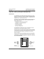
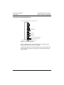
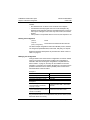
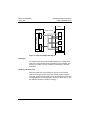
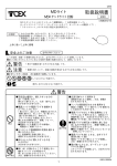
You must connect the PC’s serial COM port to the PLC communication
module (Figure 1 on page 2) with a cable. Order the PC cable, catalog no.
VY1G461510, from a Square D distributor or construct a PC cable using
the pin-out illustrated below.
9-Pin Male
SUB-D
Connector
1
2
3
4
5
6
7
8
9
ATS46 PLC
Communication Module
© 1998 Square D All Rights Reserved
1
2
3
5
4
6
7
8
9
1
3
2
5
4
6
7
8
9
1
6
2
7
3
8
4
9
5
9-Pin Female
SUB-D
Connector
PC
Communication Port
1
ALTISTART 46 Communication Option
Chapter 1: Installation & Configuration
Bulletin No. VD0C32S303A
October 1998
System Safety
WARNING
LOSS OF CONTROL
• Control system designers must consider potential failure modes of control paths and, for
certain critical control functions, provide a means of achieving a safe state during and
after a path failure. An example of a critical control function is emergency stop. Separate
or redundant control paths must be provided for critical control functions.
• System control paths may include communication links. Consideration must be given to
implications associated with unanticipated transmission delays or failures of the link.
Failure to follow this instruction can result in death, serious injury, or equipment
damage. [1]
[1]
For additional information, refer to NEMA ICS 1.1-1984 (latest revision), Safety Guidelines for the Application,
Installation, and Maintenance of Solid State Control.
INSTALLING THE COMMUNICATION OPTION
Before performing any work on the controller, disconnect the power
supply by using the safety switch disconnect or circuit breaker.
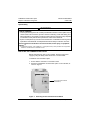
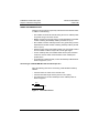
To install the communication option:
1. Ensure that the controller is connected to earth.
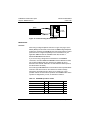
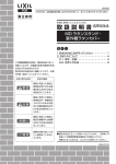
2. Mount the VW3G46301 communication option on the controller, as
shown in Figure 1.
PLC Communication Module
(VW3G46301)
Figure 1:
2
Mounting the PLC Communication Module
© 1998 Square D All Rights Reserved
Bulletin No. VD0C32S303A
October 1998
ALTISTART 46 Communication Option
Chapter 1: Installation & Configuration
3. Connect the PC’s serial COM port to the ATS46 PLC Communication
Module. Use the optional PC cable, catalog no. VY1G461510
(ordered separately), or construct a cable using the pin-out illustrated
on page 1.
4. With power applied to the ATS46 controller, set up the controller
communication parameters (Table 1 on page 12) via the PC Terminal
Emulation Program. If you are using Microsoft® Windows® version
3.11 and earlier, see page 11 for instructions. If you are using
Windows 95 or a later version, refer to Appendix C for configuration
instructions.
5. When configuration is complete, remove power from the ATS46
controller, remove the PC cable, and connect the cable supplied with
this kit to the ATS46 Communications Module. Refer to “Wiring
Recommendations” on page 6 for more information about wiring.
CONNECTING TO A MULTI-DROP BUS
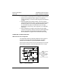
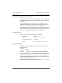
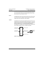
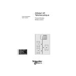
SUB-D Connector Pin Configuration
The transmission interface is electrically isolated from the controller in
accordance with the RS-485 and RS-422 (RS-232C compatible)
standard, and is available on a 9-pin female SUB-D connector.
When using the ASCII protocol for PC, leave the TER/ input unconnected.
When using a bus protocol, connect the TER/ input to the +5 V input.
TER/
0V
D (B)
5V
4.7 kΩ
TX
E
D (A)
0V
5V
100 kΩ
0V
© 1998 Square D All Rights Reserved
5V
RD (B)
&
100 kΩ
Figure 2:
7
3
4.7 kΩ
&
RX
1
8
4
RD (A)
9
5
6
+5 V
TER/
D(B)
RD(B)
5
9
4
8
3
7
2
6
1
SG=RD(B)
0V
TX=D(A)
RX=RD(A)
RS-232
Side view of external contacts
2
0V
Electrical Interface
3
ALTISTART 46 Communication Option
Chapter 1: Installation & Configuration
Bulletin No. VD0C32S303A
October 1998
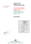
Connecting to a Standard RS-485 Bus
Cable with a 9- to 15-pin SUB-D connector is supplied with the option.
Pins to be used (side view of the 9-pin SUB-D connector)
0V 4
D(B) 7
D(A) 3
TER/ 8
5V 9
120 Ω
Zt line terminator recommended
1 nF at both ends of the line
Figure 3:
RS-485 Interface
Connecting to a Standard RS-422 Bus
Pins to be used (side view of the 9-pin SUB-D connector)
0V 4
D(B) 7
D(A) 3
OR
RD(B) 6
RD(A)
2
TER/
8
5V 9
Figure 4:
4
RS-422 Interface
© 1998 Square D All Rights Reserved
Bulletin No. VD0C32S303A
October 1998
ALTISTART 46 Communication Option
Chapter 1: Installation & Configuration
Connecting to a Standard RS-232C Bus
Pins to be used (side view of the 9-pin SUB-D connector)
1
4
7
6
TX
3
SG 5
RX
2
TER/
8
5V
9
Data
Transmission
Common
Data
Reception
Jumper required for bus protocol;
Do not use for ASCII protocol.
NOTE: Shield connected to ground at the other end.
Figure 5:
RS-232C Interface
When connecting to a PC, use the interconnection cable with a 9-pin
SUB-D connector and the 9- to 25-pin adaptor.
Do not use the TER/ to 5 V jumper for ASCII protocol communication with
a PC. However, the jumper is necessary for communications using the
other protocols.
© 1998 Square D All Rights Reserved
5
ALTISTART 46 Communication Option
Chapter 1: Installation & Configuration
Bulletin No. VD0C32S303A
October 1998
WIRING RECOMMENDATIONS
Follow the wiring practices required by national and local electrical codes
in addition to the following:
• Use metallic conduit for all controller wiring. Do not run multidrop cable
and power wiring in the same conduit.
• Metallic conduit carrying power wiring must be separated from metallic
conduit containing the multidrop cable by at least 8 cm (3 in).
• Non-metallic conduit or cable trays used to carry power wiring must be
separated from metallic conduit containing multidrop cable by at least
30.5 cm (12 in).
• Whenever power wiring and multidrop cable cross, the metallic conduit
and non-metallic conduit or trays must cross at right angles.
• For the multidrop cable, use shielded cable with two pairs of twisted
conductors. Use the cable recommended for each multidrop bus
system shown.
• To equalize the voltage potential, connect the multidrop cable shield as
shown in Figures 3, 4, or 5.
Connecting to a UNI-TELWAY Bus with Telemecanique PLC
Apply the following rules when constructing a UNI-TELWAY multidrop
network:
• Limit the number of nodes on the network to 28.
• Limit the stub cable length at each junction to 20 m (66 ft).
• Terminate each end of each twisted pair of the multidrop cable as
shown in Figure 6.
120 Ω
1 nF
Figure 6:
6
Termination Device
© 1998 Square D All Rights Reserved
Bulletin No. VD0C32S303A
October 1998
ALTISTART 46 Communication Option
Chapter 1: Installation & Configuration
Connection Accessories
To facilitate connecting the controller to the multidrop bus, the following
cable (available in three lengths) is recommended:
• TSX-CSA 100: length 100 m (328 ft)
• TSX-CSA 200: length 200 m (656 ft)
• TSX-CSA 500: length 500 m (1,640 ft)
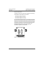
The TSX-SCA62 terminal block (Figure 7) is a passive unit that features
a printed circuit board fitted with screw terminals, enabling two pieces of
equipment to be connected to the bus. There is a jumper in the box which
can be used to connect the end-of-line terminator. Code the PLC address
by setting the microswitches on the printed circuit board inside the box.
These switch settings cannot be used to set the address of the
ALTISTART 46 controller. For more information, refer to the
documentation shipped with the TSX-SCA62.
1
Figure 7:
© 1998 Square D All Rights Reserved
2
TSX-SCA62 Connector
7
ALTISTART 46 Communication Option
Chapter 1: Installation & Configuration
Bulletin No. VD0C32S303A
October 1998
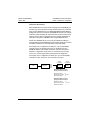
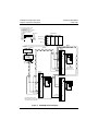
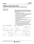
Sample Network Layout
Figure 8 illustrates one possible system configuration involving multiple
ALTISTART 46 controllers, connected to a UNI-TELWAY bus.
TSX-SCM 21.6
TSX-CSB015
TSX-SCA62
TSX-CSAXXX
ALTISTART 46
Controller
Figure 8:
VW3-G46301
VW3-G46301
VW3-G46301
ALTISTART 46
Controller
ALTISTART 46
Controller
Example of Connection to UNI-TELWAY Bus
NOTE: The ground connections between the TSX-SCA62 box and the
ALTISTART 46 controller must be made for good system operation.
Connections should be as short as possible.
Connecting to a MODBUS Bus with MODICON™ PLC
Apply the following rules when constructing a MODBUS multidrop
network:
• Limit the number of nodes on the network to 32, including the master
node.
• Daisy-chain the multidrop cable as illustrated in Figure 9. Do not use
stub connections.
8
© 1998 Square D All Rights Reserved
Bulletin No. VD0C32S303A
October 1998
ALTISTART 46 Communication Option
Chapter 1: Installation & Configuration
Connection Accessories
Many MODICON PLCs cannot initiate messages from a MODBUS port
because they were intended to be used as slave devices only. Therefore,
when using a MODICON PLC, the MODICON BM85 bridge/multiplexer
(bridge mux) must be connected to the MODBUS Plus port. For multiple
controllers, a data-enabled, RS-232C to RS-485 converter must be used.
Figure 9 shows system configuration involving multiple ALTISTART 46
controllers connected to a MODBUS bus, using a MODICON PLC.
NOTE: Your MODBUS device or PLC may be capable of initiating a
message directly from a MODBUS port (it must be a master port). Consult
Schneider Automation for more information (1-800-468-5342).
If the bridge mux is configured as a slave port, only one ALTISTART
controller can be connected to each port. For the bridge mux, the
MODBUS address of the ATS46 controller is used as a slave device
address in configuration setup screen V1. Remember to go to setup
screen V4 to save changes before powering down the bridge mux.
If the bridge mux is configured as a master port, up to 31 ALTISTART
controllers or other devices can be connected to each port.
ATS46
Controller A
PLC
Bridge Mux
Port 1
Port 2
Port 3
Port 4
MODBUS 3
Node
ATS46
Controller B
MODBUS 7
Node
MSTR Block Address routing
talking to ATS46 Controller A:
Address first device
12
Address second device 1 (Port 1)
3
Address third device
MSTR Block Address routing
talking to ATS46 Controller B:
Address first device
Address second device
Address third device
© 1998 Square D All Rights Reserved
12
1 (Port 1)
7
9
ALTISTART 46 Communication Option
Chapter 1: Installation & Configuration
Bulletin No. VD0C32S303A
October 1998
▲ Use Standard Modem Cable
DB 25 Male/DB 9 Female
GC BC00 301
and a Male-to-Male 9-Pin Adapter
or wire your own cable using
the following connections:
DB9 Male
RXD 2
TXD 3
DTR 4
GND 5
DSR 6
RTS
CTS
DB 25 Male
2 TX
3 RX
4 RTS
5 CTS
6 DSR
7 GND
20 DTR
Modicon PLC
CPU
I/O
I/O
I/O
MB Slave Port
MB Slave Port
MB+ Port
RS-485
ModBus+
MB+ Address 10
RS-485
Wiring
Interface *
Modicon BM85
bridge mux
2
4
1
3
▲
RS-232C to RS-485
data enabled
converter
D(A) D(B) 0V
1 2 3 4 5
WHT/
BLU
WHT/
BLU
BLU/
WHT
BLU/
WHT
Wiring
Interface
WHT/
BLU
BLU/
WHT
*
1
2
3
4
5
6
7 D (A)
8
9
10
ATS46 Controller 4
11
12
13
14 D (B)
15 0 V
G
G
Wiring Interface
WHT/BLU
BLU/WHT
* 810-289-020 Female 15-Pin
Wiring Interface: Telemecanique ABE-6SD15F or WAGO 810-289/W02
Cable: Belden 9841 or equivalent
Figure 9:
10
1
2
3
4
5
6
7 D (A)
8
9
10
11
12
13
14 D (B)
15 0 V
G
G
1
2
3
4
5
6
7 D (A)
8
9
10
11
12
13
14 D (B)
15 0 V
G
G
ATS46 Controller 5
ATS46 Controller
Slave Address 5
Route Address 10:4:5
*
ATS46 Controller n
MODBUS Network Diagram
© 1998 Square D All Rights Reserved
Bulletin No. VD0C32S303A
October 1998
ALTISTART 46 Communication Option
Chapter 1: Installation & Configuration
CONFIGURATION
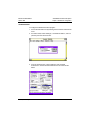
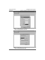
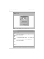
To configure the Windows Terminal program:
1. Access the Terminal menu by selecting the Accessories and Terminal
icons.
2. As shown below, select «Settings», «Terminal Emulation», and TTY
(Generic) from the Terminal menu.
3. From the Terminal menu, select «Settings» and «Terminal
Preferences». Set the Terminal Preferences to the values shown
below.
© 1998 Square D All Rights Reserved
11
ALTISTART 46 Communication Option
Chapter 1: Installation & Configuration
Bulletin No. VD0C32S303A
October 1998
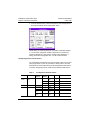
4. From the Terminal menu, select «Parameters» and «Configuration».
Set Communications to the values shown below.
NOTE: When you select the parity bit, the number of data bits changes
to 7. In this case, change the number of stop bits to 2 to restore the
number of data bits to 8. Then set the number of stop bits back to 1.
Saving the terminal configuration to a *.trm file is recommended.
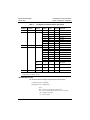
Configuring the Bus Communication
The configuration parameters for the communication option can be read
using any protocol, but can only be written in ASCII protocol. To select
ASCII protocol, install a cable with no jumper strap between TER/ and 5 V.
To use the configured protocol, install a jumper between TER/ and 5 V.
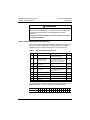
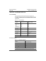
Table 1:
Address Parameter
W2290
Configuration Parameter Values
Selected
Protocol
Permitted
ASCII
Values
Product Address
(ADR)
ADR
0
1-31
W2291
Protocol (PRO)
12
0
NO
Address not configured
Value
PRO
UNI-TELWAY
Default Comments
2
UTW
3
Reserved
MODBUS
RTU
4
RTU
MODBUS
ASCII
5
ASC
Station address
2
© 1998 Square D All Rights Reserved
Bulletin No. VD0C32S303A
October 1998
ALTISTART 46 Communication Option
Chapter 1: Installation & Configuration
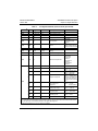
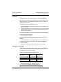
Table 1:
Address Parameter
W2292
W2293
Configuration Parameter Values (Continued)
Selected
Protocol
Speed (SPD)
SPD
Default Comments
7
2
300
300 bits/s
3
600
600 bits/s
4
1200
1200 bits/s
5
2400
2400 bits/s
6
4800
4800 bits/s
7
9600
9600 bits/s
8
19200
Format (FOR)
FOR
UTW
[1]
Permitted
ASCII
Values
2
8O1 [1]
3
8E1
4
8N1
5
8N2
6
7O1
7
7E1
8
7O2
9
7E2
2
8O1
MODBUS
RTU
2-5
MODBUS
ASCII
2-9
19200 bits/s
2
8 bits/odd parity/1 stop bit
Cannot be modified for
UNI-TELWAY
Read as number of bits, parity (O=odd, E= even, N= none), number of stop bits
Example: 8O1 = 8 odd bits, 1 stop bit.
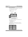
ASCII Message Format
The format of ASCII messages using Terminal is shown below.
PC (Master) question: ?{Data}{End}
ATS46 (Slave) answer: >{Data}{CR LF}
where:
Data = question or response data in ASCII format
End = one or two end characters (CR or LF or CR LF or LF CR)
CR = carriage return (H‘OD’)
LF = line feed (H‘OA’)
© 1998 Square D All Rights Reserved
13
ALTISTART 46 Communication Option
Chapter 1: Installation & Configuration
Bulletin No. VD0C32S303A
October 1998
NOTES:
• End characters are not shown in the remainder of this chapter.
• The Windows Terminal program does not use the backspace key
(deleting the last character entered). If the backspace key is used, the
echo of your message on the screen may seem correct, but it will be
refused.
• If the question or a requested value is not correct, the response is >N.
Reading the Configuration
question:
?CONF
response:
(factory configuration)
>CONF:PRO:UTW ADR:NO SPD:9600 FOR:8O1
The above sample configuration reads: UNI-TELWAY protocol, address
not configured, speed 9600 bits/s, 8-bit format, odd parity, one stop bit.
Response parameter descriptions are provided in the ASCII column of
Table 1 on page 12.
Modifying the Configuration
Changes made to the communication configuration are saved in ATS46
memory. The response format when modifying the configuration is
identical to that when entering the configuration. The parameters are
listed in Table 1 on page 12, and they can be modified one at a time
(Example 1) or several in one question (Example 2). The mnemonics are
provided in the ASCII column and the possible protocol values in the
Permitted Values column of Table 1.
Example 1
address 1
UNI-TELWAY protocol
speed 19200 bits/s
8-bit format, odd parity,1 stop bit
?ADR=1
?PRO=UTW
?SPD=19200
?FOR=8O1
Example 2
MODBUS RTU protocol, address 1,
?CONF=PRO=RTU ADR=1 SPD=4800
speed 4800 bits/s, 8-bit format,
FOR=8N1
no parity, 1 stop bit
UNI-TELWAY protocol,
speed 19200 bits/s (format is fixed,
address not modified)
?CONF=PRO=UTW SPD=19200
Any parameters that are not modified retain their previous values (ensure
that these values are correct).
14
© 1998 Square D All Rights Reserved
Bulletin No. VD0C32S303A
October 1998
ALTISTART 46 Communication Option
Chapter 1: Installation & Configuration
Modifying the Configuration by Sending a File
It is possible to enter the configuration in a text file, prepared using a text
editor (Windows Notepad type), to avoid typing the same command line
repeatedly.
Enter the configuration you wish to send (e.g., ?CONF=PRO=UTW
ADR=1 SPD=9600) in the notepad and save the file. The file must end
with a CR or LF. Press Enter at the end of the configuration line.
In the Windows Terminal «Transfer» menu, select «Send a text file», then
select the file previously saved. The file is immediately transmitted via the
Serial Link. A message confirming the transfer is displayed.
Configuration Help
Help is provided for the mnemonics used. For example:
To access Help:
?HELP
Response:
?HELP PRO ADR SPD FOR
To access parameter Help:
?HELP PRO
Response:
>HELP PRO: PRO=UTW or RTU, ASC
Information Requests
To identify the ATS46 controller type and option being used, send the
following request:
Information
request:
?INFO
Response:
>INFO:C1:V:1.0 IE01H TYPE:01H CS9B5AH ATS46D32:V1.1
In the above example, the communication option C1 (=VWG46301) has
software version V1.0 IE01 (E= version index), a standard type with a
program that contains H’9B5A’ as checksum. The ATS46 controller type
is ATS46D32 with software version V1.1.
NOTE: The checksum listed above is not an exact value for V1.0 software,
but is provided to illustrate the Response format.
© 1998 Square D All Rights Reserved
15
ALTISTART 46 Communication Option
Chapter 1: Installation & Configuration
Bulletin No. VD0C32S303A
October 1998
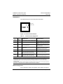
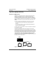
DIAGNOSTICS
Two indicator lamps are on the front panel of the option:
COM
Red LED
OK
Green LED
RS232/422/485
Figure 10: Communication Interface
Table 2:
Communication Diagnostics
OK Lamp
COM
Probable Cause
Green Lamp Red
Corrective Action
1
0
Normal operation, bus and controller present OK
0
0
Switched off, powered off
Check the interface or the communication
option.
0
1
Bus communication fault
Check the communication bus and the
connections. Check the switches on the
subscriber sockets.
0
1/10 [1]
(6x)
Character error
Check the communication configuration or
the TER/-5 V strap (absent in ASCII
protocol/present in bus protocol).
1/10
0
Communication option not configured
Configure the communication option.
1/2
0
Communication fault between the
communication option and the ATS46
controller (bus cable connected to option)
Check the 6-pin connector between the
option and the ATS46 controller.
1/2
1
Communication fault between the
communication option and the ATS46
controller (PC cable connected to option)
Check the 6-pin connector between the
option and the ATS46 controller.
Lamp status:
0 = off
1 = on
1/2 = slow flashing (500 ms)
1/10 = fast flashing (100 ms)
[1]
This display flashes for 600 ms (3x on and 3x off) if an incorrect character has been received. The short flashing
is repeated after a period of five seconds if an incorrect character is received. This only occurs when the
communication option is set for communication fault (no message received for 10 s in bus communication or 1 s
in ASCII protocol).
If the option never changes to normal operation, this display indicates that the wiring is correct (except, perhaps,
for the TER/–5 V strap), but that the configuration speed or format is not suitable.
Additional Diagnostics
For an explanation of fault code registers, refer to Table 9 on page 27.
16
© 1998 Square D All Rights Reserved
Bulletin No. VD0C32S303A
October 1998
ALTISTART 46 Communication Option
Chapter 2—Register Definitions
CHAPTER 2: CONNECTIONS AND REGISTER DEFINITIONS
COMMUNICATION PRINCIPLES
Power Connections
The power wiring to the ALTISTART 46 (ATS46) controller can be
connected in accordance with the diagrams shown in the ATS46 user
guide, part number VD0C32S301.
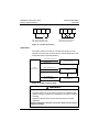
Control Connections
The connection from STOP to PL must be made at all times for the
controller to run. As shown in Figure 11 on page 18, the control
connection scheme depends on whether the start command is to be
issued via the terminal strip (LOCAL mode) or through the PLC (LINK
mode). The control scheme also depends on the setting of the DLI bit
(W4060,1), as shown in Table 3.
Table 3:
Setting the DLI Bit
LOCAL Mode
(DLI = 0)
LINK Mode
(DLI = 1)
LI–PL connection = 0
(not connected)
Start command only by PLC.
Standard operation — can configure
LI ignored unless configured
LI for all available options
for local control.
LI–PL connection = 1
(connected)
Cannot switch to LINK mode if LI is
configured for local control. Other LI
configurations can be used but will
not prevent switching to LINK mode.
Start command only by
terminal input
WARNING
UNINTENDED EQUIPMENT OPERATION
If DLI = 1, the logic input (LI) is ignored unless configured for Force to
Local Control (W4022=4). All other functions of the logic input must be
actuated through the PLC command (W4060).
Failure to follow this instruction can result in death, serious injury,
or equipment damage.
© 1998 Square D All Rights Reserved
17
ALTISTART 46 Communication Option
Chapter 2—Register Definitions
S
T
O
P
R
U
N
Bulletin No. VD0C32S303A
October 1998
L
I
S
T
O
P
P
L
R
U
N
L
I
LINK
P
L
LOCAL
STOP
RUN
Only connect from STOP to PL
when starting solely from a PLC.
Use 3-wire control to start from
the terminal or from a PLC.
Figure 11: Control Connections
ATS46 States
If automatic restart is not used, the controller state is either no fault
(ready/run) or fault. Figure 12 shows the four controller states which exist
if automatic restart is selected (W4035,1).
Automatically resettable fault
Automatic reset
No Fault
(normal operation)
Automatic fault reset
Fault resettable on request
Reset request
Fault resettable
on request
Non-resettable
fault
Non-resettable fault
Controller re-initialization
Non-resettable fault
Figure 12: ATS46 Controller States
WARNING
UNINTENDED EQUIPMENT ACTION
• Automatic restart can only be used for machines or installations that
present no danger to personnel or equipment in the event of automatic
restarting.
• Equipment operation must conform with national and local safety
regulations.
Failure to follow this instruction can result in death, serious injury, or
equipment damage.
18
© 1998 Square D All Rights Reserved
Bulletin No. VD0C32S303A
October 1998
ALTISTART 46 Communication Option
Chapter 2—Register Definitions
Descriptions of each ATS46 state are provided below.
State
1 No Fault
Standard Mode (W4035,1 = 0)
Auto Reset Mode (W4035,1 = 1)
Controller is ready or running
Controller is ready or running with no fault
with no fault condition detected. condition detected.
2 Automatic Reset Not taken into account.
Fault
This state follows a fault that can be reset
without further intervention.
If R1 is configured as a fault relay, this type of
fault does not cause the R1 relay to change
state.
If R1 is configured for control of an isolation
contactor, this type of fault causes the R1
relay to change state.
3 Fault Reset on
Request
Causes the R1 relay to change
state. Relay will re-energize
when a new run command is
issued and the fault has cleared.
When a fault is encountered, the drive will
check to see if (W4035,1=1) is set. If true, the
drive will reset once the fault is cleared. This
will occur only if the fault is an auto restart
type. Refer to the Soft Start Controller User’s
Manual, part number VD0C32S301, for more
information on faults.
4 Non-resettable
Fault
Requires cycling of control
power to reset.
Requires cycling of control power to reset.
Data Structure
The adjustment, control, supervision, and monitoring of ATS46 controllers
are performed using data (or objects) that are specific to this product.
The data consists of:
• Bits that execute logic commands and are designated Bi, where
i = Bit number. For example, B1 = Starter reset (request for online
reset).
• Words (of 16 bits) are designated Wx, where x is a word number.
Words are used to save either integer values (0 to 65535) or 16
independent logic states that are called registers.
Example:
W4028 = Boost level (digital value)
W4061 = Controller status register (16 status bits)
NOTE: Bit numbers are displayed as 0 to 9, then A to F. For example,
W4061,1 designates Bit 1 of register 4061. W4061,F designates Bit F of
register 4061.
© 1998 Square D All Rights Reserved
19
ALTISTART 46 Communication Option
Chapter 2—Register Definitions
Bulletin No. VD0C32S303A
October 1998
Accessing Data
The tables at the end of this chapter list the parameters that can be
accessed via the communication link. The exact function of each
parameter and its effect on the behavior of the controller are described in
the ATS46 user guide, part number VD0C32S301.
Data including fault and monitoring information can only be read. Any
attempt to write to this data will be refused. The bits and words
corresponding to the adjustment, configuration and command
parameters can be written to as well as read.
Units
Words are expressed as unsigned integer values (0 to 65535), using the
units defined in the tables at the end of this chapter. For values that are
listed as decimal units in the register definition tables, the decimal point is
implied.
Example: W4037 = Initial torque as a percentage of Tn (e.g., 50 = 50% of Tn)
Ranges
The range permitted by the controller is specified for each parameter.
Where noted, 0 in the range column indicates that when the parameter is
set to 0, the function is disabled.
Example: When W4036 = 0, no maximum torque limit is specified;
otherwise, the adjustment range is from 10 to 200 (as a percentage of Tn).
Power-Up Values
Each time the ATS46 controller is powered up, it is initialized with the
configuration and adjustments stored in EEPROM memory (in LINK
mode, store adjustments with W4060,E or return to factory settings with
W4060,D).
The controller is systematically set to LOCAL control mode (commands
are expected on the terminal block). To control the ATS46 controller from
a multi-drop bus, it is necessary to assign the commands to LINK mode
by setting W4060,1 to 1.
LINK/LOCAL Management
Two control modes are provided for ATS46 controller operation:
• LOCAL mode via 2- or 3-wire terminal block control
• LINK mode via a PC or a PLC
20
© 1998 Square D All Rights Reserved
Bulletin No. VD0C32S303A
October 1998
ALTISTART 46 Communication Option
Chapter 2—Register Definitions
ATS46 operating modes are only effective for accessing the command
parameters and have no effect on the configuration, adjustment, or
monitoring parameters.
Table 4:
LINK/LOCAL Transition Parameters
Parameter
Description
Command bit B2 (DLI)
Assigns commands to LINK/LOCAL mode
Command word W4060,1 (DLI)
Same as command bit B2 (DLI)
Command bit B4 (NTO)
No time out
Command word W4060,4 (NTO)
Same as command bit B4 (NTO)
Configuration word W4022 (LI)
Assigns LI to LOCAL mode
Configuration word W4029 (STY)
Selects stop type via LI_STOP
Monitoring word W4061,0 (LOC)
LOCAL mode = 1, LINK mode = 0
Monitoring word W4061,5 (FLO)
LOCAL mode = 1, not LOCAL mode = 0
Monitoring word W4066,0 (LIO)
State of LI (0=low, 1=high)
Operation
In LOCAL mode, the terminal block is active and must be used to start
and stop the ATS46 controller.
In LINK mode, the serial link has write access to the commands. Only the
STOP terminal is active and will override all other commands.
If the controller is configured for LOCAL mode and LI is configured for
local control, activating LI will prevent the controller from switching to
LINK mode.
When the controller is switched out of LINK mode, the controller will run
if there is a RUN command present at the terminal strip.
In LINK mode, messages must be sent to the controller regularly (at least
one message every 10 seconds with UNI-TELWAY, MODBUS ASCII, and
MODBUS RTU protocol and every second in ASCII protocol). If a
message is not received, a controller serial link fault (SLF) occurs. The
communication check can be inhibited by setting bit NTO to 1, which
prevents the SLF fault from displaying. This is useful in setup and
troubleshooting; however, NTO should be set to 0 for normal serial link
command operation.
© 1998 Square D All Rights Reserved
21
ALTISTART 46 Communication Option
Chapter 2—Register Definitions
Bulletin No. VD0C32S303A
October 1998
WARNING
LOSS OF CONTROL
Setting B4 or W4060,4 (NTO) to 1 disables serial link fault protection.
Provide alternate control paths when disabling serial link fault
protection.
Failure to follow this instruction can result in death, serious injury
or equipment damage.
ATS46 CONTROLLER REGISTER DESCRIPTIONS
NOTE: When using the MSTR block (refer to “MSTR Block” on page 40),
add 1 to the register number. Bit 0 is always the right-most or leastsignificant bit. Bit F is always the left-most or most-significant bit.
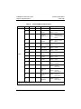
Table 5:
Command Bits (read and write)
Bit Name Description
Function
B0
RST
Controller reset command
Acknowledges a correctable fault
W4060,0
and resets the fault relay.
Address
B1
DLI
Command assigned to
LINK/LOCAL mode
LINK = 1, LOCAL = 0
The controller can only be
controlled via the serial link (bus
or PC) or via its terminal block.
W4060,1
B2
EXT
External fault
The controller triggers an EtF
fault.
W4060,2
B3
—
Reserved
—
—
W4060,4
B4
NTO
No Time Out
The controller does not trigger
an SLF fault if messages are not
received within 10 s.
B5
RUN
Start command
0=inactive; 1=active
W4060,5
B6
CAF
Braked stop command
0=inactive; 1=active
W4060,6
B7
CAD
Decelerated stop command 0=inactive; 1=active
W4060,7
B8
CAL
Freewheel stop command
0=inactive; 1=active
W4060,8
B9
—
Reserved
—
—
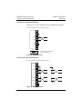
The bit designations in Table 5 follow UNI-TELWAY protocol. When using
MODBUS protocol, observe the following bit order designation.
22
UNI-TELWAY
0
6
7
8
9
A
B
C
D
E
F
MODBUS
16 15 14 13 12 11 10
9
8
7
6
5
4
3
2
1
1
2
3
4
5
© 1998 Square D All Rights Reserved
Bulletin No. VD0C32S303A
October 1998
ALTISTART 46 Communication Option
Chapter 2—Register Definitions
WARNING
UNINTENDED EQUIPMENT OPERATION
There is a shift of 1 between the address in UNI-TELWAY and
MODBUS protocols. When using MODBUS protocol, add 1 to each
address listed in the following tables.
Failure to follow this instruction can result in death, serious injury,
or equipment damage.
© 1998 Square D All Rights Reserved
23
ALTISTART 46 Communication Option
Chapter 2—Register Definitions
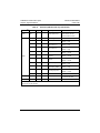
Table 6:
Address [1] Name Range
Bulletin No. VD0C32S303A
October 1998
Adjustment Words (read and write)
Unit
Description
Possible Values
% of Tn
Max torque during
acceleration
0 = off (CLP must be on for
value to be used)
W4036
TLI
0 [2]
10–200
W4037
TQ0
0–100
% of Tn
Initial torque during
acceleration
W4038
EDC
0–100
% of Tn
End of deceleration ramp
threshold
W4039
ILT
150–700
% of In
max 500% ICL
Current limit
0 = off
W4040
OIL
0 [2]
50–300
% of In
Current limit alarm
0 = off
W4041
BRC
0–100
—
Braking current
W4042
EBA
20–100
% of braking time Adjustment of braking time
W4043
ACC
1–60
S
W4044
DEC
1–60
S
W4045
Acceleration ramp time
Deceleration ramp time
Reserved
W4046
Reserved
W4047
Adjustment of deceleration
gain
[1]
[2]
RGC
0–100
—
When using MODBUS protocol, add 1 to the address.
When the parameter is set to 0, the function is disabled.
Table 7:
Address
[1]
Name Range
W4018–4019
Configuration Words (read and write)
Unit
Description
Possible Values
Reserved
Read at 8000 H
W4022
LI
0–8
Logic input LI assigned
0=not assigned
1=force freewheel
2=external fault [2]
3=reserved
4=local control
5=cascading motor control
6=reserved
7=motor overload reset
8=fault reset
W4023
LO1
0–2
Logic output LO1 assigned
0=not assigned
1=motor thermal alarm
2=motor powered
0–5
0=not assigned
1=motor current (A)
2=motor torque (% Tn)
Analog output AO assigned
3=motor thermal state
4=power factor
5=active power
W4024
[1]
[2]
[3}
24
AO
When using MODBUS protocol, add 1 to the address.
In LINK mode, an external fault must be indicated by the PLC. Do not connect the external fault indication device
to the logic input on the ATS46 controller, as the signal will be ignored.
When the parameter is set to 0, the function is disabled.
© 1998 Square D All Rights Reserved
Bulletin No. VD0C32S303A
October 1998
Table 7:
ALTISTART 46 Communication Option
Chapter 2—Register Definitions
Configuration Words (read and write) (Continued)
Address [1] Name Range
Unit
Description
W4025
%
Analog output scale
ASC
50–500
W4026
IN
50–130% ICL 0.1 A
Motor nominal current
W4027
LSC
20–90
% losses
Stator loss compensation
W4028
BST
0 [3], 50–100
% of V
Possible Values
Voltage boost level
W4029
STY
0–2
0=freewheel
Stop type selection via logic
1=deceleration ramp
input LI_STOP
2=braking
W4030
PHR
0–2
Default assigned to phase
rotation
W4031
ULL
0 [3] or 20–100 % of Tn
Underload trip threshold
W4032
TBS
0–999
seconds
Time adjustment before
starting
W4033
TLS
0 [3], 10–999
seconds
Start time too long
W4034
THP
0–7
CNF
Motor thermal protection
[2]
[3}
0=protection inhibited
1=sub-class 2
2= class 10A
3=class 10
4=sub-class 15
5=class 20
6=sub-class 25
7=class 30
Configuration register
CLP
0–1
Torque control
4035,0 = 0 off
4035,0 = 1 on
ARS
0–1
Automatic reset
4035,1 = 0 manual reset
4035,1 = 1 auto reset
R1
0–1
Relay R1 assignment
4035,2 = 0 fault relay
4035,2 = 1 isolating relay
(Bit 4060,0 controller reset
function clears fault when
this relay is used as a fault
relay.)
LO2
0–1
Logic output LO2
assignment
4035,3 = 0 not assigned
4035,3 = 1 current
threshold alarm
AO1
0–1
Analog output range
4035,4 = 0 0–20 mA
4035,4 = 1 4–20 mA
SST
0–1
Select test operation on a
low power motor
4035,5 = 0 not assigned
4035,5 = 1 test function
CSC
0–1
Cascading motor
4035,6 = 0 not active
4035,6 = 1 active
Reserved
4035,7–F
W4035
[1]
0=off
1=direct rotation direction
2=reverse rotation direction
When using MODBUS protocol, add 1 to the address.
In LINK mode, an external fault must be indicated by the PLC. Do not connect the external fault indication device
to the logic input on the ATS46 controller, as the signal will be ignored.
When the parameter is set to 0, the function is disabled.
© 1998 Square D All Rights Reserved
25
ALTISTART 46 Communication Option
Chapter 2—Register Definitions
Table 8:
Address
[1]
Name
Range
Command Word (read and write)
Unit
Description
Possible Values
CMD
Command register
RST
Controller reset
command
W4060,0 = 0 inactive
W4060,0 = 1 active
DLI
Commands
assigned over link
W4060,1 = 0 commands not
assigned over link
W4060,1 = 1 commands assigned
over link
EXT
External fault
command
W4060,2 = 0 inactive
W4060,2 = 1 active on positive
edge [2]
DMC
Motor deceleration
control in cascade
W4060,3 = inactive
W4060,3 = 1 active
NTO
No time out
(no SLF fault)
W4060,4 = 0 enable
W4060,4 = 1 disable
RUN
Start command
W4060,5 = 0 inactive
W4060,5 = 1 active
CAF
Braked stop
command
W4060,6 = 0 inactive
W4060,6 = 1 active
CAD
Decelerated stop
command
W4060,7 = 0 inactive
W4060,7 = 1 active
CAL
Freewheel stop
command
W4060,8 = 0 inactive
W4060,8 = 1 active
RTH
Reset motor thermal W4060,A = 0 no
state
W4060,A = 1 yes/reset
TRE
Reset elapsed time
W4060,C = 0 inactive
W4060,C = 1 active on
positive edge
INT
Recall factory
setting
W4060,D = 0 inactive
W4060,D = 1 active on
positive edge [2]
MRE
W4060,E = 0 inactive
Store adjustments in
W4060,E = 1 active on
EEPROM
positive edge [2]
RRE
Recall adjustments
in EEPROM
W4060
26
Bulletin No. VD0C32S303A
October 1998
[1]
When using MODBUS protocol, add 1 to the address.
[2]
Bit returns to 0 after operation.
W4060,F = 0 inactive
W4060,F = 1 active on
positive edge [2]
© 1998 Square D All Rights Reserved
Bulletin No. VD0C32S303A
October 1998
ALTISTART 46 Communication Option
Chapter 2—Register Definitions
Table 9:
Address
[1]
Name
Range
Monitoring Words (read only)
Unit
Description
Possible Values
ETA
Controller status
register
LOC
Local/Link mode
W4061,0 = 0 local
W4061,0 = 1 link
RDY
Controller status
W4061,1 = 0 not ready
W4061,1 = 1 ready
FAI
Controller faulted
W4061,2 = 0 normal operation
W4061,2 = 1 faulted
Stopped after request
via terminal block
W4061,3 = 0 false
W4061,3 = 1 true
FLO
Local control
W4061,5 = 0 false
W4061,5 = 1 true
NTO
Communication check
inhibited
W4061,6 = 0 false
W4061,6 = 1 true
Current alarm threshold
W4061,7 = 0 false
W4061,7 = 1 true
Steady state
W4061,8 = 0 false
W4061,8 = 1 true
Short-circuit
W4061,9 = 0 false
W4061,9 = 1 true
Stop phase
W4061,A = 0 false
W4061,A = 1 true
Acceleration phase
W4061,B = 0 false
W4061,B = 1 true
OVL
Motor thermal alarm
W4061, C = 0 false
W4061,C = 1 true
LIM
Current limited
W4061,D = 0 false
W4061,D= 1 true
NLP
No mains supply
W4061,E = 0 false
W4061,E = 1 true
Mains supply frequency
W4061,F = 0 50 Hz
W4061,F = 1 60 Hz
W4061
SST
W4062
LCR
0–999
A/10
W4063
LTR
0–255
% of Tn
Motor current
Motor load state
W4064
LTH
0–250
%
Motor thermal state
[1]
When using MODBUS protocol, add 1 to the address.
[2]
Bit returns to 0 after operation.
© 1998 Square D All Rights Reserved
27
ALTISTART 46 Communication Option
Chapter 2—Register Definitions
Table 9:
Address [1] Name
Range
W4065
0–2
PHR
Bulletin No. VD0C32S303A
October 1998
Monitoring Words (read only) (Continued)
Unit
LIO
W4068
[1] When
[2]
28
Possible Values
Phase rotation state
0=off
1=direct rotation direction
2=reverse rotation direction
State of logic I/O
W4066
W4067
Description
Logic input LI
W4066,0 = 0 low
W4066,0 = 1 high
Logic output LO1
W4066,1 = 0 low
W4066,1 = 1 high
Logic output LO2
W4066,2 = 0 low
W4066,2 = 1 high
Relay R1
W4066,3 = 0 open
W4066,3 = 1 closed
Relay R2
W4066,4 = 0 open
W4066,4 = 1 closed
Vigithem
W4066,5 = 0 thermal overshoot
W4066,5 = 1 closed
Logic input LI_RUN
W4066,6 = 0 low
W4066,6 = 1 high
Logic input LI_STOP
W4066,7 = 0 low
W4066,7 = 1 high
Operating duty switch
W4066,8 = 0 standard
W4066,8 = 1 severe
Reserved
W4066,9–W4066,F
0.01 to 1 displayed as %;
÷ by 100 for actual value
COS
1–100
%
Cos motor power factor
TFR
10–65535
Hours
Elapsed time
using MODBUS protocol, add 1 to the address.
Bit returns to 0 after operation.
© 1998 Square D All Rights Reserved
Bulletin No. VD0C32S303A
October 1998
ALTISTART 46 Communication Option
Chapter 2—Register Definitions
Table 9:
Address [1] Name
Range
DFT
Monitoring Words (read only) (Continued)
Unit
Description
Possible Values
Fault register
Reserved
W4069,0
INF
Internal fault
W4069,1
OCF
Overcurrent fault
W4069,2
PIF
Phase inversion
W4069,3
Reserved
W4069,4
Serial link
W4069,5
SLF
ETF
External fault
W4069,6
STF
Start too long
W4069,7
USF
Mains failure and start
request
W4069,8
PHF
Phase failure
W4069,9
OHF
Controller thermal fault
W4069,A
LRF
Rotor locked in steady
state
W4069,B
OLF
Motor thermal overload
W4069
FRF
W4069,C
W4069,D
Reserved
W4069,E
ULF
Underload
W4069,F
W4070
SAO
Value of analog output
AO
W4071
—
Time before starting
alarm
W4071,0 = 0 inactive
W4071,0 = 1 active
W4072
LPR
Active power
0=inactive
1=active
W4090
PTR
Fault order
W4091
DFT
Fault register repetition
Time counter repetition
(W4068)
W4092
[1] When
[2]
using MODBUS protocol, add 1 to the address.
Bit returns to 0 after operation.
© 1998 Square D All Rights Reserved
29
ALTISTART 46 Communication Option
Chapter 2—Register Definitions
30
Bulletin No. VD0C32S303A
October 1998
© 1998 Square D All Rights Reserved
Bulletin No. VD0C32S303A
October 1998
ALTISTART 46 Communication Option
Chapter 3—UNI-TELWAY Protocol
CHAPTER 3: UNI-TELWAY PROTOCOL
LIST OF REQUESTS
Table 10 describes the UNI-TELWAY requests accepted by the
ALTISTART 46 (ATS46) controller, and their limits. Detailed information
on coding the requests is given in the UNI-TELWAY reference manual,
TSX D24 004.
Table 10:
List of Requests
Request
Code
(Hexadecimal Format)
Accepted by
ATS46 Controller
Identification
Protocol version
Status
Mirror
Read error counter
Counter reset
H'0F’
H'30'
H'31'
H'FA'
H'A2'
H'A4'
Yes
Yes
Yes
Yes
Yes
Yes
Read one bit
Write one bit
H'00'
H'10'
Yes
Yes
Read one word
Write one word
H'04'
H'14'
Yes
Yes
Read objects
Write objects
H'36'
H'37'
63 Words max. [1]
60 Words max.
Event data
—
—
Yes
2 Words
Specific
H'F2'
See Table 12
[1] The
ATS46 controller uses only 27 words.
Identification Request
Table 11:
Identification Request
Request
Code
(Hexadecimal Format)
Answer code
H'3F'
Product type
H'16' for ATS46 controller
Sub-type
H'46' for ATS46 controller
Product version
H'xx' [1]
ASCII string [2]
Catalog number (e.g. ATS46D17N)
[1]
xx
[2]
= software version. For example, enter H'21' for V2.1.
The first byte of an ASCII string always corresponds to the length of the string.
© 1998 Square D All Rights Reserved
31
ALTISTART 46 Communication Option
Chapter 3—UNI-TELWAY Protocol
Bulletin No. VD0C32S303A
October 1998
Status Request
Table 12:
Status Request
Request
Code (Hexadecimal Format)
Answer code
H'61'
Current state
H'xx' [1]
Bit 0, internal fault
Bit 1, resettable fault
Bit 2, non-resettable fault
Bit 3, not used
Bit 4, not used
Bit 5, not used
Bit 6, controller at a standstill (RDY, SLC, or fault)
Bit 7, controller in Local control mode
State mask
H'C7' indicates the significant bits for the current state
[1] xx
= software version. For example, enter H'21' for V2.1.
Read and Write Objects Requests
Read and write requests allow access to several words within the request
limits described in Table 10. They may be coded as shown in Table 13.
Table 13:
Read and Write Objects Requests
Request
Code (Hexadecimal Format)
Question code (TxTi,C)
H'36' (Read) or
H'37' (Write)
Category
0 to 7
Segment
H'68' (internal word)
Object type
H'06' for reading a byte (8 bits) or
H'07' for reading or writing a word (16 bits)
Object address
H'xxxx'
The answer to the “write objects” request is accepted if at least one word
is written. Reserved or unused words are read at 0 unless noted, and
writing them has no effect.
The following examples give typical read requests for the TSX7
programmable controller using a text block. The examples read words
W4022 to W4025 of the ATS46 controller, first using word object types
(Example 1), then using byte object types (Example 2).
32
© 1998 Square D All Rights Reserved
Bulletin No. VD0C32S303A
October 1998
ALTISTART 46 Communication Option
Chapter 3—UNI-TELWAY Protocol
Example 1: Word Object Type
The transmission text block in Figure 13 illustrates a read request using
the word object type (H'07'). In the example:
• TxTi,C=H'0736' (category + request)
• TxTi,L=6
• + Transmission Table
Internal Word Segment
Type of Word
H'07'
H'68'
4023
4
Number of words to read
Number corresponding to first word
Figure 13: Reading Words W4023 to W4026:
Transmission Text Block
Figure 14 illustrates the reception text block associated with the read
request in Figure 13. In the example:
• TxTi,V=H'66' (report)
• TxTi,S=9 (9 bytes received)
• + Reception Table
The data received in the reception table is offset by one byte. The
application program must correct the data (by successive offsets, for
example) before it is used.
W4023 (least sig.)
H'07'
W4024 (least sig.)
W4023 (most sig.)
W4025 (least sig.)
W4024 (most sig.)
W4026 (least sig.)
W4025 (most sig.)
W4026 (most sig.)
Figure 14: Reading Words W4023 to W4026: Reception Text Block
© 1998 Square D All Rights Reserved
33
ALTISTART 46 Communication Option
Chapter 3—UNI-TELWAY Protocol
Bulletin No. VD0C32S303A
October 1998
Example 2: Byte Object Type
The transmission text block in Figure 15 illustrates a read request using
the byte object type (H'06'). In the example:
• TxTi,C=H'0736' (category + request)
• TxTi,L=6
• + Transmission Table
Internal Word Segment
Type of Word
H'06'
H'68'
8045
9
Number of bytes to read
(most significant bit of W4022 + 8 bytes comprising W4023 to W4026)
Number corresponding to the first byte
(most significant bit of W4022 has address 2 x 4022 + 1 = 8045)
Figure 15: Reading Words W4023 to W4026:
Transmission Text Block
Figure 16 illustrates the reception text block associated with the read
request in Figure 15. In the example:
•
•
•
•
TxTi,V=H'66' (report)
TxTi,S=10 (10 bytes received)
+ Reception Table
The programming in Figure 15 enables the words to be correctly
registered in the reception table.
W4022 (most sig.)
H'06'
W4023
W4024
W4025
W4026
Figure 16: Reading Words W4023 to W4026: Reception Text Block
34
© 1998 Square D All Rights Reserved
Bulletin No. VD0C32S303A
October 1998
ALTISTART 46 Communication Option
Chapter 3—UNI-TELWAY Protocol
Event Data
The ATS46 controller transmits event data on its own initiative to the
UNI-TELWAY link master, without having first received a question. This
data is sent via the “unrequested data” request and does not require an
answer from the receiver.
Event data is sent in the following two cases:
• When a fault appears or disappears (change of state of W4061, bit 2
of status register).
• When the controller is forced to local control by one of its logic inputs
(change of state of the input), if an input has been assigned to this
function via word W4022.
Event data consists of two 16-bit words, transmitted in the following order:
• ETA status register (W4061)
• DFT fault register (W4069)
Using event data with the TSX programmable controller requires the
following:
• Correct configuration of the master coupler for the UNI-TELWAY link
• Regular monitoring of the indicators which display changes in the
value of the data
• Assignment of the data via the read request of the event data
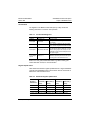
REGISTER UPDATE TIMES
Table 14 lists the maximum register update times for a single ATS46
controller using UNI-TELWAY protocol. These times assume a baud rate
of 9600 and no communication errors.
Table 14:
Maximum Register Update Times
Number of Registers
Transferred
Read Time [1]
(msec)
Write Time [2]
(msec)
1
44.7
43.5
10
65.3
64.2
20
88.2
87.1
50
157.0
155.8
[1]
Read is by “read object” (36H) request. Values shown include query
time, master processing time, and acknowledge (ACK) time.
[2] Write is by “write object” (37H) request. Values shown include query
time, master processing time, and acknowledge (ACK) time.
© 1998 Square D All Rights Reserved
35
ALTISTART 46 Communication Option
Chapter 3—UNI-TELWAY Protocol
36
Bulletin No. VD0C32S303A
October 1998
© 1998 Square D All Rights Reserved
Bulletin No. VD0C32S303A
October 1998
ALTISTART 46 Communication Option
Chapter 4—MODBUS Protocol
CHAPTER 4: MODBUS PROTOCOL
PRINCIPLE OF COMMUNICATION
MODBUS is a dialog protocol which creates a hierarchical structure
between a master device and one or several slave devices. The
ALTISTART 46 (ATS46) controller is always a slave device. MODBUS
protocol enables the master device to interrogate one or more intelligent
slaves. A multi-drop link connects the master device and slaves to one
another.
Two types of dialog are possible between master device and slave:
• The master device communicates to the slave and waits for a
response.
• The master device talks to a group of slaves without waiting for a
response (broadcast messages).
The slave number can be between 1 and 31. The number 0 is reserved
for a broadcast message.
In either type of dialog, the master device initiates and controls all
exchanges with the slaves. If an incorrect exchange occurs, the master
device reiterates the exchange and declares the slave absent if no answer
is received after a given time has elapsed. Only one device may transmit
on line at any time. A slave cannot initiate an exchange, nor is lateral
communication (i.e., slave to slave) possible. The master device's
programming must therefore be designed to interrogate a slave and send
the data received to another slave.
Master
Controller
Slave
J
Slave
K
Slave
L
Figure 17: MODBUS Protocol
© 1998 Square D All Rights Reserved
37
ALTISTART 46 Communication Option
Chapter 4—MODBUS Protocol
Bulletin No. VD0C32S303A
October 1998
NOTE: Register structures in the ALTISTART controller are of
UNI-TELWAY designation. When using MODBUS protocol, note the
following differences:
1. Reverse bit order—UNI-TELWAY protocol is hexadecimal, 0 to F,
where MODBUS protocol is from 16 to 1.
UNI-TELWAY
0
6
7
8
9
A
B
C
D
E
F
MODBUS
16 15 14 13 12 11 10
9
8
7
6
5
4
3
2
1
1
2
3
4
5
2. Address offset by 1—Add 1 to the UNI-TELWAY address to get the
proper MODBUS address.
WARNING
UNINTENDED EQUIPMENT OPERATION
There is a shift of 1 between the address in UNI-TELWAY and
MODBUS protocols. When using MODBUS protocol, add 1 to each
address listed in the parameter tables throughout this manual.
Failure to follow this instruction can result in death, serious
injury or equipment damage.
Accessible Data
The MODBUS protocol enables data (bits and words) to be exchanged
between the master device and several slaves. In each slave unit, bit
areas are defined for the master device to use when reading or writing
data. Input objects may only be read, whereas output objects may be read
or written.
38
© 1998 Square D All Rights Reserved
Bulletin No. VD0C32S303A
October 1998
ALTISTART 46 Communication Option
Chapter 4—MODBUS Protocol
Slave J
Slave K
Transmission
Table
MODBUS addressing
Input
Bits
Output
Bits
Input
Words
Reception
Table
User Program
Master
Controller
Output
Words
Slave L
Figure 18: Input and Output Data Objects
Exchanges
The master device always initiates data exchanges. The master device
waits for the slave's answer before transmitting the next message, thus
avoiding any conflict on the line. Operation in half-duplex is therefore
authorized.
Checking and Supervision
When two entities are communicating via asynchronous serial link,
control of exchanges between them must naturally include exception
messages, should exchange faults occur. A slave receiving an incoherent
message will report an exchange fault to the master device, which in turn
will determine whether to repeat the exchange.
© 1998 Square D All Rights Reserved
39
ALTISTART 46 Communication Option
Chapter 4—MODBUS Protocol
Bulletin No. VD0C32S303A
October 1998
Master
ATS46
Controller
Figure 19: Communicating Exchange Faults
MSTR BLOCK
Overview
When using a bridge multiplexer as shown in Figure 9 on page 10, the
Master (MSTR) function block can be used. The BM85 bridge/multiplexer
(bridge mux) operates as a MODBUS Plus node and provides four serial
ports that can be configured separately for the serial devices in your
application. BM85 models are available for RS-232, RS-485 or
MODICON MODBUS serial devices.
If you are not using a bridge mux but would like to use MODBUS
commands, consult the MODICON MODBUS Protocol Reference Guide,
part number PI-MBUS-300. (This document is available by fax-ondemand from Schneider Automation at 1-800-468-5342. Select option 3,
documents 3001 and 3002.)
PLCs that support MODBUS Plus communications have a special MSTR
instruction with which nodes on the network can initiate message
transactions. The MSTR function allows you to initiate one of nine
possible network communications operations over MODBUS Plus. Each
operation is designated by a code, as described in Table 15.
Table 15:
MODBUS Operations Codes
Operation
40
Code
Operation
Code
Write data
1
Read global database
6
Read data
2
Get remote statistics
7
Get local statistics
3
Clear remote statistics
8
Clear local statistics
4
Monitor peer cop status
9
Write global database
5
© 1998 Square D All Rights Reserved
Bulletin No. VD0C32S303A
October 1998
ALTISTART 46 Communication Option
Chapter 4—MODBUS Protocol
The read and write MSTR instruction blocks are discussed on page 42.
For more information, refer to the user guide, MODICON Ladder Logic
Block Library, part number 840 USE 101 00.
Inputs
The MSTR block has two control inputs (see Figure 20). When the input
to the top node is ON, it enables the instruction. When the input to the
middle node is ON, it terminates the active operation.
Outputs
The MSTR block can produce three possible outputs (see Figure 20). The
output from the top node echoes the state of the top input; i.e., it goes ON
while the instruction is active. The output from the middle node echoes the
state of the middle input; i.e., it goes ON if the MSTR operation is
terminated prior to completion. The output from the bottom node goes ON
when an MSTR operation has been completed successfully.
Enables selected
MSTR operation
Control
Block
Terminates active
MSTR operation
data
area
Operation terminated
unsuccessfully
MSTR
length
Operation successful
Operation is active
BCKM
First register
to capture
intermittent
errors
Figure 20: Block Structure
© 1998 Square D All Rights Reserved
41
ALTISTART 46 Communication Option
Chapter 4—MODBUS Protocol
Bulletin No. VD0C32S303A
October 1998
Top Node Content
The 4x register entered in the top node is the first of nine contiguous
holding registers that comprise the control block.
Table 16:
Control Block Registers
Register
Content
Displayed
Identifies one of the nine MSTR operations
First implied
Displays error status
Second implied
Displays length
Third implied
Displays MSTR operation-dependent information
Fourth implied
Routing 1 register (used to designate the address of the destination
node for a network message transaction)
Fifth implied
Routing 2 register
Sixth implied
Routing 3 register
Seventh implied
Routing 4 register
Eighth implied
Routing 5 register
NOTE: Before programming an MSTR instruction, an understanding of
routing path structures is required. For information about routing path
structures, refer to the user guide, MODBUS Plus Network Planning and
Installation, part number 890 USE 100 00.
Middle Node Content
The 4x register entered in the middle node is the first in a group of
contiguous holding registers that comprise the data area. This data area
is the source of data in operations providing the communications
processor with data (e.g., a write operation). The data area is the
destination of the data in operations acquiring data from the
communications processor (e.g., a read operation).
Bottom Node Content
The integer value entered in the bottom node specifies length; i.e., the
maximum number of registers in the data area. The length must be in a
range between 1 and 100.
Read/Write Operations
An MSTR write operation transfers data from a controlling device to the
drive controller. An MSTR read operation transfers data from the drive
controller to a controlling device on the network.
42
© 1998 Square D All Rights Reserved
Bulletin No. VD0C32S303A
October 1998
ALTISTART 46 Communication Option
Chapter 4—MODBUS Protocol
Control Block
The registers in the MSTR control block (the top node) contain the
following information in a read or write operation.
Table 17:
Control Block Registers
Register
Function
Displayed
Operation type
Content
1=Write; 2=Read
First implied
Error status
Displays a hex value indicating an MSTR error,
when relevant.
Second implied
Length
Write = number of registers to be sent to slave
Read = number of registers to be read from slave
Third implied
Slave device data area
Specifies starting register in the ATS46 controller
to be read from or written to. Note that 1 must be
added to starting register. For example, to start
with W4062, current, 4063 would be placed in the
third implied register.
Fourth–Eighth
implied
Routing 1–5
Designates the first through fifth routing path
addresses, respectively. The last nonzero byte in
the routing path is the destination device.
Refer to the user guide, MODICON Ladder Logic Block Library, part
number 840 USE 101 00, for more information.
Register Update Times
Table 18 lists the maximum register update times for a single ALTISTART
controller using MODBUS protocol. These times assume a baud rate of
9600 and no communication errors.
Table 18:
Maximum Register Update Times
Number of
Registers
Transferred
MODBUS ASCII
Read Time
(msec)
[1]
Write Time
(msec)
MODBUS RTU
[1]
Read Time [1] Write Time [1]
(msec)
(msec)
1
68
59
61
52
10
106
97
82
73
20
148
138
105
96
50
273
263
174
165
[1]
Values include query time, master processing time, and acknowledge (ACK) time.
© 1998 Square D All Rights Reserved
43
ALTISTART 46 Communication Option
Chapter 4—MODBUS Protocol
44
Bulletin No. VD0C32S303A
October 1998
© 1998 Square D All Rights Reserved
Bulletin No. VD0C32S303A
October 1998
ALTISTART 46 Communication Option
Appendix A—Function Index
APPENDIX A
Table 19:
Function Index Table
Code
Address [1] Page
C
Active on positive edge
CMD, INT
W4060,D
26
Control loop
F
Select closed loop (torque control)
open loop (voltage regulation)
CLP
W4035,0
25
Start
C
A
A
A
A
A
A
A
D
D
D
D
D
Run command
Acceleration ramp time
Initial torque during acceleration
Maximum torque during acceleration
Limit current
Boost level
Start time too long
Stator loss compensation
Controller ready
Steady state
Short-circuited
Current limited
Acceleration phase
CMD, RUN
ACC
TQ0
TLI
ILT
BST
TLS
LSC
ETA, RDY
ETA, 8
ETA, 9
ETA, LIM
ETA, B
W4060,5
W4043
W4037
W4036
W4039
W4028
W4033
W4027
W4061,1
W4061,8
W4061,9
W4061,D
W4061,B
26
24
24
24
24
25
25
25
27
27
27
27
27
Stop
C
C
C
C
A
A
A
A
D
Freewheel stop command
Decelerated stop command
Braked stop command
Control motor deceleration in cascade
Decel: deceleration ramp slope
final torque during deceleration
Braking: braking current
adjustment of braking time
Stop phase
CMD, CAL
CMD, CAD
CMD, CAF
DMC
DEC
EDC
BRC
EBA
ETA, A
W4060,8
W4060,7
W4060,6
W4060,3
W4044
W4038
W4041
W4042
W4061,A
26
26
26
26
24
24
24
24
27
Motor protection
C
A
A
F
D
Reset thermal state
Trip threshold (underload)
Motor nominal current
Motor thermal protection
Motor thermal state
CMD, RTH
TLS
In
THP
LTH
W4060,A
W4031
W4026
W4034
W4064
26
25
25
25
27
Description
Return to factory settings
Controller protection
Type Characteristics
Trip current threshold
OIL
W4040
24
Mains supply
F
D
D
D
Default assignment of phase rotation
Phase rotation state
No mains supply
Mains supply frequency
PHR
PHE
ETA, E
ETA, F
W4032
W4065
W4061,E
W4061,F
25
28
27
27
Measurements
D
D
D
D
D
Current
Cos (ϕ) motor power factor
Torque
Elapsed time meter
Reset elapsed time meter
LCR
COS
LTR
TFR
TRE
W4062
W4067
W4063
W4068
W4060,C
27
28
27
28
26
Special operation
F
C
Test on low power motors
Cascade motor operation
SST
CSC
W4035,5
W4035,6
25
25
Types:
[1]
F, A
C = Command
F = Configuration
A = Adjustment
D = Display
When using MODBUS protocol, add 1 to the address.
© 1998 Square D All Rights Reserved
45
ALTISTART 46 Communication Option
Appendix A—Function Index
Table 19:
Bulletin No. VD0C32S303A
October 1998
Function Index Table (Continued)
Code
Address [1] Page
Assignment of logic input LI
Assignment of logic output LO1
Assignment of logic output LO2
Assignment of analog output AO
Analog output scale
Analog output range
Assignment of relay R1
State of I/O: Logic input LI
Logic output LO1
Logic output LO2
Relay R1
Relay R2
Vigithem
Logic input LI_RUN
Logic input LI_STOP
Operating duty switch
Value of analog output AO
LI
LO1
LO2
AO
ASC
AO1
R1
LIO
I/O management
F
F
F
F
A
F
F
D
D
D
D
D
D
D
D
D
D
SAO
W4022
W4023
W4035,3
W4024
W4025
W4035,4
W4035,2
W4066
W4066,1
W4066,2
W4066,3
W4066,4
W4066,5
W4066,6
W4066,7
W4066,8
W4070
24
24
25
24
25
25
25
28
28
28
28
28
28
28
28
28
29
Communication &
terminal block
management
C
C
C
F
F
F
F
D
D
D
Assignment of online commands
Store adjustments in EEPROM
Recall adjustments from EEPROM
Product address
Protocol
Transmission speed
Character format
In local/line mode
Stopped after request via terminal block
Local control
DLI
MRE
RRE
ADR
PRO
SPD
FOR
LOC
ETA, 3
FLO
W4060,1
W4060,E
W4060,F
W2290
W2291
W2292
W2293
W4061,0
W4061,3
W4061,5
26
26
26
12
12
13
13
27
27
27
External fault command
Controller reset command
No time out SLF
Automatic reset
Controller faulted
Communication check inhibited
Current threshold alarm
Motor thermal alarm
Internal fault
Short-circuit fault
Phase inversion fault
Serial link fault
External fault
Start too long fault
Mains failure and start request fault
Phase fault
Controller thermal fault
Locked rotor in steady state fault
Motor thermal overload fault
Mains frequency fault
Underload fault
Time before starting alarm
EFL
RST
NTO
ARS
FAI
NTO
Fault and alarm
management
C
C
C
F
D
D
D
D
D
D
D
D
D
D
D
D
D
D
D
D
D
D
W4060,2
W4060,0
W4060,4
W4035,1
W4061,2
W4061
W4061,7
W4061,C
W4069,1
W4069,2
W4069,3
W4069,5
W4069,6
W4069,7
W4069,8
W4069,9
W4069,A
W4069,B
W4069,C
W4069,D
W4069,F
W4071,0
26
26
26
25
27
27
27
27
29
29
29
29
29
29
29
29
29
29
29
29
29
29
Fault history
D
D
D
Fault order
Fault register repetition
Time counter repetition
PTR
DFT
W4090
W4091
W4092
29
29
29
Description
Type Characteristics
Types:
C = Command
[1] When
using MODBUS protocol, add 1 to the address.
46
F = Configuration
A = Adjustment
OVL
INF
OCF
PIF
SLF
ETF
STF
USF
PHF
OHF
LRF
OLF
FRF
ULF
TBS
D = Display
© 1998 Square D All Rights Reserved
Bulletin No. VD0C32S303A
October 1998
ALTISTART 46 Communication Option
Appendix B—Function Index by Address
APPENDIX B
Table 20:
Function Index Table by Address
Address [1] Description
Type Characteristics
Code
Page
W2290
Communication & terminal
block management
F
Product address
ADR
12
W2291
Communication & terminal
block management
F
Protocol
PRO
12
W2292
Communication & terminal
block management
F
Transmission speed
SPD
13
W2293
Communication & terminal
block management
F
Character format
FOR
13
W4022
I/O management
F
Assignment of logic input LI
LI
24
W4023
I/O management
F
Assignment of logic output LO1
LO1
24
W4024
I/O management
F
Assignment of analog output AO
AO
24
W4025
I/O management
A
Analog output scale
ASC
25
W4026
Motor protection
A
Motor nominal current
In
25
W4027
Start
A
Stator loss compensation
LSC
25
W4028
Start
A
Boost level
BST
25
W4031
Motor protection
A
Trip threshold (underload)
TLS
25
W4032
Mains supply
F
Default assignment of phase rotation
PHR
25
W4033
Start
A
Start time too long
TLS
25
W4034
Motor protection
F
Motor thermal protection
THP
25
F
Select closed loop (torque control)
open loop (voltage regulation)
CLP
25
W4035,0
Control loop
W4035,1
Fault & alarm management
F
Automatic reset
ARS
25
W4035,2
I/O management
F
Assignment of relay R1
R1
25
W4035,3
I/O management
F
Assignment of logic output LO2
LO2
25
W4035,4
I/O management
F
Analog output range
AO1
25
W4035,5
Special operation
F
Test on low power motors
SST
25
W4035,6
Special operation
C
Cascade motor operation
CSC
25
W4036
Start
A
Maximum torque during acceleration
TLI
24
W4037
Start
A
Initial torque during acceleration
TQ0
24
W4038
Stop
A
Decel: final torque during deceleration
EDC
24
W4039
Start
A
Limit current
ILT
24
W4040
Controller protection
W4041
Stop
F, A
Trip current threshold
OIL
24
A
Braking: braking current
BRC
24
A
Braking: adjustment of braking time
EBA
24
W4042
Stop
Types:
C = Command
[1] When
using MODBUS protocol, add 1 to the address.
F = Configuration
© 1998 Square D All Rights Reserved
A = Adjustment
D = Display
47
ALTISTART 46 Communication Option
Appendix B—Function Index by Address
Table 20:
Bulletin No. VD0C32S303A
October 1998
Function Index Table by Address (Continued)
Address [1] Description
Type Characteristics
Code
Page
W4043
Start
A
Acceleration ramp time
ACC
24
W4044
Stop
A
Decel: deceleration ramp slope
DEC
24
W4060,0
Fault & alarm management
C
Controller reset command
RST
26
W4060,1
Communication & terminal
block management
C
Assignment of online commands
DLI
26
W4060,2
Fault & alarm management
C
External fault command
EFL
26
W4060,3
Stop
C
Control motor deceleration in cascade
DMC
26
W4060,4
Fault & alarm management
C
No time out SLF
NTO
26
W4060,5
Start
C
Run command
CMD, RUN
26
W4060,6
Stop
C
Braked stop command
CMD, CAF
26
W4060,7
Stop
C
Decelerated stop command
CMD, CAD
26
W4060,8
Stop
C
Freewheel stop command
CMD, CAL
26
W4060,A
Motor protection
C
Reset thermal state
CMD, RTH
26
W4060,C
Measurements
D
Reset elapsed time meter
TRE
26
W4060,D
Return to factory settings
C
Active on positive edge
CMD, INT
26
W4060,E
Communication & terminal
block management
C
Store adjustments in EEPROM
MRE
26
W4060,F
Communication & terminal
block management
C
Recall adjustments from EEPROM
RRE
26
W4061
Fault & alarm management
D
Communication check inhibited
NTO
27
W4061,0
Communication & terminal
block management
D
In local/line mode
LOC
27
W4061,1
Start
D
Controller ready
ETA, RDY
27
W4061,2
Fault & alarm management
D
Controller faulted
FAI
27
W4061,3
Communication & terminal
block management
D
Stopped after request via terminal block
ETA, 3
27
W4061,5
Communication & terminal
block management
D
Local control
FLO
27
ETA, 8
27
W4061,7
Fault & alarm management
D
Current threshold alarm
W4061,8
Start
D
Steady state
27
W4061,9
Start
D
Short-circuited
ETA, 9
27
W4061,A
Stop
D
Stop phase
ETA, A
27
27
W4061,B
Start
D
Acceleration phase
ETA, B
W4061,C
Fault & alarm management
D
Motor thermal alarm
OVL
27
W4061,D
Start
D
Current limited
ETA, LIM
27
W4061,E
Mains supply
D
No mains supply
ETA, E
27
Types:
[1]
48
C = Command
F = Configuration
A = Adjustment
D = Display
When using MODBUS protocol, add 1 to the address.
© 1998 Square D All Rights Reserved
Bulletin No. VD0C32S303A
October 1998
ALTISTART 46 Communication Option
Appendix B—Function Index by Address
Table 20:
Function Index Table by Address (Continued)
Address [1] Description
Type Characteristics
Code
Page
W4061,F
Mains supply
D
Mains supply frequency
ETA, F
27
W4062
Measurements
D
Current
LCR
27
W4063
Measurements
D
Torque
LTR
27
W4064
Motor protection
D
Motor thermal state
LTH
27
W4065
Mains supply
D
Phase rotation state
PHE
28
W4066
I/O management
D
State of I/O: Logic input LI
LIO
W4066,1
I/O management
D
Logic output LO1
W4066,2
I/O management
D
Logic output LO2
28
W4066,3
I/O management
D
Relay R1
28
28
28
W4066,4
I/O management
D
Relay R2
28
W4066,5
I/O management
D
Vigithem
28
28
W4066,6
I/O management
D
Logic input LI_RUN
W4066,7
I/O management
D
Logic input LI_STOP
28
W4066,8
I/O management
D
Operating duty switch
28
W4067
Measurements
D
Cos (ϕ) motor power factor
COS
28
W4068
Measurements
D
Elapsed time meter
TFR
28
W4069,1
Fault & alarm management
D
Internal fault
INF
29
W4069,2
Fault & alarm management
D
Short-circuit fault
OCF
29
W4069,3
Fault & alarm management
D
Phase inversion fault
PIF
29
W4069,5
Fault & alarm management
D
Serial link fault
SLF
29
W4069,6
Fault & alarm management
D
External fault
ETF
29
W4069,7
Fault & alarm management
D
Start too long fault
STF
29
W4069,8
Fault & alarm management
D
Mains failure and start request fault
USF
29
W4069,9
Fault & alarm management
D
Phase fault
PHF
29
29
W4069,A
Fault & alarm management
D
Controller thermal fault
OHF
W4069,B
Fault & alarm management
D
Locked rotor in steady state fault
LRF
29
W4069,C
Fault & alarm management
D
Motor thermal overload fault
OLF
29
W4069,D
Fault & alarm management
D
Mains frequency fault
FRF
29
W4069,F
Fault & alarm management
D
Underload fault
ULF
29
W4070
I/O management
D
Value of analog output AO
SAO
29
W4071,0
Fault & alarm management
D
Time before starting alarm
TBS
29
W4090
Fault history
D
Fault order
PTR
29
W4091
Fault history
D
Fault register repetition
DFT
W4092
Fault history
D
Time counter repetition
Types:
[1]
C = Command
F = Configuration
A = Adjustment
29
29
D = Display
When using MODBUS protocol, add 1 to the address.
© 1998 Square D All Rights Reserved
49
ALTISTART 46 Communication Option
Appendix B—Function Index by Address
50
Bulletin No. VD0C32S303A
October 1998
© 1998 Square D All Rights Reserved
Bulletin No. VD0C32S303A
October 1998
ALTISTART 46 Communication Option
Appendix C—Configuration with Windows 95 or Later Versions
APPENDIX C
If you have Windows 95, or a later version, to configure the ATS46
controller for MODBUS or UNI-TELWAY communications, first access the
HyperTerminal utility or a comparable Terminal Emulation Program.
Configure the COM port, terminal properties, and ASCII set-up as
illustrated in Figures 21 through 22.
Figure 21: Accessing HyperTerminal (Windows NT Example)
© 1998 Square D All Rights Reserved
51
ALTISTART 46 Communication Option
Appendix C—Configuration with Windows 95 or Later Versions
Bulletin No. VD0C32S303A
October 1998
Figure 22: Creating a New Connection
Figure 23: Selecting a COM Port
52
© 1998 Square D All Rights Reserved
Bulletin No. VD0C32S303A
October 1998
ALTISTART 46 Communication Option
Appendix C—Configuration with Windows 95 or Later Versions
Figure 24: Setting COM Port Properties
Figure 25: Selecting Emulation Type
© 1998 Square D All Rights Reserved
53
ALTISTART 46 Communication Option
Appendix C—Configuration with Windows 95 or Later Versions
Bulletin No. VD0C32S303A
October 1998
Figure 26: ASCII Set-Up
Figure 27: Sample Terminal Commands and ATS46 Responses
54
© 1998 Square D All Rights Reserved
Bulletin No. VD0C32S303A
October 1998
© 1998 Square D All Rights Reserved
ALTISTART 46 Communication Option
Appendix C—Configuration with Windows 95 or Later Versions
55
ALTISTART 46 Communication Option
Appendix C—Configuration with Windows 95 or Later Versions
56
Bulletin No. VD0C32S303A
October 1998
© 1998 Square D All Rights Reserved
Bulletin No. VD0C32S303A
October 1998
© 1998 Square D All Rights Reserved
ALTISTART 46 Communication Option
Appendix C—Configuration with Windows 95 or Later Versions
57
For MODICON/MODBUS support,
please contact Schneider
Automation at 1-800-468-5342.
Square D Company
8001 Hwy 64 East
Knightdale, NC 27545
(919) 266-3671
Square D and
are registered trademarks of Square D Company.
MICROSOFT and WINDOWS are registered trademarks of Microsoft
Corporation. MODBUS is a registered trademark and MODICON is a
trademark of Schneider Automation, Inc. ALTISTART is a registered
trademark and UNI-TELWAY is a trademark of Telemecanique S.A. or
its successor-in-interest, Schneider Electric S.A.
Electrical equipment should be serviced only by qualified electrical
maintenance personnel. No responsibility is assumed by Square D for
any consequences arising out of the use of this material.
Bulletin No. VD0C32S303A October 1998 Replaces VD0C32S303
dated September 1998 © 1998 Square D All Rights Reserved