1
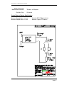
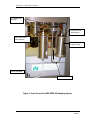
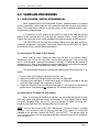
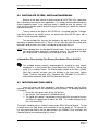
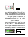
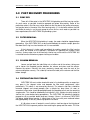
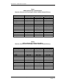
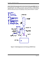
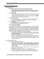
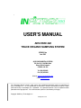
•
USER'S MANUAL
INFILTREX 300
TRACE ORGANIC SAMPLING SYSTEM
$
!" #
$%%& '
( " )$*$& + , % - . $'
,
/
%0 1
5' 01
23 4
23 4
3
Website: www.axystechnologies.com
e-mail: [email protected]
This Operations Manual contains trade secrets and confidential information, which are proprietary to
Axys Technologies Inc. Its use, reproduction, or disclosure in whole or part without the express written
permission of Axys Technologies Inc. is prohibited. This Operations Manual is also an unpublished work
protected under copyright laws. If this work becomes published, the following shall apply:
Copyright 2002 Axys Technologies Inc.
All Rights Reserved
MODEL IDENTIFICATION
The INFILTREX 300 is identified by a unique Serial Number. In any correspondence with
AXYS Environmental Systems always provide the INFILTREX 300 Serial Number.
This manual is supplied with, and is compatible with, the INFILTREX 300 and Watchman 300
serial numbers identified below.
Item
Serial Number/Version
INFILTREX 300
Location of Serial Numbers/Versions
The serial number for the INFILTREX 300 is stamped onto the top of aluminum frame.
INFILTREX 300 – USER’S MANUAL 0235801Z
CONTENTS
Page
1.0 INTRODUCTION ................................................................................................................................................1
1.1 DESCRIPTION AND FEATURES..................................................................................................................1
1.2 INFILTREX 300 SPECIFICATIONS ...........................................................................................................1
1.3 BASIC OPERATION......................................................................................................................................6
1.4 CARE OF INFILTREX 300 ...........................................................................................................................6
2.0 SAMPLING PROCEDURES............................................................................................................................8
2.1 XAD-2 COLUMN - INSTALLATION/REMOVAL .......................................................................................8
2.2 PARTICULATE FILTERS - INSTALLATION/REMOVAL..........................................................................9
2.3 INITIATION AND FINAL CHECK...............................................................................................................9
3.0 POST RECOVERY PROCEDURES .............................................................................................................11
3.1 PUMP DRY...................................................................................................................................................11
3.2 FILTER REMOVAL .....................................................................................................................................11
3.3 COLUMN REMOVAL .................................................................................................................................11
3.4 PREPARATION FOR STORAGE ...............................................................................................................11
4.0 COLUMNS.......................................................................................................................................................13
4.1 GENERAL.....................................................................................................................................................13
4.2 DEFINITIONS..............................................................................................................................................13
4.3 TRACE ORGANICS RESIN XAD-2 COLUMN .........................................................................................14
4.4 ELUTION OF TRACE ORGANICS RESIN I (XAD-2) COLUMN ...........................................................17
4.5 TRACE ORGANICS RESIN I (XAD-2) COLUMN STORAGE .................................................................17
4.6 TRACE ORGANICS RESIN I (XAD-2) COLUMN REUSE.......................................................................17
APPENDIX A...............................................................................................................................................................19
APPENDIX B .................................................................................................................................................................3
PAGE - iii
INFILTREX 300 – USER’S MANUAL 0235801Z
List of Tables
Page
Table 1.
PAHs in Distilled Water Experiments: Retention, Recovery and Trace
Organics Resin I (XAD-2) Column Efficiency ....................................................14
Table 2.
PAHs in Filtered Sea Water Experiments: Retention, Recovery and Trace
Organics Resin I (XAD-2) Column Efficiency............................................... 14
Table 3.
PCBs and Pesticides in Distilled Water: Retention, Recovery and Trace
Organics Resin I (XAD-2) Column Efficiency ............................................... 15
Table 4.
PCBs and Pesticides in Filtered Sea Water: Retention, Recovery and
Trace Organics Resin I (XAD-2) Column Efficiency ..................................... 15
List of Figures
Figure 1.
Figure 2.
Figure 3.
Side View of the INFILTREX 300 Sampling System ....................................... 4
Front View of the INFILTREX 300 Sampling System...................................... 5
Soxhlet Apparatus for the Cleaning of XAD-2 Resin..................................... 18
PAGE - iv
INFILTREX 300 – USER’S MANUAL 0235801Z
INFILTREX 300 is a second-generation instrument designed specifically for the
collection of samples of trace levels of organic impurities from large volumes of water. In
the absence of INFILTREX 300, large volumes of sample water are collected which then
require costly laboratory concentration before analysis can be done. INFILTREX 300
samplers are designed to remove the particulate and dissolved fractions in situ, and to
concentrate these during the sample collection process (hence INFILTREX: IN situ
FILTRation and EXtraction). Using INFILTREX 300 eliminates the need to collect, store,
and transport large volumes of water. The INFILTREX 300 allows for fast sampling flow
rates of up to 2250 mL/minute. The maximum sampling flow rates are determined by the
type of resin column/s chosen and the extraction efficiency for a given column size.
INFILTREX 300 is an operator actuated system requiring monitoring and
adjustment through the course of the sampling process. The 'basic system' as supplied,
consists of the main sampler, and several essential accessories. The basic system
consists of a NEMA enclosure (containing the pump and flow meter), and an electronic
control mounted on an aluminium frame. Further descriptions are detailed within this
manual.
The concentration process is accomplished by pumping the sample water through
an XAD-2 extraction column used to concentrate trace organic contaminants. AXYS
Environmental Systems pre-packs XAD-2 into several sizes of extraction columns. Empty
columns are available for users to fill with their own choice of materials.
The sample water feed is filtered before passing through the extraction column.
This prevents suspended particulate matter from interfering with the extraction process, and
allows separation of the dissolved from the suspended phase components. High capacity
cartridge filters are used where the sampled water volumes are large, or where water
sediment loads are high. Filters and holder components are easily removed for cleaning.
All materials used in the manufacture of the filter and column components have
been specifically chosen to be non-contaminating. Also, to assure integrity of the sample,
the components have been mechanically designed to be easily and completely cleanable,
Features
The INFILTREX 300 is a system that includes the following:
1. One INFILTREX 300 high volume trace organic sampling system
2. Two 4" SS Cartridge Filter Housings
3. One set of interconnection TFE/SS tubing for the attachment of 75g or 250 g SPE
columns
4. One set of manuals.
PAGE - 1
INFILTREX 300 – USER’S MANUAL 0235801Z
INFILTREX 300 Specifications
Overall Dimensions:
30” H * 17” W * 36” L
weight: ~110 lbs.
Materials:
All wetted parts in sampling stream, stainless steel or Teflon; all
instrument cases NEMA 4 rated
Sampling
Components:
Single or dual TFE resin columns or single SS large volume
columns;
filter housings (2) stainless steel;
filter elements: 4” glass wound with SS core.
Flow Measurement::
Optically sensed turbine flow meter, with redundant volumetric
logs (Watchman, Totalizer/rate meter); magnetic level switch.
Pumps:
#1- positive displacement, gear type (220VAC) with feed back
control from the flowmeter;
Flow Rates:
300 to 2,250 mL/min through resin columns; Long term average
within ± 3%, while the control loop is operating in its linear
range.
Total Volume:
± 3% at higher settings, ±10% at the 50 ml/min setting.
Power Supply:
Sampling System: 110 VAC mains, 750 Watts when pumping.
Control System:
Temperature:
Reliance Electric SP500 3PH Variable Frequency Motor
Controller.
-40 to +40 C (water must be non-freezing).
The system is designed to be operated directly by an operator.
Column Specifications
Physical Dimensions
(75 g or 250 g column):
Length:
Diameter:
6 in
1 in or 2.5 inches
Column Material:
Teflon or SS 316
Trace Organics I
(XAD-2):
Amberlite XAD-2 (A cross-linked polymer of styrene and
divinylbenzene synthesised with control of pore size, pore
size distribution and surface area. Amberlite XAD-2 is a
Trade Mark of Rohm and Haas Co., Philadelphia, PA).
PAGE - 2
INFILTREX 300 – USER’S MANUAL 0235801Z
Weight of Extraction
Material used in column:
End Mesh Size:
75 grams or 250 grams
210 micron
System Flow and Volume Specifications
Maximum Sample Rate 1.5 l/min
Maximum Sample Rate 0.5 l/min
based on SSLV 250 gram column
based on 75 gram TFE column
µ
µ
PAGE - 3
INFILTREX 300 – USER’S MANUAL 0235801Z
Filter Valves
Rate Meter Totalizer
Display
SP500 Pump
Motor Controller
Main Power Switch
ON/OFF
Sample Inlet
INFILTREX 300 Pump,
Power Supply and Flow
Meter Enclosure
Priming Valve
Sample Outlet
Figure 1. Side View of the INFILTREX 300 Sampling System
PAGE - 4
INFILTREX 300 – USER’S MANUAL 0235801Z
4” Cartridge Filter
Housings
Inlet face on new
column design
SSLV-250 Original
Column Design
SSLV-250_1 New
Column Design
Inlet to Flow Meter
Sample Flow Path
Figure 2. Front View of the INFILTREX 300 Sampling System
PAGE - 5
INFILTREX 300 – USER’S MANUAL 0235801Z
The INFILTREX 300 water sampler contains a pump whose flow rate can be
controlled, a flow accumulator system to measure total volume/rates pumped and a power
source (converts 110VAC to 220VAC).
The operator regulates the pump speed by manually adjusting the motor drive
controller (SP500) to increase or decrease the motor RPM. The resulting flow rates are
monitored on the Rate Meter/Totalizer installed on the upper bracket of the instrument.
The operator must determine the appropriate type of extraction material to use in
the column and the volume of sample water to be pumped. The flow rate chosen must be
slow enough to allow adequate water-to-extraction material contact to accomplish complete
extraction of the desired impurities, and yet fast enough so that an adequate total volume
can be sampled in a reasonable length of time.
If preloaded columns are purchased from AXYS Environmental Systems, they will
have been pre-cleaned. "Blank Certification" is available at additional cost. If columns are
being reused, or re-packed, they must be cleaned to the desired blank level. AXYS
Environmental Systems offers a cleaning and/or Blank Certification service, as well as
advice on cleaning or the use of columns. The inlet plumbing and filter components must
also be similarly cleaned to the operator's standards.
The pump is located in the sampler upstream from the column and filter. It is a
positive displacement gear. If the system is being used to sample at different sites, then
rigorous cleaning of the pump and filter housing system must be made to the same degree
of chemical purity as the column.
Do not pump harsh chemicals (acetone, hexane) which are incompatible with the
materials of the plumbing, pump and flow meter. The system can be flushed with methanol
to clean all wetted components without fear of damage.
Column and/or filter changes are required between consecutive samples taken in
the field. Only the operator can determine the quality of cleaning necessary for the filter and
plumbing components between such samples. Additional filter and plumbing components
are available from AXYS Environmental Systems so that the operator may install cleaned
sets to allow simple changes in the field.
INFILTREX 300 is constructed of aluminium, stainless steel, and various plastics materials that need little care. As with any instrument, INFILTREX 300 should be protected
from shock and abrasion during storage, transportation, and use.
Never allow sand, dust, dirt or pieces of column resin to enter the INFILTREX 300
plumbing itself. The clearances in the gear pump and flow meter are very small and will be
jammed or damaged by dirt. To reduce this possibility, a 140 micron screen element is
PAGE - 6
INFILTREX 300 – USER’S MANUAL 0235801Z
mounted on the inlet pipe of the INFILTREX 300. Always use the in-line filter when
pumping any fluid through the sampler. This filter should be removed and the screen
carefully back-flushed (or replaced) regularly to keep it clean. Do not allow matter to enter
the inlet pipe while this screen filter is off. There is no screen on the outlet and although it is
far more difficult for particles to enter there, it should be similarly respected.
INFILTREX 300 should not be left with stagnant water in its plumbing as organisms
will grow quickly and degrade the flow meter performance, often permanently. To allow the
system to be cleaned after a sample has been taken, the columns and filter(s) should be
removed promptly, capped, checked and stored. A cleaning kit consisting of connecting
plumbing is provided to facilitate cleaning. As soon as convenient, clean water should be
pumped through the plumbing to flush out the remaining sample water. This should be
followed by a 10% solution of methanol to sterilize the system and inhibit organism growth
in the little fluid that will inevitably remain. The INFILTREX 300 should be pumped as dry as
possible before being packed away.
If there is a chance of INFILTREX 300 being stored below freezing, it should have a
final rinse with pure methanol before being pumped dry so that any remaining liquid will not
freeze.
PAGE - 7
INFILTREX 300 – USER’S MANUAL 0235801Z
When shipped from AXYS Environmental Systems, prepared columns are packed
in clean sealed bags. When ready to install, remove the caps from the ends of the column
fittings. These caps will be used later to seal the column, so they should be stored in a noncontaminating, sealed package.
It is normal for a small amount of the alcohol or water buffer from the packing
process to be released when the end caps are removed. Always visually confirm the
integrity of the retaining screen in each end before installing the column on the instrument.
The INFILTREX 300 inlet and filter-to-column piping must have been previously
cleaned to the operator's satisfaction. Connect the fittings from the INFILTREX 300 tubing
to the column fittings using the following procedures.
(a) Connection Of The Xad-2 75 G Tfe Column
When ready to install, remove the caps from the ends of the column fittings.
Remove only the nut from the end fitting - not the whole column end. The column end,
which is also threaded, should not be removed in the field. It should only be removed to
change the resin. After all the tubing for the columns and filters are connected and aligned,
the tube fitting nuts should all be tightened securely, and checked.
follows:
The recommended method of installing and tightening these tube fitting nuts is as
1. Push the tube into the column end fitting hole until it seats.
2. Hold it there and turn the fitting nut onto the threads until finger-tight.
3. Pull back on the tube lightly. It should move roughly a millimetre and stop as the grip
inside the fitting nut drops into the groove on the tube.
4. Tighten the fitting nut 3/4 of a turn beyond finger-tight. It is not necessary or advisable to
tighten further. Over-tightening will damage the TFE threads of the column union.
(b) Connection Of The Xad-2 250 G SS Column
When all the tubing for the columns and filters are connected and aligned, the tube
fitting nuts should all be tightened securely and checked. This large capacity column makes
use of SS Swagelok fittings that are less prone to damage. To tighten the fitting nuts,
thread on finger-tight, then use a wrench to tighten half a turn more.
NOTE: There are two versions of the SSLV 250g columns. The latest version is a welded
unit that is not symmetrical and has only one end cap. This column has a flow path
indicated on the end caps, showing the “INLET” and “OUTLET”. The operator needs to
ensure that the columns are not mounted upside down, otherwise some of the solid phase
resin may be lost.
PAGE - 8
INFILTREX 300 – USER’S MANUAL 0235801Z
Because of the large volumes of water pumped by INFILTREX 300, a particulate
filter is absolutely necessary for most applications. It is strongly recommended for even the
cleanest appearing water. If any particulate matter is allowed to enter the column it will
soon coat the extraction material and either plug the flow totally or reduce the material's
extraction efficiency.
The only choice of filter type on INFILTREX 300 is a cartridge-type filter. Cartridgetype filtering elements for organic analysis are wound glass fibre with SS cores, with a
nominal 1 micron extraction capability.
The two cartridge filter housings are located on the top of the assembly and are
opened by completely loosening the 1” SS nut. This will allow the lower SS housing to be
removed in order to access the used 4” cartridge or to load a new filter unit.
NOTE: When reloading filters, the filter bowl will contain water. Care should be taken not to
spill particulate-laden water that is required for analysis. The recovered cartridge,
plus residual water, should be put into a clean glass jar for analysis.
a) Wound Glass Fibre Cartridge Filter Element (Part Number Filterite G1A4SE)
The cartridge element normally recommended for sampling for trace organic
compounds is a Heat Purified Glass Fibre Wound element with a 1 micron filter
rating. This is made by Filterite. The Filterite product number for this filter is 1A4SE.
Other filter materials and pore sizes are available in the same series. Contact
Filterite, Timonium, Maryland, USA, Telephone (301) 252-0800. The G1A4SE is
also available individually from AXYS Environmental Systems
Once the column and filter components have been assembled, and the fittings
tightened, the operator initiates the sampling by starting the pump. The pumping sequence
is started by:
turning the main power switch to the “ON” position.
pressing the “Start” button on the SP500 control unit.
The speed of the pump is controlled by pressing either the up arrow to increase
the RPM or the down arrow to reduce the RPM. The number displayed on the
unit is the motor RPM.
Three lights should be active in “Normal” sample mode: RPM, RUN and Forward”. To stop
a sample, press the “Stop” button on the controller or turn the power off. This control unit
has many advanced features that are documented in the SP500AC Drive Installation and
Operation Manual also accompanying this system.
PAGE - 9
INFILTREX 300 – USER’S MANUAL 0235801Z
Push to Start
Under ideal conditions the INFILTREX 300 is capable of dry lifting a 3m head of
sample water up the inlet line at maximum RPM. However, if the gears are slightly worn, or
if there is a fitting not completely sealed, then the dry lift capability is reduced. There is a
purge valve upstream of the inlet filter to allow the operator to prime the system plumbing
with clean water and fill the inlet piping and pump head prior to starting the sample. In
order to get maximum suction to start the pumping in a new location, the RPM may have to
be increased to maximum to establish flow, then monitoring the Totalizer/Rate Meter
reduce the pump RPM to the desired sample flow rates.
The Totalizer / Rate Meter is situated on the top of the sampler to allow for easy
operator access. This unit with display either the accumulated total volume or the
instantaneous flow rate. The units and time scale are all programmable features within this
module (refer to trouble shooting and service to change the display). The default
configuration delivered from Axys is:
Litres to 0.000
Flow rate is Litres (0.000) per minute
The operator resets the totalizer window to zero at the start of a sample event by
pressing the reset switch. Once the INFILTREX 300 is pumping, it is under the direct
control of the operator who can manually adjust the sample stream flow rates to the desired
values. There is a toggle switch on the display to change between the two modes:
Totalizer and Rate Meter.
CAUTION: If the reset switch is enabled, care must be taken not to press this switch when
in the Totalizer display or the current accumulated value will be reset to zero.
During the course of the sampling period, the operator should periodically check the
metered flow rates against a known volume per time in a graduated vessel to ensure the
accuracy of the systems performance.
Toggle between Totalizer and Rate
Totalizer Rest
PAGE - 10
INFILTREX 300 – USER’S MANUAL 0235801Z
There will still be water in the INFILTREX 300 plumbing and filter housing cavities.
As much water as possible should be pumped out before disassembly. Some of the
particulate matter in the filter may not be adhere to the filter due to the jostling of recovery,
and may be loose in the water in the filter housing cavity. If it is desired to recover the filter
and filtrate for analysis, run the main pump for a time until as much water as possible has
been expelled out of the INFILTREX 300 plumbing system.
When the INFILTREX 300 plumbing is empty, the motor should be stopped before
proceeding. If the INFILTREX 300 is to be used immediately for another sample, place the
filter bowl and O-ring in a clean location until it is reassembled.
If the instrument is to be used immediately for another sample, the filter housing
must either be cleaned to the operator's satisfaction or replaced with another clean
housing. A clean water rinse of the housing's interior may suffice until the INFILTREX 300
is returned from the field when a proper cleaning can be done.
Loosen and pull back the tube fitting nuts at either end of the column, taking care
not to loosen the threaded junction between the column end piece and the column.
Remove the column. Reinstall the clean, previously stored caps onto the ends of the
column and tighten securely. Put a label (or recheck the label) on the column and the filter
before storage.
INFILTREX 300 must not be stored with water in its plumbing cavities as organisms
may grow in the stagnant water and degrade the flow meter performance, often
permanently. This abuse is not covered by warranty. The columns and filters should be
removed, capped, and stored promptly after a sample has been taken. As soon as
convenient, clean water should be pumped through the plumbing to flush out the remaining
sample water. This should be followed by flushing with a 10% solution of methyl alcohol to
sterilize the system before being pumped dry. The INFILTREX 300 plumbing should be
pumped as dry as possible before long term storage. If there is a chance of INFILTREX
300 being stored below freezing, it should have a final rinse with pure methanol before
being pumped dry so that any remaining liquid will not freeze.
A 140 micron screen is located in a small stainless steel housing on the inlet pipe of
the INFILTREX 300 to prevent particles from reaching the pump and flow meter. This filter
PAGE - 11
INFILTREX 300 – USER’S MANUAL 0235801Z
should be removed and the screen carefully back-flushed, or replaced regularly, to keep it
clean. Beware of allowing matter to enter the inlet pipe while this screen filter is off. There is
no screen on the outlet and, although it is far more difficult for particles to enter there, it
should be similarly respected.
PAGE - 12
INFILTREX 300 – USER’S MANUAL 0235801Z
The column design is optimised for use with the INFILTREX line of
samplers. There are several sizes and types of SPE columns available (50g, 75g, and
250g). The ends of the column each have a screw on end piece, fitted with an internal
screen to retain the column contents. The end pieces are in turn threaded to connect to the
tube fittings on the INFILTREX assembly. When not in use, this thread is covered by a
standard screw-on cap fitting to protect the integrity of the contents.
Bulk resins are available from AXYS Environmental Systems, to allow users to
repack their own columns or to do laboratory experiments. These resins are cleaned,
sorted and are of the same high quality as found in the pre-packed INFILTREX columns.
XAD-2 resin may be cleaned and re-used until the blank levels become
unacceptably high.
The column may be disassembled for repacking by unscrewing the column end
pieces from the column tube, and emptying out the resin. Each end piece has a press fitted
screen to retain the resin. Removal of this screen from the end pieces should not be
attempted. If the screen is damaged, the column must be returned to AXYS Environmental
Systems for refurbishment.
The parameters used to describe column performance are the Retention Efficiency,
the Recovery Efficiency and the Column Efficiency.
The Retention Efficiency of a column is a measure of the ability of the column to
extract a trace pollutant from water. It is determined by passing a known amount of the
pollutant through a column and determining the amount retained by analysis of the input
and output.
Retention Efficiency =
(Input - Output )
Input
The Recovery Efficiency is a measure of the effectiveness of the elution process
used to recover a trace pollutant from the column. It is determined by eluting the retained
pollutant from the column and analyzing the eluate.
Recovery Efficiency =
(Amount Recovered)
(Amount on Column Prior to Elution )
PAGE - 13
INFILTREX 300 – USER’S MANUAL 0235801Z
The Column Efficiency is a measure of the overall performance of the column in
both extracting a pollutant effectively from water and permitting effective elution from the
column with solvent. Column efficiency is determined by obtaining the product of the
retention efficiency and the recovery efficiency.
Column Efficiency = (Retention Efficiency) X (Recovery Efficiency)
The column efficiencies of some elements and compounds, as determined through
experimental procedures, are given in the following sections.
(Part Number INAS0407, INAS0500, SSLV-250_1)
4.3.1 General
The Trace Organics Resin I (XAD-2™) column is designed for the extraction of
non-polar and moderately polar organic compounds from seawater or fresh water. The
column is filled with 50 to 250 g of Amberlite XAD-2 macroreticular resin packed in
methanol. This is a cross linked polymer of styrene and divinylbenzene synthesised with
control of pore size, pore size distribution and surface area. The first 200 to 1000 mL or so
of water that passes through the column will flush out the methanol and hence the trace
organics in this (very small) initial volume of water may not be fully extracted. This aspect
should be considered when the water volume passed through the column is small. The
column material is Teflon or Stainless Steel. The end screen is 297 micron size.
NOTE: XAD-2 is a trademark of the Rohm and Haas Co.
4.3.2 Trace Organics Resin I (XAD-2) Column Efficiency
A series of experiments determined the efficiencies of the Infiltrex Trace Organics
Resin I (XAD-2) Column for extracting a selected group of PAHs, PCBs, pesticides and
crude oil from filtered distilled and seawater. The results are summarized in Tables 1 to 4.
Calculated recovery efficiencies may exceed 100% when the blank levels and
sample concentrations approach the lower limits of detection. Under those conditions
experimental errors can be relatively large. Notice that in every case in which the column
efficiency appears to exceed 100%, the experimentally determined value is within a
standard deviation of 100%. Users are advised to determine the blank levels of each
column for the compounds of interest before using the column to concentrate real samples.
PAGE - 14
INFILTREX 300 – USER’S MANUAL 0235801Z
Table 1.
PAHs in Distilled Water Experiments:
Retention, Recovery and Trace Organics Resin I (XAD-2) Column Efficiency
Compound
Fluorene
Phenanthrene
Anthracene
Fluoranthene
Pyrene
Benz9a)anthracene
Chrysene
Benzo(e)pyrene
Benzo(a)pyrene
Retention (%)
100 ± 1
100 ± 1
100 ± 1
99.8 ± 0.1
99.7 ± 0.1
98.2 ± 0.5
93.9 ± 1.6
91.6 ± 1.0
87.5 ± 3.8
Column
Recovery (%)
85.5 ± 4.6
84.3 ± 4.1
84.4 ± 4.0
96.6 ± 5.3
96.0 ± 4.4
95.4 ± 10.6
92.6 ± 8.4
84.6 ± 6.6
97.7 ± 14.0
Efficiency (%)
85.5 ± 4.6
84.3 ± 4.1
84.3 ± 4.0
96.4 ± 5.3
95.7 ± 4.4
93.7 ± 10.4
86.9 ± 8.0
77.6 ± 6.1
85.5 ± 12.8
Table 2
PAHs in Filtered Sea Water Experiments:
Retention, Recovery and Trace Organics Resin I (XAD-2) Column Efficiency
Compound
Fluorene
Phenanthrene
Anthracene
Fluoranthene
Pyrene
Benz9a)anthracene
Chrysene
Benzo(e)pyrene
Benzo(a)pyrene
Retention (%)
100 ± 1
100 ± 1
99.6 ± 0.1
99.9 ± 0.1
99.8 ± 0.1
98.5 ± 0.1
94.7 ± 0.8
93.8 ± 1.2
91.4 ± 2.0
Column
Recovery (%)
93.8 ± 1.5
94.1 ± 0.9
97.4 ± 3.7
102 ± 6
102 ± 5
114 ± 14
134 ± 38
110 ± 19
112 ± 20
Efficiency (%)
93.8 ± 1.5
94.1 ± 0.9
97.0 ± 3.7
102 ± 6
102 ± 5
112 ± 13
127 ± 36
103 ± 18
102 ± 19
PAGE - 15
INFILTREX 300 – USER’S MANUAL 0235801Z
Table 3
PCBs and Pesticides in Distilled Water:
Retention, Recovery and Trace Organics Resin I (XAD-2) Column Efficiency
Compound
PCB
heptachlor
aldrin
o,p'-DDE
p,p'-DDE
lindane
heptachlor epoxide
trans chlordane
endosulfan
cis chlordane
dieldrin
DDD
endrin
DDT
methoxychlor
Retention (%)
90.5 ± 1.2
98.0 ± 0.1
97.6 ± 0.1
97.6 ± 0.2
96.2 ± 0.6
100 ± 1
99.6 ± 0.7
98.9 ± 0.1
100 ± 1
98.0 ± 0.1
100 ± 1
100 ± 1
100 ± 1
95.5 ± 0.4
100 ± 1
Column
Recovery (%)
100.5 ± 13.1
70.7 ± 4.5
77.2 ± 2.4
85.0 ± 4.5
96.1 ± 10.8
89.3 ± 11.9
83.0 ± 8.2
78.7 ± 8.3
76.3 ± 7.2
75.7 ± 3.9
81.8 ± 6.6
95.2 ± 13.7
82.2 ± 5.4
73.3 ± 5.0
90.8 ± 9.8
Efficiency (%)
91.0 ± 11.9
69.3 ± 4.4
75.3 ± 2.3
80.3 ± 4.4
92.4 ± 10.4
89.3 ± 11.9
82.6 ± 8.2
77.8 ± 8.2
76.3 ± 7.2
74.2 ± 3.8
81.8 ± 6.6
95.2 ± 13.7
82.2 ± 5.4
70.0 ± 4.8
90.8 ± 9.8
Table 4
PCBs and Pesticides in Filtered Sea Water:
Retention, Recovery and Trace Organics Resin I (XAD-2) Column Efficiency
Compound
PCB
heptachlor
aldrin
o,p'-DDE
p,p'-DDE
lindane
heptachlor epoxide
trans chlordane
endosulfan
cis chlordane
dieldrin
DDD
endrin
DDT
methoxychlor
Retention (%)
85.8 ± 0.2
98.9 ± 0.2
98.0 ± 0.1
93.9 ± 0.2
100 ± 1
100 ± 1
98.1 ± 0.2
100 ± 1
98.5 ± 0.1
100 ± 1
100 ± 1
100 ± 1
95.5 ± 0.6
100 ± 1
Column
Recovery (%)
71.9 ± 2.1
107 ± 19
91.0 ± 9.4
89.8 ± 2.6
102 ± 20
100 ± 5
101 ± 6
78.9 ± 9.9
95.3 ± 4.1
100 ± 6
113 ± 7
100 ± 7
80.3 ± 11.8
108 ± 12
Efficiency (%)
61.7 ± 1.8
106 ± 19
89.2 ± 9.2
84.3 ± 2.4
102 ± 20
100 ± 5
99.3 ± 5.9
78.9 ± 9.9
93.9 ± 4.0
100 ± 6
113 ± 7
100 ± 7
76.7 ± 11.3
108 ± 12
PAGE - 16
INFILTREX 300 – USER’S MANUAL 0235801Z
!
4.4.1 Procedure for the Elution of 50 g Columns
All elution solvents must be pesticide-grade or better to minimize contamination; all
glassware and inorganic materials must be free of interfering organics.
Using an elution apparatus the column is first eluted with 200 mL of methanol to
remove water. A second fraction is then collected by eluting with 200 mL dichloromethane.
The dichloromethane fraction is concentrated by rotary evaporation until only the residual
methanol (from the first elution step) remains.
The two fractions are then combined and their ionic strength is increased with
25 mL of a saturated NaCl solution that has been pre-extracted with hexane. The combined
fractions are back-extracted into 3 x 100 mL pentane. The pentane extract is then dried
over sodium sulphate and concentrated for analysis using standard analytical techniques.
An alternative procedure for eluting dioxins from XAD-2 resin with 15% acetone in
hexane has been developed by the Carleton University group.
4.4.2 Procedure for the Elution of 75 and 250 g Columns
All elution solvents must be pesticide-grade or better to minimize contamination; all
glassware and inorganic materials must be free of interfering organics.
The resin from the columns is removed and put into a soxhlet extraction apparatus.
"
!
Remove the column and replace the end caps. The column can then be stored for
up to three months prior to analysis with no special precautions. Columns should not be
frozen, as freezing can break down the extraction material and cause alterations in the
blank levels and the column performance.
If a filter has been used and is to be analyzed, it must be handled with solventcleaned metal tongs, wrapped in clean aluminum foil, and frozen until analyzed.
#
better.
!
All solvents used in cleaning columns and resins should be the pesticide-grade or
After elution, the Trace Organics Resin I (XAD-2) Column can be re-used after a
second rinse with 200 mL dichloromethane and a final rinse with 200 mL methanol. The
columns should be left moist with methanol and not be allowed to dry out, since drying may
cause the extraction material to crack. Columns can be cleaned and re-used until the blank
PAGE - 17
INFILTREX 300 – USER’S MANUAL 0235801Z
volume determined by the analysis of the rinse solvents becomes unacceptably high. The
columns can then be repacked with fresh XAD-2 by the user if laboratory facilities to clean
the packed columns are available. The columns may be cleaned on a modified Soxhlet
apparatus (Figure 3) with fresh dichloromethane. Alternatively, the column can be returned
to AXYS Environmental Systems for repacking or cleaning. Blank certification is available.
Figure 5. Soxhlet Apparatus for the Cleaning of XAD-2 Resin.
PAGE - 18
INFILTREX 300 – USER’S MANUAL 0235801Z
$$%&'()
Warranty and Service
PAGE - 19
INFILTREX 300 – USER’S MANUAL 0235801Z
WARRANTY
LIMITED WARRANTY
AXYS TECHNOLOGIES INC (“AXYS”) warrants that the
Equipment shall conform to Specifications and shall remain free
from defects in materials and workmanship for a period of twelve
(12) months from the date of delivery (the “Warranty Period”);
provided, however, that the Equipment is applied, installed,
operated and used substantially in accordance with the
Specifications.
AXYS shall, at AXYS' expense, replace or repair any Equipment
within such warranty period, provided:
AXYS receives written notice of any non-conformance or defect
within the Warranty Period;
after AXYS' authorisation, the Equipment is returned to AXYS'
factory of origin or to an Authorised AXYS Distributor with all freight
charges prepaid; and
AXYS determines the Equipment to have a non-conformance or
defect covered under this warranty.
Any replacement Equipment shall be warranted for a further period
that expires on the later occurrence of three (3) months from the
date of shipment or the expiration of the original warranty period.
LIMITATION OF LIABILITY
AXYS does not grant any further representations or warranties on
the Equipment than as expressly set forth above and expressly
disclaims all other warranties, express or implied, including any
warranties that the Equipment shall be merchantable, suitable or fit
for any purpose other than expressly stated. Notwithstanding any
other term of this Agreement, in no event shall AXYS be liable to
the Customer, its officers, employees, agents or contractors for any
lost or anticipated profits, for any incidental, consequential,
exemplary or special damages whether or not AXYS was advised
of such claim, or for damages and loss due to personal injury. In
any event, AXYS’ liability shall not exceed the purchase price of the
Equipment.
WARRANTY OF AUTHORITY
AXYS represents and warrants that it has full and complete power
and authority, corporate, legal and otherwise, to enter into and do all
things required to be performed or done under this Agreement; that
no litigation or other proceeding is pending or threatened against it,
and that no order or judgement or ruling has been made which
might adversely affect AXYS' right to enter into and do all things
required to be done under this Agreement.
WARRANTY OF INFRINGEMENT AND INDEMNIFICATION
AXYS represents and warrants that it owns and/or has legal right to
the hardware and software design, all applicable patents and other
intellectual and proprietary property, including without limitation all
patents, incorporated into, or to be used in connection with the
Equipment. AXYS further represents, and warrants that the design,
manufacture and sale of the Equipment, and the patents, patent
applications and other rights used in connection with the Equipment,
do not and will not infringe upon the patents, patent rights, copyrights,
trade secrets or other property interests of third parties. All royalties or
other charges for any patent, trademark or copyright to be used in
connection with the Equipment and/or Services shall be considered as
included in the purchase order price.
Notwithstanding any other provision contained in this Agreement,
AXYS shall defend, indemnify and hold the Customer, its affiliates,
directors, officers, agents, representatives and employees harmless
against any and all suits, proceedings, actions, claims, demands,
damages, losses, expenses or liabilities, in which it is claimed,
asserted or alleged, whether or not rightfully, that the Equipment,
Services, process, material or any part thereof, furnished by AXYS to
the Customer, constitutes an infringement of patent, patent application,
copyright, trade secret or other property interest of a third party, and
AXYS shall pay all damages, expenses (including reasonable
attorneys' fees) and costs awarded against or incurred by the
Customer or any third party to which the Customer is responsible in
connection therewith. In case the Equipment, process or material or
any part thereof is held in such suit action or proceeding to constitute
infringement and/or its use is enjoined or restricted, in addition to any
other rights and remedies the Customer may have hereunder or at law
or equity, AXYS shall, at its own expense, either procure for the
Customer an irrevocable, royalty-free, fully paid up license to continue
using the Equipment, process or material, or with the Customer’s' prior
written approval, replace the same with substantially equal but noninfringing Equipment or modify the Equipment so it becomes noninfringing, provided that no such replacement or modification shall in
any way amend or relieve AXYS or its warranties and guarantees set
forth in this Agreement.
The Customer shall give prompt notice to AXYS of any claim, suit or
proceeding involving the Customer in which such infringement is
alleged or asserted.
SERVICE
WARRANTY SERVICE
To obtain service under the warranty during the warranty period:
write, fax, e-mail or call AXYS Environmental Systems to describe
precisely and completely the nature of the problem;
carry out any minor adjustments or service as instructed by AXYS
technical personnel;
if proper operation is still not achieved, obtain an RMA (Return to
Manufacturer Authorisation) number from AXYS and return the
instrument, freight prepaid, to the factory or to an authorised Service
Centre. The instrument will not be accepted by AXYS without an
RMA. The instrument will be repaired and returned free of charge in
accordance with the terms of the warranty.
NON-WARRANTY SERVICE
As with Warranty Service, if the return of the instrument
is necessary, an RMA number must be obtained from
AXYS prior to shipping. The instrument must be
returned to the Company freight prepaid. Once the
instrument is received at the factory, a firm estimate of
the repair cost will be provided.
MODEL UPGRADES
Enhancements to the product will be made
from time to time. Whenever possible, earlier models of
the product may be upgraded at a reasonable cost to
provide the user with the new additional features and to
extend the useful life of the product. All registered
owners will be contacted when new design
enhancements are implemented.
Proceed as for Warranty Service described above. If AXYS
personnel can provide assistance by phone, letter, fax, or e-mail
they will be pleased to do so at no charge.
PAGE - 20
INFILTREX 300 – USER’S MANUAL 0235801Z
$$%&'()
Trouble Shooting and Service
INFILTREX 300 – USER’S MANUAL 0235801Z
Trouble Shooting and Routine Service
1. No water pumped:
a. Pump needs priming when dry to achieve more effective head suction.
i. Use the bypass line to prime the pump head with “clean” water.
ii. Fill the intake line with water to prime the pump, with a reduced overall head lift.
iii. Increase the pump RPM to get more suction, once flow is established reduce to
sample RPM.
b. Head height too high.
i. Need to reposition the sampling system closer to the water body to be sampled
such that the overall height to draw the sample is less than 3m. If the pumping
system cannot be relocated, then consider using an auxiliary submersible
pumping system to fill a clean reservoir to draw from.
c. Tubing resistance too high.
i. Too long of tubing run. If this cannot be reduced, then consider using an
auxiliary submersible pumping system to fill a clean reservoir to draw from.
ii. Diameter of tubing too small of diameter.
d. In line filter plugged.
i. Disassemble the inline filter and clean out the SS strainer.
ii. Check for foreign objects plugging the tubing inlet.
e. Cartridge filter elements plugged.
i. Change the filter element.
f. Pump gears are worn or damaged. For normal operations when using the inline filter,
the operator will be aware that the system will need to have progressively faster RPM’s to
maintain set flow rates. The gears can become damaged at any point if precautions are
not followed with inline prefilters installed. The MicroPump Service Kit S/K G132/G152,
MicroPump PN 83206 is required when doing any work on the pump head. Follow the
service kit instructions for replacement of any pump components.
i. Gear replacement can be done by simply removing the three screws securing the
top of the pump head. The gears are just pulled out and replaced the same way.
Replace the Teflon gasket.
ii. Inspect the top and bottom SS surfaces for any excessive wear.
iii. Once the replacement gears are installed check for any excessive free play on
the shafts. If this is discovered, then the bushings need to be replaced. This will
likely involve some disassembly of the pump head from the motor and is not
easily done in the field.
2. Rate Meter Totalizer Display:
a. Flow rate/Totalizer readings are incorrect.
i. The rate meter has been programmed with incorrect coefficients. Set the Rate
Meter/Totalizer to program mode. Check the coefficients provided with the
system as delivered. Refer to the McMillian Model 220 Operating Manual for
setup procedures. There is a software program provided to calculate the
coefficient settings.
ii. A new flow meter has been installed without the new coefficients being
programmed. Refer to step 2-a-i.
iii. The flow meter is defective. Replace the unit with a McMillian 101-8T.
iv. Check that signal and power cables are all connected to the flow meter in the
pump box and power supply. Same goes for the external Rate Meter/Totalizer.
INFILTREX 300 – USER’S MANUAL 0235801Z
v. The flow meter is not getting 12VDC power. With a volt meter check the power
supply for 12 VDC when the system is powered. CAUTION should be observed
when using probes on the power supply as 110 VAC is exposed in this area.
vi. If there is no display on the Rate Meter/Totalizer then the lithium battery in this
unit must be replaced.
b. Want different Rate Meter Totalizer Display Units .
i. Following the instructions as directed by the McMillan Model 220 Digital Rate
Meter and Totalizer Operating Manual, the operator can reprogram these default
display values to other units and time bases. To accomplish this the operator
needs to activate the Rate Meter programming switch located in the pump
enclosure. Once the Rate Meter is in “program mode”, other coefficients and
configuration setting can be set to change the display output.
ii. If a new flow meter has been installed, then the new calibrated flow meter
coefficients need to be programmed into the rate meter. Use the software
provided from McMillan to calculate the coefficients and unit/rate display output.