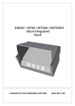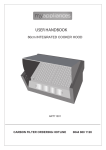
1
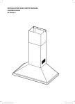
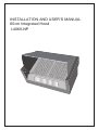
INSTALLATION AND USER’S MANUAL
60cm Integrated Hood
I-4060-NP
I
II II
0 I
2.
Contents.
Environmental Notes
Safety Instructions
Dimensions
Electrical Requirements / Installation
Installation continued / Fitting the Décor Panel
Extraction or Recirculation Mode
Accessories
Using Your Cooker Hood / Technical Data
Maintenance & Troubleshooting
.ENVIRONMENTAL PROTECTION
Waste electrical products should not be disposed of with household waste.
Please recycle where facilities exist. Check with your Local Authority or
retailer for recycling advice.
. Safety Instructions.
3.
Children should be supervised to ensure that they do not play with the appliance.
This appliance is not intended for use by persons (including children) with reduced physical,
sensory or mental capabilities, or lack of experience or knowledge, unless they have been
given supervision or instruction concerning the use of the appliance by a person
responsible for their safety.
This appliance must be disconnected from the electricity supply before carrying out
maintenance, to avoid any possibility of electric shock.
Flambé cooking is prohibited underneath this appliance.
This appliance is designed for domestic use only and cannot be installed for external use.
This appliance must not be installed below 66cm above a cooking hob, that is designated in
the installation instructions.
The exhaust from this appliance must never be discharged into any heating flue, which may
carry combustion products from another source i.e. boiler flue.
Exhaust air must not be discharged into a wall cavity, unless the cavity is designed for the
purpose.
There must be adequate ventilation of the room when the appliance is in use at the same
time as appliances burning gas or other fuels.
When this appliance is in use do not leave gas burners lit without covering the flame with a
pot or pan. Always turn off gas burners before you remove pots or pans.
If the supply cord is damaged, it must be replaced by the manufacturer, its service agent or
similarly qualified persons in order to avoid a hazard.
Caution! Accessible parts may become hot when used with cooking appliances.
Means for disconnection must be incorporated in the fixed wiring in accordance with the
wiring rules. To achieve this install appropriate switched fused connection unit.
An all-pole disconnection switch having a contact separation of at least 3mm in all poles
should be connected in fixed wiring.
4.
. Integrated Cooker Hood Dimensions.
Fig 1
Fig 2
59
9
D
C
10
M
370
522
N
205
L
120
L
P
522
100
Fig 3
40
0
12
0
12
2
340
1
270
B
1
2
E
5.
.Electrical Connection.
Before connecting the mains supply ensure that the mains voltage corresponds to the voltage on
the rating plate inside the cooker hood.
WARNING: THIS APPLIANCE MUST NOT BE EARTHED.
The cooker hood is supplied with a 2-core mains cable and must be connected to the electricity
supply via a double pole switch having a 3mm minimum contact gap on each connector. A
Switched Fused Connection Unit to BS 1363 Part 4 is a recommended.
The wires in the mains lead are coloured in accordance with the following UK code:
Brown = L - Live
Blue = N - Neutral
Brown
Brown
The connection point must be placed in a position adjacent to the appliance so as to be readily
accessible for an engineer in the event of a breakdown.
Disconnect the cooker hood from the mains supply before carrying out any kind of
maintenance or cleaning.
. Installation
Before installing this cooker hood it must be decided whether to use it in extraction mode or
recirculation mode. See page 7 for a description of the differences between the two modes.
If it is decided to use it in extraction mode any masonry work must be completed prior to fitting the
cooker hood and the electrical connection installed.
Mounting Height.
The bottom of the cooker hood should be no less than 650mm above an electric hob,
750mm above gas hob or mixed fuel cooker. For the best results the hood should be
mounted as near as possible to the minimum recommended height.
Mounting of the Cooker Hood Between Two Hanging Cupboards
Open the front panel and push the two catches (A) upwards and
remove the grille and grease filter.
II III
0 I
Pull the locking pin B, on both sides of the front panel, until they
stop, and pull the front panel forward until it is released from its
guide rails.
II III
0 I
A
6.
.
III
0 I II
B
Drill 2 holes on the side of the hanging cupboards as shown. The
thickness of the outer décor panel must be taken into consideration
so that when it is installed it remains at the same level as the side
hanging cupboard doors.
59
9
D
Fix the cooker hood to the side cupboards using 4 screws that are
appropriate to the type of cupboard.
To close the gap between the cooker and the wall loosen screws P
and slide the spaced L backwards until it touches the wall and tighten
the two screws.
C
205
120
L
100
P
Mounting of the Cooker Hood on the wall.
Drill 4 holes, 2 holes at position M and 2 holes at position N and
insert expanding plugs appropriate to the type of wall construction.
10
Fix the spacer L to the wall at the correct height.
M
370
522
N
Fix 2 screws at position M and hang the cooker hood onto the
screws. Adjust the hanging clamps so that the cooker hood rests
onto the spacer L. Tighten the hanging clamp screws and spacer
screws P.
L
522
. Fitting the Décor Panel.
40
0
12
Before refitting the front panel E the outer décor panel must be fitted.
Fix the décor panel as per the illustrated dimensions. Refit the front
panel by inserting it in the upper and lower slide guides. Pull the
locking pins out until they stop and close the outer door until locking
pins B click into position.
0
12
2
1
Note: It is important that if the locking pins are not pulled out until
they stop, and the outer door is forced into the slide guides, the
pins could be damaged or broken.
E
B
2
1
7.
. Extraction Mode or Recirculation Mode
Your new cooker hood can be installed either for recirculation or extraction through an outside wall. NOTE:
The cooker hood is more efficient in the extraction mode.
Installation for Recirculation.
If it is not possible to exhaust through an outside wall the cooker hood can
be fitted with a carbon filter (not supplied) to remove any odours and the
air is then re-circulated.
Installation for Extraction.
Fumes and greaseladen air are drawin into the cooker hood and
expelled outside the room.
The size of the ventilation pipe, (not supplied), must have a minimum diameter of 120mm and should not be longer than 3 meters.
150
150
Keep exhaust flue as short as possible.
Do not reduce the internal diameter of the exhaust flue throughout its full length.
Keep bends in the exhaust flue to a minimum.
When using a flexible flue always install the duct with the helix pulled taut to minimise pressure
loss.
Failure to observe these basic instructions will drastically reduce the performance and increase
the noise level of the cooker hood.
To fit the extraction pipe insert the vent collar D, (this can be found inside the cooker hood when it
is unpacked), into the aperture C on the top of the cooker hood and secure the pipe to the collar.
Important: The exhaust air must not be expelled through a smoke or waste gas chimney,
which is in use, or through a shaft used for ventilating rooms or into the cavity of a wall.
If the room contains a fuel burning appliance, such as a gas, or oil fired, central heating
boiler, which is not of the ‘Balanced Flue’ type, you should make sure that there is
adequate air inlet into the room at all times so that fumes from the boiler are not drawn
back into the room by the Cooker Hood.
. Accessories.
Description
Collar
E14 9W Lamp
Grease filter
8.
9.
. Using Your Cooker Hood.
The light and the fan motor will not operate if the outer cover is in the closed position.
Pull open the outer door and the control switches can be seen on the left side
panel. The upper slider switch will turn the lamps on and off. The lower slider
switch will turn the extractor fan motor on and off. There are three motor
speeds available.
I
II
III
Switching light on/off
Lower speed.
Medium speed.
High speed.
0 I II III
If the outer door is closed without switching off the fan motor, or lamps, an override switch will turn
the cooker hood OFF. When the outer door is opened the cooker hood will resume working at its
previous settings.
The cooker hood will not operate when the outer door is opened if the switches are in the
OFF position.
To obtain the best results from your cooker hood it is recommended that you switch on the fan
motor 10 to 15 minutes before you start cooking and leave it switched on for 15 minutes after you
have finished.
Your cooker hood is designed to extract odours and grease-laden air from the room. It is
not designed to remove steam.
Before using your cooker hood for the first time it should be cleaned using a soft cloth, with warm
soapy water. Do not use any type of abrasive detergents. Thoroughly dry the cooker hood.
To keep your cooker hood in pristine condition it should be cleaned regularly.
NOTE: Always disconnect the electricity supply before you commence cleaning, or any form of
maintenance.
Bulb Replacement.
II III
0 I
• Switch the appliance off and disconnect the power supply.
• Open the front panel amd push the two catches (A) upwards
and removed the grille and grease filter.
• Pull the locking pin B, on both sides of the front panel, until they
stop, and pull the front panel forward until it is released from its
guide rails.
A
• Screw the light bulb from the holder and replace by new light bulb
of the same type, max. 40W (E14).
• Replace the grille and front panel and make sure it locks in place.
B
III
0 I II
Power supply : 220-240V~ 50Hz
Power consumption – Fan : 125W
Power consumption – Luminary : 1 x 40W
Power consumption – Total : 165W
Protection class : II
Light bulb : Max. 40W (E14)
II III
0 I
. Technical Data
. Maintenance and Troubleshooting
Lamps fail to operate
10.
A replacement is possible necessary, but first check that the
lamp is correctly fitted into its holder. Remember that the
lamps are not covered by our guarantee. Remember to
disconnect the mains electricity supply before replacing the
lamps. Replace any failed lamps with the same type – E14
40 Watts Maximum.
Motor is on but the fan does not Check the grease filter. If it has not been cleaned recently, it
seem to be as efficient as usual might be clogged with grease. Remove it and soak it in hot
water and washing up liquid for about an hour. Rinse
thoroughly in hot water and allow it to dry before refitting it.
The grease filter should be cleaned every 2 months.
NOTE: The aluminium panel grease filter may alter in colour
after several washes. This is not cause for concern or
replacement of the filter.
If the cooker hood is being used in recycling mode the
carbon filter may be saturated. If it has not been replaced for
4 months remove it and insert a new one.
Appliance does not work at all
Check that your cooker hood is switched on at the mains.
Check that the fuse has not blown. Next, check that there is
power to your home by switching on adjacent lights.
Open the front panel, by pulling it towards you, and check
that the fan motor switch is switched to one of the 3 speed
settings.
Still not working?
service agent
Call
the If, having consulted the above diagnostic chart you are still
unable to remedy the situation, please contact our Call
Centre: 0844 800 1128.
.GUARANTEE.
Your 2nd Year Guarantee
Your appliance carries a 24 months parts and labour warranty. To fulfil the conditions of your
guarantee, the appliance must be correctly installed and operated, in accordance with the instructions, and only be used for normal domestic purposes.
Please note that the guarantee and
service availability only apply to the United Kingdom and the Republic of Ireland.
Customer Service
In case of difficulty please call the Customer Service Helpline on our helpline number.
0844 8001128
When calling customer service, please ensure you have the model and serial number to hand.
Please keep your receipt or invoice in a safe place as they will be required as proof of date of
purchase.