1
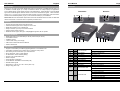
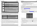
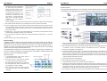
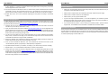
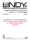
HDMI Video Wall over IP Extender
User Manual
English
No.38132
No.38133
Transmitter (TX)
Receiver (RX)
www.lindy.com
Tested to Comply with
FCC Standards
For Home and Office Use!
© LINDY Group - LINDY ELECTRONICS LIMITED & LINDY-ELEKTRONIK GMBH - FIRST EDITION (FEBRUARY 2015)
User Manual
English
Introduction
User Manual
English
Overview
Thank you for purchasing this LINDY HDMI Video Wall over IP Extender. This HDMI Extender allows you
to distribute an HDMI signal up to 1080p via Ethernet network to multiple displays for applications
such as digital signage, public display and large scale presentations. These extenders convert the HDMI
signal to IP broadcast signals. Network devices can be used to distribute the signals. These extenders
support 1-to-1, 1-to-many, many-to-many and video wall (2x2 up to 8x8) configurations, with Transmitters
and Receivers available separately to give you the maximum flexibility in your installation.
Transmitter
T4 T10 T3 T2
Receiver
T1
R4 R10 R3 R2
R1
Please Note: Because of bandwidth requirements these video broadcasts should use their own dedicated
network connections or should be used in a separate port based VLAN.
Features
•
•
•
•
•
•
Supports Unicast, Multicast and Video Wall modes
Video Wall mode supports screen arrays from 2x2 to 8x8
HDMI signal extension over a Gigabit LAN
Ability to cascade up to 3 layers of network switches
Features Video Tearing correction
HDMI with HDCP support, 480p up to 1080p60@8bit supported, 3D not capable
Package Contents
•
•
•
•
•
•
HDMI Video Wall over IP Transmitter (No. 38132) or Receiver (No. 38133)
2x Installation bracket
Installation screws
12V DC Multi-country power supply
LINDY Quick Install Guide and User Manual
Generic Software CD
T5
T6 T7 T8
T9
R5
R6
R7 R8
R9
Specification
•
•
•
•
•
•
•
•
•
•
•
•
Supports 4 Transmitters per IGMP equipped Gigabit Hub or Port Based VLAN
Transmitters and Receivers are paired using a 16 selection rotary switch
Each Pairing can be broadcast to up to 1000 Receivers
HDTV resolutions: 720p to 1080p @ 60Hz
PC Resolutions: XGA to WUXGA (1200p)
Supports 2 CH LPCM HDMI Audio
HDCP Compliant
Automatic EDID configuration
Control Method: Serial RS232 or Web GUI (LAN)
Extends RS232 signals
Dimensions (H x W x D): 25 x 96 x 130mm (each unit)
Weight: 500g (each unit)
T1
R1
Video Connector
Connect to the HDMI Source
Connect to the HDMI Monitor
T2
R2
RJ45 Socket
Connect to a Gigabit Hub
T3
R3
Reset Button
Reboots the unit
T4
R4
Power Supply
T5
R5
F2 Push Button
T6
R6
F1 Push Button
T7
R7
Rotary Switch
Set pairing values
T8
R8
Serial Port 1
For system control
T9
R9
Serial Port 2
T10
R10
Network Status LED
Please see the Function Button section
For data communication
Flashing: Connected to a network
Off: No network connection
Green: No Link with Receiver
T11
Blue: Linked to Receiver
Power/Link LED
R11
Flashing Blue & Green: Linked but no input video signal
Red: No Link with Transmitter
Blue: Linked to Transmitter
Flashing Blue &Red: Linked but no input video signal
User Manual
English
Function Button Control
F1
Tx
F2
Reset
F1
Rx
F2
Reset
Link/Unlink Video (Applies to all Tx & Rx of the same pairing value) – Press Once
Factory Reset/Default – Power the unit off >Press and hold the button> power the
unit on > after 17 seconds release the button (the Power/Link LED will flash Green &
Blue > power the unit on again
Select Graphic/Video Mode (Applies to all Tx & Rx of the same pairing value) –
Press for 1 second. (Factory Default is Graphic Mode)
Anti-Dither Adjustment Mode: Level 1, Level 2, Off (Applies to all Tx & Rx of the
same pairing value) – Press and hold for 3 seconds (Factory Default is Off)
Reboot the unit – Press once
Link/Unlink Video (Applies to all Tx & Rx of the same pairing value) – Press Once
Factory Reset/Default – Power the unit off >Press and hold the button> power the
unit on > after 17 seconds release the button (the Power/Link LED will flash Red&
Blue > power the unit on again
Select Graphic/Video Mode (Applies to all Tx & Rx of the same pairing value) –
Press for 1 second. (Factory Default is Graphic Mode)
Anti-Dither Adjustment Mode: Level 1, Level 2, Off (Applies to all Tx & Rx of the
same pairing value) – Press and hold for 3 seconds (Factory Default is Off)
EDID Copy – Power the unit off > press and hold the button > power on the unit >
after 12 seconds release the button (the Network Status LED will flash yellow) >
power the unit on.
Reboot the unit – Press once
Installation
User Manual
English
1. Connect the Transmitter(s) to your source and the Receiver(s) to your display using HDMI cables.
2. Connect the Transmitter(s) and Receiver(s) to your network using standard CAT5e UTP or higher
3. Set
cable.
the Rotary Switch of Transmitter(s) and Receiver(s):
a. 1-to-1 the Transmitter and Receiver must use the same value
b. 1-to-many the Transmitter and all Receivers must use the same value
c. Many-to-many Each Transmitter must use a different value; each group of Receivers must use
the same value as the Transmitter they are to connect to.
4. Power on all your devices
5. If you are using the Extender in Unicast or Multicast configuration on a dedicated network no further
steps are required
Video Wall Configuration
To set up the Video Wall you will need to access the Web GUI of Extender, to do this use the following
instructions using either Chrome or Safari web browsers. If you are using Chrome, please first install the
Bonjour SDK from http://developer.apple.com/opensource.
For the best video wall results we strongly recommend using the same make and model of display
throughout your installation.
1. Configure the PC you are using for control’s network setting to 169.254.xxx.xxx with a net mask of
255.255.0.0. (xxx can be any value from 0 – 255)
2. Open your web browser and enter the address http://ast-gateway0000.local, the four digits after astgateway depend upon the selection you have made with the Rotary Switch, in the example above the
Rotary switch is set to 0. Please refer to the table (below) for the Rotary Switch values and
corresponding four digit codes.
Please Note: Because of bandwidth requirements the HDMI Extenders should use their own dedicated
network connections or should be used in a separate port based VLAN, below is a table with the required
Ethernet Hub specification required for each configuration:
0
0000
8
0001
1
1000
9
1001
2
0100
A
0101
3
1100
B
1101
4
0010
C
0011
5
1010
D
1011
Configuration
Ethernet Hub Requirement
1-to-1 & 1-to-many
Gigabit Ethernet Hub
Many-to-many
Gigabit Ethernet Hub with IGMP & Snooping function
6
0110
E
0111
Video Wall
Gigabit Ethernet Hub with IGMP & Snooping function
7
1110
F
1111
Multiple Video Wall
Gigabit Ethernet Hub with IGMP, Snooping & VLAN functions
In Unicast configuration the Extender can be used with the Transmitter and Receiver directly connected
or connected via a Gigabit network. When the Extender is connected to a Gigabit network it is possible to
use up to 4 pairs of Transmitter and Receiver simultaneously by setting a different value on the Rotary
Switch for each Transmitter and Receiver pairing.
In Multicast and Video Wall configuration the Transmitter and Receivers are connected via a Gigabit
network. A Transmitter can be paired to multiple Receivers, by using the same Rotary Switch value on all
units. You can use up to 4 Transmitters which are paired with different groups of Receivers by using a
different Rotary Switch value on each Transmitter and then setting the Rotary Switch on each group of
Receivers accordingly. To configure the Video Wall the Web GUI is used to determine the size and layout
of the video wall and to make bezel edge adjustments, these functions are covered in the nextsection the
manual.
Before beginning the installation please ensure that all devices are powered off.
3. You will now see the Web GUI, click on Video Wall Setup and you will be presented with the Basic
Setup screen where you can adjust Bezel and Gap Compensation, as well as determining the size and
layout of your Video Wall:
4. Measure the Outer Width (OW), Outer Height (OH), View Width (VW) and View Height (VH) of your
display and enter these values into the corresponding fields of the Bezel and Edge Compensation
screen. Please Note: Values are expressed in units of 0.1mm and must be integer. If you do not require
Bezel Adjustment then set all values to 1.
5. Set the Vertical and Horizontal Monitor Count boxes to match your requirement. The minimum for each
field is 1, whilst the maximum is 8, allowing you to configure a 1x2, 2x2….up to 8x8 video wall.
6. Check the Single Host Mode box
7. Ensure that the Apply to drop down is set to all and then click Apply; you will see your displays begin
to refresh.
User Manual
English
8. To set the location within the video
wall that each screen will populate
you must assign each Receiver a
Column and Row position, via the
Wall Size and Position Layout menu.
The example shown here is for a 2 x
2 video wall. The top Row is 0, the
bottom Row 1, the left Column 0 and
right Column 1. In larger video walls
these Column and Row value will
increase by 1 for each additional
Column and Row.
User Manual
English
5. If required repeat steps 2 – 4 until the tearing has been removed.
Hardware Solution
The following example is based on a 4 x 4 video wall, to use the hardware solution for this example
4 Transmitters and a HDMI Splitter will be used instead of a single Transmitter as shown below.
Single Transmitter
Set Up
Start by setting both the Row and Column Position to 0, this will set the location as the top left display.
9. Now check the Show OSD tick box, your displays will now show a number via their OSD.
10. Click on the Apply to drop down menu and you will see a list of Clients in the format 0: 169.254.xxx.xxx,
where the leading number is the same as those used on the OSD and the IP address that of the
connected Receiver. Select the display you want to use in the Column and Row location you have set
above and click Apply.
Multi Transmitter Set Up
11. Repeat steps 8 – 10 for each of the locations/displays in your video wall, using the different Column
and Row values and displays to make up your video wall.
12. If you are setting up multiple video walls from a single Transmitter then repeat steps 4 – 10 for each
video wall.
13. When finished uncheck the Show OSD tick box.
Advanced Setup
In addition to the Basic Setup menu an Advanced Setup menu exists to allow users to make fine
adjustments to a row, column or all displays and to help overcome Screen Tearing issues.Screen
tearing may occur when the video feed to the device isn't in sync with the display's refresh or
because of a lack of sync between two equal frame rates. During video motion, screen tearing
creates a torn look as edges of objects fail to line up.
The simplest action to take to try to overcome screen tearing is to reduce the input resolution, but
this may not always be desirable, so using the Extender it is possible to address tearing via the
Web GUI, or by the use of additional hardware.
Web GUI Solution
1. In the Advanced Setup menu ensure that the
Single Host Mode box is checked.
2. Now select the row or rows which are suffering
from tearing using the Control Target section.
3. Now set the tearing delay for the row or rows using
the Tearing Delay box. Delays are entered in µs,
the typical value is 10000 - 16000µs.
4. After entering the value click apply and then
recheck the video wall to see if further adjustment
is required.
1. Connect your HDMI source device to a 4 port HDMI Splitter and then connect each of the output ports
of the Splitter to the input ports of 4 Transmitters, using a standard HDMI cable.
2. Each Transmitter will be used to drive a single row of the video wall. Set the Rotary Switch to 0 for the
1st Transmitter, 1 for the 2nd Transmitter, 2 for the 3rd Transmitter and 3 for the 4th Transmitter.
3. Connect the Transmitters to the Gigabit Hub.
4. The Receivers will be used in 4 groups of 4, with each group being paired to a Transmitter to make up
a row of the video wall. Set the Rotary switch to the same value on all Receivers in each group, with
each group having a different value to match the Transmitter they will be used with. Eg. The 1st
Receiver Group would all be set to 0 if being used with Transmitter 1, the 2nd Receiver Group all set to
1 if being used with Transmitter 2 and so on.
5. Connect the Receivers to the Gigabit Hub.
6. Enter the Web GUI and select Video Wall Set Up
7. In the Wall Size and Position box uncheck the Single Host Mode box
8. Configure the video wall using the steps at the beginning of this section to determine the layout of the
video wall and the position of the Receivers. Take care to ensure that the Receivers/Receiver Groups
are positioned correctly. Eg, If Receiver Group 1 is being used as the top row of the video wall then
the Receivers in this group should occupy positions (0,0), (0,1), (0,2) and (0,3).
9. From the Apply to drop down box select your first Transmitter from the available Hosts. The hosts are
User Manual
English
listed according to their Rotary Switch setting, so the Transmitter set to 0 will show as 0000 followed
by its IP address. For a full list of the Rotary Switch values please refer to the beginning of the Video
Wall Configuration section of this manual.
10. The Column position should always be set to 0, whilst the Row position will determine which Row the
Transmitter is used for, with 0 representing the top row, 1 representing the next row down and so on.
Set the Row and Column positions to 0 to use this Transmitter for the first row, and then click Apply.
11. Repeat steps 9 and 10 for each Transmitter, adjusting the Row position according to the desired
location.
Network Configuration
To make changes to the network settings of the Extender you will need to access the Web GUI, to do this
use the following instructions using either Chrome or Safari web browsers. If you are using Chrome, please
first install the Bonjour SDK from http://developer.apple.com/opensource.
1. Configure the PC you are using for control’s network setting to 169.254.xxx.xxx with a net mask of
255.255.0.0. (xxx can be any value from 0 – 255)
2. Open your web browser and enter the address http://ast-gateway0000.local, the four digits after astgateway depend upon the selection you have made with the Rotary Switch, in the example above the
Rotary switch is set to 0. Please refer to the table in the Video Wall Configuration section for the Rotary
Switch values and corresponding four digit codes.
3. You will now see the Web GUI, click on Video Wall Setup and you will be presented with the Basic
Setup screen, scroll down to the Apply To box and select the drop down menu to view the full list of
Transmitters and Receivers, along with their IP addresses.
4. Enter the IP address of the Transmitter or Receiver whose network settings you want to change in to
another web browser window to access the Web GUI for the unit.
5. Once you have accessed the Web GUI, click on the Network tab and select from Auto IP (local
169.254.XXX.XXX), DHCP (set by DHCP) or Static (Manual) configurations.
6. Populate the fields relevant to your selection, according to your network set up and then click apply.
7. Repeat steps 4 – 6 for all Transmitters and Receivers, and then re-boot all units.
8. Finally, switch your control PC’s network configuration back to its standard setting and open your web
browser and enter the address http://ast-gateway0000.local (or alternative determined by Rotary
Switch location). Click on the Video Wall Set Up and you will be presented with the Basic Setup screen,
scroll down to the Apply To box and select the drop down menu to view the full list of Transmitters and
Receivers, along with their revised IP addresses.
User Manual
English
Trouble Shooting
•
Please only use HDTV/SDTV resolutions like 1080p,1080i,720p, 720i. Other resolutions may require
copying the monitor EDID data into the RX.
•
Please check if all power LEDs are lit. Eventually exchange / replace the power supply
•
Please check if all cable connections are seated well
•
Please check if you can ping the extender units
•
If you are not using a separated network, i.e. via VLAN configuration, your network may suffer from
extremely high traffic causing certain network components to fail. If this is the case please contact
an experienced network technician to set up your network
•
If you cannot locate the problem – and if it is NOT just a network problem – please contact LINDY
support team. The worldwide contact information is available from the LINDY website.
Open Source Software
These products include Open Source Software based on the Linux kernel and additional software and
modules that are licensed under open source licenses. We provide this software without any liability and
without support. If you need any further information or source codes please contact LINDY Support team
or visit this products page via www.LINDY.com
CE/FCC Statement
Recycling Information
WEEE (Waste of Electrical and Electronic Equipment),
FCC Certification
Recycling of Electronic Products
This equipment has been tested and found to comply with the limits for a Class B digital device, pursuant
to part 15 of the FCC Rules. These limits are designed to provide reasonable protection against harmful
Europe, United Kingdom
interference in a residential installation.
In 2006 the European Union introduced regulations (WEEE) for the collection and recycling of all waste
You are cautioned that changes or modification not expressly approved by the party responsible for
electrical and electronic equipment. It is no longer allowable to simply throw away electrical and electronic
compliance could void your authority to operate the equipment.
Operation is subject to the following two conditions:
1. This device may not cause harmful interference, and
equipment. Instead, these products must enter the recycling process. Each individual EU member state
has implemented the WEEE regulations into national law in slightly different ways. Please follow your
national law when you want to dispose of any electrical or electronic products. More details can be obtained
from your national WEEE recycling agency.
2. This device must accept any interference received, including interference that may cause undesired
operation.
Germany / Deutschland
Die Europäische Union hat mit der WEEE Direktive Regelungen für die Verschrottung und das Recycling
von Elektro- und Elektronikprodukten geschaffen. Diese wurden im Elektro- und Elektronikgerätegesetz –
ElektroG in deutsches Recht umgesetzt. Dieses Gesetz verbietet das Entsorgen von entsprechenden,
CE Certification
This equipment complies with the requirements relating to Electromagnetic Compatibility Standards
EN55022/EN55024 and the further standards cited therein. It must be used with shielded cables only.
It has been manufactured under the scope of RoHS compliance.
auch alten, Elektro- und Elektronikgeräten über die Hausmülltonne! Diese Geräte müssen den lokalen
Sammelsystemen bzw. örtlichen Sammelstellen zugeführt werden! Dort werden sie kostenlos entgegen
genommen. Die Kosten für den weiteren Recyclingprozess übernimmt die Gesamtheit der
Gerätehersteller.
France
En 2006, l'union Européenne a introduit la nouvelle réglementation (DEEE) pour le recyclage de tout
équipement électrique et électronique. Chaque Etat membre de l’ Union Européenne a mis en application
CE Konformitätserklärung- Deutsch
la nouvelle réglementation
DEEE
de manières légèrement différentes. Veuillez suivre le décret
d’application correspondant à l’élimination des déchets électriques ou électroniques de votre pays.
Dieses Produkt entspricht den einschlägigen EMV Richtlinien der EU für IT-Equipment und darf nur
zusammen mit abgeschirmten Kabeln verwendet werden.
Italy
Diese Geräte wurden unter Berücksichtigung der RoHS Vorgaben hergestellt.
Nel 2006 l’unione europea ha introdotto regolamentazioni (WEEE) per la raccolta e il riciclo di apparecchi
Die formelle Konformitätserklärung können wir Ihnen auf Anforderung zur Verfügung stellen
elettrici ed elettronici. Non è più consentito semplicemente gettare queste apparecchiature, devono essere
riciclate. Ogni stato membro dell’ EU ha tramutato le direttive WEEE in leggi statali in varie misure. Fare
riferimento alle leggi del proprio Stato quando si dispone di un apparecchio elettrico o elettronico. Per
ulteriori dettagli fare riferimento alla direttiva WEEE sul riciclaggio del proprio Stato.
LINDY Herstellergarantie – Hinweis für Kunden in Deutschland
LINDY No. 38132, 38133
LINDY gewährt für dieses Produkt über die gesetzliche Regelung in Deutschland hinaus eine zweijährige
Herstellergarantie ab Kaufdatum. Die detaillierten Bedingungen dieser Garantie finden Sie auf der LINDY
1stEdition, February 2015
Website aufgelistet bei den AGBs.
Tested to Comply with
FCC Standards
For Home and Office Use!
www.lindy.com