1
Technical Manual
Covers all models including
NEW 12 oz enjoy more
Part Number: PR10909000
Issue: C 02/09
Evolution
This manual is to be used by authorised personnel involved in installing,
commissioning and servicing the Evolution range of free-standing drinks vending
machines. The technical information contained within this document is for
information only and may be changed without prior notice. Crane Merchandising
Systems accepts no responsibility for any damage caused to the machine through
misinterpretation or misuse of the information contained in this Technical Manual.
Upon receipt, carefully examine the machine checking for any damage or
missing/incorrect parts. Any discrepancy must be reported to Crane Merchandising
Systems in writing within three working days.
In accordance with the food hygiene regulations and in compliance with local Public
Health Authorities, it is the responsibility of the operator to keep the machine in a
thoroughly clean condition.
The following symbol is used throughout this Technical Manual:
Safety First! Take care, risk of personal injury.
SureVend™ is a trade mark of Crane Merchandising Systems
Crane Merchandising Systems (CMS) accepts no responsibility for damage caused to the equipment
through misinterpretation or misuse of the information contained in this manual.
© Copyright 2009 Crane Merchandising Systems
Technical Manual
i
Contents
Page No.
Important Safeguards . . . . . . . . . . . . . . . . . . . . . . . . . . . . . . . . . . . . . . . . . . . . . . .1
Section 1 - Machine Specifications . . . . . . . . . . . . . . . . . . . . . . . . . . . . . . . . . . . . .2
1.1
Specifications . . . . . . . . . . . . . . . . . . . . . . . . . . . . . . . . . . . . . . . . . . . . .2
1.2
Water Filter . . . . . . . . . . . . . . . . . . . . . . . . . . . . . . . . . . . . . . . . . . . . . .2
1.3
External Features . . . . . . . . . . . . . . . . . . . . . . . . . . . . . . . . . . . . . . . . . .3
1.4
Internal Features . . . . . . . . . . . . . . . . . . . . . . . . . . . . . . . . . . . . . . . . . .4
Section 2 - Installation Procedure . . . . . . . . . . . . . . . . . . . . . . . . . . . . . . . . . . . . .5
2.1
Locating the Machine . . . . . . . . . . . . . . . . . . . . . . . . . . . . . . . . . . . . . . .5
2.2
Connecting the Water Supply . . . . . . . . . . . . . . . . . . . . . . . . . . . . . . . .5
2.3
Connecting the Electrical Supply . . . . . . . . . . . . . . . . . . . . . . . . . . . . . .6
2.4
Commissioning Procedure . . . . . . . . . . . . . . . . . . . . . . . . . . . . . . . . . .6
2.5
Setting Up The Carbonator Unit - Where Fitted . . . . . . . . . . . . . . .11
2.6
Warranty Card . . . . . . . . . . . . . . . . . . . . . . . . . . . . . . . . . . . . . . . . . .12
Section 3 - Programming Mode . . . . . . . . . . . . . . . . . . . . . . . . . . . . . . . . . . . . . .13
3.1
Drink Selection Keypad . . . . . . . . . . . . . . . . . . . . . . . . . . . . . . . . . . . .13
3.2
Menu Display . . . . . . . . . . . . . . . . . . . . . . . . . . . . . . . . . . . . . . . . . . . .14
3.3
Accessing the Programming Mode . . . . . . . . . . . . . . . . . . . . . . . . . . .14
3.4
View Diagnostics . . . . . . . . . . . . . . . . . . . . . . . . . . . . . . . . . . . . . . . . .16
Section 4 - Engineers Program . . . . . . . . . . . . . . . . . . . . . . . . . . . . . . . . . . . . . . .17
4.1
Data Recall Menu . . . . . . . . . . . . . . . . . . . . . . . . . . . . . . . . . . . . . . . . .17
4.2
Diagnostic Menu . . . . . . . . . . . . . . . . . . . . . . . . . . . . . . . . . . . . . . . . .21
4.3
Test Menu . . . . . . . . . . . . . . . . . . . . . . . . . . . . . . . . . . . . . . . . . . . . . .22
4.4
Price Menu . . . . . . . . . . . . . . . . . . . . . . . . . . . . . . . . . . . . . . . . . . . . . .28
4.5
Product Configuration Menu . . . . . . . . . . . . . . . . . . . . . . . . . . . . . . . .31
4.6
Free Vend Menu . . . . . . . . . . . . . . . . . . . . . . . . . . . . . . . . . . . . . . . . .44
4.7
Coins In/Out . . . . . . . . . . . . . . . . . . . . . . . . . . . . . . . . . . . . . . . . . . . .44
4.8
System Settings Menu . . . . . . . . . . . . . . . . . . . . . . . . . . . . . . . . . . . . .45
4.9
Security Codes Menu . . . . . . . . . . . . . . . . . . . . . . . . . . . . . . . . . . . . .58
4.10 Timed Events Menu . . . . . . . . . . . . . . . . . . . . . . . . . . . . . . . . . . . . . . .59
Section 5 - Service Keypad Functions . . . . . . . . . . . . . . . . . . . . . . . . . . . . . . . . .69
5.1
Button 1 - Program Entry . . . . . . . . . . . . . . . . . . . . . . . . . . . . . . . . .69
5.2
Button 2 - Brewer Open (Freshbrew Models) . . . . . . . . . . . . . . . . . .69
5.3
Button 3 - Rinse/Flush . . . . . . . . . . . . . . . . . . . . . . . . . . . . . . . . . . . .69
5.4
Button 4 - Brewer Clean (Freshbrew Models) . . . . . . . . . . . . . . . . .70
5.6
Button 6 - Test Vend . . . . . . . . . . . . . . . . . . . . . . . . . . . . . . . . . . . . . .70
5.7
Button 7 - Cup Test . . . . . . . . . . . . . . . . . . . . . . . . . . . . . . . . . . . . . .71
5.8
Button 8 - Park Head . . . . . . . . . . . . . . . . . . . . . . . . . . . . . . . . . . . . .71
ii
Evolution
5.9
Button 9 - Boiler Fill (B2C Machines) . . . . . . . . . . . . . . . . . . . . . . . . .71
5.10 Button 10 - Machine Cool Down (B2C Machines) . . . . . . . . . . . . . .71
5.11 Button 11 - CoEx® Tablet Clean (B2C Machines) . . . . . . . . . . . . . .71
5.12 Button 12 - Reset Waste Counter (F/Brew & B2C Machines) . . . . .71
5.13 Button 13 - Syrup Prime (Still/Carbonated Machines) . . . . . . . . . . . .72
5.14 Button 14 - Clear SureVend Error . . . . . . . . . . . . . . . . . . . . . . . . . . .72
5.15 Button 15 - Start . . . . . . . . . . . . . . . . . . . . . . . . . . . . . . . . . . . . . . . . .72
Section 6 - The Vend Cycle . . . . . . . . . . . . . . . . . . . . . . . . . . . . . . . . . . . . . . . . .73
6.1
Standby Mode . . . . . . . . . . . . . . . . . . . . . . . . . . . . . . . . . . . . . . . . . . .73
6.2
Selecting A Drink . . . . . . . . . . . . . . . . . . . . . . . . . . . . . . . . . . . . . . . . .73
6.3
Replacing/Updating Drink Selection Decals . . . . . . . . . . . . . . . . . . . .77
Section 7 - Technical Information . . . . . . . . . . . . . . . . . . . . . . . . . . . . . . . . . . . .80
7.1
Water Services . . . . . . . . . . . . . . . . . . . . . . . . . . . . . . . . . . . . . . . . . .80
7.2
Hot Water System . . . . . . . . . . . . . . . . . . . . . . . . . . . . . . . . . . . . . . .80
7.3
Ingredient Dispense . . . . . . . . . . . . . . . . . . . . . . . . . . . . . . . . . . . . . . .81
7.4
Mixing System . . . . . . . . . . . . . . . . . . . . . . . . . . . . . . . . . . . . . . . . . . .81
7.5
Moving Dispense Head . . . . . . . . . . . . . . . . . . . . . . . . . . . . . . . . . . . .81
7.6
Cup Dispense Unit . . . . . . . . . . . . . . . . . . . . . . . . . . . . . . . . . . . . . . .82
7.7
Waste Level Probes . . . . . . . . . . . . . . . . . . . . . . . . . . . . . . . . . . . . . . .83
7.8
Brewer Unit - (Freshbrew Machines) . . . . . . . . . . . . . . . . . . . . . . . . .83
7.9
CoEx® Brewer (B2C Machines) . . . . . . . . . . . . . . . . . . . . . . . . . . . . .84
7.10 Teapot . . . . . . . . . . . . . . . . . . . . . . . . . . . . . . . . . . . . . . . . . . . . . . . . .84
7.11 Power Supply Unit . . . . . . . . . . . . . . . . . . . . . . . . . . . . . . . . . . . . . . . .85
7.12 Mains Filter . . . . . . . . . . . . . . . . . . . . . . . . . . . . . . . . . . . . . . . . . . . . . .85
7.13 Coin Mechanism Transformer . . . . . . . . . . . . . . . . . . . . . . . . . . . . . .85
7.14 Coin and Card/Key Systems . . . . . . . . . . . . . . . . . . . . . . . . . . . . . . . .85
7.15 Change Giver . . . . . . . . . . . . . . . . . . . . . . . . . . . . . . . . . . . . . . . . . . . .86
7.16 Coin Blocker . . . . . . . . . . . . . . . . . . . . . . . . . . . . . . . . . . . . . . . . . . . .86
7.17 Card/Key System . . . . . . . . . . . . . . . . . . . . . . . . . . . . . . . . . . . . . . . . .86
Section 8 - B2C (Espresso) System . . . . . . . . . . . . . . . . . . . . . . . . . . . . . . . . . . .87
8.1
Example Vend . . . . . . . . . . . . . . . . . . . . . . . . . . . . . . . . . . . . . . . . . . .87
8.2
System Overview . . . . . . . . . . . . . . . . . . . . . . . . . . . . . . . . . . . . . . . . .87
Section 9 - Dispense Pipe Lengths . . . . . . . . . . . . . . . . . . . . . . . . . . . . . . . . . . . .91
9.1
Instant Machine - 6 Canister . . . . . . . . . . . . . . . . . . . . . . . . . . . . . . . .91
9.2
Instant Machine - 8 Canister . . . . . . . . . . . . . . . . . . . . . . . . . . . . . . . .92
9.3
Single Freshbrew Machine - Paperless Brewer . . . . . . . . . . . . . . . . . .93
9.4
Double Freshbrew Machine - Paperless Brewer . . . . . . . . . . . . . . . .94
9.5
Freshbrew Machines - Paper Brewer (King) . . . . . . . . . . . . . . . . . . . .95
9.6
B2C Machine . . . . . . . . . . . . . . . . . . . . . . . . . . . . . . . . . . . . . . . . . . . .96
9.7
B2C Machine Plus Teapot Option . . . . . . . . . . . . . . . . . . . . . . . . . . .97
Technical Manual
Section 10 - Diagnostics and Maintenance Procedures . . . . . . . . . . . . . . . . . . . .98
10.1 Diagnostics . . . . . . . . . . . . . . . . . . . . . . . . . . . . . . . . . . . . . . . . . . . . . .98
10.2 Heater Tank De-Scale Procedure . . . . . . . . . . . . . . . . . . . . . . . . . . .100
10.3 Brewer Maintenance - Freshbrew Machines Only . . . . . . . . . . . . . .101
10.4 B2C System Drain Down - B2C Machines Only . . . . . . . . . . . . . . .105
10.5 CoEx® Brewer/Bean Grinder Maintenance - B2C Machines Only .107
Section 11 - Electrical/Electronic Diagrams . . . . . . . . . . . . . . . . . . . . . . . . . . . .113
11.1 Console Board/Service Keypad - Numeric Keypad . . . . . . . . . . . . .113
11.2 Console Board/Service Keypad - Build A Drink Keypad . . . . . . . . .114
11.3 Control Board . . . . . . . . . . . . . . . . . . . . . . . . . . . . . . . . . . . . . . . . . .115
11.4 Control Board Connections - 1 . . . . . . . . . . . . . . . . . . . . . . . . . . . .116
11.5 Control Board Connections - 2 . . . . . . . . . . . . . . . . . . . . . . . . . . . .117
11.6 Input/Output Board - Instant Machines (upto 2008) . . . . . . . . . . . .118
11.7 Input/Output Board - Instant Machines (from 2008) . . . . . . . . . . . .119
11.8 Input Circuit - Instant Machines . . . . . . . . . . . . . . . . . . . . . . . . . . . .120
11.9 Output Circuit - Instant Machines (upto 2008) . . . . . . . . . . . . . . . .121
11.10 Output Circuit - Instant Machines (from 2008) . . . . . . . . . . . . . . . .122
11.11 Input/Output Board - Freshbrew Machines (upto 2008) . . . . . . . . .123
11.12 Input/Output Board - Freshbrew Machines (from 2008) . . . . . . . . .124
11.13 Input Circuit - Freshbrew Machines . . . . . . . . . . . . . . . . . . . . . . . . .125
11.14 Output Circuit - Freshbrew Machines (upto 2008) . . . . . . . . . . . . .126
11.15 Output Circuit - Freshbrew Machines (from 2008) . . . . . . . . . . . . .127
11.16 Input/Circuit - B2C Machines (upto 2008) . . . . . . . . . . . . . . . . . . . .128
11.17 Input/Circuit - B2C Machines (from 2008) . . . . . . . . . . . . . . . . . . . .129
11.18 Input Circuit - B2C Machines . . . . . . . . . . . . . . . . . . . . . . . . . . . . . .130
11.19 Output Circuit - B2C Machines (upto 2008) . . . . . . . . . . . . . . . . . .131
11.20 Output Circuit - B2C Machines (from 2008) . . . . . . . . . . . . . . . . . .132
11.21 Power Circuit - Instant & Freshbrew Machines (upto 2008) . . . . .133
11.22 Power Circuit - Instant & Freshbrew Machines (from 2008) . . . . .134
11.23 Power Circuit - B2C Machines (upto 2008) . . . . . . . . . . . . . . . . . . .135
11.24 Power Circuit - B2C Machines (from 2008) . . . . . . . . . . . . . . . . . .136
11.25 Heater Circuit . . . . . . . . . . . . . . . . . . . . . . . . . . . . . . . . . . . . . . . . . .137
Section 13 - Spare Parts . . . . . . . . . . . . . . . . . . . . . . . . . . . . . . . . . . . . . . . . . . .139
Exterior View . . . . . . . . . . . . . . . . . . . . . . . . . . . . . . . . . . . . . . . . . . . . . . . .140
Door Assembly . . . . . . . . . . . . . . . . . . . . . . . . . . . . . . . . . . . . . . . . . . . . . . .142
Interior View - Instant Machines . . . . . . . . . . . . . . . . . . . . . . . . . . . . . . . . .144
Interior View - Instant Machines (Covers Removed) . . . . . . . . . . . . . . . . .146
Interior View - Freshbrew Machines (Zuma Brewer) . . . . . . . . . . . . . . . . .148
Interior View - Freshbrew Machines (Zuma Brewer) Covers Removed . . . .150
Interior View - Freshbrew Machines (King Brewer) . . . . . . . . . . . . . . . . . .152
Interior View - Freshbrew Machines (King Brewer) Covers Removed . . . . .154
iii
iv
Evolution
Interior View - B2C Machines . . . . . . . . . . . . . . . . . . . . . . . . . . . . . . . . . . .156
Interior View - B2C Machines Covers Removed . . . . . . . . . . . . . . . . . . . . . .158
Keypad (Numeric) . . . . . . . . . . . . . . . . . . . . . . . . . . . . . . . . . . . . . . . . . . . . .160
Keypad (BAD) . . . . . . . . . . . . . . . . . . . . . . . . . . . . . . . . . . . . . . . . . . . . . . . .162
Cup Drop Unit Assembly (upto 2008) . . . . . . . . . . . . . . . . . . . . . . . . . . . .164
Cup Drop Unit Assembly (from 2008) . . . . . . . . . . . . . . . . . . . . . . . . . . . .166
Canister Assembly . . . . . . . . . . . . . . . . . . . . . . . . . . . . . . . . . . . . . . . . . . . . .169
Canister Assembly (Freshbrew Coffee) . . . . . . . . . . . . . . . . . . . . . . . . . . . .170
Canister Assembly (Chocolate/Freshbrew Tea) . . . . . . . . . . . . . . . . . . . . .172
Dispense Head Assembly . . . . . . . . . . . . . . . . . . . . . . . . . . . . . . . . . . . . . . .174
Heater Tank Assembly . . . . . . . . . . . . . . . . . . . . . . . . . . . . . . . . . . . . . . . . .176
Mixing System & Hygiene Kit . . . . . . . . . . . . . . . . . . . . . . . . . . . . . . . . . . . .178
Power Supply Assembly . . . . . . . . . . . . . . . . . . . . . . . . . . . . . . . . . . . . . . . .180
Fuse Plate Assembly . . . . . . . . . . . . . . . . . . . . . . . . . . . . . . . . . . . . . . . . . . .182
Brewer Motor Assembly (Freshbrew Machines) . . . . . . . . . . . . . . . . . . . . .184
Brewer Assembly (King) . . . . . . . . . . . . . . . . . . . . . . . . . . . . . . . . . . . . . . . .186
Brewer Assembly (Zuma) . . . . . . . . . . . . . . . . . . . . . . . . . . . . . . . . . . . . . . .190
CoEx® Module Assembly (B2C Machines) . . . . . . . . . . . . . . . . . . . . . . . . .194
Teapot Assembly (B2C Machines) . . . . . . . . . . . . . . . . . . . . . . . . . . . . . . . .200
SureVendTM Sensors Assembly . . . . . . . . . . . . . . . . . . . . . . . . . . . . . . . . . . .202
Extract System . . . . . . . . . . . . . . . . . . . . . . . . . . . . . . . . . . . . . . . . . . . . . . . .204
Waste Bucket Assembly . . . . . . . . . . . . . . . . . . . . . . . . . . . . . . . . . . . . . . . .206
Water Filter Assembly (Brita Aquaquell) . . . . . . . . . . . . . . . . . . . . . . . . . . .208
Water Filter Assembly (Brita 1.5) . . . . . . . . . . . . . . . . . . . . . . . . . . . . . . . .210
Water Filter Assembly (Everpure) . . . . . . . . . . . . . . . . . . . . . . . . . . . . . . . .212
Notes . . . . . . . . . . . . . . . . . . . . . . . . . . . . . . . . . . . . . . . . . . . . . . . . . . . . . . . . . .214
Technical Manual
1
Important Safeguards
When installing or servicing the machine, always have this manual available for quick
and easy reference and always follow these basic safety precautions:
1.
Beware of Electricity: Ensure that the mains electricity supply is isolated
before removing any of the protective panels or undertaking any major
servicing. Working on live equipment should only be undertaken when
there is no practical alternative.
Important! Unless specified, always disconnect the machine from the
electricity supply before cleaning and servicing.
2.
The mains lead should never trail from the machine and should always be
kept away from hot surfaces and sharp edges.
3.
Servicing the Heater Tank/Espresso Pressurised System.
Important! Water in the tank can reach a temperature of approximately
99°C. Water at this temperature can cause severe burns! Espresso (B2C)
machines are fitted with a pressurised water system (up to 12 Bar). Under
no circumstances should this be dismantled, other than by a fully trained
engineer.
4.
Beware of moving components when servicing the machine.
5.
Beware of hand entrapment! Never service or clean the brewer unit whilst
it is in motion.
6.
Allow the machine to cool before handling or moving.
7.
Never immerse the machine in water or any other liquid and never clean
it with a water jet. This machine must not be installed in an area where a
water jet may be used.
8.
Machines fitted with carbonator units. The CO2 bottle is filled with a gas
at a pressure of 800psi and MUST be stored in an upright position away
from sources of heat. In the event of a leak, ventilate the area in the
vicinity of the bottle to remove all traces of gas and contact your supplier.
9.
In normal operating conditions the machine should not freeze up. In the
unlikely event of the machine freezing, turn off the mains water supply,
disconnect the machine from the mains electricity supply and contact
Crane Merchandising Systems for assistance.
10. Ensure that you are conversant with the most recent Health and Safety at
Work and Electricity at Work Regulations.
This machine is for indoor use only and because it is a beverage machine, should be
sited in a clean, hygienic area.
Evolution
2
Section 1 - Machine Specifications
1.1
Specifications
Height . . . . . . . . . . 1830 mm
Width . . . . . . . . . . 660 mm
Depth . . . . . . . . . . 740 mm
Weight . . . . . . . . . 184 kg
Cup Capacity* . . . 600 7-9oz (400 12oz)
*Approximate and for guidance only.
Electrical Services
Voltage . . . . . . . . . 220 - 240 Volts AC
Current. . . . . . . . . 13 Amp Fused
Frequency . . . . . . . 50 Hz
Water Services
Height . . . . . . . . . . 1830 mm
Pressure . . . . . . . . 200 Kpa (2 Bar) - 600 Kpa (6 Bar)
Stopcock. . . . . . . . 15 mm BSP from rising main
All weights and dimensions are approximate and are for guidance only.
1.2
Water Filter
Evolution machines fitted with a paperless freshbrew brewer or CoEx® espresso
brewer must be connected to the water supply via a scale inhibiting water filter.
Crane Merchandising Systems recommend and supply the Brita AquaQuell water
filter.
Technical Manual
1.3
3
External Features
1
13
2
3
12
4
5
11
6
10
7
9
8
Key:
1. Instruction Decal
8.
Foot
2.
LCD Display
9.
Door
3.
Selection Decals (Build A Drink)
10. SureVend™ Sensor
4.
Drink Selection Keypad
11. Door Lock
5.
Coin Reject Button
12. Jug/Free Vend Switch
6.
Coin Entry
13. Graphic Panel
7.
Coin Return
Evolution
4
1.4
Internal Features
17
1
16
15
2
14
13
3
4
12
5
11
6
7
10
8
9
Key:
1.
2.
3.
4.
5.
6.
7.
8.
9.
Service Keypad
Cup Turret
Cup Drop Unit
Door Locking Mechanism
Cup Catcher
SureVend™ Sensors
Drip Tray
Drip Catcher
Kickplate
10.
11.
12.
13.
14.
15.
16.
17.
Waste Bucket
Brewer Waste Container
Dispense Head
Mixing Station
CoEx® Brewer (B2C)
Ingredient Canister
Fresh Beans Canister (B2C)
Door Switch
Technical Manual
5
Section 2 - Installation Procedure
Important! It is essential that personnel responsible for installing,
commissioning and servicing the machine understand the following:
1.
The installation and commissioning of the machine should only be carried
out by trained and authorised service engineers.
2.
All water and electrical services must be correctly and safely connected.
3.
All covers must be replaced correctly and securely and the machine left in
a safe condition.
2.1
Locating the Machine
1.
The machine is suitable for indoor use only, situated in an area with a
recommended ambient temperature not below 10º C and not exceeding
30º C. The machine should be located near the appropriate water and
electrical services as detailed in Specifications (page 2).
2.
Prior to moving the machine to its location, ensure that there is sufficient
access space available via passageways, stairs, lifts, etc.
3.
To ensure adequate ventilation, 100 - 150 mm (4 - 6 inches) clearance
must be allowed between the back of the cabinet and the wall.
4.
Open the door using the key provided. Remove all transit packing,
installation kit and the box containing the cup stack assembly from the
machine. Check for visual signs of damage which may have occurred during
transit. If the machine is damaged or any parts are missing, you must
contact the supplier immediately.
5.
Using a 12 mm spanner, adjust the feet until the machine is levelled in both
front to back and side to side planes. Ensure that the door opens and
closes easily.
2.2
Connecting the Water Supply
1.
The machine should be situated within 1 metre of a drinking water supply
from a rising main, terminating with a W.R.C. approved 15mm
compression stop-tap.
N.B. The water supply should comply with both the Statutory Instrument
No.1147 - “Water, England and Wales” and The Water Supply (Water
Quality) Regulations 1989. Water pressure at the stop-tap must be within
the limits 2 - 6 Bar (200 Kpa - 600 Kpa).
Evolution
6
2.
Freshbrew & B2C Machines: Evolution machines fitted with a paperless
freshbrew brewer or CoEx® brewer must be connected to the water
supply via a water filter. This filter must be of food grade quality and able
to remove temporary hardness (scale), heavy metals (lead, copper, iron,
cadmium), chlorine and any organic pollutant’s/discolouration. Crane
Merchandising Systems recommend and supply the Brita AquaQuell
water filter.
Warning! If the machines indicated above are
connected to the water supply and used
without a water filter as specified, the warranty
will be void.
3.
Connect the flexi-hose supplied with the machine to the stopcock ensuring
that the seal supplied is fitted correctly. Flush the system (several gallons)
before connecting the machine.
3.
Connect the hose to the inlet valve located on the rear of the machine.
Ensure that the seal is correctly fitted. Ensure that all water supply fittings
are tight.
4.
Turn on the water supply at the stop tap and check for leaks. Prime the
water filter (where fitted) following the instructions supplied by the filter
manufacturer.
2.3
Connecting the Electrical Supply
Safety First! The machine must be earthed. On no account should it be
earthed only to the water supply pipe.
The machine must be connected to a 230 Volt 50Hz 13 amp fused switched socket
outlet, installed to the latest edition of the IEE regulations, using a 3 pin BS approved
13 amp fused plug.
Important: If the mains lead becomes damaged in any way it must be replaced by a
special lead available from the manufacturer.
2.4
Commissioning Procedure
The following procedure must be carried out by a trained installation engineer before
the machine can be used for the first time. Ensure that the electrical and water
services to the machine are connected correctly. Check for leaks in the water supply.
1.
Open the front door of the machine. Fit the door switch bracket to the
door using the two screws provided. Ensure that the bracket will operate
the door switch when the door is closed. Switch on the electricity supply.
2.
Ensure that the waste bucket is fitted correctly. Clip the level detector and
overflow pipes correctly onto the rim of the bucket.
Technical Manual
3.
7
Cup Turret. Release the lefthand side catch
securing the cup drop unit, the unit tilts
forwards to clear the top of the door.
Remove the cup stack assembly from its
packaging and carefully place it onto the cup
drop unit. Ensure that the flat on the turret
drive shaft locates with the flat in the cup
turret mounting block. Remove the lid and fill
the tubes with the correct size cups for the
type of cup catcher fitted to the machine.
Allow the cups to drop into the tubes directly from the packaging. DO
NOT touch the cups with your hands.
Important: Do not fill the tube directly above the cup dispense position.
Allow the cup turret motor to rotate a full tube to the cup dispense
position when the machine is powered up. Rotating the cup turret by hand
will damage the mechanism.
Note: If paper cups are being loaded, each pack of cups must first be
inspected for damage to the cup rims. Damaged cups must not be used.
4.
Insert the safety key (a) supplied with the
machine into the door switch as shown. The
machine is now on. The cup turret
mechanism will index the first available full
cup stack to the dispense position and drop
the cup stack into the cup drop mechanism.
Fill the remaining empty cup stack with cups
and replace the lid.
a
5.
Swing the cup turret assembly back to its
operating position. Ensure that the unit is
held securely by the catch.
6.
When the machine has powered up, the
LCD will display the message as shown
opposite. Check the system for leaks.
7.
Instant & Freshbrew Machines: As
heater tank fills and heats, ensure that no
water overflows from overflow pipe into
the waste tray. Check the system for leaks.
8.
B2C Machines: The machine will pump approximately 400ml of water
through the system which will be heated to operating temperature.
Evolution
8
Important! Should the machine fail to fill correctly or leak, turn off the
stopcock and the power to the machine before investigating the fault.
Note: The machine has a safety cut-out which will only allow the heater tank
to fill for a maximum of two minutes. If after software power-up the heater
tank has not filled within this time, the mains power supply should be switched
off and then on again to reset the heater tank time-out.
9.
B2C Machines: On the initial setup the
message opposite is displayed on the
LCD screen. It indicates that the CoEx®
brewer has not been setup, only a trained
technician can setup the CoEx® brewer.
If the CoEx® brewer has been setup this
message disappears after ten seconds.
CoEx ® Setup
Required
10. To complete the CoEx® setup procedure, enter the Main Menu, select
Product Configuration and then select the CoEx Setup option.
11. The first two menu options, Grinder and Auger Calibration, must be
completed before bean to cup and freshbrew drinks can be be selected.
These two procedures are used to setup the bean to cup grinder and the
freshbrew auger. The procedures are the same for both and can be run
consecutively:
Grinder Calibration (see page 39).
Auger Calibration (see page 41).
12. The third option CoEx Cleaning on the CoEx Setup menu must also
be completed.
This procedure ensures the Co-Ex brewer is cleaned at regular intervals. A
‘Cleaning Required’ message is displayed after 7 days, if the brewer is still not
cleaned after 10 days B2C and freshbrew drinks cannot be selected. This
initial clean starts the cleaning routine ten day cycle.
a. Ensure that the Time and Date are correctly setup (see page 45).
b. From the Co-Ex Cleaning menu select Perform Co-Ex Clean.
c. Follow the on screen instructions to clean the brewer. These
instructions perform the same tablet clean procedure as initiated by
button 11 on the Service Keypad.
d. When the cleaning cycle is complete exit the engineers program and
power down and then power up the machine. This initialises the
CoEx Setup procedure.
Technical Manual
13. At step 9 above the CoEx Setup Required message will display for 10
seconds and then disappear, enabling you to proceed with the installation
of the machine.
14. Check the LCD display on the front of the machine to ensure that the
water has heated to the correct temperature and that the machine is in
standby mode. A machine set to free vend mode will alternate the
messages:
N.B. Messages displayed in standby mode will change depending upon the
monetary device fitted and set up during programming.
15. All Machines: Rotate soluble/freshbrew
ingredient canister outlets to upright
position.
Remove the milk canister from the machine
and remove the lid. Place the canister into
the canister filling station located on the door
(photo) and fill canister with correct
ingredient.
DO NOT place the canister on the floor or
overfill with ingredient.
Carefully remove the canister from the filling
station and replace the lid. Refit canister into
machine ensuring that it is returned to correct operating station.
Repeat this operation for all soluble/freshbrew ingredient canisters fitted
to the machine. Rotate the canister outlets to their correct operating
positions.
16. B2C Machines: Close the outlet slide to
seal the fresh beans canister outlet before
removing the canister from the machine.
Remove the canister lid.
To aid filling, hang the fresh beans canister on
the rear of the door utilising the two keyhole
slots provided. DO NOT place the canister
on the floor.
9
10
Evolution
Fill the canister with fresh coffee beans. The canister has a capacity of
approximately 3.5 kgs. Refit the canister lid and carefully remove the
canister from the door. Refit the canister into the machine, ensuring that it
is located correctly. Open the outlet slide to ensure correct operation.
N.B. To maintain optimum drink quality, Crane Merchandising Systems
recommend that the bean canister is replenished on a daily basis.
17. Press the Cup Test button (7), located in the Service Keypad on the rear
of the door and ensure that a cup is ejected cleanly from the cup drop
unit.
18. Press the Park Head button (8), located in the Service Keypad on the
rear of the door and ensure that the dispense head moves to its fully
extended position. Press the button again to return the dispense head to
its correct (homed) position.
19. Freshbrew Models: Ensure the brewer guard and brewer waste container
are fitted correctly. Slide the container into position directly under the
brewer with its lip outside the brewer cover.
(Freshbrew models fitted with paper fed brewer only - proceed with
steps 20 - 22)
20. Load the filter paper roll (provided in the installation kit) onto the support.
21. Press and hold the Brewer Open button (2) on the service keypad until
the brewer chamber reaches its fully open position. Remove the safety key
to switch off the power to the machine.
22. Remove the brewer cover and paper/waste ingredient guard. Feed the
filter paper under the raised chamber and through the feed wheels.
Refit the guard and brewer cover. Insert the safety key into the door
switch. The brewer will index to its closed position and stop.
23. Espresso Models: Ensure that the brewer waste container is fitted
correctly beneath the CoEx® brewer unit and tea brewer unit (if fitted).
24. Referring to Sections 3 & 4 of this manual, Programming Mode and
Engineers Program, use the menu selections available to programme
the required settings for correct machine operation e.g. drink prices,
disable selections, time and date etc.
Technical Manual
11
25. If fitted, check that the coin mechanism and
cash box operate correctly. Release the catch
securing the coin mechanism cover (photo)
and swing the cover away from the door. Fill
the coin tubes with correct coinage. Ensure
coin return mechanism functions correctly.
26. Operate the machine through its complete range of selections to ensure
that each vend is correctly dispensed. Follow the instructions detailed on
page 68 for making a vend using the Test Vend button (6) located on the
Service Keypad.
27. Remove the safety key and close the cabinet door. Ensure that the
machine is left in a clean and safe condition.
2.5
Setting Up The Carbonator Unit - Where Fitted
1.
Open the cabinet door. Fit the seal (1),
provided in the installation kit, to the
regulator as shown in the photograph.
Connect the regulator to the gas bottle.
2.
Tighten the locknut. Carefully lift the cylinder
into the machine ensuring that the gas supply
pipe is not trapped or obstructed in any way.
1
Safety First! The cylinder may be heavy. Always follow the correct
procedure when lifting heavy objects.
3.
Secure the gas bottle with the safety chain.
Turn on the gas supply from the bottle and
ensure that the regulator (2) is indicating a
gas pressure of 35 PSI.
4.
Place the carbonator overflow pipe into the
waste bucket. Fill the carbonator water bath
with clean cold water until it starts to run
from the overflow pipe.
2
Evolution
12
5.
Re-fit carbonator covers and empty the waste bucket. Switch on the
carbonator unit using the carbonator switch located on the power supply.
6.
Place the syrup containers in the bottom right-hand side of the cabinet and
insert the dip tubes into the containers ensuring that the correct flavours
correspond to the drinks displayed on the selection decals.
7.
Prime the syrup selections ready for use.
Insert the safety key into the door
switch. The machine is now ON. When
the machine enters standby mode, press
button 13 on the service keypad. The
LCD will display the screen opposite.
Pumps
1
2
Press and Hold Number
N.B. Ensure that the waste bucket is empty and in place before priming
the pumps.
8.
To prime syrup pump 1, press and hold button 1 on the drink selection
keypad until the syrup appears from the dispense head. Repeat for syrup
pump 2 by pressing and holding button 2 on the drink selection keypad.
Press the X (Exit) key to return the machine to standby mode. Empty the
waste bucket and refit to the machine.
9.
Test vend the carbonated drinks to ensure correct operation of
carbonator unit. Check for leaks and ensure that the machine is left in a
clean and safe condition. Remove the safety key and close the door. The
machine reverts to standby mode.
N.B. If a still unit is fitted ensure that the ingredient timers for syrup drink
1 and 2 are set to 6 seconds (recommended).
2.6
Warranty Card
Please complete and return the warranty card that comes with the machine. Use the
card to note any problems you encountered during installation, your feedback helps
us to improve our products and services. Return the warranty card, whether
problems were encountered or not, failure to may invalidate your warranty.
Technical Manual
13
Section 3 - Programming Mode
3.1
Drink Selection Keypad
Programming mode utilises the drink selection keypad and allows the engineer to
view and alter stored data within the machines memory. Evolution machines are
fitted with either a direct selection (below, left) or build a drink (below, right)
keypad. Both types are illustrated below.
1
2
3
4
5
6
7
8
9
*
0
C
?
Strong
Normal
Mild
X
MILK
SUGAR
During programming the keys are used as follows:
Keys 0-9
Used for entering text and numerical data
▲/ Normal
For indexing up in a program, or incrementing data
▼/ Strong
For indexing down in a program, or incrementing data
↵/ Mild
X
START/?
Edit key. Used to select and enter the highlighted menu and to
save data to machines memory
Exit key. Press to return to the previous menu screen
Press to ‘set all’ or ‘clear all’ data or begin a test sequence.
Evolution
14
3.2
Menu Display
The Evolution range of freestanding drinks vending machines feature Crane
Merchandising Systems’ new interactive menu display. The multi line LCD display
helps to make navigating the programming menu structure easy and intuitive. It is
used to display programming information and will change according to the type of
data being updated.
1.
The top line of the screen is the Menu
title.
2.
Selected items are highlighted in white.
Press the ▲(up) or ▼(down) keys on
the drink selection keypad to highlight an
item.
3.
Pric e
Ind ividu al Pri ces
Enti re Machi ne
Mug D isc ount
View High/Lo w Price
=£ 0. 05
Press the ↵ (Edit) key to select the item. In this example, pressing the the
↵ (Edit) key will display the Mug Discount screen.
4.
The bottom line of the screen will often show important information. In
certain configuration menus it will display the current value for the
selected item. In the example shown the screen is showing that the
current Mug Discount is set at 0.05p. This is a useful way to quickly check
stored settings and also confirm that a value has been altered correctly.
5.
To return to the Main Menu from any screen, simply press the X (Exit)
key until you reach the Main Menu.
3.3
Accessing the Programming Mode
1.
Open the front door of the machine and insert the safety key to restore
power to the machine. The machine is now on.
2.
Press the Program Entry key (1) on the
service keypad, located inside the door
(see page 67 for details). The LCD will
display the screen as shown opposite.
Enter the 4 digit engineers entry pin
code using the drink selection keypad.
N.B. The factory default engineers code is entered by pressing the
sequence 1-1-1-1. You may be issued with your own personalised code.
3.
Press the ↵ (Edit) key. Providing the
engineer has entered the code correctly,
the LCD will display the screen as
shown opposite.
Technical Manual
15
Press the ↵ (Edit) key to access the engineers program or X (Exit) key to
return the machine to standby mode.
4.
The LCD will display the top level
programming menu screen - Main Menu.
The first menu Data Recall is highlighted
indicating that it can be selected. To move
to a different menu press the ▲(up) or
▼(down) keys on the drink selection
keypad until the required menu is
highlighted.
N.B. Coins In/Out will only be displayed
on machines fitted with an MDB coin mech.
5.
6.
7.
Main Menu
Data Recall
Diagnostics
Test
Price
Prod uct Co nfiguration
Press EDIT to Select
Free Vend
Coins In/Out
Syste m Settings
Securi ty Codes
Timed Events
With the required menu highlighted, press
the ↵ (Edit) key to select it. Using the Price
menu as an example, the LCD will display
the sub menus as shown opposite.
Using the ▲(up) or ▼(down) keys, the ↵ (Edit) key and the X (Exit) key
it is possible to easily navigate through all of the menus contained within
the Engineers Program.
To update parameters, key in the actual digits of the number required
using the selection keys 0-9. Once the correct parameter has been
entered, press the ↵ (Edit) key to overwrite the previous value and save
the new parameter in the machines memory. Pressing the X (Exit) key will
move back to the previous screen.
Certain programming functions require that the engineer chooses either one or
multiple parameters within a sub program. These can take the form of either
check boxes or radio buttons.
8.
9.
Check Boxes: The example opposite
shows the Days of Week screen
accessed via the Sanitation Events Menu
which allows the engineer to choose
multiple days of the week on which a
specific function will take place.
Using the ▲(up) or ▼(down) keys, scroll through until the required day is
highlighted as shown. Pressing the ↵ (Edit) key will select the day, indicated
by an X appearing in its adjacent box.
Evolution
16
Continue until all required days have been selected. Pressing the X (Exit)
key will move back to the previous screen and save the new settings to
the machines memory.
N.B. Pressing the START/? key on the drink selection keypad will check all
boxes if empty or clear all boxes if checked.
10. Radio Buttons: The example opposite
shows the State screen accessed via the
Timed Events Menu which requires the
engineer to select one of the options
shown. Use the ▲(up) or ▼(down)
keys to set the required option followed
by the ↵ (Edit) key to store/save it (indicated by the filled radio button).
All engineer programming for the Evolution range follows the procedures as
described above. Specific program actions are described fully in the following
section.
3.4
View Diagnostics
Using the Drink Selection keypad, and without opening the machine door, it is
possible to quickly view the Diagnostic screen and any faults that are current within
the machine.
1.
2.
3.
Press and hold the X (Exit) key and then
press 1 on the main keypad to display the
Diagnostic Menu.
Press the ↵ (Edit) key to enter the menu.
Use the ▼ (down) key to scroll down any
faults listed and press the ↵ (Edit) key to
view details of the fault.
Use the X (Exit) key to exit the menu.
Diagnos tics
Events
No Err ors
Technical Manual
17
Section 4 - Engineers Program
To access the Engineers Program, enter the
programming mode as described in section 3. Once
in the Engineers Program the LCD on the front of
the machine will display the top level programming
menu screen - Main Menu.
N.B. Coins In/Out will only be displayed on
machines fitted with an MDB coin mech.
Main Menu
Data Recall
Diagnostics
Test
Price
Product Confi gur atio
n
Press EDIT to Select
Free Vend
Coins In/Out
System Settings
Security C odes
Timed Events
Using the ▲(up) or ▼(down) keys, ↵ (Edit) key and
X (Exit) key on the drink selection keypad the engineer can navigate quickly and
easily through the engineers program menus as described in Section 3.
4.1
Data Recall Menu
Data Recall
Entry into this menu allows the engineer to view
Non-Resettable and Resettable Sales Data, view data Non Resettable Sales Data
Resettable Sales Data
relating to Events and Identification Numbers of
Events
Identification Numbers
installed components and (if feature enabled) view
SureVend
SureVend™ assisted vend information. The RePress EDIT to Select
settable Sales Data and SureVend™ data menus
contain an extra sub-menu which allows the engineer to delete the current data
from the machines memory.
4.1.1 Non Resettable Sales Data
This menu allows the engineer to view and record monetary and sales values.
This data cannot be reset and will remain intact for the service life of the
controller board (unless the back-up battery is removed).
1.
2.
Non Resettable Sales Data
From the Data Recall screen highlight Non
Overall Totals
Resettable Sales Data and press the ↵
By Product
(Edit) key. The LCD will display the screen Cash
Cashless
as shown opposite. From this menu the
Token
engineer can view data for the Overall
Press EDIT to Select
Totals (highlighted), By Product, along with
data relating to Cash, Cashless and Token Vends.
To view the Overall Totals screen, press the ↵ (Edit) key on the drink
selection keypad. This menu displays both the total £ amount and total
vend counts for the following data:
Evolution
18
Data fields on the Overall Totals screen:
Sales-£ Displays the total machine sales in £
Sales-# Displays the total number of machine vends. This value
includes normal, discount and surcharge vend totals.
Discount-£ Displays the total monetary value of all discounts in £
Discount-# Displays the total number of discounted vends
Test Vend-£ Displays the total monetary value of all test vends in £
Test Vend-# Displays the total number of test vends
Surcharge-£ Displays the total monetary value of all surcharges in £
Surcharge-# Displays the total number of surcharge vends
Free Vend-£ Displays the total monetary value of all free vends in £
Free Vend-# Displays the total number of free vends
N.B. All sales data is presented in a format required by the latest European Vending
Association Data Transfer Standards (EVA DTS). Surcharge data fields are not
supported by Evolution machines.
3.
Scroll through the list displayed using the
▲(up) or ▼(down) keys on the front
panel and record the audit data.
Overa ll Totals
When complete, press the X (Exit) key on
the drink selection keypad to return to
the Non Resettable Sales Data menu
screen.
4.
5.
6.
The engineer can also view and record audit data by individual product.
Press the ▼(down) key on the drink selection keypad to highlight By
Product on the Non Resettable Sales Data menu screen.
Press the ↵ (Edit) key on the keypad to enter the By Product menu
screen. This menu contains all of the drink selections available from the
machine. Use the ▲(up) or ▼(down) keys on the drink selection keypad
to scroll through the menu until the required selection is highlighted.
Press the ↵ (Edit) key on the keypad to
enter the highlighted selection e.g.
chocolate. The LCD will display the screen
as shown opposite. This menu displays
both the total £ amount and total vend
count as previously described.
N.B. Individual By Product screens also
display the price set for the selection as
shown.
Technical Manual
19
The engineer can then scroll through the list displayed using the ▲(up) or
▼(down) keys on the drink selection keypad and record the audit data.
7.
When complete, press the X (Exit) key on the drink selection keypad to
return the machine to the previous screen. The engineer can then view
data for more selections using the procedure described above and also
access further menus via the Non Resettable Sales Data menu relating to
Cash, Cashless and Token audit data.
8.
To return the machine to standby mode, press the X (Exit) key repeatedly
until the LCD displays the standby screen.
4.1.2 Resettable Sales Data
This menu contains similar data to that available from the Non Resettable Sales
Data menu. However, once viewed and recorded, data from this menu can be
cleared from the machines memory.
1.
Resettable Sales Data
From the Data Recall screen, highlight
Overall Totals
Resettable Sales Data and press the ↵
By Product
(Edit) key. The LCD will display the screen Cash
Cashless
as shown opposite and allow the engineer
Token
to view data for all parameters as
Press EDIT to Select
described for Non-Resettable Sales Data.
Clear Data
Additionally the menu allows the engineer to delete all resettable data via
the Clear Data menu.
2.
To view the Overall Totals screen, press
the ↵ (Edit) key on the drink selection
keypad. This menu displays both the total
£ amount and total vend count (since the
last time it was cleared) for the data fields
shown.
Overa ll Totals
N.B. Please see page 18 for detailed
descriptions of these data fields.
3.
4.
Scroll through the list displayed using the ▲(up) or ▼(down) keys on the
front panel and record the audit data. When complete, press the X (Exit)
key on the drink selection keypad to return to the Resettable Sales Data
menu screen.
The engineer can also view and record resettable monetary and vend data
for individual product by entering the By Product menu, and also view and
record data relating to Cash, Cashless and Token vends using their
relevant sub-menus.
Evolution
20
Once the engineer has viewed and recorded required information from these
sub-menu’s, the data can be deleted via the Clear Data sub menu.
5.
From the Resettable Sales Data screen,
highlight the Clear Data sub menu using
the ▼(down) key and press the ↵ (Edit)
key. The LCD on the front of the machine
will display the screen as shown opposite,
warning the engineer that all data will be
deleted.
Clear Data
Are you sur e youwant
to set all r esett able
data to zero ?
CANCEL - EXIT
OK - EDIT
Either press the ↵ (Edit) key to clear the data or press the X (Exit) key to
exit the menu without clearing the data.
4.1.3 Events
1. From the Data Recall menu scroll down
and highlight Events then press the ↵
(Edit) key. The LCD will display the screen
as shown opposite. From this menu screen
the engineer can access then view and
record information relating to the four
events as shown.
2.
3.
To view the Power Losses screen, press
the ↵ (Edit) key. The screen displays a list
of the 10 most recent occasions when
power to the machine has been
disconnected in date, time of day and
period format. Press the X (Exit) key to
return to the Events menu.
Events
Power Loss es
Last Data Cl ear
Last Vend
Last Cloc k Set
Power Losses
05−08−05
04−08−05
12:25
12:10
10Min
12Min
Press the ▼(down) key to highlight Last Data Clear, Last Vend and Last
Clock Set. Information for these events is displayed along the bottom of
the screen.
4.1.4 Identification Numbers
Identification Numbers
1. From the Data Recall menu scroll down
Main PCB
and highlight Identification Numbers. Press Coin Mecha nism
Bill Validator
the ↵ (Edit) key to display the screen as
Card Reader
shown opposite. From this menu the
engineer can access and then view serial
number, part number and version type information relating to the main
PCB and any MDB coin/card mechanism fitted to the machine.
N.B. Coin Mechanism, Bill Validator and Card Reader will only be
displayed if an MDB device is fitted to the machine.
Technical Manual
21
4.1.5 SureVend™
This menu becomes available when SureVend is enabled via the Product
Configuration menu (see page 35).
1.
From the Data Recall menu scroll down
SureVend
and highlight SureVend then press the ↵
Cup Drop Failures 1-#
(Edit) key. The LCD will display the screen SV Assisted-#
as shown opposite. From this menu screen Clear Data
the engineer can view and record the
number of cup drop failures that SureVend
has logged and also the number of SureVend assisted vends.
2.
Once the engineer has viewed and recorded the data it can be cleared via
the Clear Data menu as described previously.
4.1.6 Mug Vends
This menu displays the number of vends that
the machine has made without dropping a cup.
Once the engineer has viewed and recorded
the data it can be cleared via the Clear Data
menu as described previously.
4.1.7 Cup Vends
This menu displays the number of cup drop
vends that the machine has made. Once the
data has been viewed and recorded it can be
cleared via the Clear Data menu as described
previously.
4.1.8 Print Data
This menu displays the data that can be
extracted from the machine when a printer is
connected and the corresponding keypad
number which needs to be pressed to send the
data to the printer. For more information
regarding this function, please see page 52.
4.2
Cup Vends
Cup Ve nd−
Cle ar Data
Press
1
2
3
4
46
Print Data
Data Type
All Data
Overall Totals
By Product
Cash
Diagnostic Menu
1.
Should a fault occur within the machine, the LCD will display a fault
message and in some cases the machine may become inoperable. The
Diagnostic menu displays error messages relating to faults that may occur,
enabling the engineer to easily locate and repair the problem, bringing the
machine quickly back into service.
Evolution
22
2.
4.3
Tables detailing the error messages displayed on the LCD, diagnostic
messages displayed via this menu and fault descriptions are included on
pages 96 - 98 of this manual.
Test Menu
This menu allows the engineer to test individual
components and switch inputs to ensure correct
operation. On entry into the Test menu the LCD
will display the screen as shown.
N.B. Grinder (1) and Teapot Assembly Test (2) are
only displayed on espresso machines.
Test
Cup Mec hanism
Hot Vend
Cold Vend
Test Dis pense Head
Switches & Senso rs
Press EDIT to Select
Test Vend Without Cups
Test Vend
Grinder(1)
Teapot Ass embly Te st(2)
Display
Keyp ad Test
4.3.1 Cup Mechanism
This sub menu allows the engineer to test the operation of the cup drop unit
and replicates the function assigned to button 7 on the service keypad (see
page 69).
1.
2.
Press the ↵ (Edit) key twice to display the
test screen followed by the START button
on the drink selection keypad. The cup
drop unit will dispense a cup indicated by
the screen opposite.
Pressing the X (Exit) key twice will return
to the main test menu screen.
4.3.2 Hot Vend
Upon entry into this menu the LCD will display
the screen as shown. From this menu screen
the engineer can test for the correct operation
of auger and whipper motors along with the
dispense valves fitted to the heater tank.
Test Cup Mechanism 1
Statu s
Dispensing
Press S TOP To Abort
Hot Vend
Auger
Whipper
Valve
1. Auger: This sub menu allows the engineer to test for correct operation of
each individual ingredient motor fitted to the machine. Press the ↵ (Edit) key to
display the test screen which indicates the number of motors fitted to the
machine.
N.B. Testing the ingredient motor causes the ingredient canister auger to turn.
Remove canisters before carrying out this test sequence. DO NOT place
ingredient canisters on the floor. Refit correctly after carrying out the test.
Technical Manual
1.
2.
To test an ingredient motor, e.g. number
1, press the corresponding button on the
drink selection keypad. The selection will
be highlighted as shown and the motor will
operate for 3 seconds. Repeat this
operation to test additional ingredient
motors.
23
Auger
Auger Number
1 2 3 4 5 6 7
Press Any Number
Press the X (Exit) key to return to the main test menu screen.
2. Whipper: This sub menu allows the engineer to test for correct operation
of each individual whipper assembly fitted to the machine. Press the ↵ (Edit)
key to display the test screen which indicates the number of whippers fitted to
the machine.
1.
2.
To test a whipper, press the
corresponding button on the drink
selection keypad. The selection will be
highlighted as shown and the whipper will
run for 3 seconds. Repeat this operation
to test additional whipper units.
Whipper
Whipper Number
1 2 3 4 5
Press Any Number
Press the X (Exit) key to return to the main test menu screen.
3. Valve: This sub menu allows the engineer to test for correct operation of
each individual dispense valve fitted to the heater tank. Press the ↵ (Edit) key
to display the test screen which indicates the number of valves fitted to the
tank. The dispense head will also move to its fully extended position.
N.B. Water will be dispensed from the heater tank during the test sequence.
Place a suitable container under the dispense position. Keep hands away from
the dispense area while the test is in operation.
1.
2.
To test a valve, e.g. number 4, press the
corresponding button on the drink
selection keypad. The selection will be
highlighted as shown and the valve will
operate for 4 seconds. Repeat this
operation to test additional valves.
Valve
Valve Numbe r
1 2 3 4 5 6
Press Any Number
Press the X (Exit) key to return to the main test menu screen. The
dispense head will return to its home position. Empty the contents of the
container.
Important! After carrying out the valve test on a freshbrew selection the
engineer must run the brewer using the Brewer Open button as described on
page 67.
Evolution
24
4.3.3 Cold Vend
Upon entry into this menu the LCD will display
the screen as shown. From this menu screen
the engineer can test and ensure correct
operation of the syrup pumps and cold
dispense, still and carbonated.
Cold Vend
Pumps
Cold Dispense - Still
Cold Dispense - Carb
1. Pumps: This sub menu allows the engineer to test for correct operation of
each individual syrup pump. It also allows the syrup selections to be primed
ready for use as described on page 11.
N.B. A cold drink will be dispensed during the test sequence. Place a suitable
container under the dispense position.
1.
2.
3.
Press the ↵ (Edit) key to display the test screen which indicates the
number of pumps fitted to the machine. The dispense head will also move
to its fully extended position.
To test syrup pump 1, press and hold
button 1 on the drink selection keypad
until the drink appears from the
dispense head. Repeat for syrup pump 2
by pressing and holding button 2 on the
drink selection keypad.
Pumps
1
2
Press and Hold Number
Press the X (Exit) key to return the machine to standby mode. Empty the
contents of the container.
2. Cold Dispense - Still: This sub menu allows the engineer to test for
correct operation of both the water inlet valve and cold unit valve.
N.B. Water will be dispensed during the test sequence. Place a suitable
container under the dispense position.
1.
2.
Press the ↵ (Edit) key to display the test
screen. Press the START/? key to begin
the test sequence. The LCD will display
the screen as shown during the
operation.
Cold Fill Selected
Press EXIT to Continue
Press the X (Exit) key to return the
machine to standby mode. Empty the contents of the container.
3. Cold Dispense - Carb: This sub menu allows the engineer to test for
correct operation of the carbonator unit fill valve and follows the sequence as
described for Cold Dispense - Still.
Technical Manual
25
4.3.4 Test Dispense Head
This sub menu allows the engineer to test the operation of the dispense head
mechanism.
1.
Press the ↵ (Edit) key to display the test
screen followed by the START/? button on
the drink selection keypad. The dispense
head mechanism will move to its first
dispense position indicated by the screen
opposite.
Test Dispense Head
Dispense Head Posi tion
Movi ng
Press S TOP to Abort
2.
When the head reaches its first dispense position, it will stop and the LCD
screen will show the message Dispense Head Position - Extended.
Press the START/? key a second time to move the head to its second
dispense position. Press the START/? key again to move the head to its
fully extended dispense position.
3.
To return the dispense head to its “home”
position and complete the test, press the
START/? key. The dispense head
mechanism will return to its rest position
as indicated by the screen opposite.
4.
Test Dispense Head
Dispense Head Posi tion
Initi alising
Press S TART to Begi n
When the head reaches its “home” position, it will stop and the LCD
screen will show the message Dispense Head Position - Idle indicating
that the test has been completed successfully. Press the X (Exit) key to
return to the main test menu screen.
4.3.5 Switches & Sensors
This sub menu displays the switches/sensors
that can be tested. For most of the items
displayed the status line at the bottom of the
screen indicates the current state of the
highlighted sensor/switch. In the example
opposite, the status line indicates that the
Waste Bucket Sensor is detecting that the
waste bucket is empty.
N.B. The Brewer Switch 1 menu will only be
displayed on freshbrew models whilst the
Brewer Switch 2 will only be displayed on
Espresso machines with teapot brewer.
Switche s & Sensors
Waste Tray Sensor
Cup Turre t Switch
Cup Turre t Sensor
Mug Senso r − Curren
t
Mug Senso r − Avera ge
Empty
Heater Tank Level
Tank Temp & Heater
Brew er Switc h 1
Brew er Switc h 2
Cold F ill
Jug Vend
Free Vend
Press the ▲(up) or ▼(down) keys to highlight the other switch/sensor inputs
and view their status.
Evolution
26
Mug Sensor - Current: This menu gives the engineer an indication as to the
efficiency of the SureVend™ sensor. The range for correct operation is a
numerical value between 200 - 250.
1.
2.
Highlight Mug Sensor - Current from the
Switches & Sensors menu and press the ↵
(Edit) key. The LCD will display the
screen as shown opposite. The numerical
value shown indicates the current mug
sensor value.
Mug Sensor - Current
Cur rent Se nsor Value
248
The Mug Sensor value must be adjusted to display the highest value
obtainable between 200 and 250. The engineer can adjust the lefthand
SureVend™ sensor using the central screw to optimum the highest value
as displayed on this screen.
Mug Sensor - Average: This menu gives the engineer an indication as to
overall efficiency of the SureVend™ sensor.
1.
Highlight Mug Sensor - Average from the
Switches & Sensors menu and press the ↵
(Edit) key. The LCD will display the screen
as shown. The value displayed represents
the average sensor calibration value.
Mug Sensor - Avera ge
Averag e Sensor Value
195
4.3.6 Test Vend Without Cups
This menu allows the engineer to test vend a selection without dropping a cup.
N.B. Ensure that a suitable container is placed under the dispense position to
receive the vend.
1.
2.
Highlight Test Vend Without Cups in the
Test Vend Wi thout Cups
main Test menu and press the ↵ (Edit)
Insert Money
key. The LCD will display the screen as
or
shown opposite. Make a selection using
Make a Select ion
the drink selection keypad and press the
Cred it .00
START/? button. The machine will
dispense the selection without dropping a cup.
Press the X (Exit) key to return to the main test menu screen.
Technical Manual
27
4.3.7 Test Vend
This menu allows the engineer to make a test vend in order to verify that the
dispensed vend is acceptable.
1.
Highlight Test Vend in the main Test menu
and press the ↵ (Edit) key. The LCD will
display the screen as shown opposite.
2.
Make a selection using the drink selection
keypad and press the START/? button. The
machine will drop a cup before dispensing
the selection. If the SureVend system is turned on the sensors must be
activated within 3 seconds of the cup being dispensed. (see page 35)
3.
Press the X (Exit) key to return to the main test menu screen.
4.3.8 Grinder Test (B2C Machines)
This sub menu allows the engineer to test for correct operation of the bean
grinder fitted to B2C machines.
N.B. Remove CoEx® brewer from the machine and place a suitable container
under the grinder outlet to catch any coffee grounds before starting the test
sequence.
1.
2.
Highlight Grinder Test in the main Test
menu and press the ↵ (Edit) key. The LCD
will display the screen as shown opposite.
Press button 1 on the drink selection
keypad. The grinder will run for
approximately 4 seconds.
Grinder Test
Grinder Number
1
Press Any Number
Press the X (Exit) key to return to the main test menu screen.
4.3.9 Teapot Assembly Test (B2C Machines)
This sub menu allows the engineer to test for correct operation of the teapot
unit fitted to B2C machines.
1.
2.
Highlight Teapot Assembly Test in the
main Test menu and press the ↵ (Edit)
key. The LCD will display the screen as
shown opposite. Press the START/?
button. The teapot will rotate one full
revolution and the LCD will display the
message Moving.
Test Teapot assembly
Idle
Press S TART (?) to Begin
When complete the LCD reverts to the Idle screen. Press the X (Exit)
key to return to the main test menu screen.
Evolution
28
4.3.10 Display
Entry into this menu allows the engineer to test the LCD display screen.
1.
2.
Highlight Display in the Test menu and press the ↵ (Edit) key. Press the
START/? key repeatedly to cycle through the different test patterns. The
test patterns will reveal any flaw in the display.
Press the X (Exit) key to return to the main test menu screen.
4.3.11 Keypad Test
This menu enables the engineer to test each key on both the drink selection
keypad and internal service keypad to ensure correct operation.
1.
2.
3.
Highlight Keypad Test in the Test menu
and press the ↵ (Edit) key. The LCD will
display the screen with Main Keypad
highlighted as shown.
To test the Main Keypad, press the ↵
(Edit) key to access the test screen. Press
any key on the drink selection keypad and
verify that it is displayed correctly.
Example; pressing the START/? key on the
drink selection keypad will display the
screen as shown opposite.
Keypad Test
Main Keypad
Service Ke ypad
Press EDIT to Select
Main Ke ypad
Start
Press Key And Verify
Press the X (Exit) key to return to the Keypad Test menu screen. Use the
▼(down) key to highlight Service Keypad and press the ↵ (Edit) key to
access its test screen. Follow the procedure described above to test the
service keypad.
N.B. Pressing either the ↵ (Edit) key or X (Exit) key (or 1 and 2 on the service
keypad) will return to the Keypad Test menu screen.
4.4
Price Menu
Entry into this menu allows the engineer to enter individual prices for each drink
selection available, one price for all drink selections and set a discount to be applied
for customers who use their own cup/mug. The menu also contains a sub menu
which allows the engineer to view the highest and lowest price set in the machines
memory.
N.B. Values entered via this menu are only applicable to machines fitted with a
coin/card system.
Technical Manual
29
4.4.1 Individual Prices
This sub menu allows the engineer to set an
individual price for each drink selection
available from the machine.
1.
With Individual Prices highlighted as shown
opposite, press the ↵ (Edit) key to access
the menu.
2.
Upon entry into this sub menu, all drink
selections available from the machine are
listed along with the current drink price
for the highlighted selection. The example
shown illustrates an Instant Coffee
selection with a price set currently at 35p.
3.
4.
To change the price of the highlighted
selection, press the ↵ (Edit) key. The LCD
will change and display the screen as
shown. To update the price, e.g. increase
to 45p, press the sequence 0-0-0-4-5 using
the appropriate number keys on the drink
selection keypad.
2.
=£ 0. 35
Instant C offe e
000.45
0-9 to E dit Value
Edit when Finished
Press the ↵ (Edit) key to return to the Individual Prices screen and verify
that the new price displays in the status line along the bottom of the
display. Use the ▲(up) or ▼(down) keys to highlight further selections.
4.4.2 Entire Machine
This sub menu allows the engineer to set a
single price for all selections available from the
machine.
1.
Indivi dualPrices
Inst ant Coffee
Inst ant Decaff Coffee
Inst ant Tea
Choc olate
Cappuc cino
When highlighted from within the Price
menu, the LCD will display the screen,
with the current value (e.g. 40p), as shown.
Pric e
Indiv idual Pric es
Entire Ma chi ne
Mug Discount
View High/Lo w Price
=£ 0. 40
Press the ↵ (Edit) key to access the Entire
Entire Machine
Machine sub menu. To update the value,
000.50
e.g. set a price of 50p, press the sequence
0-0-0-5-0 using the appropriate number
0-9 to E dit Value
keys on the drink selection keypad. Press
Edit when Finished
the ↵ (Edit) key to return to the Price
menu screen and verify that the new price displays in the status line along
the bottom of the display.
Evolution
30
Tip: If most selections are to be sold at the same price, use this menu to
quickly set the entire machine to this price, then access the Individual Prices
menu to adjust prices for individual selections. Entering a single price for the
entire machine will over-ride any individual prices previously programmed.
4.4.3 Mug Discount
This sub menu allows the engineer to program a discount value against all drink
selections for customers who use their own cup/mug.
When a customer places their own cup into the dispense area and selects a
drink, the SureVend™ sensors will detect the cup and disable the cup drop
mechanism. The price set for Mug Discount is then subtracted from the price
of the drink selected and the appropriate change/credit returned to the
customer.
N.B. It is important to ensure that any value entered for a mug discount is
supported by the coin mechanism fitted to the machine, e.g. if a mug discount is
set at 2p but the lowest coin available from the coin mechanism is 5p, the
machine will not return the discount to the customer.
1.
Highlight the Mug Discount sub menu
from within the Price menu. The LCD will
display the screen, with a current value in
the status line (e.g. 5p), as shown. Press
the ↵ (Edit) key to access the Mug
Discount sub menu.
Pric e
Indiv idual Pric es
Entire Ma chi ne
Mug Discount
View High/Lo w Price
=£ 0. 05
2.
To enter a discount value, e.g. 6p, press the sequence 0-0-0-0-6 using the
appropriate number keys on the drink selection keypad.
3.
The LCD will change and display the
screen as shown. Press the ↵ (Edit) key to
return to the Price menu screen and verify
that the new price displays in the status
line along the bottom of the display.
Mug Dis cou nt
000.06
0-9 to E dit Value
Edit when Finished
4.4.4 View High/Low Price
This sub menu allows the engineer to view the highest and lowest values in
force, programmed via the Individual Prices sub menu.
N.B. If a single price is currently in force, this value will be displayed in both
fields.
Technical Manual
4.5
31
Product Configuration Menu
Entry into this menu allows the engineer to configure
the selection timers for the drink selections, disable
drink selections, turn SureVend™ On or Off, set the
cup size and heater tank temperature settings and set
brewer waste counter values. Additionally for B2C
machines the menu (as shown) includes Water
Compensation and a CoEx® Setup sub-menu
enabling the CoEx® brewer to be setup correctly.
Product Configuration
Configuration Version
Selection Timers
Disable Selections
SureVend
Dry Test Vend
QBAU21
Cup Size Selection
Cup Mechanism
Water Module
Water Compensation
Heater Tank Set-Up
Co-Ex Setup
Brewer Waste Management
4.5.1 Configuration Version
This displays the manufacturer configuration
code for the machine and is for information purposes only.
4.5.2 Selection Timers
Evolution machines are supplied pre-programmed with carefully tested default
recipes for each drink selection. These recipes are for 7oz drinks and will be
suitable for most applications. Each selection can, however, be adjusted to
accommodate different ingredient types or operator/customer preference.
These recipes can be quickly and easily changed from within the Selection
Timers menu.
Important! All selection timer values are displayed in seconds except for drink
selections made with fresh beans from Evolution B2C (espresso) machines, where
water values are displayed in millilitres (ml) and fresh coffee values in grams (g).
1.
2.
3.
Highlight Selection Timers then press the
↵ (Edit) key to access the menu. The
menu contains all of the drink selections
available from the machine. Scroll down to
highlight a selection and press the ↵ (Edit)
key to enter the sub-menu.
Selection Timers
Inst ant Coffee
Freshbrew C offee
Fresh Coffee
Freshbrew Tea
Choc olate
Press EDIT to Select
The following examples describe how to adjust Instant Coffee, a recipe
common to all machines and the Fresh Coffee from Beans recipe found
in the B2C machine.
Instant Coffee: With Instant Coffee
Instant C offe e
Milk
highlighted in the Selection Timers menu,
press the ↵ (Edit) key to access the Instant Sugar
Inst ant Coffee
Jug Size (Cups)
Coffee Timers menu. This menu, shown
opposite, contains the three ingredients
Press EDIT to Select
which may be involved in an Instant Coffee
selection plus a Jug Size sub menu which allows the engineer to configure
the size of an Instant Coffee jug vend.
Evolution
32
4.
Scroll down and highlight Instant Coffee. Press the ↵ (Edit) key to access
the menu. The status line at the bottom of the screen shows the current
value of the highlighted timer. In the example shown, the Hot Water valve
is configured to be on for 4 seconds.
The default Instant Coffee timers are:
Hot Water
= 4.00 s
Instant C offe e
Ingredient 1
= 0.71 s
Hot Water
Ingre die nt −1
Ingredient 2
= 1.07 s
Ingre die nt −2
Ingredient 3
= 0.54 s
Ingre die nt −3
Product Delay
Product Delay
= 1.00 s
= 4. 00 s
Whipper Time
= 4.50 s
Whip per Time
Whip per De lay
Whipper Delay
= 0.50 s
Post Dispen seDelay
Post Dispense Delay = 3.00 s
N.B. Ingredient 1, 2 and 3 shown relate to the default normal, strong and
mild timings.
5.
6.
F/B Coffee from Beans: With F/B
F/B Cof fee From Beans
Coffee from beans highlighted in the
Milk
Sugar
Selection Timers menu, press the ↵ (Edit)
F/B Coffee From Beans
key to access the Fresh Coffee Timers
menu. This menu, shown opposite,
Press EDIT to Select
contains the three ingredients which may
be required in a fresh coffee from ground beans selection.
Scroll down and highlight F/B Coffee from beans. Press the ↵ (Edit) key to
access the menu. The status line at the bottom of the screen shows the
current value of the highlighted timer. In the example shown, the Hot
Water value is configured to deliver 80ml of water during the vend.
The default F/B Coffee from beans timers are:
Hot Water
= 80 ml
F/B Cof fee From Beans
Hot Water
Ingredient 1
= 6.0 g
Ingre die nt −1
Ingredient 2
= 7.0 g
Ingre die nt −2
Ingre die nt −3
Ingredient 3
= 5.0 g
Product Delay
Product Delay
= 1.00 s
= 80 ml
Post Dispen seDelay
Post Dispense Delay = 0.00 s
N.B. Ingredient 1, 2 and 3 shown relate to the default normal, strong and
mild timings.
7.
To strengthen the flavour of the normal coffee/fresh coffee selection,
lengthen the time of the product throw. Press the ▼(down) key to
highlight Ingredient -1. The status line at the bottom of the screen will
display the current value.
Technical Manual
8.
9.
Instant Coffee: Press the ↵ (Edit) key to
access the screen as shown. Enter a value
for a stronger normal selection, e.g. 0.75 s.
Press the sequence 0-0-7-5 using the drink
selection keypad.
33
Ingredient - 1
00.75
0-9 to E dit Value
Edit when Finished
Press the ↵ (Edit) key to return to the Instant Coffee menu and verify that
the new timing value is displayed at the bottom of the screen.
N.B. When in this screen with the ingredient highlighted, pressing the
START/? key, or button 15 on the service keypad, runs the ingredient motor
for the programmed time, allowing the engineer to collect and weigh the
ingredient to determine gram throw if required. This also applies to soluble
ingredients in B2C machines.
10. F/B Coffee from Beans: Press the ↵
(Edit) key to access the screen as shown.
Enter a value for a stronger normal
selection, e.g. 6.5 g. Press the sequence 06-5 using the drink selection keypad.
Ingredient - 1
06.5
0-9 to E dit Value
Edit when Finished
11. Press the ↵ (Edit) key to return to the Coffee Bean menu and verify that
the new value is displayed at the bottom of the screen.
12. Adjust the other timers within the Instant Coffee/Fresh Coffee menu as
desired. These recipes also contain menus for Milk and Sugar timers. If
necessary adjust the timings for these ingredients. Once all timings have
been entered and verified, vend the selection to ensure that the new
recipe is satisfactory and that the cup does not under or over-fill.
13. Each drink selection available from the machine will be made up with
different selection timers, for example the Cappuccino recipe will contain
timers for Cappuccino Topping, Instant/Fresh Coffee and Sugar and will
also contain whipper timers which control how the selection is mixed and
presented in the cup.
14. Product, Whipper and Post Dispense Delays - these determine:
Product Delay - This determines the time interval between the water
valve start and the start of the product ingredient motor.
Whipper Delay - This determines the time interval between the water
valve start and the start of the product whipper motor.
N.B. The sugar whipper delay will always take precedent over the milk
whipper delay. If both are selected the total whipper run time will be the
sum of the sugar whipper and milk whipper run times.
Evolution
34
Post Dispense Delay - This determines when the dispense head is
retracted after a vend.
4.5.3 Disable Selections
This sub menu allows the engineer to disable individual or all drink selections if
necessary. With Disable Selections highlighted, press the ↵ (Edit) key to access
the menu.
1.
2.
Upon entry into the menu the LCD will
display the screen as shown. Using the
▲(up) or ▼(down) keys, scroll through
the menu until the required drink
selection is highlighted. Pressing the ↵
(Edit) key will select the drink, indicated
by an X appearing in its adjacent box.
Disable Selections
X
Inst ant Coffee
Inst ant Decaff Coffee
Inst ant Tea
Choc olate
Cappuc cino
Start = Set or C lear Al l
If necessary continue until all required drink selections have been checked.
Pressing the X (Exit) key will move back to the Product Configuration
screen and save the new parameters to the machines memory.
N.B. Pressing the START/? key on the drink selection keypad will check all
boxes if empty, disabling all drink selections or clear all boxes if previously
checked.
3.
On returning to standby mode the selection button light will be
extinguished next to any drink selections that have been disabled,
indicating to the customer that the drink choice is un-available.
For machines fitted with a carbonator it is also possible to disable either the
still or sparkling option for cold drinks.
4.
5.
Enter the disable selections sub-menu as
Disable Selections
Cold Wat er ( Sparkling)
previously described and using the ▼
Cold Drink 1 (Still)
(down) key scroll down until the required
X Cold Drink 1 (Sparkling)
cold drink option is highlighted. Pressing
Cold Drink 2 (Still)
Cold Drink 2 (Sparkling)
the ↵ (Edit) key will disable the option,
Start = Set or C lear Al l
indicated by an X appearing in the box. To
completely disable the selection enter an X into both the Still and
Sparkling boxes.
With the Sparkling option disabled for
Cold Drink 1, on returning to standby
mode the light for its selection button will
be lit indicating that the selection is valid.
When a customer presses for the
selection only a still vend can be made as
shown.
Cold Drink 1 (Still)
(Press Start)
Cred it 0.0 0
Price 0.00
Technical Manual
35
4.5.4 SureVend™
Entry into this menu allows the engineer to turn the SureVend™ product
delivery sensor on or off.
SureVend™ Overview:
1.
2.
SureVend™ ensures that a cup is always available in the cup station before
any money is collected or product delivered. The sensing system is a beam
of infra-red light across the cup station that is broken by a cup as it falls
into position from the cup drop unit, or by a customer placing his own
mug in the dispense area.
The SureVend™ software monitors the
Vend Failed
cup station sensor during the time that the
Press for C hange
cup ring is operated and for three seconds
or Remove Card
afterwards. If a cup is not detected the
software will then attempt to drop a cup a
Cred it 0.40
second and if necessary, a third time. After
three failed vend attempts the cup ring is placed temporarily out of
service. The machine will beep once and the LCD will display the Vend
Failed message (if set to Pay Vend mode).
3.
Customers can now get their money back by pressing the coin return
button or removing their card. The LCD will change and display the
message Out of Cups Please Insert Mug. The machine remains in
service but will not vend a cup from the cup drop unit.
4.
To clear the message and return to standby mode; open the door, insert
the safety key and press Button 14 on the Service keypad. Check and if
necessary, clear the cup drop unit and ensure correct operation before
leaving the machine.
To configure SureVend™, proceed as follows:
1.
2.
From the Product Configuration menu
highlight SureVend and press the ↵ (Edit)
key. By default SureVend™ is factory set
to On as indicated by the status line at the
bottom of the screen.
To disable SureVend™, press the ↵ (Edit)
key to enter the SureVend On/Off screen.
Use the ▲(up) key to select Off (indicated
by the filled radio button).
SureVend
SureVend
On
Evolution
36
3.
4.
Press the ↵ (Edit) key to confirm the selection and return to the SureVend
screen. Verify that the status line at the bottom of the screen displays Off
when SureVend is highlighted.
Pressing the X (Exit) key will move back to the Product Configuration
screen and save the new parameter to the machines memory.
4.5.5 Dry Test Vend
This sub menu allows the engineer to turn the dry test vend feature on or off
(by default this is Off). Dry Test Vend enables the engineer to perform a test
vend (product only) when a water supply is unavailable.
To turn dry test vend On; highlight Dry Test
Vend from the Product Configuration menu;
press the (Edit) key to access the sub menu as
shown; press the (Down) key to select On
(selection is indicated by a filled radio button).
Dry Test Vend
N.B. After the engineer has completed the test
vend, this feature should be turned Off.
4.5.6 Cup Size Selection
This sub menu allows the engineer to quickly and easily change the cup size
dispensed by the machine from either 7oz, 9oz or 12oz when required.
Important! Changing the cup size reloads the CMS default settings for all
drinks, overwriting any amendments previously made.
1.
2.
3.
From the Product Configuration menu highlight Cup Size Selection.The
screen will display the current cup size (eg 7oz) as indicated by the status
line at the bottom of the screen.
To change the cup size, press the ↵ (Edit)
key to enter the Cup Size Selection
screen. Using the ▲(up) or ▼(down)
keys, select the desired size (indicated by
the filled radio button).
Press the ↵ (Edit) key. The screen will
change and prompt the engineer to
confirm the selection. Press the ↵ (Edit)
key to continue.
Cup Size Selection
Confirm Selection
Are you sur e youwant
to change c up size
timer valu es?
CANCEL - EXIT
OK - EDIT
Technical Manual
37
Confirm Selection
4.
The LCD will display the screen as shown.
In the background the software is updating
all pre-loaded parameters relating to
serving the selected drink size.
5.
Once the software has completed updating the timer values the screen will
change and display the message Update Complete. Press the X (Exit)
key twice to return to the Product Configuration screen.
Please wait Updating cup size
timer valu es
4.5.7 Cup Mechanism
This menu enables the cup drop unit to be switched on or off, the default is
On. This is for users who wish to vend drinks into their own cups. SureVend®
still monitors the cup station and will not dispense drinks without a cup in the
dispense area.
4.5.8 Water Module
This menu enables a slave water module to be switched on or off, the default is
Off.
4.5.9 Water Compensation (B2C Machines)
This sub menu allows the engineer to finely “tune” the bean to cup water
system to compensate for varying operating conditions - type of beans, grind
particle size, water flow etc.
Important! The Grinder Calibration (see page 39) MUST be carried out
before adjusting the Water Compensation.
Each drink type has water level compensation enabling tuning of the freshbrew
and espresso drink types available from the machine. To adjust the water
compensation values, proceed as follows:
1.
From the Product Configuration menu
highlight Water Compensation and press
the ↵ (Edit) key to access the menu
screen as shown. Using the ▲ (up) or ▼
(down) keys, scroll through the menu until
the required drink type is highlighted e.g.
Esp Compensation for espresso and
espresso based selections. Press the ↵
(Edit) key to access the menu.
Water Compensation
FB Compensa tion
Esp Co mpe nsation
= 80
Evolution
38
2.
The LCD will display the screen as shown
opposite where 160 is the default value for
espresso selections. The following
examples describe how to adjust this
setting if required.
Esp Compensation
160
0-9 to E dit Value
EDIT when Finished
N.B. Before proceeding with the following tests, ensure that you have an
accurate measuring cylinder to hand.
1. Freshbrew Compensation:
Enter the Selection Timers menu and access the Freshbrew Coffee sub
menu. Check and note the water timer setting (default 80ml plus 40ml for
sugar and 40ml for milk). Return the machine to standby mode and vend a
black freshbrew coffee (no sugar) selection. Carefully measure the amount
of water dispensed. If the dispensed amount is less or more than 160ml,
return to the Water Compensation menu as described above and enter the
Freshbrew Compensation sub menu - default value 115. Enter a value
higher (e.g. 120) or lower (e.g. 110), return to standby, vend a second black
freshbrew coffee selection and measure the amount of water dispensed.
Continue increasing/decreasing the water compensation amount until a
measured value of 160ml is dispensed.
2. Espresso Compensation:
Enter the Selection Timers menu and access the Espresso sub menu. Check
and note the water timer setting (default 45 ml plus 15 ml for sugar).
Return the machine to standby mode and vend an espresso (no sugar)
selection. Carefully measure the amount of water dispensed. If the
dispensed amount is less or more than 60 ml, return to the Water
Compensation menu as described above and enter the Esp Compensation
sub menu - default value 160. Enter a value higher (e.g. 165) or lower (e.g.
155), return to standby, vend a second espresso selection and measure the
amount of water dispensed. Continue increasing/decreasing the water
compensation amount until a measured value of 60ml is dispensed.
4.5.10 Heater Tank Set-Up
This sub menu allows the engineer to set values relating to the target
temperature to which the water will be heated to and maintained at within the
heater tank, and the minimum temperature at which the machine will vend a
drink.
Technical Manual
1. Heater Tank Temperature: From the
Product Configuration menu, highlight Heater
Tank Set-Up and press the ↵ (Edit) key. The
Heater Tank Temperature menu is highlighted
and displays the default temperature - factory
set to 90°C - in the status line at the bottom
of the screen.
1.
2.
To set a new maximum temperature press
the ↵ (Edit) key. The LCD will display the
screen as shown. Enter the new
temperature value, e.g. press 0-8-5 using
the drink selection keypad to set a
maximum temperature of 85°C.
39
Heater Tank Set-Up
Heater Tank Tempera ture
Minimum Vend Tempe rat ure
= 90C
Heater Tank Tempe rature
090
0-9 to E dit Value
Edit when Finished
Press the ↵ (Edit) key to return to the Heater Tank Set-Up menu screen
and verify that the new value is displayed in the status line.
N.B. The available temperature values range from 75°C to 98°C unless a
lower value is set for the minimum vend temperature.
2. Minimum Vend Temperature: The
machine will suspend vending if the water in
the heater tank falls below a certain value. This
value is factory set to 75°C as displayed in the
status line at the bottom of the screen when
Minimum Vend Temperature is highlighted.
1.
To set a new Minimum Vend Temperature
press the ↵ (Edit) key. The LCD will
display the screen as shown. Enter the
new temperature value, e.g. press 0-8-0
using the drink selection keypad to set a
minimum vend temperature of 80°C.
Heater Tank Set-Up
Heater Tank Tempe rat ure
Minimum Vend Temperature
= 75C
Minimum Vend Temp erature
0 78
0-9 to Edit Value
Edit when F inished
N.B. The lowest minimum vend temperature is 75°C.
2.
Press the ↵ (Edit) key to return to the Heater Tank Set-Up menu screen
and verify that the new value for the minimum vend temperature is
displayed in the status line.
Evolution
40
4.5.11 Co-Ex Setup (B2C Machines)
This sub menu enables the engineer to setup the CoEx® brewer and initiate
the brewer cleaning cycle. Options within the menu enable the calibration of
the brewer and the auger to programme in a base value from which the
strength of a cup of coffee can be adjusted. Brewer cleaning is very important
and this menu ensures that it is cleaned at regular intervals. A cleaning cycle of
between 7 and 10 days is initiated, if a clean routine is not performed within
this period all B2C and freshbrew drinks can not be selected.
From the Product Configuration menu highlight
Co-Ex Setup to access the menu. The screen
displays the options required to correctly setup
the CoEx® brewer, which is required before
B2C and Freshbrew drinks can be dispensed.
Co-Ex Setup
Grinder Ca lib ration
Auger C alibr ation
Co-Ex Cleaning
FB Pump Control
Press ED IT to Select
1. Grinder Calibration (B2C Machines
This sub menu allows the engineer to calibrate the grinder settings (stored in
the machines memory) to the type of coffee beans dispensed and converts
gram settings to run times (seconds). This procedure must always be carried
out by the engineer before the B2C machine is used for the first time, when
the type of beans dispensed is changed, before adjusting the water
compensation or after the grinder mechanism has been removed/repaired.
Important! Before commencing the following procedure, ensure that you have
a set of accurate gram scales and a cup with which to catch the ground coffee.
Using the ‘tare’ function, calibrate the empty cup with the gram scales. Ensure
that the CoEx® brewer is removed from the machine, the brewer waste
bucket is in position, the bean container contains beans and the container
outlet slide is open. To configure the Grinder Calibration, proceed as follows:
1.
2.
From the Co-Ex Setup menu highlight
Grinder Calibration and press the ↵ (Edit)
key to access the menu screen as shown.
This displays the current calibration setting
in seconds, eg 1.6 grams of ground coffee
will be dispensed per second of grinder
operation.
Press the START/? key on the drink
selection keypad to begin the calibration
process. The machine displays the menu
screen as shown. Press the START/? key.
The machine will pause for 3 seconds
before priming the grinder.
Grinde r Calibrati on
Current Value (Seconds)
001.6
Press S TART To Begin
Technical Manual
41
Ensure that the waste bucket is placed correctly in the machine to catch
dispensed ground coffee.
3.
The LCD will now display the menu
screen as shown opposite. Place the
calibrated cup under the grinder outlet
and press the START/? key. The grinder
will run and dispense dry ground coffee
into the cup.
4.
The LCD will now display the menu
screen as shown opposite. Weigh the cup
and its contents and enter the weight into
the machine. If the weight of ground coffee
was 6.5 grams, enter 0-0-6-5 using the
drink selection keypad. Empty the
contents of the cup and press the START/? key to continue calibrating the
grinder.
5.
Repeat steps 3 and 4 twice more. Upon
completion the LCD will change and
display the new calibrated value as a value
of grams per second as the example
shown. Press the ↵ (Edit) key to save the
new value or X (Exit) key to cancel.
2.
001.8
Auger Calibration:
This menu enables the engineer to calibrate the auger settings (stored in the
machines memory) to the type of coffee dispensed and converts gram settings
to run times (seconds). This procedure must always be carried out by the
engineer before the B2C machine is used for the first time, when the type of
coffee dispensed is changed and before adjusting the water compensation.
Important! Before commencing the following procedure, ensure that you have
a set of accurate gram scales and a cup with which to catch the freshbrew
ingredient. Using the ‘tare’ function, calibrate the empty cup with the gram
scales. Ensure that the CoEx® brewer is removed from the machine, the
brewer waste bucket is in position, the freshbrew container contains ingredient
and the container outlet slide is open. To configure the Auger Calibration
proceed as follows:
1.
From the Co-Ex Setup menu highlight Auger Calibration and press the ↵
(Edit) key to access the menu screen as shown. The procedure is the same
as for Grinder Calibration (see page 39), follow the on screen instructions
weighing the dispensed freshbrew ingredient and entering the weight.
Evolution
42
2.
On completion press the ↵ (Edit) key to save the new value or X (Exit)
key to cancel and return to the Co-Ex Setup menu.
3.
Co-Ex Cleaning:
This menu enables a brewer clean to be
initiated and details of the last brewer clean to
be displayed.
Co-Ex Cleaning
Perform Co-Ex Clean
Enable/D isable
last Co-Ex Cl ean
Perform Co-Ex Clean: This option performs
a brewer tablet clean as also performed by
button 11 on the Service Keypad.
This initial clean starts the cleaning routine ten day cycle. After 7 days a
warning message is displayed on the drink selection keypad screen. If ignored
for a further 3 days (ten day cycle) the bean to cup and freshbrew drinks
cannot be selected.
Ensure that the Time and Date are correctly setup (see page 49) before this
is initiated as the 10 day cleaning cycle is based on this.
Enable/Disable: This menu by default enables the Co-Ex brewer cleaning
routine. CMS recomend that the brewer cleaning routine is not disabled. To
do so has an adverse effect on the qualitity of the drink and on the brewer.
Last Co-Ex Clean: This displays the time and date of the last successful CoEx clean.
4.
FB Pump Control:
This enables the Fresh/Bean coffee pump
pressure to be changed, Normal is the default
to produce the Fresh/bean coffee drinks.
FB Pump Control
Low
Normal
These drinks are low pressure drinks, B2C
drinks are made under a high pressure. If a
problem occurs when vending Bean or Fresh
coffee drinks, were the pressure wrongly switches from low to high pressure,
the low pressure can be set lower by selecting Low on this menu.
Technical Manual
43
4.5.12 Brewer Waste Management
This sub menu allows the engineer to set a value for the maximum amount of
brewer waste that can be ejected from the brewer (CoEx® and freshbrew)
into the waste container. This value is used to determine the number of vends
that can be completed before freshbrew/espresso drinks become disabled and
the waste container needs to be removed from the machine and emptied. The
menu also allows the engineer to turn waste management on or off and view
the number of freshbrew/espresso drinks vended since the waste container was
last emptied and the waste counter reset.
1.
2.
From the Product Configuration menu
highlight Brewer Waste Management and
press the ↵ (Edit) key to access the menu
screen as shown. To set a a maximum
waste counter value press the ▼(down)
key and highlight Brewer Waste Capacity.
With Brewer Waste Capacity highlighted,
press the ↵ (Edit) key to access the submenu screen. To change the value enter a
new number using the drink selection
keypad. Press the ↵ (Edit) key to store the
new value.
Brewe r Waste Management
Brew er Wast e Management
Brew er Wast e Capa city
Current Waste C ounter
Press EDIT to Select
Brewer Waste Capaci ty
600
0-9 to E dit Value
EDIT when Finished
N.B. The program is set to allow a maximum value of 600 to be entered.
3.
From the Brewer Waste Management menu press the ▼(down) key and
highlight Current Waste Counter. The number displayed shows the
number of freshbrew/espresso vends that have been dispensed since the
waste counter was last reset.
Important: Once the brewer waste container has been emptied, cleaned
and re-fitted to the machine, the waste counter must be reset by pressing
button 12 on the service keypad mounted inside the door. The machine
will bleep twice to confirm that the counter has been reset.
4.
To turn waste management On, highlight
Brewer Waste Management from the
Brewer Waste Management screen. Press
the ↵ (Edit) key to display the screen as
shown. Press the ▼(down) key to select
On (indicated by the filled radio button).
Brewe r Wast e Manage ment
Off
On
N.B. If the brewer waste management is turned off the waste counter
becomes disabled.
Evolution
44
4.6
Free Vend Menu
This menu allows the engineer to turn free vend on or off when the machine is
fitted with a coin/card mechanism.
1.
2.
3.
From the Main Menu screen use the ▼(down) key to scroll through the
menu until Free Vend is highlighted. By default, Free Vend is set to Off as
indicated by the status line at the bottom of the screen.
To set Free Vend to On, press the ↵
(Edit) key to access the screen as shown.
Press the ▼(down) key to select On
(indicated by the filled radio button). Press
the ↵ (Edit) key to confirm the selection
and return to the Main Menu screen.
Off
On
Free Vend
Verify that the status line at the bottom of the Main Menu screen displays
On when Free Vend is highlighted.
N.B. When the machine is set to Free Vend, the standby screen will
display the message No Money Required. If set to Free Vend it is also
necessary to turn off any monetary devices (as described on pages 47 51).
4.7
Coins In/Out
N.B. This option is only displayed on machines fitted with an MDB coin mech.
The Coins In/Out menu emulates the coin mechanism from the front end screen
and allows the engineer to view information relating to the coin mechanism and
eject coins from the machine without opening the door.
1.
2.
From the Main Menu screen use the ▼
(down) key to scroll through the menu
until Coins In/Out is highlighted. Press the
↵ (Edit) key to access the menu screen
which will look similar to the example
shown.
Press
1
2
3
4
Coins In/Out
Coin Count
0.05
34
0.10
18
0.20
9
0.50
8
Value
1.70
1.80
1.80
4.00
From this screen the engineer can view the coin sets in the coin
mechanism, the number of coins in each coin stack and the total value of
the coins. To eject coins from the mechanism the engineer simply presses
the relevant button on the keypad eg pressing button 4 will eject a 50p
coin. The count will reduce to 7 and the value to 3.50.
Technical Manual
4.8
45
System Settings Menu
This menu allows the engineer to input text
information relevant to the machine and its location,
set the current time and date, change the language
displayed, configure the monetary system, set and
view DTS information, backup and restore machine
software, view the machine and I/O board software
versions installed in the machine, set temperature
and idle screen display options and input custom
messages.
N.B. The Serial Flash sub menu is only visible
when a Serial Flash card (Data Key) is inserted into
plug J9A on the control board - see page 53.
System Settings
Machine Information
Clock
Language
Monetary
Data Transfer
Press EDIT to Select
Serial Flash
Backup/Restore Data
RAM Clear
Screen Contrast
Software Version
I/O Board Software
Temperature Units
Idle Screen Options
Custom Messages
4.8.1 Machine Information
This sub-menu allows the engineer to create a unique identification for the
machine and enter its location. A combination of text and numerical data can
be entered and stored via the machines keypad.
Machine In formation
1.
From the Systems Settings menu highlight
Machine Information and press the ↵
(Edit) key. The LCD will display the screen
as shown opposite. To update/ create a
Machine ID press the ↵ (Edit) key.
2.
Enter a machine ID using the 0-9 drink
selection keys. Press the relevant key until the required letter/number is
highlighted. To correct an input error press the 0 key once. To add a
space between characters, press the 0 key twice.
The keys
1=
3=
5=
7=
9=
Mach ine ID
Mach ine Loca tion
Press EDIT to Select
are configured as follows:
,.?';:"1
2= abc 2
def 3
4= ghi 4
jkl 5
6= mno 6
pqrs 7
8= tuv 8
wxyz 9
0= -\$@%#&0
N.B. To change from lower to upper case, press the START/? key.
3.
When complete, press the X (Exit) key to return to the Machine
Information menu screen. Press the ▼(down) then ↵ (Edit) keys to
highlight then enter the Machine Location screen. Enter a unique machine
location using the 0-9 drink selection keys as described above. When
complete press the X (Exit) key.
Evolution
46
4.8.2 Clock
The machine displays the current time in either 12 or 24 hour format.
Upon entry to the System Settings menu, the Clock sub menu is highlighted.
Press the ↵ (Edit) key to access the Clock sub menu screen. This menu allows
the engineer to set the date, time and daylight saving via 3 separate sub menus.
N.B. The current date, time and daylight saving (when highlighted) held in the
machines memory are displayed in the status line at the bottom of the screen.
1. Date
1.
Press the ↵ (Edit) key to enter the Date
menu. The date is displayed in day, month,
year format. To set the date, e.g. 27th
January 2006, press the sequence 2-7-0-10-6 using the appropriate number keys on
the drink selection keypad.
Date
dd - mm - yy
00
00
00
Press 0 -9 to Edit Value
N.B. The text ‘Press 0-9 to Edit Value’ displayed in the status line at the
bottom of the screen will alternate with the text ‘Press Start To Change
Mode’. Pressing the START/? key on the drink selection keypad allows the
date to be displayed in month, day, year format.
2.
Pressing the ↵ (Edit) key will move back to the Clock menu screen and
save the date to the machines memory. Confirm that the status line at the
bottom of the screen displays the correct date when Date is highlighted.
2. Time
1.
From the Clock menu screen press the ▼
(down) key to highlight the Time menu
followed by the ↵ (Edit) key. The LCD will
display the screen as shown opposite.
Time
hh / mm / mode: 12 / 24
00 : 00
AM
Press 0 -9 to Edit Value
2.
By default the time is displayed in 12 hour format. To enter a time of
10:30 PM press the sequence 1-0-3-0 on the drink selection keypad.
3.
As the engineer presses the final zero, the
AM value will appear within a dotted box
and the text at the bottom of the LCD
will now read ‘Press Arrows To Select’.
Press the ▲(up) or ▼(down) key until PM
appears in the box.
Time
hh / mm / mode: 12 / 24
10 : 30
PM
Press Ar rows ToSelect
Technical Manual
4.
47
Pressing the ↵ (Edit) key will move back to the Clock menu screen and save
the new time to the machines memory. Confirm that the status line at the
bottom of the screen displays the correct time when Time is highlighted.
N.B. When set to 12 hour format, the program will only allow the
engineer to set the numbers 0 or 1 in the first field. Once the number 24
has been entered via the ▲(up) or ▼(down) keys to indicate 24 hour
format, the engineer can reset the first two values to reflect 10:30 PM in
24 hour format e.g. 22:30.
3. Daylight Saving
1.
2.
From the Clock menu screen press the ▼
(down) key to highlight the Daylight Saving
menu followed by the ↵ (Edit) key. The
LCD will display the screen as shown
opposite.
Dayl ight S avin gs Time
North American
US 2007
European
Australian
Off
By default daylight savings time is set to Off. To choose one of the
available options, press the ▲(up) or ▼(down) key until selected
(indicated by the filled radio button) followed by the ↵ (Edit) key. Ensure
that the required setting is displayed in the status line at the bottom of the
screen. Press the X (Exit) key to return to the main menu.
4.8.3 Language Setup
From this menu the engineer can specify the language that the machine will use
to display messages, programming information etc. The default language for the
machine is set to English U.K. To change the language setting:
1.
2.
From the System Settings menu, use the
▼ (down) key to highlight the Language
Setup menu and press the ↵ (Edit) key.
The LCD will display the screen as shown
opposite. Using the ▲(up) or ▼(down)
keys, select the desired language option
(indicated by the filled radio button).
Lang uage Setup
English U .S.
English U.K.
German
French
Dut ch
Press the ↵ (Edit) key to save the language option and return to the
System Settings menu. Verify that the chosen language is displayed in the
status line at the bottom of the display when Language Setup is highlighted.
4.8.4 Monetary
From this menu the engineer can select the type of coin/card mechanism or
note reader fitted to the machine, select the coin set and configure values for
low change, multiple vends, credit for failed vends etc.
Evolution
48
The Monetary menu can display up to 11 sub menus, depending on machine
configuration, as listed below:
•
•
•
•
•
•
•
•
•
•
•
Coin Mechanism
Bill Validator
Card Reader
Bill Stack Option
Multiple Vend Mode (Only if MDB mech. selected)
Change Without Purchase (Only if MDB mech. selected)
Low Change Message (Only if MDB mech. selected)
Accept On Low Change (Only if MDB mech. selected)
Credit for Failed Vend (Only if MDB mech. selected)
Card Re-Value (Only if MDB card reader / key system is selected)
Display Coin Set
1. Select The Coin Mechanism
1.
2.
From the Monetary menu highlight Coin
Mechanism and press the ↵ (Edit) key. The
Coin Mechanism screen allows the
engineer to select one of the options
shown. Using the ▲(up) or ▼(down)
keys, select the desired coin mechanism
option (indicated by the filled radio button).
Coin Mechanism
No Coin Mechan ism
MDB C oin Mechan ism
Exec Coin Mechanism
Press the ↵ (Edit) key to save the selection and return to the Monetary
menu. Verify that the chosen coin mechanism option is displayed in the
status line at the bottom of the display.
N.B. An Executive Card/Key system (when fitted) is enabled when Exec Coin
Mechanism is selected.
2. Select The Bill Validator
Not applicable for Evolution machines.
3. Select The Card/Key Reader (MDB Systems Only)
N.B. An Executive protocol card/key system emulates an Executive coin
mechanism and is selected via the Coin Mechanism menu (see page 47).
1.
From the Monetary menu press the ▼
(down) key to scroll down and highlight
Card Reader and press the ↵ (Edit) key.
Using the ▲(up) or ▼(down) keys, select
the desired card reader option (indicated
by the filled radio button).
Card Reader
No Card
MDB C ard
Technical Manual
2.
49
Press the ↵ (Edit) key to save the selection and return to the Monetary
menu. Verify that the chosen option is displayed in the status line at the
bottom of the display.
4. Configure Bill Stack Option
Not applicable for Evolution machines.
5. Configure Multiple Vend Mode
N.B. This option is only applicable when an MDB coin mechanism is fitted and
configured from within the Coin Mechanism menu.
The Multiple Vend Mode option specifies how the machine will dispense change
to the customer once a purchase is made. The engineer can set one of two
options:
(i)
Single Vend: Change will be returned to the customer automatically
as soon as a valid selection is made.
(ii) Multi Vend: With this option selected the customer can make multiple vends as long as there is sufficient credit entered. In order to get
change, the customer must press the coin return.
1.
2.
From the Monetary menu press the ▼(down) key to highlight Multiple
Vend Mode and press the ↵ (Edit) key. Using the ▲(up) or ▼(down) keys,
select the desired multiple vend option (indicated by the filled radio
button).
Press the ↵ (Edit) key to save the
selection and return to the Monetary
menu. Verify that the chosen option is
displayed in the status line at the bottom
of the display.
Mult iple Ve nd Mode
Single V end
Multi Ve nd
6. Configure Change Without Purchase Value
N.B. This option is only applicable when an MDB coin mechanism is fitted and
configured from within the Coin Mechanism menu.
The Change Without Purchase value specifies how and when the machine
returns change to a customer. If the customer deposits credit into the machine
which is less than or equal to the value set in the Change Without Purchase
menu, change will be returned without a purchase. However, if the credit is
larger, the customer must make a purchase before change will be given.
Evolution
50
Examples:
Value set to 01.00: Non-escrowed coins less than or equal to £1.00 will be
changed without purchase. All escrowed coins are returned.
Value set to 00.00: Forced Vend. This value forces the customer to make a
selection. No change will be returned without a purchase.
N.B. Each coin denomination for which the coin mechanism has a tube is called
an Escrowed coin because it can be returned.
To configure this value:
1.
2.
From the Monetary menu press the ▼
(down) key to highlight Change Without
Purchase and press the ↵ (Edit) key. Enter
the required value, e.g. press 0-1-0-0 using
the drink selection keypad to set a change
without purchase value of £1.00. To
specify Force Vend, set a value of 00.00.
Change Without Purchase
01.00
0.00 = Forced Vend
Press the ↵ (Edit) key to save the new value and return to the Monetary
menu. Verify that the entered value is displayed in the status line at the
bottom of the display when Change Without Purchase is highlighted.
7. Configure Low Change Message Value
N.B. This option is only applicable when an MDB coin mechanism is fitted and
configured from within the Coin Mechanism menu.
When the total value of the coins in the coin mechanism falls below the value
set in the Low Change Message menu, the standby message displayed on the
LCD will read ‘Use Exact Change’.
To configure this value:
1.
2.
Low Cha nge Message
From the Monetary menu press the
01.00
▼ (down) key and highlight Low
Change Message and press the ↵
0-9 to E dit Value
(Edit) key. Enter the required value,
EDIT when Finished
e.g. press 0-1-0-0 using the drink
selection keypad to set a low change message value of £1.00.
Press the ↵ (Edit) key to save the new value and return to the
Monetary menu. Verify that the entered value is displayed in the status line at the bottom of the display when Low Change Message is
highlighted.
Technical Manual
51
N.B. The machine will still accept money with this value set, but may
short change the customer if there is insufficient coinage in the coin
mechanism. Set the Low Change Message and the Accept on Low
Change values (see below) to the same figure to eliminate any chance
that the customer will be short changed.
8. Configure the Accept on Low Change Value
N.B. This option is only applicable when an MDB coin mechanism is fitted and
configured from within the Coin Mechanism menu.
When the total value of the coins in the coin mechanism falls below the value
set in the Accept on Low Change menu, the machine will stop accepting coins
and notes for which it cannot return change. For example, if the engineer sets a
value of £1.00, the machine will not accept £1 coins if there is less than £1
value of coins in the coin mechanism.
To configure this value:
1.
2.
From the Monetary menu press the ▼
(down) key to scroll down and highlight
Accept on Low Change and press the ↵
(Edit) key. Enter the required value, e.g.
press 0-1-0-0 using the drink selection
keypad to set a value of £1.00.
Accept on Low Change
01.00
0-9 to E dit Value
EDIT when Finished
Press the ↵ (Edit) key to save the new value and return to the Monetary
menu. Verify that the entered value is displayed in the status line at the
bottom of the display when Accept on Low Change is highlighted.
9. Configure Credit For Failed Vend Option
N.B. This menu is only available when an MDB coin mechanism is fitted and
configured from within the Coin Mechanism menu.
This option specifies how the machine will react when a vend fails. The
engineer can set one of two options:
(i)
Hold Credit: With this option selected the customers credit is
retained, allowing them to either make an alternative selection or
press the coin return.
(ii) Return Change: With this option selected the customers change is
immediately returned after a failed vend.
Evolution
52
1.
2.
From the Monetary menu press the ▼
(down) key and highlight Credit For Failed
Vend and press the ↵ (Edit) key. Using the
▲(up) or ▼(down) keys, select the
desired option (indicated by the filled
radio button).
Credit For Failed Vend
Hold Credit
Return Change
Press the ↵ (Edit) key to save the selection and return to the Monetary
menu. Verify that the chosen option is displayed in the status line at the
bottom of the display when Credit For Failed Vend is highlighted.
10. Configure Card Revalue
Not applicable for Evolution machines.
11. Configure Display Coin Set
The Display Coin Set menu enables the engineer to configure the coin set to
suit the coin/card mechanism or bill validator fitted to the machine. This
ensures that the message displayed in standby mode, correctly indicates to the
customer which coins (or card/key) may be entered.
The available coin sets are:
1. 1p to 20p
2.
1p to 50p
3.
1p to £1
4. 5p to 50p
5. 5p to £1
6.
5p to £2
7.
5c to 1€
8. 5c to 2€
9. 50c to 1€
10. Card
11. Key
12. Money
To configure the coin set:
1.
2.
From the Monetary menu press the ▼
(down) key to highlight Coin Set and press
the ↵ (Edit) key. Using the ▲(up) or
▼(down) keys, select the desired coin set,
card or key (indicated by filled radio
button).
1p
1p
1p
5p
5p
5p
5
Display Coin Set
to
to
to
to
to
to
20p
50p
£1
50p
£1
£2
Press the ↵ (Edit) key to save the new coin set and return to the
Monetary menu. Verify that the chosen set is displayed in the status line at
the bottom of the display when Coin Set is highlighted.
4.8.5 DTS
Entry into this menu allows the engineer to configure the machine in order to
send audit data relating to sales and events stored in the machines memory to a
data carrier or other device.
Technical Manual
53
Data Transfer Standard (EVA-DTS) - Overview
The standard makes it possible to transfer
DTS
information from vending machines/payment
DTS Standby Mode
DTS Audit L ist
systems to PC-based accounting/management
CA304 D ata Type
systems and/or the opposite way. It is
Data Reset Mode
important that all suppliers of vending machines Event Re set Mode
DDCMP
and payment systems agree to a common
Printer Ba ud R ate
standard for the Electronic Data Transfer,
because this is the only way an engineer can be sure that all his equipment can
be read out and programmed by means of the same handheld terminal.
1. DTS Standby Mode:
1.
2.
Scroll down and highlight DTS from the System Settings menu. Press the ↵
(Edit) key to access the menu. The LCD will display the screen as shown.
The first sub-menu DTS Standby Mode is highlighted with its current state
(DDCMP) shown in the bottom line.
The machine is factory set to enable data transfer via the optical DDCMP
link. To change this to the DEX setting, press the ↵ (Edit) key to access
the menu and the ▲(up) key to select DEX (indicated by the filled radio
button. Press the ↵ (Edit) key to save the selection.
N.B. Even if the default is set to DDCMP, once the controller detects a
DEX activity, it will automatically switch to the other mode. However,
setting the default to the correct protocol will speed up response time.
3.
The engineer can now download data from the machine by plugging a DEX
enabled device into the DEX port (J36) on the I/O board, located on the
rear of the door.
2. DTS Audit List:
From this sub-menu the engineer can select
which data is transferred from the machine to a
DEX/DDCMP data carrier. Scroll down and
highlight DTS Audit Data. Press the ↵ (Edit)
key to access the menu. The LCD will display
the screen as shown.
X
X
X
X
X
ID
ID
ID
ID
ID
1
2
3
4
5
DTS Audi t List
Start (?)=Set or C lear Al l
All data and events fields within a vending machine are assigned a unique code
determined by the Standard. From this sub-menu the engineer can choose to
allow all fields to be available for download by pressing the START/? key or
scrolling through the list and adding an X to the required fields.
Evolution
54
3. CA304 Data Type:
This sub-menu determines whether the the data will be displayed as currency
or numerical, for example, assuming that the value of pound coins in the
machine is £3.00, when set to currency CA304 will read 300 in the
DEX/DDCMP report. When set to numeric it will read 3.
4. Data Reset Mode:
This field can be set to either AUTO or SAVE from within the sub-menu.
When set to AUTO, all resettable data will be reset after a successful read.
5. Event Reset Mode:
This field can be set to either AUTO or SAVE from within the sub-menu.
When set to AUTO, all event data will be reset after a successful read.
6. Printer Baud Rate:
This allows the engineer to set the correct baud rate for a serial printer if one
is to be used. It is important for this to be set correctly to ensure successful
data transfer.
4.8.6 Serial Flash
This menu only becomes available when a serial flash card (Data key) is inserted
into plug J9A on the control board. It allows the engineer to upgrade the
machine software or backup data.
The following operations are supported:
•
•
•
•
View data information
Delete data
Load data into the machine
Save data back from the machine
The view, delete and load options will only become available when data is held
on the card. Also, when backup data is added, a description can be entered to
aid retrieval. The following types of data are supported:
• Firmware
The operating system and default factory machine set-up data
• Default Data
The default factory machine set-up data - eg canister and button layout,
default run times etc.
• Configuration Data
Any machine set-up data that can be changed by the engineer
Technical Manual
55
• Configuration and Sales Data
All sales data plus the set-up data that can be changed by the engineer
• Language Data
All the different languages stored in the machine
The Data Key can hold the following amounts of data - 1 copy of the firmware,
OR 4 copies of default data, and 16 copies of Config data, and 16 copies of
config and sales data. The following example describes how the engineer can
download Config. Data to the Data Key.
Important: Before inserting the Data Key, ensure machine is disconnected
from the power supply.
1.
Open the door of the machine. Release the catch and open the monetary
door. Remove the control board cover and insert the Data Key into plug
J9A. Close the door and restore power to the machine.
2.
Enter the engineers program as previously
described. Access the Systems Settings
menu and using the ▼(down) key highlight
Serial Flash. Press the ↵ (Edit) key to
enter the sub program. If an empty key is
being used the LCD will display the screen
as shown.
3.
Using the ▼(down) key highlight
Configuration Data then press the ↵ (Edit)
key to enter the sub program. As the key
is empty of data the LCD will display the
screen as shown.
Seri al Flash
Firmware
Default Data
Configuration Data
Configuration and S ales Data
Language Data
Configur ation Data
Save Data
Press EDIT to Select
N.B. When a key with data loaded is used the menu will also include
Image Info, Load Data and Delete Data along with the Save Data menu.
4.
To save data to the key press the ↵ (Edit)
Save Data
key. The Save Data screen will be
Edit Da ta
Save Data
displayed with 16 empty data fields
available. Press the ↵ (Edit) key once more
to enter the menu screen as shown. From
Press EDIT to Select
this menu the engineer can either enter
the Edit Data Screen and enter a description before saving the data (see
page 44 for details) or scroll down and simply save the data.
0
0
0
0
0
Evolution
56
5.
Save Data
Press the ↵ (Edit) key to save the data to
the card. The LCD will display the screen
Are you sur e youwant
as shown before exiting to standby mode.
to save t his dat a
Disconnect the machine from the power
to t he di sk?
supply and open the door. Unplug the
CANCEL - EXIT OK - EDIT
Data Key and replace the control board
cover. Close the monetary door and the door of the machine before
restoring power to the machine.
4.8.7 Backup/Restore Data
This menu allows the engineer to manually backup information stored in the
machines memory to the controller board.
N.B. It is also possible for the engineer to programme Backup as a timed
event, thus ensuring even greater security for the information stored in
memory. This ensures that the machine can easily be restored to its last
operational state should the information be lost through corruption or power
failure. For full details see page 63.
1.
2.
3.
Scroll down and highlight Backup/Restore
from the System Settings menu. Press the
↵ (Edit) key to access the menu. If this is
the first time that a backup has been
selected the LCD will display the screen as
shown.
Press the ↵ (Edit) key to access the menu.
The LCD will display the screen as shown.
To backup the memory press the ↵ (Edit)
key. After a few seconds the machine will
beep once and the Initialising screen will
be displayed before the machine returns
to standby mode, ready to vend.
Backup/Restore
Bac kup D ata
Press EDIT to Select
Backup Data
Are you sur e youwant
to bac kup all
NVM data ?
CANCEL - EXIT
OK - EDIT
When accessing the Backup/Restore subBackup/Restore
menu after backups of the memory have
Last B ackup
Bac kup D ata
been made, the information changes and
Restor e Data
the engineer is presented with the screen
as shown. The first sub-menu, Last Backup
23-09-05 11:17
is highlighted with the date and time this
occurred displayed at the bottom of the screen.
Technical Manual
4.
57
Restore Data
To restore the machines memory to the
last available backup, scroll down using the Are you sur e youwant
to re store t he da ta
▼(down) key, highlight Restore Data and
press the ↵ (Edit) key to access the menu. from th e backup?
The LCD will display the screen as shown.
CANCEL - EXIT OK - EDIT
Press the ↵ (Edit) key to restore the
backed up data. After a few seconds the machine will beep once and the
Initialising screen will be displayed before the machine returns to standby
mode, ready to vend.
4.8.8 RAM Clear
This sub menu enables the engineer to activate the RAM clear function. When
activated, RAM Clear returns the machine to its default/factory settings.
Warning! The actions of this function cannot be reversed.
To activate the RAM Clear function; highlight
RAM Clear from the System Settings menu;
press the (Edit) key to display the screen as
shown; then press the (Edit) key again to
activate RAM Clear. To cancel and return to
the System Settings menu press the (Exit) key
RAM Clear
Warning! The actions of
this function cannot be
reversed
CANCEL - EXIT
OK - EDIT
4.8.9 Screen Contrast
Evolution machines are factory set with a default screen contrast setting of 12
which should be suitable for most installations. For installations with special
considerations, e.g. very low or high ambient light levels, the engineer can
adjust the screen contrast via this menu to improve screen legibility.
1.
2.
From the System Settings menu, scroll
down using the ▼(down) key to highlight
the Screen Contrast menu and press the ↵
(Edit) key. The LCD will display the screen
as shown opposite. Enter a new value
between 05 - 20 using the drink selection
keypad.
Screen Co ntr ast
12
0-9 to E dit Value
EDIT when Finished
Press the ↵ (Edit) key to save the new value and return to the System
Settings menu. Verify that the number is displayed in the status line at the
bottom of the display when Screen Contrast is highlighted.
4.8.10 Software Version
The Software version menu displays the version number of the software
installed and is for information only. The menu also displays the time and date
the software was written.
Evolution
58
4.8.11 I/O Board Software
This menu displays the version number of the I/O board software installed and
is for information only.
4.8.12 Temperature Units
This menu allows the engineer to change the
way that the temperature is displayed, either
°C or °F, on the LCD when the machine is in
standby mode. Use the ▲(up) or ▼(down)
keys to set the required option followed by the
↵ (Edit) key to store/save it (indicated by the
filled radio button).
Tempe ratu re Units
Celsius ( ¡C)
Fahrenheit (¡F)
4.8.13 Idle Screen Options
This menu allows the engineer to configure the LCD so that it displays either
the time or the time and water temperature with the standby message when
idle. To configure the idle screen options, proceed as follows:
1.
2.
3.
4.9
From the System Settings menu press the ▼(down) key to highlight Idle
Screen Options and press the ↵ (Edit) key to access the menu.
Press the ▼(down) key to highlight the
required option, eg Time and Temp
(indicated by the filled radio button). The
LCD will display the screen as shown
opposite. Press the ↵ (Edit) key to return
to the System Settings screen. With Idle
Screen Options highlighted, verify that the
status line confirms the option is set to
Time and Temp.
Press the X (Exit) key until the machine
exits the engineers program into standby
mode. The LCD will display the standby
message with the time and date as shown.
Idle Scr een Option s
Time
Time and Temp
None
Please Make
a Selecti on
Time: 10:45
Temp: 90C
Security Codes Menu
This menu allows the engineer to change both the operator and engineer program
entry codes for the machine. These factory default codes are 1-1-1-1 (engineers)
and 2-2-2-2 (operators). If either code is changed ensure that the new code is
recorded and kept in a secure place.
To change either engineer or operator program entry codes, proceed as follows:
Technical Manual
1.
2.
From the Main Menu screen press the ▼
(down) key until Security Codes is
highlighted then press the ↵ (Edit) key to
access the menu screen. The LCD will
display the screen as shown.
59
Securit y Codes
Enter Pin
Engin eer Program
Operat or Pro gram
Engineer Program
To change the engineer entry code, press
the ▼ (down) key to highlight Engineer
Program then press the ↵ (Edit) key. The
LCD will display the Edit Pin screen as
shown. Enter a new pin number using the
drink selection keypad and press the ↵
(Edit) key.
Engineer Program
0158
0-9 to E dit Value
EDIT when Finished
N.B. This security number is not displayed. Be sure to record the new pin
code and keep it in a safe place.
3.
Highlight Operators Program and follow the above procedure to change
the operator code. Ensure that all operators who use the machine are
given the new code.
4.10 Timed Events Menu
4.10.1 Time of Day Events
From this menu the engineer can set up inhibited vend periods, free vend
periods and discounted vend periods.
The following example describes how the engineer can program the machine to
free vend specific drink selections between 10.30 am and 2:30 pm on week
days.
1.
From the Main Menu press the ▼(down)
key until Timed Events is highlighted then
press the ↵ (Edit) key twice to access the
Time of Day menu screen. The LCD will
display the screen as shown.
1
2
3
4
5
6
Time Of Day Events
Inhibit
Inhibit
Inhibit
Inhibit
Free Vend
Free Vend
Off
Off
Off
Off
Off
Off
N.B. Although event 1 is shown as Inhibit, it is possible for the engineer
to set event 1 as the first Free Vend (or Discounted Vend) period.
2.
Press the ↵ (Edit) key to access the menu.
The LCD will display the screen as shown.
By default the current State is set to Off
as indicated by the status line at the
bottom of the screen.
State
Event Type
Start Time
Sto p Time
Days Of Week
1
Off
Evolution
60
3.
4.
5.
6.
7.
8.
Press the ↵ (Edit) key to access the State
sub menu. Using the ▼(down) key, set the
state to On (indicated by the filled radio
button). Press the ↵ (Edit) key to return
to the Event 1 screen. Verify that the
status line confirms the State is set to On.
Press the ▼(down) key to highlight Event
Type and press the ↵ (Edit) key to access
the menu. Using the ▼(down) key, set the
Event Type to Free Vend (indicated by the
filled radio button). Press the ↵ (Edit) key
to return to the Event 1 screen. Verify
that the status line confirms the Event
Type is set to Free Vend.
Press the ▼(down) key to highlight Start
Time and press the ↵ (Edit) key. From this
menu the engineer sets the time at which
the free vend period will start. Press the
sequence 1-0-3-0, using the drink selection
keypad, to set the time. If necessary use
the ▲(up) or ▼(down) key until AM
appears in the dotted box.
State
Off
On
Event Type
Inh ibit
Free Vend
Discount
Start Time
hh / mm / mode: 12 / 24
10 : 30
AM
Press Ar rows ToSelect
Press the ↵ (Edit) key to return to the Event 1 screen. Verify that the
correct start time is displayed in the status line at the bottom of the
screen.
Press the ▼(down) key to highlight Stop
Time and press the ↵ (Edit) key. From this
menu the engineer sets the time at which
the free vend period will end. Press the
sequence 0-2-3-0, using the drink selection
keypad, to set the time. If necessary use
the ▲(up) or ▼(down) key until PM
appears in the dotted box.
Stop T ime
hh / mm / mode: 12 / 24
02 : 30
PM
Press Ar rows ToSelect
Press the ↵ (Edit) key to return to the Event 1 screen. Verify that the
correct stop time is displayed in the status line at the bottom of the
screen.
Technical Manual
9.
Press the ▼(down) key to highlight Days
Of Week and press the ↵ (Edit) key. The
engineer can now set the days on which
the free vend period will take place. Upon
entry to the sub menu, the first day,
Monday will be highlighted with an empty
box. Pressing the ↵ (Edit) key will select the
appearing in its adjacent box.
61
X
X
X
X
Days of Week
Tuesday
Wednes day
Thursday
Friday
Saturday
Start = Set or C lear Al l
day, indicated by an X
Using the ▼(down) key and the ↵ (Edit) key, highlight and select additional
days of the week that the free vend period will take place. When complete
press the X (Exit) key to return to the Event 1 screen.
10. Press the ▼(down) key to highlight
Selecti ons
X Inst ant Coffee
Selections and press the ↵ (Edit) key. The
X Inst ant Decaff Coffee
engineer can now set the drink selections
X Inst ant Tea
Choc olate
that will be available during the free vend
Cappuc cino
period. Upon entry to the sub menu, the
Start = Set or C lear Al l
Freshbrew Coffee selection will be
highlighted with an empty box. Pressing the ↵ (Edit) key will select the day,
indicated by an X appearing in its adjacent box.
Using the ▼(down) key and the ↵ (Edit) key, highlight and select additional
drink selections that will be available during the free vend period.
Tip - Items 9 & 10: To set the required days/selections quickly, press
the START/? key to check all boxes, then using the ▼(down) key, scroll
and highlight the days/selections not required and press the ↵ (Edit) key to
remove the X from the corresponding box.
11. Press the X (Exit) key three times to return to the Timed Events Menu.
Using the previous sequence the engineer can quickly and easily set up
additional free vend periods and inhibit vend and/or discount vend periods if
required.
12. When setting up a discount price period it is necessary for the engineer to
enter a value for the discount. Follow the procedure as described
previously to enter a discount vend period and set the state, start time,
stop time and days of the week that the event will occur.
13. The engineer can now enter a Discount
menu in order to enter a discount value as
a percentage (%). The LCD will display a
screen similar to the one shown opposite.
With Discount highlighted, press the ↵
(Edit) key to access the Discount screen.
Event Type
Start Time
Sto p Time
Days Of Week
Discount
11
0%
Evolution
62
Discount
14. To enter the discount value, e.g. 50%,
press the sequence 5-0 using the
appropriate number keys on the drink
selection keypad. Press the ↵ (Edit) key to
return to the 11 (Discount) screen and
verify that the status line displays the
discount percentage value entered.
50
0-9 to E dit Value
Edit when Finished
N.B. When machine is fitted with a coin mechanism, please ensure that
discount value entered can be supported by the coin tubes.
15. Press the X (Exit) key three times to return to the Main Menu screen.
4.10.2 Sanitation Events Menu
This sub menu allows the engineer to select periods when the machine will
automatically flush through the water system via the 6 timed and 6 post vend
flush periods available. The default setting for all flush periods is Off.
1.
2.
From the Main Menu press the ▼(down)
key until Timed Events is highlighted then
press the ↵ (Edit) key.
Once in the Timed Events menu press the
▼(down) key to highlight Sanitation
Events Menu then press the ↵ (Edit) key.
The LCD will display the screen as shown.
1
2
3
4
5
6
Sanita tion Events Menu
Timed
Timed
Timed
Timed
Timed
Timed
Off
Off
Off
Off
Off
Off
The following example describes how the engineer can program a timed event
to flush the water system at 07.00 am, everyday.
1.
2.
To set up the first timed flush, press the ↵
(Edit) key to access the 1 Timed sub menu.
The LCD will change and display the screen
as shown. By default the current State is set
to Off as indicated by the status line at the
bottom of the screen.
Press the ↵ (Edit) key to access the State
sub menu. Using the ▼(down) key, set the
state to On (indicated by the filled radio
button). Press the ↵ (Edit) key to return
to the 1 (Timed) screen. Verify that the
status line confirms the State is set to On.
State
Event Type
Start Time
Days Of Week
Off
On
1
Off
State
Technical Manual
3.
4.
5.
6.
Press the ▼(down) key to highlight Event
Type. By default the event is set to Timed
as indicated by the text displayed in the
status line at the bottom of the screen.
Therefore it is not necessary for the
engineer to enter this sub menu.
63
State
Event Type
Start Time
Days Of Week
1
Timed
Start Time
Press the ▼(down) key to highlight Start
Time and press the ↵ (Edit) key. From this
menu the engineer sets the time at which
the the sanitation event will start. Using
the drink selection keypad, press the
sequence 0-7-0-0 to set the time. If
necessary use the ▲(up) or ▼(down) key
until AM appears in the dotted box.
hh / mm / mode: 12 / 24
07 : 00
AM
Press Ar rows ToSelect
Press the ↵ (Edit) key to return to the 1 (Timed) screen. Verify that the
correct start time is displayed in the status line at the bottom of the
screen.
Press the ▼(down) key to highlight Days
Of Week and press the ↵ (Edit) key. From
this menu the engineer can set the days on
which the sanitation event will take place.
To select everyday (Monday - Sunday),
press the START key on the drink
selection keypad. The program automatically
indicating that each day is selected.
X
X
X
X
X
Days of Week
Monday
Tuesday
Wednes day
Thursday
Friday
Start = Set or C lear Al l
places an X in every box
N.B. To select individual days, scroll through the menu using the ▲(up)
or ▼(down) keys until the required day is highlighted. Press the ↵ (Edit)
key to select the day, indicated by an X appearing in its adjacent box.
7.
Press the X (Exit) key three times to return to the Timed Events Menu.
Using the sequence described above the engineer can quickly and easily set
up additional sanitation event periods for the machine.
It is also possible to program up to six post vend sanitation events. The
following example describes how to program an event to flush the water
system 12 minutes after each vend.
Evolution
64
1.
2.
3.
4.
5.
Sanita tion Events Menu
From the Main Menu press the ▼(down)
2
Timed
Off
key until Timed Events is highlighted then
3
Timed
Off
press the ↵ (Edit) key. Once in the Timed
4
Timed
Off
5
Timed
Off
Events menu press the ▼ (down) key to
Timed
Off
6
highlight Sanitation Events Menu then
7
Post Vend
Off
press the ↵ (Edit) key. Press the ▼(down)
key until the first Post Vend event is highlighted. The LCD will display the
screen as shown.
With Post Vend highlighted, press the ↵
(Edit) key to access the 7 Post Vend sub
menu. The LCD will change and display
the screen as shown. By default the
current State is set to Off as indicated by
the status line at the bottom of the
screen.
Press the ↵ (Edit) key to access the State
sub menu. Using the ▼(down) key, set the
state to On (indicated by the filled radio
button). Press the ↵ (Edit) key to return
to the 7 (Post Vend) screen. Verify that
the status line confirms the State is set to
On.
Press the ▼(down) key to highlight Event
Type. By default the event is set to Timed
as indicated by the text displayed in the
status line at the bottom of the screen.
Therefore it is not necessary for the
engineer to enter this sub menu.
State
Event Type
Delay
7
Off
Off
On
State
Event Type
Delay
State
7
Post Vend
Delay
Press the ▼(down) key to highlight Delay.
The status line indicates the factory default
00.2
delay which is set to 0.1hrs (6 minutes).
To change the value so that the machine
0-9 to E dit Value
will self clean 12 minutes after a drink is
Edit when Finished
vended press the ↵ (Edit) key to access
the Delay sub menu. The LCD will display the screen as shown. Using the
drink selection keypad, press the sequence 0-0-2 to set the new delay.
Press the ↵ (Edit) key and verify that the status line confirms that Delay
(when highlighted) is set to 0.2hrs.
Technical Manual
6.
65
Press the X (Exit) key three times to return to the Timed Events Menu.
Using the sequence described above the engineer can quickly and easily set
up additional post vend sanitation event periods for the machine if
required.
N.B. A sanitation event, either timed or post vend, dispenses water into
the drip tray. If the tray reaches its full limit the machine will be ‘Out Of
Service’.
4.10.3 Backup Events Menu
This sub menu allows the engineer to program the machine to perform an
automatic backup of all user configurable settings and sales data stored in its
memory. The default setting for Backup Events is Off.
1.
2.
3.
4.
5.
From the Main Menu press the ▼(down) key until Timed Events is
highlighted then press the ↵ (Edit) key.
Once in the Timed Events menu press the
▼(down) key twice to highlight Backup
Events Menu then press the ↵ (Edit) key.
The LCD will display the screen as shown.
Press the ↵ (Edit) key to access the 1
Backup Data sub menu. The LCD will
change and display the screen as shown.
By default the current State is set to Off
as indicated by the status line at the
bottom of the screen.
Press the ↵ (Edit) key to access the State
sub menu. Using the ▼(down) key, set the
state to On (indicated by the filled radio
button). Press the ↵ (Edit) key and verify
that the status line confirms the State is
set to On.
Press the ▼(down) key to highlight Start
Time and press the ↵ (Edit) key. Using the
drink selection keypad, set the time at
which the the Backup event will start. If
necessary use the ▲(up) or ▼(down) key
until AM appears in the dotted box.
Backup Events
Backup Data
State
Start Time
Days Of Week
Off
1
Off
Off
On
State
Start Time
hh / mm / mode: 12 / 24
03 : 30
AM
Press Ar rows ToSelect
Evolution
66
6.
7.
Press the ↵ (Edit) key and verify that the correct start time is displayed in
the status line at the bottom of the screen.
Press the ▼(down) key to highlight Days
Of Week and press the ↵ (Edit) key. From
this menu the engineer can set the days on
which the Backup event will take place. To
select everyday (Monday - Sunday), press
the START key on the drink selection
keypad. The program automatically places an
each day is selected.
X
X
X
X
X
Days of Week
Monday
Tuesday
Wednes day
Thursday
Friday
Start = Set or C lear Al l
X in every box indicating that
N.B. To select individual days, scroll through the menu using the ▲(up)
or ▼(down) keys until the required day is highlighted. Press the ↵ (Edit)
key to select the day, indicated by an X appearing in its adjacent box.
4.10.4 Energy Saving Events Menu
This sub menu enables the Operator to program in periods when the machine
can be in an energy saving mode. In this mode the water in the boiler is not
maintained at the normal vend temperature, but at a lower temperature of
68°C.
During the Energy Saving periods programmed into the machine, vends can still
be dispensed, although none of the drink section buttons are illuminated and
the message ‘Power Saving Mode’ is displayed on the LCD. By pressing any one
of the buttons on the keypad the LCD message changes to ‘Water Tank
Heating’. The machine reverts back to ‘Power Saving Mode’ ten minutes after
the last vend, if still within the Energy Saving Events period. The default setting
for these Events is Off.
1.
2.
From the Main Menu press the ▼(down)
key until Timed Events is highlighted then
press the ↵ (Edit). Press the ▼(down) key
three times to access the Energy Saving
Events menu screen. The LCD will display
the screen as shown.
Press the ↵ (Edit) key to access the menu.
The LCD will display the screen as shown.
By default the current State is set to Off
as indicated by the status line at the
bottom of the screen.
Energy S aving Events
1
2
3
4
5
6
State
Start Time
Sto p Time
Days Of Week
Off
Off
Off
Off
Off
Off
1
Off
Technical Manual
3.
4.
5.
6.
7.
8.
67
Press the ↵ (Edit) key to access the State
sub menu. Using the ▼(down) key, set the
State to On (indicated by the filled radio
button). Press the ↵ (Edit) key to return
to the Event 1 screen. Verify that the
status line confirms the State is set to On.
Off
On
State
Press the ▼(down) key to highlight Start
Start Time
Time and press the ↵ (Edit) key. From this
hh / mm / mode : 12 / 24
menu the operator sets the time at which
05 : 30 PM
the Energy Saving period will start. Enter
the start time in the sequence 0-5-3-0,
Press Arrows To Select
using the drink selection keypad If
necessary use the ▲(up) or ▼(down) key to display AM or PM as
required.
Press the ↵ (Edit) key to return to the Event 1 screen. Verify that the
correct start time is displayed in the status line at the bottom of the
screen.
Stop Time
Press the ▼(down) key to highlight Stop
Time and press the ↵ (Edit) key. From this
menu the operator sets the time at which
the Energy Saving period will end. Enter
the time using the drink selection keypad.
If necessary use the ▲(up) or ▼(down)
key to display AM or PM as required.
hh / mm / mode : 12 / 24
07 : 30
AM
Press Arrows To Select
Press the ↵ (Edit) key to return to the Event 1 screen. Verify that the
correct stop time is displayed in the status line at the bottom of the
screen.
Press the ▼(down) key to highlight Days
Of Week and press the ↵ (Edit) key. The
operator can now set the days on which
the Energy Saving period will take place.
Upon entry to the sub menu, the first day,
Monday will be highlighted with an empty
box. Pressing the ↵ (Edit) key will select the
appearing in its adjacent box.
X
X
X
X
Days of Week
Tuesday
Wednes day
Thursday
Friday
Saturday
Start = Set or C lear Al l
day, indicated by an X
Using the ▼(down) key and the ↵ (Edit) key, highlight and select additional
days of the week that the Energy Savin period will take place. When
complete press the X (Exit) key to return to the Event 1 screen.
Evolution
68
Tip - Items 9 & 10: To set the required days/selections quickly, press
the START key to check all boxes, then using the ▼(down) key, scroll and
highlight the days/selections not required and press the ↵ (Edit) key to
remove the X from the corresponding box.
9.
Press the X (Exit) key three times to return to the Timed Events Menu.
Technical Manual
69
Section 5 - Service Keypad Functions
Evolution machines are fitted with a service keypad
mounted on the rear of the door (photo). This keypad
contains the Engineers Program entry key and also
enables the engineer/operator to carry out specific
functions during routine cleaning and maintenance.
N.B. During certain operations e.g. View Counters it is
necessary for the engineer to utilise the selection keypad
and LCD mounted on the front of the door to access
data. Please refer to Section 3 - Programming Mode for details of selection keypad
layouts and functions.
When the safety key is inserted into the door switch and the machine is switched
on, the service keypad enables the engineer to carry out the following functions:
5.1
Button 1 - Program Entry
This button enables the engineer to access the Engineers Program (see page 17).
5.2
Button 2 - Brewer Open (Freshbrew Models)
This button operates the brewer fitted to freshbrew machines and enables the
engineer to open the brewer in order to replace the filter paper used in paper type
brewers or remove the brewer chambers/wiper assembly of paperless brewers for
cleaning purposes.
5.3
Button 3 - Rinse/Flush
1.
The flush sequence operates automatically and rinses the mixing bowls.
Before the sequence begins, the system waits until the water in the heater
tank is at the correct temperature determined by the thermistor.
2.
In order to guarantee the highest standards of cleanliness, the heater tank
fill valve is disabled, ensuring that the water used in the sequence is
delivered at the optimum temperature to kill any micro-organisms.
3.
Each hot water valve and the corresponding whipper is switched on in
sequence for a pre-set flush time. Once the flush cycle is complete the
machine returns to standby mode, ready to vend.
4.
To flush the machine:
a.
Open the front door of the machine and insert the safety key.
Caution: Ensure that a suitable container is placed under the dispense
position. Keep hands away from the dispense area whilst the flushing cycle
is in operation.
Evolution
70
5.4
b.
Press and release the Flush button (3). The flush sequence begins.
c.
Empty the waste water container when complete.
Button 4 - Brewer Clean (Freshbrew Models)
This button enables the brewer to be cleaned independently. In order to guarantee
the highest standards of cleanliness, the boiler fill valve is disabled, ensuring that the
water used is delivered at the optimum temperature to kill any micro-organisms.
1.
The brewer unit is filled with hot water and then operated through four
complete brew cycles.
2.
During the cleaning cycle the LCD displays
the message shown.
3.
Once the cleaning cycle is complete, the
boiler refills and when the water is at the
correct temperature, the machine returns
to standby mode, ready to vend.
5.5
Button 5 - View Counters
The View Counters button (5) enables the engineer to access the Data Recall Menu.
Entry into this menu allows the engineer to view Non-Resettable and Resettable
Sales Data, view data relating to Timed Events and Identification Numbers of
installed components and (if feature enabled) view SureVend™ assisted vend
information. The Resettable Sales Data and SureVend™ Data menus contain an
extra sub-menu which allows the engineer to delete the current data from the
machines memory. Full details relating to this menu and its contents can be found on
pages 17 - 21.
5.6
Button 6 - Test Vend
The Test Vend button (6) enables the engineer to vend a drink from the machine to
ensure correct operation after cleaning or maintenance.
1.
When the button is pressed and released
the LCD will display the screen as shown
opposite. Press a drink selection button
followed by the START/? button to begin
the vend sequence.
2.
Ensure that the selection is correct, has
not under/overfilled the cup and most importantly, tastes good!
3.
Press the X (Exit) key on the drink selection keypad to exit from the Test
menu and return to stand-by mode.
Technical Manual
5.7
71
Button 7 - Cup Test
This button enables the engineer to test the operation of the cup drop unit after
refilling the cup stacks. When the button is pressed the cup drop solenoid is
operated and a cup is ejected from the cup drop unit. This function ensures that the
mechanism is working correctly.
5.8
Button 8 - Park Head
When this button is pressed, the dispense head moves to its fully extended position
and stops. Press the v again to return the dispense head to its correct (homed)
position.
5.9
Button 9 - Boiler Fill (B2C Machines)
When this button is pressed, the machine pumps a measured amount of water
through the system - approximately 400ml, heating it as it does so. This ensures that
heated water is immediately available when a drink is selected. This switch should
also be used to purge any water left in the system after the machine has been
moved or shut down for any length of time.
5.10 Button 10 - Machine Cool Down (B2C Machines)
This button allows the engineer to purge water through the pressure boiler when
system maintenance is required. When the switch is pressed, a fixed amount (370
ml) is dispensed from the system. Ensure a container is placed under the dispense
head to collect the water. When complete the LCD will display the message
‘Machine Cooled’ and all switch inputs are disabled. Once the power to the machine
is disconnected the engineer can then work safely on the water system.
5.11 Button 11 - CoEx® Tablet Clean (B2C Machines)
This button when pressed, initiates the CoEx® brewer tablet cleaning routine.
Crane Merchandising Systems recommends that this brewer cleaning routine should
be carried out on a weekly basis.
During the cleaning routine the LCD displays the message ‘Cleaning in progress’.
5.12 Button 12 - Reset Waste Counter (F/Brew & B2C
Machines)
Important: If the waste counter feature is in use (by default this is switched-off)
then it must be reset every time that the waste container is emptied. To do this,
press button 12 on the service keypad. Two audible bleeps confirm that the counter
has been reset to zero.
Evolution
72
5.13
Button 13 - Syrup Prime (Still/Carbonated Machines)
This button enables the engineer to prime the syrup selections after replacing a
syrup container.
1.
Place the syrup containers in the bottom right-hand side of the cabinet and
insert the dip tubes into the containers ensuring that the correct flavours
correspond to the drinks displayed on the selection decals.
2.
Prime the syrup selections ready for use.
Insert the safety key into the door switch.
The machine is now ON. When the
machine enters standby mode, press
button 13 on the service keypad. The LCD
will display the screen opposite.
Pumps
1
2
Press and Hold Number
N.B. Ensure that the waste bucket is empty and in place before priming
the pumps
3.
To prime syrup pump 1, press and hold button 1 on the drink selection
keypad until the drink appears from the dispense head. Repeat for syrup
pump 2 by pressing and holding button 2 on the drink selection keypad.
Press the X (Exit) key to return the machine to standby mode. Empty the
waste bucket and refit to the machine.
5.14 Button 14 - Clear SureVend Error
A SureVend error message is displayed when a cup vend failure has been detected.
To clear a SureVend error (message only) either: open the door, automatically
switching off power to the machine, or; press button 14 on the service keypad.
5.15 Button 15 - Start
This switch has the same functions as the START key on the drink selection keypad.
Technical Manual
73
Section 6 - The Vend Cycle
6.1
Standby Mode
In standby mode the machine is idle, awaiting input from the drink selection keypad.
The LCD will display to the customer one of a number of messages indicating the
credit mechanism of the machine, the coin set, the time and if appropriate water
temperature. The messages displayed are determined by the type of coin system
which has been programmed via the System Settings menu (Section 4, page 44).
The credit mechanism is indicated by one of the following prompts:
1. ‘No Money Required’ - indicates that a free vend tariff is in force.
2. ‘Please Insert Card’ - indicates that a card system is attached.
3. ‘Please Insert Coins’ - indicates that a coin mechanism is connected.
4. ‘Please Insert Key’ - indicates that the machine is fitted with a key system.
In addition, the prompts ‘Exact Change Please’ or ‘No Change Given’ inform the
customer whether change is available. If the mechanism is set to acceptor, the ‘No
Change Given’ message will always be displayed. If the mechanism is set to changegiver, the prompt will depend upon how full the change tubes are. For more
information please refer to the manual supplied with the change-giver.
The coin set accepted by the coin mechanism is also displayed. This is pre-set in the
controller and outlined in the section covering the programming of the coin set in
the engineer’s program.
6.2
Selecting A Drink
Evolution machines are available with either a numeric keypad or an intuitive build a
drink interface. Both selection methods allow the user to produce a drink to their
preferred taste and strength.
6.2.1 Selecting A Drink - Numeric Keypad
1. Drink selections are made by pressing the appropriate numbered buttons
on the keypad which relate to the selections displayed on the drinks menu
panel.
2.
As an example, in order to obtain a fresh
coffee selection made from fresh ground
beans with extra sugar and extra white
from a B2C machine set to ‘Free Vend’,
the customer presses button 9 followed
by button 4 on the keypad. The LCD will
display the number selected.
Evolution
74
3.
The Strong, Normal and Mild buttons
incorporated into the keypad allow further
options to suit the customers personal
preference.
N.B. If a strength option is not selected within five seconds of the drink
selection, the machine will automatically vend a Normal strength selection.
4.
Unless the customer has placed their own
Fresh Coffe e
cup into the dispense area, a cup will
automatically be ejected from the cup
drop unit into the dispense area and the
drink selection will be delivered into the
Change 0.00
Product 94
cup. Whilst this operation is in progress
the LCD will display the screen shown opposite.
6.2.2 Selecting A Drink - Build A Drink
Drink selections are made by pressing the appropriate selection button on the
keypad and then utilising the keypad selection buttons and the LCD display to
alter the drink strength and add milk/sugar to suit the customers personal
preference. When in standby mode, all drink selection buttons will be lit
indicating that the drink is available to be selected. At this time the Milk, Sugar
and Start buttons are not lit.
The following example describes how to vend a Freshbrew Tea selection from
a freshbrew machine set to ‘Free Vend’.
1.
Press selection button 3, Freshbrew Tea
on the keypad. All of the other selections
buttons will be extinguished, the Milk, Sugar
and Start buttons will light up and the
machine exits from standby mode. The LCD
will display the screen as shown opposite.
Freshbrew Tea
(Press again for strength)
Mild
Normal
Strong
(Press Milk / Sugar / Start)
Credit 0.00
Price 0.00
N.B. The default strength setting for this drink selection is Normal.
2.
To obtain a Strong or Mild beverage it is necessary to press the current
drink selection button. Pressing once will toggle to the Strong selection.
Pressing the button again will toggle to the Mild selection.
Freshbrew Tea
(Press again for strength)
Mild
Normal
Stron g
(Press Milk / Sugar / Start)
Credit 0.00
Press current
drink key to
increment strengt h
Price 0.00
Pressing will revert to the Normal screen.
Freshbrew Tea
(Press again for strength)
Mild
Normal
Strong
(Press Milk / Sugar / Start)
Credit 0.00
Price 0.00
Technical Manual
3.
4.
75
If milk and/or sugar is required, it is
necessary to press the corresponding
button on the keypad for each selection.
When the Milk button is pressed the LCD
changes and displays the default screen as
shown opposite.
Freshbrew Tea
No Milk
Milk
Extra Milk
Credit 0.00
Price 0.00
If Extra Milk is required the customer presses the milk button a second
time. A third press will display the No Milk selection.
Freshbrew Tea
No Milk
Milk
Credit 0.00
Extra Mil k
Freshbr ew Tea
No Milk
Press milk key to
increment strength
Price 0.00
Milk
Credit 0.00
Extra Milk
Price 0.00
Pressing the milk button again will revert to the Milk selection.
5.
6.
If the customer requires sugar it is
necessary to press the sugar button. The
LCD changes and displays the default
screen shown opposite.
Freshbrew Tea
No Sugar
Sugar
Credit 0.00
Extra Sugar
Price 0.00
If Extra Sugar is required the customer presses the sugar button a
second time. A third press will display the No Sugar selection.
Freshb rew Tea
No Sugar
Sugar
Credit 0.00
Extra Sugar
Price 0.00
Freshbr ew Tea
No Sug ar
Press sugar key to
increment strength
Sugar
Credit 0.00
Extra Sugar
Price 0.00
Pressing the sugar button again will revert to the Sugar selection.
7.
Once the required drink has been selected, press the Start button on the
keypad. All lit buttons will be extinguished apart from the drink selection
button which flashes indicating that the drink is being vended.
Unless the customer has placed their own
Servi ng
cup into the dispense area, a cup will
automatically be ejected from the cup
drop unit into the dispense area and the
drink selection will be delivered into the
Change 0.00
cup. Whilst this operation is in progress
the LCD will display the screen shown opposite.
Evolution
76
8.
9.
After the beverage has been dispensed the LCD will display the message
Thank You and the machine will beep once. The message on the display
will change to read Please remove cup. The drink can then be carefully
removed from the dispense area and the machine will return to standby
mode.
Certain drink selections do not allow the
Cappuccino
strength option to be selected or milk
added. For example, if the customer
presses the Cappuccino selection button,
Press Sugar / Start
all of the other selection buttons will be
Credit 0.00
Price 0.00
extinguished, the Sugar and START
buttons will light up and the LCD will display the screen opposite. The
customer can either press the START button to vend the drink or first
press the sugar button in order to add sugar to their taste as described
above.
10. Other drink choices do not allow the
Chocolate
strength option or milk/sugar to be
selected. For example, if the customer
presses the Chocolate selection button,
Press Start
all of the other selection buttons will be
Credit 0.00
Price 0.00
extinguished, the START buttons will light
up and the LCD will display the screen opposite. The customer simply
presses the START button and the machine will vend the drink as
described above.
6.2.3 Selecting A Drink - Cold Drink Selections
Evolution machines may be fitted with either a chiller or carbonator unit
allowing cold water and flavoured drinks to be vended, either still or both still
and sparkling.
The following example describes how to vend a cold flavoured drink from an
Evolution machine fitted with a carbonator unit.
1.
Press the selection button for the cold
flavoured drink required on the keypad.
All of the other drink selection buttons
will be extinguished, the START button
will light up and the machine exits from
standby mode. The LCD will display the
screen as shown opposite.
Cold Drink 1 (Still)
(Press Start)
Cred it 0.0 0
Price 0.00
N.B. The default setting for cold drink selections is Still as shown.
2.
To obtain a Sparkling drink press the current drink selection button.
Pressing the button again will revert back to the Still setting.
Technical Manual
77
3.
Once the drink has been selected, press the START button on the keypad.
The drink selection button will flash indicating that the drink is being
vended. Unless the customer has placed their own cup into the dispense
area, a cup will automatically be ejected from the cup drop unit into the
dispense area and the drink selection will be delivered into the cup. Whilst
this operation is in progress the LCD will display the “Serving” screen.
4.
After the cold drink has been dispensed the LCD will display the message
Thank You and the machine will beep once. The message on the display
will change to read Please remove cup. The drink can then be removed
from the dispense area and the machine will return to standby mode.
6.3
Replacing/Updating Drink Selection Decals
6.3.1 Numeric Keypad Models
Self adhesive drink selection and pricing decals are mounted onto the main
graphic panel which is secured behind a removable transparent cover. To
update drink pricing or replace drink description decals, proceed as follows:
1.
Open the front door of the machine. Supporting the
transparent graphic cover with your right hand,
carefully undo and remove the three knurled thumb
screws from the rear of the door which secure the
graphic cover support strip.
2.
Carefully remove the support strip, graphic cover and printed graphic from
the machine. Place the graphic face-up on a clean, flat surface.
3.
Updating drink pricing: Carefully remove the previous price decals
from the drink selection decals. Update the prices where necessary using
new self adhesive decals. (Refer to Spare Parts Section for part numbers).
4.
Updating drink selections and pricing: When updating selection
decals and prices it may be necessary to use a new graphic panel. These
are available as spares from the manufacturer.
Peel the relevant drink selection decals from their
backing sheet and apply to the graphic panel using the
printed guides as shown (photo).
Important: Ensure that drink selections and
numbering used relate to drink choices programmed
into the machine software.
Apply price decals as described above.
Evolution
78
5.
Refit the printed graphic, transparent cover and graphic support strip to
the door. Ensure that the transparent cover is correctly located in the
fixed support strip before securing the removable support strip with the
three knurled thumb screws.
6.
Close the front door and ensure that the machine returns to standby
mode.
6.3.2 Build A Drink Models
Self adhesive drink selection and pricing decals are mounted onto a paper
backing sheet which is secured behind a transparent clip-in cover. To update
drink pricing or replace drink description decals, proceed as follows:
1.
Open the front door of the machine. Release the catch securing the coin
mechanism cover and swing the cover to its open position.
2.
Carefully remove the main controller board cover. Loosen the two screws
above the keyhole slots which secure the cover and lift the cover out of
the machine.
3.
Referring to the photograph, carefully press down the
snap fit clip (a) to release the transparent decal cover.
Remove the transparent cover and decal sheet from
the door moulding. Place the decal sheet face-up on a
clean, flat surface.
a
4.
Updating pricing: Carefully remove the previous price decals from the
drink selection decals. Update the prices where necessary using new self
adhesive decals (Refer to Spare Parts Section for part numbers).
5.
Updating drink selections and pricing: When updating
selection decals and prices it will be necessary to use
a new backing sheet. These are available as spares
from the manufacturer.
Peel the relevant drink selection decals from their
backing sheet (part no. PR10233000 & PR10918000)
and apply to the backing sheet using the printed
guides as shown opposite.
Important: Ensure that drink selections used relate to drink choices
programmed into the machine software.
Apply price decals as described above.
6.
Place the decal carrier behind the transparent decal cover and refit
complete assembly to the door. Ensure decal cover locating lugs are
correctly located before pushing the snap fit clip into place.
Technical Manual
7.
79
Replace the main controller board cover and tighten the screws to secure.
Close the coin mechanism cover ensuring that the catch is secured
correctly. Close the front door and ensure that the machine returns to
standby mode.
Evolution
80
Section 7 - Technical Information
7.1
Water Services
The mains water supply provides water for the heater tank and the pressure system
fitted to Espresso (B2C) machines. Water enters at the rear of the machine through
a solenoid operated inlet valve operating at 24v DC, which opens or closes the
water supply as required.
7.2
Hot Water System
7.2.1 General
1. Water is heated in the heater tank to the required temperature by a
heating element rated at 2.4 Kilowatts. The mains voltage required for the
element is switched by a solid state relay, controlled by the vending
machine controller via an analogue signal transmitted by the thermistor
probe.
2.
The water level inside the heater tank is controlled by a water level probe.
When the water drops below the required level, the controller board
operates the mains water inlet valve until the required water level is
restored.
3.
A series of 24v DC control valves are mounted on the outside of the
heater tank. These supply heated water to each of the mixing stations
where ingredients are added to make the drink. The “hot water” valve
dispenses straight into the cup.
4.
Should the inlet valve fail (or mains water supply be disabled), the
controller board will detect a fault after the inlet valve ‘open’ signal has
been active for 2 minutes and the required water level has not been
reached.
5.
At this point the keypad will be disabled,
all outputs from the controller board
(including the heater element) will be
switched off and the LCD will show the
message opposite.
Sorry Out ofService
Fill Timeout
7.2.3 B2C Machines
The water system fitted to B2C machines is described in detail in Section 8 of
this manual (8.2 - System Overview).
Technical Manual
7.3
81
Ingredient Dispense
1.
The ingredients required for making up either an instant or freshbrew
drink are contained in ingredient canisters and are dispensed by means of
an auger located in the base of each canister. Each auger is driven by a 24v
DC motor.
2.
The amount of product dispensed by each canister is controlled by the
vending machine controller and may be adjusted via the Selection Timers
menu in the engineers program - see page 31 for further details.
3.
The required ingredients for each vend are delivered to a mixing bowl,
where they are blended with hot water by a high speed whipper prior to
discharge at the dispense head.
4.
To ensure a free flow of ingredient powder and granules, it is essential that
they are kept completely dry. This is achieved by extracting steam from
the mixing system using an extract fan. The electrical supply for the
extract fan is 230v AC.
N.B. The fan runs continuously whilst the cabinet door switch is in the on
position.
5.
B2C machines: Coffee beans are stored in a bean container and are
dispensed into the CoEx® Brewer via a 230v AC grinder located under
the bean container outlet.
The amount of beans dispensed from the container is controlled by the
vending machine controller and may be adjusted via timing constraints set
in the Engineers Program - see page 31 for details.
7.4
Mixing System
1.
The mixing system utilises a 24v DC 13,000 RPM motor assembly and
mixes ingredient with hot water from the heater tank to make a drink.
2.
The mixing units are front mounted and secured by a single fixing screw.
For servicing, the complete unit can be quickly and easily removed from
the front of the machine.
7.5
Moving Dispense Head
1.
Evolution machines are fitted with a moving dispense head mechanism.
This allows for a quicker and more direct cup drop and also helps to
prevent cross contamination of drinks. The head features two separate
dispense positions depending upon the drink being dispensed.
2.
The mechanism is operated by a 24v DC 50 RPM motor. The motor is
connected to a pinion which engages with a rack on the dispense arm. This
mechanism is used to move the dispense head backwards and forwards.
Evolution
82
3.
A micro switch, fitted to the rear of the dispense head chassis detects the
home position (head withdrawn/not dispensing). An optical sensor is also
fitted and this works in conjunction with a decoder bracket attached to
the rack to determine the position of the dispense head.
4.
A moulded dispense head mounted at the front of the unit connects the
tubes from the various mixing systems, brewers and hot water, to
separate dispense nozzles.
N.B. Dispense pipe lengths are shown on pages 89 to 95.
7.6
Cup Dispense Unit
1.
Cups (either paper or plastic) are stored in tubes which are located above
the cup dispense unit. The unit incorporates a 24v DC, motor for Indexing
the correct turret over the cup drop unit as required.
2.
The cups are separated and ‘dropped’ by a cup ring. The cup ring
comprises six separator cams operated by a 24v DC motor, which is
controlled by the vending machine controller.
3.
The cup level is monitored by an electronic system. An infrared LED (cup
sensor transmitter) is positioned in the cup assembly above the cup
splitter, with an infrared detector (cup sensor receiver) mounted directly
opposite.
4.
The light emitted by the LED is detected when NO CUPS are present.
With a stack of cups present, the beam is broken. As the cups drop below
the LED, transmitted light is detected. If this is the case, the controller will
index the cup tubes until a full stack is located. A turret location microswitch ensures that the cup tubes stop centrally over the cup ring.
N.B. The turret motor will run until the next stack is deposited into the
cup splitter, which breaks the LED beam, and the cup stack micro switch
returns to its normally open state. The motor will run until it either finds
the next stack or all the turret extrusions have been checked. If no cups
are present the “Out of Cups Please Insert Mug” message is displayed on
the LCD.
5.
The cup stack index motor is protected by a time-out feature. The motor
will rotate for a maximum period of 60 seconds. If at the end of this
period no cups have been detected the LCD will display the “Out of
Cups” message.
Technical Manual
7.7
83
Waste Level Probes
1.
The waste level probes, positioned in the waste bucket, detect the water
level in the bucket.
2.
The system consists of two probes in a moulded body. When the water
level is high enough that both of the probes are immersed in the water a
message is displayed on the LCD indicating the waste bucket is full and the
machine is disabled. The machine will remain in this state until the waste
bucket has been emptied.
7.8
Brewer Unit - (Freshbrew Machines)
1.
Machines may be fitted with either a single, paper fed type brewer suitable
for providing either freshbrew tea or fresh filter coffee or a dual brewer
unit which provides both freshly brewed tea and filter coffee. The coffee
and tea ingredients are dispensed into the brewer unit via separate
canisters.
2.
A 24v DC, 3.5 RPM motor, controlled by an index cam fitted to the drive
shaft, operates the brewer unit. The cam operates a switch which sends a
logic signal to the controller when the brewer is in the correct position.
The brewer motor will timeout after 60 secs if the home switch is not
seen.
Coffee Brewing - Dual Brewer
1. Water and coffee grounds are dispensed into the brewer top chamber and
onto a filter mesh. The motor drives the piston up and mixes the
ingredient and water.
2.
The motor drives the piston down and the resulting vacuum pulls filtered
coffee through the filter mesh. As the piston passes the outlet adaptor,
coffee flows to the dispense head. The piston remains in this position for a
set time to allow the vend to drain away.
N.B. There are 4 programmable delay positions which can be set via the
freshbrew coffee selection timers. These delays are at zero by default but
could be increased to gain maximum extraction.
3.
A separate mechanism removes the coffee grounds. The coffee wipe arm
wipes the grounds from the filter mesh. They then drop, via a deflector
tray, into a waste bucket. The motor returns the piston to its parked
position.
Evolution
84
Tea Brewing - Dual Brewer
1. Water and tea are dispensed into the tea brewing chamber. The brewer
stays shut until the required amount of water has passed through the
system. When the tea chamber is empty, the motor operates the wiper
arm and the used tea cake is removed from the tea filter mesh.
Coffee/Tea Brewing - Single Brewer
1. Water and ingredient (coffee grounds or fresh leaf tea) are dispensed into
the brewer top chamber and onto special filter paper. The motor drives
the piston up and mixes the ingredient and water.
2.
The motor drives the piston down and the resulting vacuum pulls filtered
coffee/tea through the filter paper. As the piston passes the outlet adaptor,
the beverage flows to the dispense head. The piston remains in this
position for a set time to allow the vend to drain away.
N.B. There are 4 programmable delay positions which can be set via the
freshbrew coffee/tea selection timers. These delays are at zero by default
but could be increased to gain maximum extraction.
3.
7.9
At the end of the vend the brewer opens allowing the filter paper with
used coffee/tea waste to index out of the brewer. The waste then drops,
via a deflector tray, into a waste bucket. The motor returns the piston to
its parked position and the top of the brewer closes.
CoEx® Brewer (B2C Machines)
The unique CoEx® combined coffee and espresso brewer provides both freshly
brewed coffee along with fresh coffee from beans through the same unit. The unit is
driven by a 24v DC, 13 RPM motor, controlled by a micro switch. The switch sends
logic signals to the controller during vend and initialise operations, indicating its
position.
Please refer to Section 8 for full details of the CoEx® brewer and its operation.
7.10 Teapot
The teapot is a pour over style brewer with a double rotation ‘dump’ mechanism.
The unit is driven by a 24v DC 14 RPM motor and controlled by a micro switch.
Tea Brewing
Water and tea are dispensed into the brewer, the water is dispensed in two
parts with a one second paurse between. This is to allow the tea to steep
hence giving a fuller flavoured drink. When the water valve turns off the brewer
waits for 7 seconds to allow all the liquid to exit the brewer. At this point the
brewer rotates twice, dumping the used tealeafs into the brewer waste
container.
Technical Manual
85
7.11 Power Supply Unit
1.
The power supply unit (PSU) provides power to the machine. It is
mounted in the top right hand side of the machine and can be accessed by
removing the top RH panel.
2.
The PSU converts 230v AC to 24v DC to run the valves, whipper motors,
ingredient motors, brewers, etc. fitted to the machine. The solid state
relay, mounted on the PSU chassis, uses a 24v DC switching circuit to
provide 230v AC for the heater element.
3.
The Input/Output (I/O) board, mounted on the PSU chassis, utilises signals
from the main controller in order to operate valves, whipper motors, the
dispense head motor, ingredient motors, brewer motors, etc.
4.
The PSU houses 5 fuses (6 for B2C machines). These are as follows.
•
•
•
•
•
•
Heater, 12 amp (T) (ceramic) - Heater Tank
240v Auxiliary, 4 amp (glass)
240v PSU, 4 amp (glass)
240v Cold Unit, 4 amp (T) (glass)
24v Coin Mech, 4 amp (T) (glass)
Heater, 12 amp (T) (ceramic) - Pressure Boiler, B2C Models
7.12 Mains Filter
A mains filter, mounted on the rear panel, prevents spurious voltages reaching the
power supply, I/O board, controller boards and other sensitive components within
the machine. It also prevents spurious voltages generated by the machine from
reaching the mains supply.
7.13 Coin Mechanism Transformer
The coin mechanism transformer converts 230v AC to 24v AC for Executive
protocol type coin mechanisms and cashless systems. The 24v AC supply is
protected by an in-line 4 amp, glass fuse, which is located in the door assembly
above the coin mechanism.
7.14 Coin and Card/Key Systems
The Evolution may be equipped with coin or card/key validation systems using either
protocol ‘A’ or alternatively an MDB system. The coin or card/key system informs
the vending machine controller of the amount of credit which has been deposited
into the vending machine.
Evolution
86
7.15 Change Giver
1.
The Change Giver communicates with the vending machine controller
through a serial communication interface. It will validate a coin and if
accepted, send a signal to the vending machine controller indicating the
total amount of money which has been tendered since the last vend.
2.
Once sufficient credit has been accumulated a vend will be permitted.
Where possible the change giver will return the appropriate amount of
change to the customer.
7.16 Coin Blocker
For Evolution machines fitted with a change-giver, a logic ‘low’ level from the
vending machine controller will disable any coin acceptance.
7.17 Card/Key System
1.
The card system fitted to the machine communicates with the vending
machine controller using the same principle as the change giver.
2.
The card system informs the vending machine controller of the amount of
credit on the customer's card. If there is sufficient credit for the selected
drink, the vending machine controller permits a vend and informs the card
system of the amount of credit to be taken from the card. The new
balance will then be re-written onto the customer's card.
N.B. For full information and programming instructions for all of these
systems, please refer to the user manual supplied with the validation
system.
Technical Manual
87
Section 8 - B2C (Espresso) System
Evolution B2C machines are capable of producing high quality espresso based drinks
through the unique CoEx® brewer unit either independently (Espresso, Americano),
or in conjunction with soluble product (Cappuccino, Caffe Mocha etc). The machine
can also vend high quality freshbrew coffee from pre-ground product.
8.1
Example Vend
When an Espresso drink is selected the following sequence occurs:-
8.2
1.
The customer selects an espresso drink. Fresh beans are delivered into the
grinder and the grinder is operated for a pre-determined time. Ground
coffee is deposited into the CoEx® brewer.
2.
The brewer moves to the vend position. The brewer motor starts running
clockwise, causing the filter assembly to cover the piston chamber and the
piston to move upwards, forming the ground coffee into a compressed
pellet as it does so.
3.
When the heater reaches the correct temperature the inlet valve is
opened and the 3 bar pressure relief valve closed. At the same time the
pumps will start pumping water through the system and into the brewer.
4.
Whilst water is passing through the system a water flow meter will send
pulses back to the main controller and the espresso selection will be
delivered into the cup.
5.
Once the required amount of water has been pumped through the system,
the inlet valve closes and the pumps stop pumping water through the
system. The brewer compresses the used coffee pellet, the pressure relief
valve is opened and the espresso valve switched off.
6.
The brewer motor reverses and drives the piston back up to the top of
the chamber. The wiper mechanism ejects the used coffee pellet into the
dry waste container and the brewer piston moves back to the stand-by
position.
System Overview
Important: The machine must be operated in conjunction with a water filter of food
grade quality, capable of removing temporary hardness (scale), heavy metals (lead,
copper, iron, cadmium), chlorine and any organic pollutants/discolouration. Crane
Merchandising Systems recommend the Brita AquaQuell water filter for use with
Evolution B2C machines.
Waste
Bucket
6
7
5
Thermistor
Temperature
Cut-Out
To
CoEx®
Brewer
9
Element
8
High
Temperature
Cut-Out
11
Element
To
Mixing
Station
No. 2
PUMP 1
PUMP 2
To
Mixing
Station
No. 1
To
Mixing
Station
No. 4
Hot
Water
Dispense
Point
4
3
B2C MODULE
To
Mixing
Station
No. 3
2
To
Tea Pot
Dispense
Point
Valve 1 Valve 2 Valve 3 Valve 4 Valve 5 Valve 6
Thermistor
Level Probe
1
10
12
Module Inlet Valve
Pressure Regulator
Flow Meter
Pumps
Pressure Boiler
Espresso Valve - 3 Way
Safety Valve - 12 Bar
Pressure Valve - 2 Way
Relief Valve - 3 Bar
Dispense Valve
Heater Tank
Water Inlet Valve
Water Filter
Shut-Off Valve
Bulkhead
Adaptor
13
Water
Supply
Note: System shown in idle
state.
1.
2.
3.
4.
5.
6.
7.
8.
9.
10.
11.
12.
13.
14.
Key:
88
Evolution
Evolution B2C Water Flow Diagram
Technical Manual
89
1. Water Inlet Valve
A 24V dc single solenoid water inlet valve. When a drink is selected the inlet
valve is opened. At the same time the pumps are operated, pumping water
through the system.
2. Reducing Valve
An inline reducing valve that maintains water pressure entering the system at
0.5 bar.
3. Flow Meter
As water flows through the system, the flow meter sends pulses back to the
control board.
4. Vibration Pumps - 230V ac
When a drink is selected the pumps switch on at the appropriate moment until
the required amount of water has been pumped through the system.
5. Pressure Boiler
The pressure boiler has a capacity of 350ml and is fitted with a 2kW heating
element. Cold water is diffused as it enters the boiler through the lower
coupling. Heated water exits the boiler through the top coupling. A resettable
temperature cut-out is mounted externally near the top of the boiler as a safety
feature. A thermistor is mounted in the front of the boiler to measure water
temperature.
6. Espresso Valve
Supplies heated water to the CoEx® brewer when an espresso or freshbrew
drink has been selected.
7. Safety Valve - 12 Bar (Mechanical)
This valve provides overall system safety. The valve will open should the
pressure within the system exceed 12 bar.
8. Pressure Valve
This valve is normally open exposing the system to the 3 bar mechanical relief
valve. It is closed during vends to allow higher pressures to be achieved within
the system.
9. Relief Valve - 3 Bar (Mechanical)
The 3 bar pressure valve is a mechanical safety valve. The valve allows for heat
expansion while the machine is in stand-by mode.
90
Evolution
10. Grinder Mechanism (Not Shown On Water Flow Diagram)
The grind mechanism consists of a 230V ac conical grinder with a manual
adjustment. When an espresso based drink is selected the grinder will run for
the programmed time, grinding beans and feeding the brewer at the same time.
The grinder is fitted with a manual adjusting mechanism which allows the
engineer to vary the size of the ground coffee in order to satisfy customers’
taste preferences.
11. CoEx® Brewer (Not Shown On Water Flow Diagram)
The brewer unit is capable of receiving between 5 and 9 grams of ground
coffee. Once the coffee has been ground and dispensed into the brewer unit,
the 24V dc brewer motor drives the brewer to the vend position using the
current sensing as control. The coffee is compressed into a round ‘cake’ and
water is pumped through the brewer. When the required amount of water has
passed through the brewer, the now wet coffee ‘cake’ is squeezed, removing
most of the water from the ‘cake’, preventing the brewer becoming
unnecessarily dirty. After the ‘cake’ has been squeezed the brewer will deposit
the cake into the dry waste container and return to the stand-by position.
Technical Manual
91
Section 9 - Dispense Pipe Lengths
9.1
Instant Machine - 6 Canister
1
2
3
4
5
H
Pipe No
Diameter
1
6 mm I.D. x 10 mm
2
6 mm I.D. x 10 mm
3
6 mm I.D. x 10 mm
4
6 mm I.D. x 10 mm
5
6 mm I.D. x 10 mm
H = Hot Water Dispense Pipe
Length
O.D.
O.D.
O.D.
O.D.
O.D.
350
300
300
320
350
2
1
4
3
5
Ho
tW
ate
r
mm
mm
mm
mm
mm
Evolution
92
9.2
Instant Machine - 8 Canister
H
4
3
1
5
6
7
2
Pipe No
Diameter
1
2
3
4
5
6
7
6
6
6
6
6
6
6
mm
mm
mm
mm
mm
mm
mm
I.D.
I.D.
I.D.
I.D.
I.D.
I.D.
I.D.
x
x
x
x
x
x
x
10
10
10
10
10
10
10
mm
mm
mm
mm
mm
mm
mm
Length
O.D.
O.D.
O.D.
O.D.
O.D.
O.D.
O.D.
350
300
300
320
360
410
460
H = Hot Water Dispense Pipe
2
1
4
3
5
6
Ho
tW
ate
r
7
mm
mm
mm
mm
mm
mm
mm
Technical Manual
9.3
93
Single Freshbrew Machine - Paperless Brewer
1
2
5
4
6
3
H
Pipe No
1
2
3
4
5
6
Diameter
6
6
6
6
6
8
mm
mm
mm
mm
mm
mm
I.D.
I.D.
I.D.
I.D.
I.D.
I.D.
x
x
x
x
x
x
10
10
10
10
10
10
Length
mm
mm
mm
mm
mm
mm
O.D.
O.D.
O.D.
O.D.
O.D.
O.D.
350
300
300
300
330
370
H = Hot Water Dispense Pipe
2
1
4
3
5
6
Ho
tW
ate
r
mm
mm
mm
mm
mm
mm
Evolution
94
9.4
Double Freshbrew Machine - Paperless Brewer
3
1
4
6
5
H
7
2
Pipe No
1
2
3
4
5
6
7
Diameter
6
6
6
6
6
8
8
mm
mm
mm
mm
mm
mm
mm
I.D.
I.D.
I.D.
I.D.
I.D.
I.D.
I.D.
x
x
x
x
x
x
x
10
10
10
10
10
10
10
Length
mm
mm
mm
mm
mm
mm
mm
O.D.
O.D.
O.D.
O.D.
O.D.
O.D.
O.D.
350
300
300
300
330
390
370
H = Hot Water Dispense Pipe
2
1
4
3
5
7
Ho
tW
ate
r
6
mm
mm
mm
mm
mm
mm
mm
Technical Manual
9.5
95
Freshbrew Machines - Paper Brewer (King)
3
1
2
5
Pipe No
1
2
3
4
5
6
H
4
6
Diameter
6
6
6
6
6
8
mm
mm
mm
mm
mm
mm
I.D.
I.D.
I.D.
I.D.
I.D.
I.D.
x
x
x
x
x
x
10
10
10
10
10
10
Length
mm
mm
mm
mm
mm
mm
O.D.
O.D.
O.D.
O.D.
O.D.
O.D.
350
300
300
300
320
350
H = Hot Water Dispense Pipe
2
1
4
3
5
6
Ho
tW
ate
r
mm
mm
mm
mm
mm
mm
Evolution
96
9.6
B2C Machine
6
2
1
5
4
3
H
Pipe No
1
2
3
4
5
6
Diameter
6
6
6
6
6
8
mm
mm
mm
mm
mm
mm
I.D.
I.D.
I.D.
I.D.
I.D.
I.D.
x
x
x
x
x
x
10
10
10
10
10
10
Length
mm
mm
mm
mm
mm
mm
O.D.
O.D.
O.D.
O.D.
O.D.
O.D.
350
300
300
300
330
450
H = Hot Water Dispense Pipe
2
1
4
3
5
6
Ho
tW
ate
r
mm
mm
mm
mm
mm
mm
Technical Manual
9.7
97
B2C Machine Plus Teapot Option
6
2
1
3
4
H
5
Pipe No
1
2
3
4
5
6
Diameter
6
6
6
6
6
8
mm
mm
mm
mm
mm
mm
I.D.
I.D.
I.D.
I.D.
I.D.
I.D.
x
x
x
x
x
x
10
10
10
10
10
10
Length
mm
mm
mm
mm
mm
mm
O.D.
O.D.
O.D.
O.D.
O.D.
O.D.
360
310
300
300
240
450
H = Hot Water Dispense Pipe
2
1
4
3
5
6
Ho
tW
ate
r
mm
mm
mm
mm
mm
mm
Evolution
98
Section 10 - Diagnostics and Maintenance
Procedures
10.1 Diagnostics
The following pages list the error messages that may be displayed, diagnostics
messages accessed via the engineers program and fault descriptions. For further help
and advice please contact the Crane Merchandising Systems Technical Support
Helpline on 01249 667323.
Error
Message
Sorry Out of Service
Head Not Homed
Diagnostics
Screen Text
Head not homed
Sorry Out of Service
Head Not Extended
Head not extended
Temporarily
Out of Service
Fault
Description
Dispense head has not returned to
home position in expected time
Dispense head has not fully extended
in the expected time
Sorry Out of Service
Waste Bucket Full
Waste bucket full
Init failed restart
Machine failed on initialisation
Sorry Out of Service
No I/O Comm
No I/O comm.
Comms error detected between
mpu and I/O board
Temporarily
Out Of Service
All selections
disabled
All drink selections have been disabled
Out Of Cups
Please Insert Mug
Cup turret/no cups/
no cups
Unable to find cup stack. Cup turret has
timed-out on initialisation
Out Of Cups
Please Insert Mug
No cups/no cups
No cups are available but the
mug sensor is working
Initialising
Sorry Out of Service
Rinsing
Sorry Out of Service
No Cups
Out Of Cups
Please Insert Mug
Please Remove Cup
Sorry Out of Service
Mug Sensor Error
Rinsing
No cups and mug
sensor failure
No cup delivered
ring 1 SV on
Mug sensor error/
please remove cup
SureVend error and
must SureVend
Waste bucket full
CoEx® brewer not situated correctly
in the machine
Automatic or manual rinse cycle
in progress
Machine is out of cups and
mug sensor is faulty
Non fatal error detected with
SureVend cup mechanism
An error has occurred with the
SureVend sensor during a vend
No cups remaining and fault
with mug sensor
Technical Manual
Error
Message
99
Diagnostics
Screen Text
Please Remove Cup
Mug sensor error
Sorry Out of Service
Please Insert Mug
No cup delivered ring
1 SureVend on/
SureVend error and
must SureVend
Sorry Out of Service
Low water
Sorry Out of Service
Water Tank Heating
Water tank heating
Water in the heater tank is below the
minimum vend temperature
Sorry Out of Service
Invalid Temp
Invalid temp
Sorry Out of Service
Brewer Jam
Brewer jam
Sorry Out of Service
Brewer Not Homed
Brewer not homed
Sorry Out of Service
No Monetary Device
No monetary devicefatal/No monetary
device
Temporarily
Out Of Service
Problem with CDU (cup jam)
No more cups being dispensed
Low water level in heater tank
Fill timeout/ low water
Temporarily
Out Of Service
Cup not removed from dispense area after
vend completed or faulty mug sensor
Low Water
Sorry Out of Service
Fill Timeout
Sorry Out of Service
No Monetary Device
Fault
Description
Coin mech comm
Coin mech ROM
Machine has been filling for 2 minutes and
not reached optimum level
1. Comms error between I/O & MPU
2. Machine has exceeded optimum boiler
temp
3.Temperature probe fault
Brewer has not moved from its home
position and may be jammed
Brewer has not returned to its home
position and may be jammed
Communication error detected between
monetary device and machine
Machine is configured for an incorrect
monetary device, or the device is not
responding
MDB coin mech ROM checksum
test failed (fatal error)
Coin mech accept
unplugged
MDB coin mech is unplugged or faulty
Coin mech accept jam
Coin jam detected in coin acceptor
Temporarily
Out Of Service
Coin mech payout jam
Coin jam detected in coin tube
Coin tube sensor fault detected
Temporarily
Out Of Service
Coin mech tube
sensor
Coin mech all tubes
error
Coin mech tube error
Problem with coin tube.Tube indicates full,
but coin count is zero
Temporarily
Out Of Service
Temporarily
Out Of Service
Temporarily
Out Of Service
No useable coin tubes.
Machine unable to pay out
Evolution
100
Error
Message
Temporarily
Out Of Service
Temporarily
Out Of Service
Temporarily
Out Of Service
Temporarily
Out Of Service
Temporarily
Out Of Service
Diagnostics
Screen Text
Card reader comm
Single card reader
error
Fault
Description
Fatal error. Cannot communicate
with the card reader
Transient error with card reader, but card
reader in service. Unable to communicate
with the card reader
Card reader reports a Repeatable error with card reader, but card
comm error
reader in service. Unable to communicate
with card reader
Card reader error
Card reader failed
OOS error
Problem with card reader. Manufacturing
error detected
Card reader is out of service
Temporarily
Out Of Service
Card reader reports
comm error & is OOS
Comm error with card reader. Out of
service
Temporarily
Out Of Service
Card reader failure
Problem with card reader. Manufacturing
error detected
Temporarily
Out Of Service
Card jammed in card
reader
Temporarily
Out Of Service
Card reader requests
servicing
Sorry Out Of Service
No Water Available
No Water Available
Sorry Out of Service
Water Tank Leak
Water tank leak
An Error has occurred
Card jam
Card reader needs servicing
Low water during a CoEx® brewer clean
No Water Available
(B2C Machines Only)
The dispense valve is leaking
10.2 Heater Tank De-Scale Procedure
To maintain correct water levels and water temperature the heater tank must be
inspected regularly and, if necessary, be de-scaled. To ensure long and trouble-free
operation, Crane Merchandising Systems recommend that all machines have a water
filter fitted. We recommend and supply the Brita AquaQuell Compact water filter.
There are a number of ways of de-scaling the heater tank. The tank can be removed
and scraped out with a blunt tool but it can also be left inside the machine and a descaling agent introduced into the tank. This eliminates the need to remove the
thermistor, water level probe and all the outlet valves from the tank, saving time and
money. Always remember to fit a new water filter and boiler seal after de-scaling.
Use the following steps as a guideline only and always refer to the instructions
supplied with the de-scaling agents regarding dosage and de-scaling time.
Technical Manual
101
1.
Switch off the machine and open the door. Remove all canisters and back
covers.
2.
Using the drain hose fitted to the tank, remove the bung and drain the
water from the heater into a suitable water tight container.
Safety First! Allow the water in the tank to cool before draining.
3.
Once all of the water has drained from the tank, replace the bung into the
drain hose. Introduce the de-scaling solution in the recommended dosage
into the heater tank. Switch on the machine and allow the heater tank to
fill.
4.
Turn off the machine and leave for approximately 40 minutes before
draining the tank again following the sequence described above.
5.
Fit a new water filter and switch on the machine. Fill the tank and drain
again until all traces of the de-scaler are removed (at least 3 times).
6.
Switch on the machine and allow the heater tank to fill and to heat up.
Drain and fill one more time. The machine is now ready to be put back in
service.
10.3 Brewer Maintenance - Freshbrew Machines Only
Freshbrew machines are fitted with either a dual brewer unit which produces
freshbrew coffee and tea beverages from the same unit, a single chamber paper less
unit or a single chamber paper type unit. Routine cleaning and maintenance
instructions for these units can be found in the Evolution Operators Manual - Part
No. PR10908000.
10.3.1 Removing the Brewer - Paperless Type
1. Open the door and insert the safety key. The machine is now on.
2.
Using the service keypad mounted inside the door (see page 67), press and
then press and hold button 2 until the brewer indexes to its fully open
position.
Important: Ensure that the two wiper arms are also at their fully open
position.
Remove the safety key to turn the power off. Remove the brewer guard
to gain access to the brewer unit.
3.
Carefully remove both the coffee and tea water inlet pipes (dual
brewer)/water inlet pipe (single brewer). Remove the dispense pipe(s)
from the brewer unit. Pull down the spring loaded brewer release pin and
carefully remove the brewer unit from its locating bracket.
Evolution
102
10.3.2 Removing the Filter Mesh Assemblies - Paperless Brewer
Both the coffee brewer and tea brewer (dual unit) contain fine screen mesh
assemblies which ensure coffee and tea vends are produced to the highest
standards. To remove the mesh assemblies, proceed as follows:
1.
Remove the brewer unit from the machine as previously described and
place on a flat surface. Lift the latch bar and remove the brewer
chambers/wipe arms assembly.
2.
Removing the coffee filter mesh: Using the coffee filter extractor tool,
part no. ME10385000, insert the tool into the output spout of the coffee
brewer chamber with the tip pointing upwards.
3.
With the tool to the rear of the chamber, gently push up on the rear of
the filter assembly to unseat it. Remove the filter assembly from the
brewer.
4.
Removing the tea filter mesh: Using a small flat blade screwdriver or
similar, insert the tool up through the tea outlet and carefully push the
filter assembly up and out of its location.
5.
If necessary, soak the filter mesh assemblies in a correctly diluted cleaning
solution for a maximum of 30 minutes. Rinse the filters with clean water
before refitting to the brewer unit.
6.
Replacement filters are available from the manufacturer.
Coffee Filter - Part No. PL07155000
Tea Filter - Part No. ME1038000
10.3.3 Refitting the Filter Mesh Assemblies - Paperless Brewer
The following description applies to both the coffee and tea filter assemblies.
1.
Ensuring that the gauze screen is to the top, align the filter assembly with
its locating position above the brewer chamber. Ensure that the locating lip
on the filter assembly lines up with its corresponding slot in the chamber.
2.
Push down on the filter assembly to secure it in its locating position.
Technical Manual
103
10.3.4 Refitting the Brewer in the Machine - Paperless Brewer
1. Carefully slide the brewer chamber/wiper
b
assembly into the brewer unit.
Important: The wiper arm lug (a) must be
located between the stainless steel arms (b)
as shown.
a
2.
Line up the brewer unit with its mounting
bracket ensuring that the drive shaft
correctly engages with the brewer motor
drive dog. Push the brewer unit into place
and secure with the sprung pin.
3.
Refit the coffee dispense pipe/outlet adaptor to the coffee brewer outlet
and the tea dispense pipe to the tea brewer outlet. Re-assemble the coffee
and tea water inlet pipes to their locating brackets. Refit the brewer guard
and close the front door of the machine. The machine will power up and
the brewer will index to its home position.
b
10.3.5 Brew Chamber Tension Adjustment - Paperless Brewer
If a leak develops between the brew chamber and the filter screen assembly
during a brew cycle, it may be necessary to adjust the brew chamber tension
arm. The leaking is an indication that the brew chamber is not closing correctly.
Proceed as follows:
1.
Open the door and insert the door
switch safety key. The machine is now
on. Press and then press and hold the
service keypad button 2 until the brewer
indexes to its fully open position.. The
brewer will index to its fully open
position and stop. Remove the safety
key.
2.
Lift the latch bar and remove the brewer chambers/wiper assembly. Push
down on the ‘H’ frame (1) and lift the T-bar (2) from the recess. Add
shims (3) into the recess as required and replace the T-bar, increasing the
height by only the thinnest shim.
Two shims are available and equate to a quater turn and a half turn of the
T-bar (2), using both shims equates to a three quater turn.
Important: Do not add several shims at once as assembly may become
over tensioned, causing damage to the brewer bearings and vertical rod
housings.
Evolution
104
3.
Re-install the brew chambers/wiper assembly into the brewer and install
the unit back into the machine. Insert the door switch safety key and allow
the machine to power up. Test vend several freshbrew drinks through the
brewer to ensure that the brew chambers assembly closes correctly and
does not leak.
N.B. In most cases this procedure is enough to stop the leaking. Should
the brewer still leak, repeat the above procedure, increasing the shim
height by only the thinnest shim each time. If the thinnest shim is not
enough, remove it and replace with the thicker shim, if that's not enough
use both shims.
4.
If both shims are used and the brewer is still leaking, check the brewer to
ensure there is no loss of vacuum, usually caused by a cracked, worn or
scored cylinder, or a worn teflon piston seal.
5.
If these checks indicate there are no problems concerning the brewer the
T-bar can be adjusted further. Remove the brewer from the machine as
previously described.
Important! Only fully trained engineers are to proceed with the following
adjustments. If the brewer is damaged as a result of non trained engineers
proceeding with these adjustments CMS accepts no responsibility for any claims
for the brewer under warranty.
6.
The T-bar restraining bracket must first be removed. Working at the rear
of the brewer unscrew the two screws securing the rear support bracket
and restraining bracket to the brewer.
7.
Remove the restraining bracket. Remove all shims and turn the T-bar one
complete turn clockwise. Re-attach the restraining and support brackets
using the two screws, and locate the T-bar into the H frame. Re-install the
brewer and test vend as above.
10.3.6 Removing the Brewer - Paper Type
1. Open the door and insert the safety key. The machine is now on.
2.
3.
Press and hold the Brewer Open button (2)
located in the service keypad on the rear of the
door to index the brewer to its fully open
position.
When the brewer reaches its fully open
position, remove the safety key to switch off the
power. Tear the filter paper above the brewer
(a). Remove the used paper from the brewer
unit.
a
Technical Manual
4.
Remove the brewer dispense pipe from the
dispense head. Pull down the brewer release pin
(b) and carefully lift the brewer unit up and clear
of its locating bracket.
105
b
5.
To refit the brewer, slide the brewer onto its
mounting bracket ensuring that the drive dog
engages with the brewer motor drive shaft. Refit
the outlet pipe to the dispense head.
6.
Feed the filter paper through the paper feed mechanism. Switch on the
power to the machine using the safety key. Filter paper will index
automatically and the brewer chamber will return to its closed position.
Refit the brewer guard.
10.4 B2C System Drain Down - B2C Machines Only
Should it become necessary for the engineer to work on the B2C water system, eg
pressure boiler maintenance etc, it is very important that the following sequence is
followed to ensure safe working as well as correct system fill and heating when the
machine is powered up.
10.4.1 Cooling down the B2C system
1.
Mach ine cooling
Open the front door of the machine and
insert the door switch safety key. Using
the service keypad located in the rear of
the door, press the ‘Machine Cool Down’
button (10) to ensure the system is
cooled. The LCD will display the message shown opposite while
approximately 400ml of cold water is flushed through the system and out
to the waste bucket.
Important: Pressing button 10 also informs the machine software that the
B2C system has been drained ensuring that the B2C system will
automatically fill before heating on power up. This is very important and
must not be overlooked.
2.
Once the B2C system has been cooled the LCD will display the message
‘Machine cooled’ and water will stop pumping through the system. Remove
the waste bucket and empty the contents before re-fitting to the machine.
Ensure all pipes etc are refitted correctly into the bucket.
3.
Remove the safety key from the door switch to turn off the power to the
machine.
Evolution
106
10.4.2 Removing the module for maintenance
N.B. It is not necessary to remove the module to drain the system down.
To remove the module for maintenance, proceed as follows:
1.
Close the fresh beans outlet slide and remove the
fresh beans container along with the fresh ground
coffee canister. Loosen the screws securing the RH
boiler cover and remove. Unclip the two loom
connectors to the B2C module.
2
2.
Remove the brewer waste bucket from the machine.
Turn off the water supply to the module using the
cut off (1) located in water pipe situated under the
module. Un-screw and remove the water inlet hose
(2) to the module.
3.
Loosen the two lower B2C module retaining screws and remove the top
LH retaining screw. Carefully lift the module up and out of the machine.
1
10.4.3 Draining down the module
Draining down the module allows the engineer to safely work on system
components. It may also be necessary to do this for transit purposes.
1.
Remove the lower cover from the module to expose the boiler blanking
plug (3). Hold the collar and remove the plug. Attach a length of silicone
pipe to the outlet to act as a drain tube. Place the other end into a bucket.
3
4
5
6
Technical Manual
107
2.
Remove the air intake cover (5) exposing the blanking plug. Access to this
cover is made easier by first removing the B2C chute & cover (4). Remove
the air intake blanking plug (6). Any remaining water will be ejected from
the system.
3.
Remove the drain tube from the outlet. Replace the blanking plug and
lower cover. Refit the air intake blanking plug and cover. Replace the B2C
chute and cover to the module.
10.4.4 Refitting the module and refilling the system
To refit the module and refill the system, proceed as follows:
1.
Carefully re-install the module into the machine. Tighten the 2 lower
module fixing screws and refit the top LH retaining screw, plug the two
loom connectors into the module connectors and re-fit the water inlet
hose.
2.
Refit the RH boiler cover, fresh ground coffee canister and fresh beans
container. Ensure fresh beans outlet slide is opened.
3.
Before the machine is powered up it is important
that any air is expelled from the system ensuring
that the system is fully primed and free of any air
pockets. Remove the water tray from the B2C
module in order to gain access to the 3 bar valve
shut off lever. Pull the lever down to open the
valve.
4.
Insert the door switch safety key. The machine will initialise, priming the
system with 400ml of water before returning to standby. Hold a suitable
container under the valve outlet during machine power up to collect any
water ejected from the valve. Once in standby mode the valve shut-off
lever should be closed. Place the brewer waste bucket into the machine
and re-fit the water tray to the B2C module. Remove the safety key and
close the door.
10.5 CoEx® Brewer/Bean Grinder Maintenance - B2C
Machines Only
Espresso machines are fitted with the unique CoEx® brewer unit which produces
both fresh coffee and espresso based drinks from ground beans and freshbrew preground coffee from the same unit. Routine cleaning and maintenance instructions for
this unit can be found in the Evolution Operators Manual - Part No. PR10908000.
10.5.1 CoEx® Brewer/Grinder Blades - 50,000 Vend Service
Crane Merchandising Systems recommends that the brewer unit and bean
grinder is serviced by an authorised engineer after every 50,000 vends.
Evolution
108
A CoEx® service kit (part no. PH11705000,
shown opposite) is available from the
manufacturer and contains all of the
components required to ensure the machine
continues to give trouble-free service.
1
2
The service kit contains the following
components (with part nos.):
1. Lower piston and cylinder assembly Pt. No. ME10592000
2. Filter head assembly Pt. No. ME11703000
3. Grinder blades - Pt. No. ME07308000
3
4. ‘O’ ring - water inlet (not shown) - Pt. No. ME10595000
To carry out the 50,000 vend service, proceed as follows:
1.
Disconnect the machine from the mains
electricity. Open the front door of the
machine.
Remove the coffee dispense pipe from the
brewer outlet.
Holding the unit as shown in the photograph,
lift the green lever (a) and carefully pull the
brewer unit out of the machine.
2.
Carefully unclip the wiper arm from the
brewer unit and place to one side.
Remove the filter assembly from the brewer.
Holding the filter assembly as shown, turn
the green locking ring anti-clockwise to its
open position, indicated by the two arrows.
Carefully remove the old filter unit down and
out of the CoEx® brewer unit. Discard the
used filter unit.
a
Technical Manual
3.
109
Using a 3mm allen key, remove the bolt
securing the brewer drive coupling to the
input shaft. Pull the coupling off of the shaft
and place to one side.
Ensure that the captive lock nut is retained in
the drive coupling moulding.
4.
Working from the front of the brewer,
unscrew and remove the three retaining
screws which secure the brewer unit
together.
Carefully ease both the front and rear
brewer panels away from the central piston
chamber/swing arms assembly.
5.
Holding the unit as shown in the photograph,
rotate the lower piston and cylinder assembly
clockwise and then remove it up and out of
the swing arms/filter holder assembly.
Discard the used lower piston and cylinder
assembly.
Clean all of the dismantled brewer
components thoroughly to remove all traces
of waste coffee product.
6.
Take the new lower piston and cylinder
assembly from the service kit.
Before assembling the unit to the swing
arms/filter holder assembly, ensure that the
lower piston (a) is at the top of its stroke as
shown in the photograph.
a
Evolution
110
7.
Ensure that the piston drive cam (b) is
positioned as shown.
b
If necessary, push the piston drive cam anticlockwise until it reaches its stop position.
8.
Holding the lower piston and cylinder
assembly as shown, guide the assembly into
the swing arms/filter holder assembly.
9.
Check and ensure that the lower piston
guide block (c) locates with the piston drive
cam (d) as shown in the photograph.
c
d
10. Ensure that the plastic washer (a) is fitted
correctly over the input shaft (long side) as
shown.
Re-assemble the front and rear brewer
panels to the central piston chamber/swing
arms assembly using the three retaining
screws/locknuts.
Check and ensure that the brewer release
lever mechanism operates correctly.
a
Technical Manual
111
11. Re-fit the brewer drive coupling to the input
shaft ensuring that the raised ‘pip’ (b) lines up
with its locating dimple (c) on the input shaft.
c
Ensure that the captive lock nut is retained in
the plastic drive coupling moulding. Using a
3mm allen key, refit the bolt to secure the
brewer drive coupling to the input shaft.
b
12. Take the new filter head assembly from the
service kit.
Holding the new filter assembly as shown,
turn the green locking ring anti-clockwise to
its open position, indicated by the two
arrows.
Place the filter unit up into the filter holder
and turn the green locking ring clockwise to
lock it into place.
13. Re-assemble the wiper arm (d) to the filter
holder assembly
e
d
Ensure that the wiper arm is located under
the coffee outlet pipes as shown (e).
14. Moving to the machine, remove the ‘O’ ring
(a) from the water inlet pipe and discard. Fit
the ‘O’ ring included in the service kit onto
the inlet pipe. Ensure that the new ‘O’ ring is
seated correctly.
Refit the CoEx® brewer unit into the
machine. Slide the unit into place until it
‘clicks’ into position. Refit the coffee dispense
pipe to the brewer outlet.
a
Evolution
112
10.5.2. Replacing the Grinder Blades.
1. Push in the bean canister shut-off to close
the fresh beans outlet. Carefully remove the
fresh beans canister from the machine and
place it to one side.
c
b
Pull up and remove the grinder adjusting
wheel assembly (b) from the rear of the
grinder body.
Unscrew the grinder body (c) anti-clockwise
and remove it from the blade housing.
Note: Grinder mechanism removed from the machine for clarity
2.
Unscrew and remove the nut, star washer
and agitator (d) from the drive shaft.
e
d
Note: Nut is fitted with a left hand thread.
Remove the grinder blade block (e) and
discard. Replace with the new grinder blade
block included with the service kit.
Refit the agitator, star washer and nut.
Ensure that the nut is tightened securely.
3.
Take the new grinder body complete with inner grinder ring from the
service kit. Screw the grinder body clockwise into the blade housing until
it stops.
Re-set the grinder blades. An approximate starting position is achieved by
turning the grinder body back one full turn anti-clockwise.
Re-assemble the grinder adjuster wheel assembly to the grinder unit.
4.
Refit the fresh beans container to the machine. Pull the bean canister shutoff to its fully extended position.
5.
Turn on the electricity supply to the machine.
Important! Before returning the machine to service, the engineer must
carry out the Grinder Calibration routine described on pages 39 - 40 to
ensure correct operation of the grinder with the type of beans used in the
machine.
Use the grinder adjuster wheel to fine tune the blade settings in order to
obtain the desired grind quality.
Technical Manual
113
Section 11 - Electrical/Electronic Diagrams
The diagrams shown on the following pages illustrate the layout of and the
connections between the electrical and electronic components within Evolution
machines. The following diagrams are common to all machines except where stated.
11.1 Console Board/Service Keypad - Numeric Keypad
FREE VEND
SWITCH
BLACK/WHITE
WHITE/GREY
RIBBON
CABLE
JUG KEY
SWITCH
J2
J5
J7
J6
LCD
RIBBON
CABLE
SERVICE
KEYPAD
DRINKS ESLE CTION
AND PROGRAMMING
BUTTONS
CONSOLE
BOARD
J3
J1
KEYPAD LINK
RIBBON CABLE
IRDA
CONNECTOR
TO MAIN
CONTROLLER
1
2
3
4
5
6
7
8
9
0
C
Strong
Normal
Mild
BLACK/WHITE
PURPLE/GREEN
Evolution
114
11.2 Console Board/Service Keypad - Build A Drink Keypad
FREE VEND
SWITCH
BLACK/WHITE
WHITE/GREY
RIBBON
CABLE
J4
J6
J2
J5
LCD
RIBBON
CABLE
J1
SERVICE
KEYPAD
IRDA
CONNECTOR
J3
MAIN CONTROLLER
BOARD LINK
RIBBON CABLE
CONSOLE
BOARD
1
DRINKS ESLE CTION
AND PROGRAMMING
BUTTONS
6
2
7
3
8
4
9
5
PIEZO
SOUND DEVICE
X
START
0
JUG KEY
SWITCH
BLACK/WHITE
PURPLE/GREEN
Technical Manual
115
11.3 Control Board
The Control Board is the main controller for all of the machines functions. The
board is located inside the door behind the monetary cover. To gain access to the
board:1.
Switch off the power to the machine and open the front door. Release the
catch securing the monetary cover.
2.
Open the monetary cover. Unscrew and remove the two screws securing
the control board cover. Carefully remove the control board cover.
PLUG
HEATER
TANK
THERMIST
OR
PRESSURE
BOILER
(B2C MACHINES)
BLACK
WHITE
THERMIST
OR
SUREVEND
SENSOR
RED
RED
BLACK
BLUE
BLACK
RED
BLUE
BLACK
WHITE
BLACK
BLACK
WHITE
1
2
3
4
5
6
7
8
9
J4
J9A
5V+
LED 1 COMMUNICATIONS
} SURE VEND SENSOR
} THERMISTOR
} THERMISTOR (B2C ONLY)
J5
CONSOLE
IrDA
CONSOLE
MAIN
CONTROLLER
BOARD
J6
J10
LED 2 POWER
IR OUT-TX
IR IN-RX
THERM COM
THERM OUT
THERM COM
THERM OUT
J9B
MAIN
CONTROLLER
BOARD LINK
RIBBON CABLE
116
Evolution
11.4 Control Board Connections - 1
The diagram below illustrates the connections between the control board and the
console board, SureVend™ sensors and heater tank. There is also a connection
shown to the pressure boiler which is fitted to B2C machines only.
Technical Manual
117
11.5 Control Board Connections - 2
The diagram below illustrates the connections between the control board and the
input/output board, coin mechanism communications and the switch mode power
supply.
Evolution
118
11.6 Input/Output Board - Instant Machines (upto 2008)
The input/output board is located at the top RH side of the machine. It is mounted
onto the rear of the cabinet and can be accessed by removing the ingredient
canisters and the RH boiler cover.
S/S R
ELAY
4
3
2
1
J9
D51
D50
D49
D48
D47
D46
D45
D44
D54
D55
D43
LED’s
I/O BOARD LED
REFERENCE
COLD FILLVALVE
SYRUP
PUMPS
STILL V
ALVE
CARBONATOR VALVE
TURRET MOTOR
MOTORS
VALVES
WHIPPER
S
INLETVALVE
46
45
44
43
42
41
40
39
38
37
36
35
34
33
32
31
30
29
28
27
26
25
24
23
22
21
20
19
18
17
16
15
14
13
12
11
10
9
8
7
6
5
4
3
2
1
D42
D41
D40
D39
D38
D37
D36
D35
D34
D33
D32
D31
D30
D29
D28
D27
D26
D25
D24
D23
D22
D21
D20
D19
D18
D17
D16
D17
D15
D14
D13
D12
D11
D10
D9
D8
D7
D6
D5
D4
D3
D2
D1
24V
J3
24V
24V
24V
24V
24V
D57
D58
D59
D60
D61
GND
GND
GND
5V+
OUTPUT
GND
5V+
OUTPUT
GND
1
2
J6 3
4
5
6
1
2
3
4
5
6
7
8
9
10
11
12
13
14
15
16
J2
17
18
19
20
21
22
23
24
25
26
27
28
29
30
31
32
33
LED’s
CLK
1
2
J4 3
4
5
1
2
J5 3
4
5
1
J7 2
3
SERIAL
COMMS
GND
RST
RXD
TXD
CLK
GND
RST
RXD
TXD
24V
SWITCHMODE
POWERSUPPLY
1
2
3
4
5
6
7
J10 8
9
10
11
12
13
14
15
D56
INPUT/OUTPUT
BOARD
GND
D1 = INLETVALVE
OR 1
D2 = INGREDIENT MOT
D3 =
D4 = INGREDIENT MOT
OR 2
D5 = INGREDIENT MOT
OR 3
D6 = INGREDIENT MOT
OR 4
D7 = INGREDIENT MOT
OR 5
D8 = INGREDIENT MOT
OR 6
D9 = INGREDIENT MOT
OR 7
D10 = INGREDIENT MOT
OR 8
D11 =WHIPPER 1
D12 =WHIPPER 2
D13 =WHIPPER 3
D14 =WHIPPER 4
D15 =WHIPPER 5
D16 = DISPENSE
VALVE 1
D17 = DISPENSE
VALVE 2
D18 = DISPENSE
VALVE 3
D19 = DISPENSE
VALVE 4
D20 = DISPENSE
VALVE 5
D21 = DISPENSE
VALVE 6
D22 = DISPENSE
VALVE 7
D23 = DISPENSE
VALVE 8
D24 =WHIPPER 6
D25 =TURRET MOTOR
D26 =
D27 =
D28 =
D29 =
D30 =
D31 =
D32 =
D33 =
D34 =
D35 =
D36 =
D37 =
D38 =
D39 =
D40 =
D41 =
D42 =
D43 = SSR
D44 =
D45 = DISPENSE HEAD
D46 = DISPENSE HEAD
D47 = DISPENSE HEAD
D48 =
D49 =
D50 =
D51 =
D54 =
D55 =
D56 = CDU SOLENOID
D57 =
D58 =
D59 =
D60 =
D61 =
J8
240V OUTPUTS
DISPENS
E HEAD
MOTOR
6
5
4
3
2
1
HEATERTANK
LEVEL PROBE
WASTE BUCKET
LEVEL PROBE
COLD FILLNPUT
I
COMMON
DISPENSE HEAD
OPTO SENSOR
CDU CUP
SENSOR
DISPENSE H
EADHOME O
P SIT ION SWITCH
CAROUSEL POSITI
ON SWITCH
Technical Manual
119
11.7 Input/Output Board - Instant Machines (from 2008)
The input/output board is located at the top RH side of the machine. It is mounted
onto the rear of the cabinet and can be accessed by removing the ingredient
canisters and the RH boiler cover.
DISPENSE HEAD MO
TOR
S/S R
ELAY
4
3
2
1
6
5
4
3
2
1
CDU PEELER
MOTOR
COLD FILLVALVE
SYRUP
PUMPS
STILL V
ALVE
CARBONATOR VALVE
TURRET MOTOR
MOTORS
VALVES
W HIPPER
S
INLETVALVE
D69
D68
D67
D66
D65
D64
D63
D62
D42
D41
D40
D39
D38
D37
D36
D32
D31
D30
D29
D28
D27
D26
D25
D24
D23
D22
D21
D20
D19
D18
D17
D16
D17
D15
D14
D13
D12
D11
D10
D9
D8
D7
D6
D5
D4
D3
D2
D1
24V
J3
24V
24V
24V
24V
24V
D57
D58
D59
D60
D61
GND
LED’s
CLK
1
2
J5 3
4
5
1
J7 2
3
SWITCH MODE
POWER SUPPL
Y
D56
GND
GND
RST
RXD
TXD
24V
GND
D1 = INLETVALVE
D2 = INGREDIENT MOT
OR 1
D3 =
D4 = INGREDIENT MOT
OR 2
D5 = INGREDIENT MOT
OR 3
D6 = INGREDIENT MOT
OR 4
OR 5
D7 = INGREDIENT MOT
OR 6
D8 = INGREDIENT MOT
D9 = INGREDIENT MOT
OR 7
D10 = INGREDIENT MOT
OR 8
D11 =WHIPPER 1
D12 =WHIPPER 2
D13 =WHIPPER 3
D14 =WHIPPER 4
D15 =WHIPPER 5
D16 = DISPENSE
VALVE 1
VALVE 2
D17 = DISPENSE
VALVE 3
D18 = DISPENSE
D19 = DISPENSE
VALVE 4
D20 = DISPENSE
VALVE 5
D21 = DISPENSE
VALVE 6
D22 = DISPENSE
VALVE 7
D23 = DISPENSE
VALVE 8
D24 =WHIPPER 6
D25 =TURRET MOTOR
D26 = CARBONA
TOR VALVE
D27 = STILL
VALVE
D28 = SYRUP PUMP 1
D29 = SYRUP PUMP 2
D30 = SYRUP PUMP 3
D31 = COLD FILL
VALVE
D32 =
D36 =
D37 =WHIPPER 7
D38 = CDU PEELER MOT
OR
D39 =
D40 =
D41 =
D42 =
D43 = SSR
D44 =
D45 = DISPENSE HEAD
D46 = DISPENSE HEAD
D47 = DISPENSE HEAD
D48 =
D49 =
D50 =
D51 =
D54 =
D55 =
D56 =
D57 =
D58 =
D59 =
D60 =
D61 =
D62 =
D63 =
D64 =
D65 =
D66 =
D67 =
D68 =
D69 =
INPUT/OUTPUT BOARD
I/O BOARD LED
REFERENCE
55
54
53
52
51
50
49
48
47
46
45
44
43
42
41
40
39
38
37
36
35
34
33
32
31
30
29
28
27
26
25
24
23
22
21
20
19
18
17
16
15
14
13
12
11
10
9
8
7
6
5
4
3
2
1
D51
D50
D49
D48
D47
D46
D45
D44
D54
D55
D43
LED’s
240V OUTPUTS
J9
J8
SER
IAL
COMMS
GND
5V+
OUTPUT
GND
5V+
OUTPUT
GND
1
2
3
4
5
6
7
J10 8
9
10
11
12
13
14
15
1
2
J6 3
4
5
6
1
2
3
4
5
6
7
8
9
10
11
12
13
14
15
16
J2
17
18
19
20
21
22
23
24
25
26
27
28
29
30
31
32
33
HEATER TANK
LEVEL PROBE
WASTE B
UCKET
LEVEL PROBE
COLD FILL INP
UT
COMMON
CDU PEE
LER SW
ITCH
DISPENSE HEAD
OPTO SENSOR
CDU CUP
SENSOR
DISPENSE HE
AD HOME O
P SITION SW ITCH
CAROUSELOSITI
P ON SWI TCH
Evolution
120
11.8 Input Circuit - Instant Machines
WHITE
33
32
31
30
29
28
27
26
CDU CAROUSEL
POSITION SWITCH
25
24
23
22
21
DISPENSE HEAD HOME
POSITION SWITCH
(SHOWN IN HOME
POSITION)
20
19
BLUE/BLACK
18
17
J2
YELLOW/BLACK
16
15
BLACK
GREEN
RED
ORANGE
YELLOW
RED
14
INPUT
13
12
11
INPUT
10
9
8
7
*CDU PEELER
SWITCH
6
5
4
3
2
COLD FILL
INPUT
1
J6
* 2008 MACHINES
Technical Manual
121
11.9 Output Circuit - Instant Machines (upto 2008)
6
5
4
J9
RED/ORANGE
3
YELLOW/WHITE
V
YELLOW/ORANGE
M
TURRET
MOTOR
YELLOW/PINK
V
STILL
VALVE
CARBONATOR
VALVE
YELLOW/BLUE
P
SYRUP
PUMP 1
YELLOW/PURPLE
P
SYRUP
PUMP 2
YELLOW
P
SYRUP
PUMP 3
ORANGE/BLACK
V
COLD FILL
VALVE
M
DISPENSE
HEAD MOTOR
PURPLE/WHITE
2
1
INPUT/OUTPUT
BOARD
RED/WHITE
GREEN
V
DISPENSE VALVE 2
(CHOCOLATE)
YELLOW/GREY
V
DISPENSE VALVE 3
(TOPPING)
BLACK/RED
V
DISPENSE VALVE 4
(SOUP)
WHITE/GREEN
V
DISPENSE VALVE 5
(HOT WATER)
ORANGE
V
DISPENSE VALVE 6
(INSTANT TEA)
PURPLE/RED
V
DISPENSE VALVE 7
(INSTANT COFFEE)
BLACK/PINK
V
DISPENSE VALVE 8
(DECAFF COFFEE)
W
WHIPPER 6
(INSTANT COFFEE)
GREY/VIOLET
RED/WHITE
PINK/BLACK
M
INGREDIENT MOTOR 7
(INSTANT COFFEE)
GREY/PINK
M
INGREDIENT MOTOR 8
(DECAFF COFFEE)
BLUE/PINK
W
WHIPPER 1
(MILK/SUGAR)
GREEN/PINK
W
WHIPPER 2
(CHOCOLATE)
WHITE/PINK
W
WHIPPER 3
(TOPPING)
WHITE/BLUE
W
WHIPPER 4
(SOUP)
GREY
W
WHIPPER 5
(INSTANT TEA)
V
DISPENSE VALVE 1
(MILK/SUGAR)
VIOLET/RED
RED/WHITE
GREY/GREEN
V
INLET VALVE
BLUE/YELLOW
M
INGREDIENT MOTOR 1
(MILK)
GREEN/PURPLE
M
INGREDIENT MOTOR 2
(SUGAR)
WHITE/YELLOW
M
INGREDIENT MOTOR 3
(CHOCOLATE)
ORANGE/YELLOW
M
INGREDIENT MOTOR 4
(TOPPING)
BLACK/YELLOW
M
INGREDIENT MOTOR 5
(SOUP)
M
INGREDIENT MOTOR 6
(INSTANT TEA)
PINK
RED/WHITE
46
45
44
43
42
41
40
39
38
37
36
35
34
33
32
31
30
29
28
27
26
25
24
23
22
21
20
19
18
17
16
15
14
13
12
11
10
9
8
7
6
5
4
3
2
1
J3
24V
24V
24V
24V
24V
Evolution
122
11.10 Output Circuit - Instant Machines (from 2008)
RED/ORANGE
1
6
W
3
WHIPPER 7
(DECAFF COFFEE)
2
M
GREY/BLACK
5
CDU PEELER
MOTOR
4
M
ORANGE/BLACK
DISPENSE
HEAD MOTOR
J9
GREY/WHITE
RED/WHITE
YELLOW/WHITE
V
YELLOW/ORANGE
M
TURRET
MOTOR
YELLOW/PINK
V
STILL
VALVE
CARBONATOR
VALVE
YELLOW/BLUE
P
SYRUP
PUMP 1
YELLOW/PURPLE
P
SYRUP
PUMP 2
YELLOW
P
SYRUP
PUMP 3
V
COLD FILL
VALVE
PURPLE/WHITE
RED/WHITE
DISPENSE VALVE 5
(HOT WATER)
BLACK/RED
YELLOW/GREY
V
GREEN
V
GREY/VIOLET
V
GREY
W
WHITE/BLUE
W
WHITE/PINK
W
GREEN/PINK
W
BLUE/PINK
W
GREY/PINK
M
PINK/BLACK
M
V
WHITE/GREEN
V
ORANGE
DISPENSE VALVE 6
(INSTANT TEA)
V
PURPLE/RED
V
DISPENSE VALVE 7
(INSTANT COFFEE)
BLACK/PINK
V
DISPENSE VALVE 8
(DECAFF COFFEE)
W
WHIPPER 6
(INSTANT COFFEE)
VIOLET/RED
DISPENSE VALVE 4
(SOUP)
DISPENSE VALVE 3
(TOPPING)
DISPENSE VALVE 2
(CHOCOLATE)
RED/WHITE
DISPENSE VALVE 1
(MILK/SUGAR)
WHIPPER 5
(INSTANT TEA)
WHIPPER 4
(SOUP)
WHIPPER 3
(TOPPING)
WHIPPER 2
(CHOCOLATE)
WHIPPER 1
(MILK/SUGAR)
INGREDIENT MOTOR 8
(DECAFF COFFEE)
INGREDIENT MOTOR 7
(INSTANT COFFEE)
RED/WHITE
GREY/GREEN
V
INLET VALVE
BLUE/YELLOW
M
INGREDIENT MOTOR 1
(MILK)
GREEN/PURPLE
M
INGREDIENT MOTOR 2
(SUGAR)
WHITE/YELLOW
M
INGREDIENT MOTOR 3
(CHOCOLATE)
ORANGE/YELLOW
M
INGREDIENT MOTOR 4
(TOPPING)
BLACK/YELLOW
M
INGREDIENT MOTOR 5
(SOUP)
M
INGREDIENT MOTOR 6
(INSTANT TEA)
PINK
RED/WHITE
INPUT/OUTPUT
BOARD
55
54
53
52
51
50
49
48
47
46
45
44
43
42
41
40
39
38
37
36
35
34
33
32
31
30
29
28
27
26
25
24
23
22
21
20
19
18
17
16
15
14
13
12
11
10
9
8
7
6
5
4
3
2
1
J3
24V
24V
24V
24V
24V
Technical Manual
123
11.11 Input/Output Board - Freshbrew Machines (upto 2008)
The input/output board is located at the top RH side of the machine. It is mounted
onto the rear of the cabinet and can be accessed by removing the ingredient
canisters and the RH boiler cover.
S/S R
ELAY
4
3
2
1
J9
D51
D50
D49
D48
D47
D46
D45
D44
D54
D55
D43
LED’s
I/O BOARD LED
REFERENCE
COLD FILLVALVE
SYRUP
PUMPS
STILL V
ALVE
CARBONATOR VALVE
TURRET MOTOR
BREWE
R MO TOR
MOTORS
VALVES
WHIPPER
S
INLETVALVE
46
45
44
43
42
41
40
39
38
37
36
35
34
33
32
31
30
29
28
27
26
25
24
23
22
21
20
19
18
17
16
15
14
13
12
11
10
9
8
7
6
5
4
3
2
1
D42
D41
D40
D39
D38
D37
D36
D35
D34
D33
D32
D31
D30
D29
D28
D27
D26
D25
D24
D23
D22
D21
D20
D19
D18
D17
D16
D17
D15
D14
D13
D12
D11
D10
D9
D8
D7
D6
D5
D4
D3
D2
D1
24V
J3
24V
24V
24V
24V
24V
D57
D58
D59
D60
D61
GND
GND
GND
5V+
OUTPUT
GND
5V+
OUTPUT
GND
1
2
J6 3
4
5
6
1
2
3
4
5
6
7
8
9
10
11
12
13
14
15
16
J2
17
18
19
20
21
22
23
24
25
26
27
28
29
30
31
32
33
LED’s
CLK
1
2
J4 3
4
5
1
2
J5 3
4
5
1
J7 2
3
SERIAL
COMMS
GND
RST
RXD
TXD
CLK
GND
RST
RXD
TXD
24V
SWITCHMODE
POWERSUPPLY
1
2
3
4
5
6
7
J10 8
9
10
11
12
13
14
15
D56
INPUT/OUTPUT
BOARD
GND
D1 = INLETVALVE
D2 = INGREDIENT MOT
OR 1
D3 =
D4 = INGREDIENT MOT
OR 2
D5 = INGREDIENT MOT
OR 3
D6 = INGREDIENT MOT
OR 4
OR 5
D7 = INGREDIENT MOT
OR 6
D8 = INGREDIENT MOT
D9 = INGREDIENT MOT
OR 7
D10 = INGREDIENT MOT
OR 8
D11 =WHIPPER 1
D12 =WHIPPER 2
D13 =WHIPPER 3
D14 =WHIPPER 4
D15 =WHIPPER 5
VALVE 1
D16 = DISPENSE
D17 = DISPENSE
VALVE 2
D18 = DISPENSE
VALVE 3
D19 = DISPENSE
VALVE 4
D20 = DISPENSE
VALVE 5
D21 = DISPENSE
VALVE 6
D22 = DISPENSE
VALVE 7
D23 = DISPENSE
VALVE 8
D24 = BREWER MOT
OR
D25 =TURRET MOTOR
D26 =
D27 =
D28 =
D29 =
D30 =
D31 =
D32 =
D33 =
D34 =
D35 =
D36 =
D37 =
D38 =
D39 =
D40 =
D41 =
D42 =
D43 = SSR
D44 =
D45 = DISPENSE HEAD
D46 = DISPENSE HEAD
D47 = DISPENSE HEAD
D48 =
D49 =
D50 =
D51 =
D54 =
D55 =
D56 = CDU SOLENOID
D57 =
D58 =
D59 =
D60 =
D61 =
J8
240V OUTPUTS
DISPENS
E HEAD
MOTOR
6
5
4
3
2
1
HEATERTANK
LEVEL PROBE
WASTE BUCKET
LEVEL PROBE
COLD FILLNPUT
I
COMMON
DISPENSE HEAD
OPTO SENSOR
CDU CUP
SENSOR
BREWE
R HOME P OSITION SWITCH
DISPENSE H
EADHOME O
P SIT ION SWITCH
CAROUSEL POSITI
ON SWITCH
TEAPO
T H OME POSITION SWITCH
Evolution
124
11.12 Input/Output Board - Freshbrew Machines (from 2008)
DISPENSE HEAD
MOTOR
S/SRELAY
4
3
2
1
6
5
4
3
2
1
J9
CDU PEELER MO
TOR
COLD FILLVALVE
SYRUP
PUMPS
STILLVALVE
CARBONATOR VALVE
TURRET MOTOR
BREWER MOTOR
MOTORS
VALVES
WHIPPERS
INLET VALVE
D69
D68
D67
D66
D65
D64
D63
D62
D42
D41
D40
D39
D38
D37
D36
D32
D31
D30
D29
D28
D27
D26
D25
D24
D23
D22
D21
D20
D19
D18
D17
D16
D17
D15
D14
D13
D12
D11
D10
D9
D8
D7
D6
D5
D4
D3
D2
D1
24V
J3
24V
24V
24V
24V
24V
CLK
1
2
J5 3
4
5
1
J7 2
3
SWITCH MODE
POWER SUPPLY
LED’s
GND
RST
RXD
TXD
24V
GND
D1 = INLETVALVE
D2 = INGRE
DIENT MOTOR 1
D3 =
D4 = INGRE
DIENT MOTOR 2
D5 = INGRE
DIENT MOTOR 3
D6 = INGRE
DIENT MOTOR 4
D7 = INGRE
DIENT MOTOR 5
D8 = INGRE
DIENT MOTOR 6
D9 = INGRE
DIENT MOTOR 7
D10 =INGREDIENTMOTOR 8
1
D11 =WHIPPER
D12 =WHIPPER
2
D13 =WHIPPER
3
D14 =WHIPPER
4
D15 =WHIPPER
5
D16 =DISPE
NSE VALVE 1
D17 =DISPE
NSE VALVE 2
D18 =DISPE
NSE VALVE 3
D19 =DISPE
NSE VALVE 4
D20 =DISPE
NSE VALVE 5
D21 =DISPE
NSE VALVE 6
D22 =DISPE
NSE VALVE 7
D23 =DISPE
NSE VALVE 8
D24 =BREWER
MO TOR
D25 =TURRET M OTOR
D26 =CARBONATOR VALVE
D27 =STILLVALVE
D28 =SYRUPPUMP
1
D29 =SYRUPPUMP
2
D30 =SYRUPPUMP
3
D31 =COLD FILL VALVE
D32 =
D36 =INGREDIENTMOTOR 9
D37 =
D38 =CDU PEELER M
OTOR
D39 =
D40 =
D41 =
D42 =
D43 =SSR
D44 =WHIPPER
8
D45 =DISPE
NSE HEA
D
D46 =DISPE
NSE HEA
D
D47 =DISPE
NSE HEA
D
D48 =
D49 =
D50 =
D51 =
D54 =
D55 =
D56 =
D57 =
D58 =
D59 =
D60 =
D61 =
D62 =
D63 =
D64 =
D65 =
D66 =
D67 =
D68 =
D69 =
SER
IAL
COMMS
D56
240V OUTPUTS
D51
D50
D49
D48
D47
D46
D45
D44
D54
D55
D43
LED’s
INPUT/OUTPUT BOARD
I/O BOARD LED
REFER
ENCE
55
54
53
52
51
50
49
48
47
46
45
44
43
42
41
40
39
38
37
36
35
34
33
32
31
30
29
28
27
26
25
24
23
22
21
20
19
18
17
16
15
14
13
12
11
10
9
8
7
6
5
4
3
2
1
J8
D57
D58
D59
D60
D61
GND
GND
GND
5V+
OUTPUT
GND
5V+
OUTPUT
GND
1
2
3
4
5
6
7
J10 8
9
10
11
12
13
14
15
1
2
J6 3
4
5
6
1
2
3
4
5
6
7
8
9
10
11
12
13
14
15
16
J2
17
18
19
20
21
22
23
24
25
26
27
28
29
30
31
32
33
HEATERTANK
LEVELPROBE
WASTE BUCKET
LEVELPROBE
COLD FILL INPUT
COMMON
CDU PEELERSWITCH
DISP
ENSE EAD
H
OPTO SENSOR
CDU CUP
SENSOR
BREWERHOM E POSITION SWITCH
DISPE
NSEHEAD HOME POSITION SWITCH
CAROUSEL POSITION SWITCH
TEAPOT HOME POSIT ION SWITCH
Technical Manual
125
11.13 Input Circuit - Freshbrew Machines
WHITE
33
32
31
30
29
28
TEAPOT BREWER HOME
POSITION SWITCH
27
26
25
CDU CAROUSEL
POSITION SWITCH
24
23
22
21
20
19
RED/BLACK
YELLOW/BLACK
BREWER HOME
POSITION SWITCH
18
17
BLUE/BLACK
16
PINK/YELLOW
15
BLACK
GREEN
RED
ORANGE
YELLOW
RED
J2
DISPENSE HEAD HOME
POSITION SWITCH
(SHOWN IN HOME
POSITION)
14
INPUT
13
12
11
INPUT
10
9
8
7
*CDU PEELER
SWITCH
6
5
4
3
2
COLD FILL
INPUT
1
J6
* 2008 MACHINES
Evolution
126
11.14 Output Circuit - Freshbrew Machines (upto 2008)
6
5
4
J9
RED/ORANGE
3
YELLOW/WHITE
V
YELLOW/ORANGE
M
TURRET
MOTOR
YELLOW/PINK
V
STILL
VALVE
CARBONATOR
VALVE
YELLOW/BLUE
P
SYRUP
PUMP 1
YELLOW/PURPLE
P
SYRUP
PUMP 2
YELLOW
P
SYRUP
PUMP 3
V
COLD FILL
VALVE
M
DISPENSE
HEAD MOTOR
ORANGE/BLACK
PURPLE/WHITE
2
1
INPUT/OUTPUT
BOARD
RED/WHITE
YELLOW/GREY
V
GREEN
V
DISPENSE VALVE 2
(CHOCOLATE)
BLACK/RED
V
DISPENSE VALVE 3
(TOPPING)
WHITE/GREEN
V
DISPENSE VALVE 5
(HOT WATER)
DISPENSE VALVE 4
(SOUP/DECAFF)
ORANGE
V
DISPENSE VALVE 6
(INSTANT COFFEE)
PURPLE/RED
V
DISPENSE VALVE 7
(F/BREW TEA)
BLACK/PINK
V
DISPENSE VALVE 8
(F/BREW COFFEE)
M
BREWER MOTOR
GREY/VIOLET
RED/WHITE
PINK/BLACK
M
INGREDIENT MOTOR 7
(F/BREW TEA)
GREY/PINK
M
INGREDIENT MOTOR 8
(F/BREW COFFEE)
BLUE/PINK
W
WHIPPER 1
(MILK/SUGAR)
GREEN/PINK
W
WHIPPER 2
(CHOCOLATE)
WHITE/PINK
W
WHIPPER 3
(TOPPING)
WHITE/BLUE
W
WHIPPER 4
(SOUP/DECAFF)
GREY
W
WHIPPER 5
(INSTANT COFFEE)
V
DISPENSE VALVE 1
(MILK/SUGAR)
VIOLET/RED
RED/WHITE
BLUE/YELLOW
M
GREY/GREEN
V
INLET VALVE
GREEN/PURPLE
M
INGREDIENT MOTOR 1
(MILK)
WHITE/YELLOW
M
INGREDIENT MOTOR 2
(SUGAR)
ORANGE/YELLOW
M
INGREDIENT MOTOR 3
(CHOCOLATE)
BLACK/YELLOW
M
INGREDIENT MOTOR 5
(SOUP/DECAFF)
INGREDIENT MOTOR 4
(TOPPING)
M
INGREDIENT MOTOR 6
(INSTANT COFFEE)
PINK
RED/WHITE
46
45
44
43
42
41
40
39
38
37
36
35
34
33
32
31
30
29
28
27
26
25
24
23
22
21
20
19
18
17
16
15
14
13
12
11
10
9
8
7
6
5
4
3
2
1
J3
24V
24V
24V
24V
24V
Technical Manual
127
11.15 Output Circuit - Freshbrew Machines (from 2008)
RED/ORANGE
P
YELLOW/PINK
V
YELLOW/WHITE
V
YELLOW/ORANGE
M
PURPLE/WHITE
6
P
YELLOW/BLUE
1
P
YELLOW/PURPLE
5
V
YELLOW
3
M
GREEN/RED
2
GREY/BLACK
4
ORANGE/BLACK
M
CDU PEELER
MOTOR
M
DISPENSE
HEAD MOTOR
J9
INGREDIENT MOTOR 9
(F/BREW COFFEE)
RED/WHITE
COLD FILL
VALVE
SYRUP
PUMP 3
SYRUP
PUMP 2
SYRUP
PUMP 1
STILL
VALVE
CARBONATOR
VALVE
TURRET
MOTOR
RED/WHITE
YELLOW/GREY
V
GREEN
V
DISPENSE VALVE 2
(CHOCOLATE)
BLACK/RED
V
DISPENSE VALVE 3
(TOPPING)
WHITE/GREEN
V
DISPENSE VALVE 5
(HOT WATER)
DISPENSE VALVE 4
(SOUP)
ORANGE
V
DISPENSE VALVE 6
(INSTANT COFFEE)
PURPLE/RED
V
DISPENSE VALVE 7
(F/BREW TEA)
BLACK/PINK
V
DISPENSE VALVE 8
(F/BREW COFFEE)
M
BREWER MOTOR
GREY/VIOLET
RED/WHITE
PINK/BLACK
M
INGREDIENT MOTOR 7
(F/BREW TEA)
GREY/PINK
M
INGREDIENT MOTOR 8
(F/BREW DECAFF COFFEE)
BLUE/PINK
W
WHIPPER 1
(MILK/SUGAR)
GREEN/PINK
W
WHIPPER 2
(CHOCOLATE)
WHITE/PINK
W
WHIPPER 3
(TOPPING)
WHITE/BLUE
W
WHIPPER 4
(SOUP)
GREY
W
WHIPPER 5
(INSTANT TEA)
V
DISPENSE VALVE 1
(MILK/SUGAR)
VIOLET/RED
RED/WHITE
GREY/GREEN
V
INLET VALVE
BLUE/YELLOW
M
INGREDIENT MOTOR 1
(MILK)
GREEN/PURPLE
M
INGREDIENT MOTOR 2
(SUGAR)
WHITE/YELLOW
M
INGREDIENT MOTOR 3
(CHOCOLATE)
ORANGE/YELLOW
M
INGREDIENT MOTOR 4
(TOPPING)
BLACK/YELLOW
M
INGREDIENT MOTOR 5
(SOUP)
M
INGREDIENT MOTOR 6
(INSTANT COFFEE)
PINK
RED/WHITE
INPUT/OUTPUT
BOARD
55
54
53
52
51
50
49
48
47
46
45
44
43
42
41
40
39
38
37
36
35
34
33
32
31
30
29
28
27
26
25
24
23
22
21
20
19
18
17
16
15
14
13
12
11
10
9
8
7
6
5
4
3
2
1
J3
24V
24V
24V
24V
24V
Evolution
128
11.16 Input/Circuit - B2C Machines (upto 2008)
The input/output board is located at the top RH side of the machine. It is mounted
onto the rear of the cabinet and can be accessed by removing the ingredient
canistersfresh bean container and the RH boiler cover.
S/S RELAYS
4
3
2
1
COEX BREWER
MOTOR
J9
D51
D50
D49
D48
D47
D46
D45
D44
D54
D55
D43
LED's
I/O BOARD LED
REFERENCE
INLET VALVE B2C MODULE
PRES
SURE RE LIEF VALVE
ESPRE
SS O VALVE
COLD FILL VALVE
SYRUP
PUMPS
STILL VALVE
CARBONATOR VALVE
TURRET M OTOR
MOTORS
VALVES
WHIPPERS
INLET VALVE
46
45
44
43
42
41
40
39
38
37
36
35
34
33
32
31
30
29
28
27
26
25
24
23
22
21
20
19
18
17
16
15
14
13
12
11
10
9
8
7
6
5
4
3
2
1
1
2
3
4
5
6
7
J10 8
9
10
11
12
13
14
15
D56
D57
D58
D59
D60
D61
INPUT/O UTPUT
BOARD
D42
D41
D40
D39
D38
D37
D36
D35
D34
D33
D32
D31
D30
D29
D28
D27
D26
D25
D24
D23
D22
D21
D20
D19
D18
D17
D16
D17
D15
D14
D13
D12
D11
D10
D9
D8
D7
D6
D5
D4
D3
D2
D1
24V
J3
24V
24V
24V
24V
24V
GND
GND
5V+
OUTPUT
GND
5V+
OUTPUT
GND
J2
CLK
1
2
J4 3
4
5
1
2
J5 3
4
5
SERI
AL
COMMS
GND
RST
RXD
TXD
CLK
1
J7 2
3
SWITCH MODE
POWER U
S PP LY
1
2
J6 3
4
5
6
GND
LED's
GND
RST
RXD
TXD
24V
GND
D1 = INLET VALVE
D2 = INGREDIENT MOTOR 1
D3 =
D4 = INGREDIENT MOTOR 2
D5 = INGREDIENT MOTOR 3
D6 = INGREDIENT MOTOR 4
D7 = INGREDIENT MOTOR 5
D8 = INGREDIENT MOTOR 6
D9 = INGREDIENT MOTOR 7
D10 =
D11 = WHIPPER 1
D12 = WHIPPER 2
D13 = WHIPPER 3
D14 = WHIPPER 4
D15 = TEAPOT MOTOR
D16 = DISPENSE VALVE 1
D17 = DISPENSE VALVE 2
D18 = DISPENSE VALVE 3
D19 = DISPENSE VALVE 4
D20 = DISPENSE VALVE 5
D21 = DISPENSE VALVE 6
D22 =
D23 =
D24 =
D25 = TURRET MOTOR
D26 =
D27 =
D28 =
D29 =
D30 =
D31 =
D32 =
D33 =
D34 =
D35 =
D36 =
D37 =
D38 =
D39 = ESPRESSO VALVE
D40 = PRESSURE VALVE
D41 = INLET VALVE - B2C
D42 =
D43 = SSR
D44 =
D45 = DISPENSE HEAD
D46 = DISPENSE HEAD
D47 = DISPENSE HEAD
D48 =
D49 =
D50 =
D51 = BREWER MOTOR
D54 = BREWER MOTOR
D55 = BREWER MOTOR
D56 = CDU SOLENOID
D57 =
D58 = PUMP 1
D59 = PUMP 2
D60 = GRINDER
D61 =
J8
240V OUTPUTS
DISPENSE HEAD
MOTOR
6
5
4
3
2
1
1
2
3
4
5
6
7
8
9
10
11
12
13
14
15
16
17
18
19
20
21
22
23
24
25
26
27
28
29
30
31
32
33
HEATER TANK
LEVEL PROBE
WASTE BUCKET
LEVEL PROBE
COLD FILLINPUT
COMMON
FLOW
METER
DISPENSE HEAD
OPTO SENSOR
CDU CUP
SENSOR
BREWER HOME POSITION SWITCH
DISPENSE HEAD HOME POSIT ION SWITCH
CAROUSEL PO
SITION S WITCH
TEAPOT BREWER HOME POSIT ION SWITCH
Technical Manual
129
11.17 Input/Circuit - B2C Machines (from 2008)
DISPENSE HEAD COEX BREWER
S/S R
ELAY
MOTOR
MOTOR
4
3
2
1
6
5
4
3
2
1
J9
D69
D68
D67
D66
D65
D64
D63
D62
D42
D41
D40
D39
D38
D37
D36
D32
D31
D30
D29
D28
D27
D26
D25
D24
D23
D22
D21
D20
D19
D18
D17
D16
D17
D15
D14
D13
D12
D11
D10
D9
D8
D7
D6
D5
D4
D3
D2
D1
24V
J3
24V
24V
24V
24V
24V
CLK
1
2
J5 3
4
5
1
J7 2
3
SWITCH MODE
POWERUPP
S LY
LED’s
GND
RST
RXD
TXD
24V
GND
D1 = INLETVALVE
D2 = INGR
EDIE
NT M OTOR 1
INLET VALVEB2CMODULE
D3 =
PRESS
URERELIEF VALVE
D4 = INGR
EDIE
NT M OTOR 2
D5 = INGR
EDIE
NT M OTOR 3
ESPRESS
O VALVE
D6 = INGR
EDIE
NT M OTOR 4
CDU PEE
LER MOTOR
D7 = INGR
EDIE
NT M OTOR 5
D8 = INGR
EDIE
NT M OTOR 6
D9 = INGR
EDIE
NT M OTOR 7
D10 =
D11 =WHIPPER 1
COLD FILL VALVE
D12 =WHIPPER 2
D13 =WHIPPER 3
SYRUP
D14 =WHIPPER 4
PUMPS
D15 =TEAPOT MOTOR
D16 = DISPEN
SE VALVE1
STILL V
ALVE
D17 = DISPEN
SE VALVE2
CARBONATOR VALVE
D18 = DISPEN
SE VALVE3
TURRET MOTOR
D19 = DISPEN
SE VALVE4
D20 = DISPEN
SE VALVE5
D21 = DISPEN
SE VALVE6
D22 =
D23 =
D24 =
D25 =TURRET MOTOR
D26 = CARBONATOR VALVE
D27 = STILL
VALVE
D28 = SYRU
P PUMP1
D29 = SYRU
P PUMP2
D30 = SYRU
P PUMP3
D31 = COLDFILLVALVE
D32 =
D36 =
D37 =
D38 = CDUPEELER MOTOR
D39 = ESPRES
SO VALVE
MOTORS
D40 = PRES
SURE VALVE
VALVES
D41 = INLETVALVEB2C
WHI PPERS
D42 =
D43 = SS
R-B2C
D44 = SS
R-HEA
TER TANK
D45 = DISPEN
SE HEAD
D46 = DISPEN
SE HEAD
D47 = DISPEN
SE HEAD
D48 =
D49 =
D50 =
D51 = BREWE
R M OTOR-PERMA
NEN TLY ON
D54 = BREWE
R M OTOR
D55 = BREWE
R M OTOR
D56 =
D57 =
INLET VALVE
D58 = PUM
P1
D59 = PUM
P2
D60 = GRIN
DER
D61 =
D62 =
D63 =
D64 =
D65 =
D66 =
D67 =
D68 =
D69 =
SERIAL
COMMS
D56
240VOUTPUTS
D51
D50
D49
D48
D47
D46
D45
D44
D54
D55
D43
LED’s
INPUT/OUTPUT BOARD
I/O BOARD LED
REFERENCE
55
54
53
52
51
50
49
48
47
46
45
44
43
42
41
40
39
38
37
36
35
34
33
32
31
30
29
28
27
26
25
24
23
22
21
20
19
18
17
16
15
14
13
12
11
10
9
8
7
6
5
4
3
2
1
J8
D57
D58
D59
D60
D61
GND
GND
GND
5V+
OUTPUT
GND
5V+
OUTPUT
GND
1
2
3
4
5
6
7
J10 8
9
10
11
12
13
14
15
1
2
J6 3
4
5
6
1
2
3
4
5
6
7
8
9
10
11
12
13
14
15
16
J2
17
18
19
20
21
22
23
24
25
26
27
28
29
30
31
32
33
HEATERTANK
LEVELPROBE
WASTE BUCKET
LEVELPROBE
COLD FILLINPUT
COMMON
CDU PEELERSWITCH
FLOW METER
DISPENSEHEAD
OPTO SENSO
R
CDU CUP
SEN
SOR
BREWER HOME P
OSITION SWITCH
DISPEN
SE HEAD HOME POSITION SWITCH
CAROUSE
L POSITION SWITCH
TEAPOT BREWER HOME POSITION
SWITCH
Evolution
130
11.18 Input Circuit - B2C Machines
WHITE
33
32
31
30
29
28
TEA POT BREWER HOME
POSITION SWITCH
27
26
25
CDU CAROUSEL
POSITION SWITCH
24
23
22
DISPENSE HEAD HOME
POSITION SWITCH
(SHOWN IN HOME
POSITION)
21
20
19
YELLOW/BLACK
BREWER HOME
POSITION SWITCH
BLUE/BLACK
PINK/YELLOW
BLACK
GREEN
RED
ORANGE
YELLOW
RED
BLACK
YELLOW
RED
18
17
J2
RED/BLACK
16
15
14
INPUT
13
12
11
INPUT
10
9
8
7
6
5
*CDU PEELER
SWITCH
4
3
2
COLD FILL
INPUT
1
FLOW
METER
J6
* 2008 MACHINES
Technical Manual
131
11.19 Output Circuit - B2C Machines (upto 2008)
ORANGE/PINK
M
COEX BREWER
MOTOR
WHITE
6
5
4
J9
RED/ORANGE
3
YELLOW/BLUE
YELLOW/WHITE
YELLOW/ORANGE
M
PURPLE/WHITE
RED/WHITE
GREEN
V
DISPENSE VALVE 2
(CHOCOLATE)
YELLOW/GREY
V
DISPENSE VALVE 3
(TOPPING)
BLACK/RED
V
DISPENSE VALVE 4
(SOUP/DECAFF)
WHITE/GREEN
V
DISPENSE VALVE 5
(HOT WATER)
V
DISPENSE VALVE 6
(F/BREW TEA)
GREY/VIOLET
RED/WHITE
GREY/PINK
M
INGREDIENT MOTOR 7
(F/BREW COFFEE)
BLUE/PINK
W
WHIPPER 1
(MILK/SUGAR)
GREEN/PINK
W
WHIPPER 2
(CHOCOLATE)
WHITE/PINK
W
WHIPPER 3
(TOPPING)
WHITE/BLUE
W
WHIPPER 4
(INSTANT COFFEE)
GREY
M
BREWER MOTOR
(TEA POT)
V
DISPENSE VALVE 1
(MILK/SUGAR)
VIOLET/RED
RED/WHITE
GREY/GREEN
V
INLET VALVE
BLUE/YELLOW
M
INGREDIENT MOTOR 1
(MILK)
GREEN/PURPLE
M
INGREDIENT MOTOR 2
(SUGAR)
WHITE/YELLOW
M
INGREDIENT MOTOR 3
(CHOCOLATE)
ORANGE/YELLOW
M
INGREDIENT MOTOR 4
(TOPPING)
BLACK/YELLOW
M
INGREDIENT MOTOR 5
(INSTANT COFFEE)
M
INGREDIENT MOTOR 6
(F/BREW TEA)
1
INPUT/OUTPUT
BOARD
YELLOW/PINK
V
TURRET
MOTOR
2
YELLOW/PURPLE
V
CARBONATOR
VALVE
P
STILL
VALVE
P
SYRUP
PUMP 1
YELLOW
P
SYRUP
PUMP 2
RED/GREEN
V
SYRUP
PUMP 3
ORANGE/RED
V
COLD FILL
VALVE
GREEN/ORANGE
V
ESPRESSO
VALVE
ORANGE/BLACK
V
INLET VALVE
B2C MODULE
PRESSURE RELIEF
VALVE
M
DISPENSE
HEAD MOTOR
PINK
RED/WHITE
46
45
44
43
42
41
40
39
38
37
36
35
34
33
32
31
30
29
28
27
26
25
24
23
22
21
20
19
18
17
16
15
14
13
12
11
10
9
8
7
6
5
4
3
2
1
J3
24V
24V
24V
24V
24V
Evolution
132
11.20 Output Circuit - B2C Machines (from 2008)
ORANGE/PINK
M
COEX BREWER
MOTOR
WHITE
RED/ORANGE
ORANGE/BLACK
J9
YELLOW
YELLOW/PURPLE
YELLOW/PINK
YELLOW/WHITE
V
YELLOW/ORANGE
M
PURPLE/WHITE
RED/WHITE
GREEN
V
DISPENSE VALVE 2
(CHOCOLATE)
YELLOW/GREY
V
DISPENSE VALVE 3
(TOPPING)
BLACK/RED
V
DISPENSE VALVE 4
(SOUP/DECAFF)
WHITE/GREEN
V
DISPENSE VALVE 5
(HOT WATER)
V
DISPENSE VALVE 6
(F/BREW TEA)
GREY/VIOLET
RED/WHITE
GREY/PINK
M
INGREDIENT MOTOR 7
(F/BREW COFFEE)
BLUE/PINK
W
WHIPPER 1
(MILK/SUGAR)
GREEN/PINK
W
WHIPPER 2
(CHOCOLATE)
WHITE/PINK
W
WHIPPER 3
(TOPPING)
WHITE/BLUE
W
WHIPPER 4
(INSTANT COFFEE)
GREY
M
BREWER MOTOR
(TEA POT)
V
DISPENSE VALVE 1
(MILK/SUGAR)
VIOLET/RED
RED/WHITE
GREY/GREEN
V
INLET VALVE
BLUE/YELLOW
M
INGREDIENT MOTOR 1
(MILK)
GREEN/PURPLE
M
INGREDIENT MOTOR 2
(SUGAR)
WHITE/YELLOW
M
INGREDIENT MOTOR 3
(CHOCOLATE)
ORANGE/YELLOW
M
INGREDIENT MOTOR 4
(TOPPING)
BLACK/YELLOW
M
INGREDIENT MOTOR 5
(INSTANT COFFEE)
M
INGREDIENT MOTOR 6
(F/BREW TEA)
INPUT/OUTPUT
BOARD
YELLOW/BLUE
V
TURRET
MOTOR
P
STILL
VALVE
CARBONATOR
VALVE
P
SYRUP
PUMP 1
P
SYRUP
PUMP 2
V
SYRUP
PUMP 3
5
M
COLD FILL
VALVE
6
V
RED/GREEN
GREY/BLACK
1
ESPRESSO
VALVE
CDU PEELER
MOTOR
3
V
ORANGE/RED
2
GREEN/ORANGE
PRESSURE RELIEF
VALVE
4
V
INLET VALVE
B2C MODULE
M
DISPENSE
HEAD MOTOR
PINK
RED/WHITE
55
54
53
52
51
50
49
48
47
46
45
44
43
42
41
40
39
38
37
36
35
34
33
32
31
30
29
28
27
26
25
24
23
22
21
20
19
18
17
16
15
14
13
12
11
10
9
8
7
6
5
4
3
2
1
J3
24V
24V
24V
24V
24V
Technical Manual
133
11.21 Power Circuit - Instant & Freshbrew Machines
(upto 2008)
COLD UNIT
BROWN/BLUE
CARBONATOR
FILTER
BROWN/BLACK
FUSE HEATER (12A)
COLD UNIT
ON/OFF SWITCH
BROWN(1)
BROWN(1)
HEATER
TANK
COLD UNIT (4A)
3
THERMAL CUT OUT
(MANUAL RESET)
BROWN/BLUE(1)
SSR
2.4KW HEATER
BROWN
BROWN/GREY
2
PURPLE/BLACK
BLUE(1)
4
1
VIOLET/ORANGE
RED
240V PSU (4A)
RED
BLUE(1)
0V
240V
PINK/WHITE
BLUE(1)
TEMP CUT OUT
(SELF RESETTING)
COIN MECH
TRANSFORMER
24V AC
GREY/BLUE
FUSE COIN MECH (4A)
BLUE(1)
BROWN(1)
OFF/ON
DOOR
SWITCH
1
2
3
5
6
4
TB2
J10
4
N
BLUE
N
MAINS PLUG
15
13
14
9
12
8
7
6
5
4
3
1
N
BLUE
BROWN
E
L
L
E
MAINS
FILTER
2
WHITE/RED
WHITE/BLACK
BROWN
3
GREEN/YELLOW
2
L
1
J7
E
24V
GND
11
1
10
J8
GREY/ORANGE(1)
3
2
GREY/ORANGE
240V AUX (4A)
1
2
0V
0V
0V
+24V
+24V
+24V
15
13
BLUE(1)
SWITCH MODE
POWER SUPPLY
14
9
11
12
10
8
7
5
6
4
1
3
2
240V L
240V N
TB1
3
20VA 24V
PURPLE/ORANGE
CDU SPLITTER
SOLENOID
230V AC
EXTRACT FAN
Evolution
134
11.22 Power Circuit - Instant & Freshbrew Machines
(from 2008)
COLD UNIT
BROWN/BLUE
CARBONATOR
FILTER
BROWN/BLACK
FUSE HEATER (12A)
COLD UNIT
ON/OFF SWITCH
BROWN(1)
SSR
2.4KW HEATER
BROWN
BROWN/GREY
THERMAL CUT OUT
(MANUAL RESET)
HEATER
TANK
COLD UNIT (4A)
3
2
PURPLE/BLACK
BROWN/BLUE(1)
4
1
VIOLET/ORANGE
BLUE(1)
240V PSU (4A)
BROWN(1)
THERMAL CUT OUT
(MANUAL RESET)
0V
COIN MECH
TRANSFORMER
PINK/WHITE
BLUE(1)
240V
230V AC
EXTRACT FAN
24V AC
GREY/BLUE
FUSE COIN MECH (4A)
BLUE(1)
BROWN(1)
DOOR
SWITCH
1
2
3
5
6
4
TB2
J10
4
OFF/ON
0V
0V
0V
+24V
+24V
+24V
15
N
BLUE
N
BROWN
MAINS PLUG
15
13
14
9
8
12
7
6
5
4
1
N
BLUE
BROWN
E
L
L
E
MAINS
FILTER
3
WHITE/RED
WHITE/BLACK
GREEN/YELLOW
2
3
L
1
J7
E
24V
GND
11
1
10
J8
2
GREY/ORANGE(1)
3
2
13
14
9
12
8
11
7
10
5
6
1
3
2
4
SWITCH MODE
POWER SUPPLY
GREY/ORANGE
240V AUX (4A)
1
2
240V L
240V N
TB1
3
20VA 24V
Technical Manual
135
11.23 Power Circuit - B2C Machines (upto 2008)
COLD UNIT
BROWN/GREEN
FUSE HEATER (12A)
BROWN(1)
SSR 2
4
1
BLACK/GREY
CARBONATOR
FILTER
2.0KW HEATER
BROWN/RED
BROWN
2
3
PURPLE/GREEN
BROWN/BLUE
THERMAL CUT OUT
(MANUAL RESET)
PRESSURE
BOILER
BROWN/BLACK
COLD UNIT
ON/OFF SWITCH
BROWN(1)
GRINDER MOTOR
PUMP 2
PUMP 1
BROWN(1)
HEATER
TANK
COLD UNIT (4A)
2
THERMAL CUT OUT
(MANUAL RESET)
BROWN/BLUE(1)
2.4KW HEATER
BROWN
BROWN/GREY
3
PURPLE/BLACK
BLUE(1)
SSR 1
4
1
VIOLET/ORANGE
FUSE HEATER (12A)
240V PSU (4A)
M
0V
BLUE(1)
COIN MECH
TRANSFORMER
24V AC
GREY/BLUE
FUSE COIN MECH (4A)
BROWN(1)
BLUE(1)
1
2
TB2
3
5
6
4
DOOR
SWITCH
OFF/ON
0V
0V
0V
+24V
+24V
+24V
N
BLUE
N
MAINS PLUG
15
13
14
9
12
8
7
6
5
4
1
N
BLUE
BROWN
E
L
L
E
MAINS
FILTER
3
WHITE/RED
WHITE/BLACK
BROWN
3
GREEN/YELLOW
2
L
1
J7
E
24V
GND
11
1
10
J8
GREY/ORANGE(1)
3
2
13
15
14
9
11
10
12
J10
GREY/ORANGE
240V AUX (4A)
1
2
SWITCH MODE
POWER SUPPLY
BLUE(1)
BLUE/GREY
BLUE/WHITE
7
5
6
8
BLUE/VIOLET
4
1
3
2
240V L
240V N
TB1
3
20VA 24V
4
2
240V
230V AC
EXTRACT FAN
P
PINK/WHITE
TEMP CUT OUT
(SELF RESETTING)
P
PURPLE/ORANGE
CDU SPLITTER
SOLENOID
RED
RED
BLUE(1)
Evolution
136
11.24 Power Circuit - B2C Machines (from 2008)
COLD UNIT
BROWN/GREEN
BROWN(1)
SSR 2
4
1
BLACK/GREY
FUSE HEATER (12A)
CARBONATOR
FILTER
2.0KW HEATER
BROWN/RED
BROWN
2
3
PURPLE/GREEN
BROWN/BLUE
THERMAL CUT OUT
(MANUAL RESET)
PRESSURE
BOILER
BROWN/BLACK
FUSE HEATER (12A)
COLD UNIT
ON/OFF SWITCH
BROWN(1)
HEATER
TANK
GRINDER MOTOR
PUMP 2
PUMP 1
BROWN(1)
THERMAL
CUT OUT
(MANUAL RESET)
COLD UNIT (4A)
2
THERMAL CUT OUT
(MANUAL RESET)
BROWN/BLUE(1)
BROWN
BROWN/GREY
3
PURPLE/BLACK
2.4KW HEATER
BLUE(1)
SSR 1
4
1
VIOLET/ORANGE
240V PSU (4A)
RED
BLUE(1)
M
0V
240V
230V AC
EXTRACT FAN
BLUE(1)
P
COIN MECH
TRANSFORMER
PINK/WHITE
P
24V AC
GREY/BLUE
FUSE COIN MECH (4A)
BROWN(1)
BLUE(1)
OFF/ON
DOOR
SWITCH
1
2
3
5
6
4
TB2
J10
4
N
BLUE
N
BROWN
MAINS PLUG
15
13
14
9
8
12
7
6
5
4
3
1
N
BLUE
BROWN
E
L
L
E
MAINS
FILTER
2
WHITE/RED
WHITE/BLACK
GREEN/YELLOW
2
3
L
1
J7
E
24V
GND
11
1
10
J8
GREY/ORANGE(1)
3
2
GREY/ORANGE
240V AUX (4A)
1
2
0V
0V
0V
+24V
+24V
+24V
15
14
13
240V L
SWITCH MODE
POWER SUPPLY
BLUE(1)
11
12
BLUE/WHITE
BLUE/GREY
9
8
7
10
5
6
1
3
2
4
BLUE/VIOLET
240V N
TB1
3
20VA 24V
Technical Manual
137
11.25 Heater Circuit
Please refer to diagram on page 138.
1.
The water temperature in the heater tank and pressure boiler(B2C
machines) is controlled by the thermistor probe. The thermistor has a
variable resistance - when cold it has a high resistance and when hot a low
resistance.
2.
The thermistor probe sits directly in the water and continuously senses
the water temperature. The resistance of the thermistor is interpreted by
the controller as a temperature reading.
N.B. The resistance of the thermistor when at ambient (room)
temperature should read approximately 3000 ohms. When hot (96°C) it
should read approximately 220 ohms.
3.
If the water needs to be heated, a signal from the controller is sent down
the Comms. link to the I/O board (heater on signal). The I/O board then
switches a 24 volt negative output to the solid state relay. This in turn
switches a 240 volt supply to the heater element which heats the water.
N.B. The heater element fitted to the heater tank is rated at 2.4kW. The
element fitted in the pressure boiler (B2C machines only) is rated at 2kW.
4.
This process continues until the water has reached the temperature set in
the temperature configuration program.
5.
If the water in the heater tank should overheat and boil over, a high
temperature cut out, positioned in the overflow pipe, will cut off the mains
supply to the heater at approximately 90°C within 60 seconds.
6.
When the maximum temperature (set in the temperature configuration
program) has been reached the ‘heater on’ signal is removed from the
Comms. link switching off the 24 volt negative output from the I/O board,
the solid state relay and the heater element.
7.
B2C Machines: Whenever an espresso based drink is selected, the water
is heated in the pressure boiler throughout the vend.
Evolution
138
MAIN CONTROLLER
BOARD
N.B. Pressure Boiler and Solid
State Relay 2 fitted to Evolution
B2C machines only.
WHITE
240V
N
BLACK
WHITE
PRESSURE
BOILER
I/O
BOARD
BLUE (1)
2.4 kW
BROWN
HEATER
TANK
YELLOW/GREEN
ORANGE/GREEN
* THERMAL CUT OUT
(MANUAL RESET)
BLUE (1)
THERMAL CUT OUT
(MANUAL RESET)
BROWN/GREY
2
BROWN/RED
THERMAL CUT OUT
(MANUAL RESET)
SOLID
STATE
RELAY 2
6
5
4
3
2
1
J6
BROWN
2.0 kW
BLACK
9 8 7 6 5 4 3 2 1
2
SOLID
STATE
RELAY 1
15
14
13
12
11
10
9
8
7
6
5
4
3
2
1
J10
* 2008 ONWARDS
Technical Manual
139
Section 12 - Spare Parts
The following section details the spare parts that are available for the Evolution. Use
of these genuine components when servicing or repairing the machine will significantly
increase the working life of the machine.
For all spare parts sales and enquiries:
Telephone: 01249 667321
Fax: 01249 461508
Email: [email protected]
Evolution
140
Exterior View
1
17
2
3
16
4
15
14
5
6
13
7
8
9
12
8
11
10
Technical Manual
141
Exterior View
Ref No.
1
2
3
4
5
6
7
8
9
10
11
12
13
14
15
16
17
Part No.
PL10272001
PR10492000
(a) PR10915000
(b) PR11009000
PL10271290
PL10005290
PL10003290
PL10007290
PL10270290
MT10616290
(a) GR11226000
(b) GR11225000
(c) GR11837000
PL10274000
(a) C4322113
(b) ME03200000
(c) ME03274000
ME01166000
(a) PR11227001
(b) PR08561000
(c) PR08562000
(d) PR08687000
(a) GR10910000
(b) GR10911000
(c) GR11835000
(d) GR13062000
(e) GR11208000
(f) GR11209000
(g) GR11836000
(h) GR13061000
PL10276000
Item Description
Door Moulding - Black
Evolution Name Badge
Instruction Decals - UK
Instruction Decals - German
User Interface Assly - See Pages 160 - 163
Door Blank Moulding (Small) - Black
Coin Reject Button - Black
Coin Entry Moulding - Black
Surround Moulding - Black
Door Blank Moulding (Large) - Black
Front Kick Plate
Graphic, Bottom - Red
Graphic, Bottom - Blue
Graphic, Bottom - Abstract/Enjoy More
Drip Tray Grill Moulding - Black
Door Lock Handle - Black
Lock Insert
Key - No 3704
Jug/Free Vend Switch
Mounting Panel, Flavour Decals (Numeric)
Price Decals, 1 - 30p - UK
Price Decals, 31p - £1 - UK
Price Decals - Euros
Graphic, Top (BAD) - Red
Graphic, Top (BAD) - Blue
Graphic, Top (BAD) - Abstract
Graphic, Top (BAD) - Enjoy More 12oz
Graphic, Top (Numeric) - Red
Graphic, Top (Numeric) - Blue
Graphic, Top (Numeric) - Abstract
Graphic, Top (Numeric) - Enjoy More 12oz
Door Graphic Cover - Transparent
N.B. All Price Decals listed are for Numeric keypad machines only.
Evolution
142
Door Assembly
20
1
2
19
18
3
4
17
5
16
6
7
15
14
13
8
9
12
10
11
Technical Manual
143
Door Assembly
Ref No.
1
2
3
4
5
6
7
8
9
10
11
12
13
14
15
16
17
18
19
20
Part No.
Item Description
MT00011G80
MT10666000
Door Switch Actuator
Lock Bar Location Bracket
Cup Drop Unit Assembly - See Page 165
Door Lock Bar
Lock Cam
M5 Thumb Nuts
SureVend™ Assembly - See Page 200
Cup Catcher Moulding - Squat Cup
Cup Catcher Moulding - Tall Cup
Cup Catcher Moulding - 12oz Cup
Spring Pin (Drip Tray Release)
Drip Tray Moulding
Monetary Door Assembly
Monetary Door Assembly - 12oz Model
Cash Box Moulding
Cash Box Lock
Cash Box Key - No. 300245
Coin Return Bowl Moulding
Coin Return Flap
Coin Chute Base
Coin Chute Cover
Coin Chute Bracket
Reject Paddle
Ribbon Cable Extension
Service Keypad
Top Rear Door Panel
Top Rear Door Bracket
Top Rear Door Bracket - 12oz Model
MT10665000
MT10667000
FA01416000
(a) PH04863000
(b) PL11626000
(c) PL12023000
ME04926001
PL10273000
(a) MT10648000
(b) MT12036000
C1671090
(a) ME01859000
(b) ME03333000
PL10006290
MT10169280
(a) MT10162250
(b) MT10163250
(c) MT10164250
MT10167250
LO10979000
EL10025002
(a) MT10652290
(b) MT11449290
(c) MT11449290
Evolution
144
Interior View - Instant
13
14
12
1
11
2
10
3
9
4
8
7
6
5
Technical Manual
145
Interior View - Instant
Ref No.
1
2
3
4
5
6
7
8
9
10
11
12
13
14
Part No.
Item Description
LO11686001
LO11686002
Main Loom
Main Loom - 12oz Model
Canister Assembly - See Page 166
Mixing System - See Page 176
Lower Cover - RH
Water Filter - See Pages 206 - 211
Waste Bucket
Level Probe Assembly
Cold Unit Assembly
Lower Cover - LH
Door Lock Catch
Spray Hose Assembly
Service Key c/w tie
Service Key
Boiler Cover - LH
Boiler Cover - RH
MT10700000
PL01172000
WO05396000
MT10699000
MT10636000
PH03674001
(a) WO10812000
(b) PL06334000
MT10705000
MT10706000
Evolution
146
Interior View - Instant
(Covers Removed)
1
13
2
12
3
11
4
5
6
10
7
8
9
Technical Manual
147
Interior View - Instant
(Covers Removed)
Ref No.
1
2
3
4
5
6
7
8
9
10
11
12
13
Part No.
EL11084000
LO10815000
MO10152000
(a) VA11337000
(b) VA10769000
ME10533000
(a) LO10570000
(b) LO10571000
MT10630080
Item Description
PSU Assembly - See Page 178
Fuse Panel Assembly - See Page 180
Mains Filter
Mains Lead
Ingredient Motor, 130 rpm
Whipper Motor - See Page 176
Extract Fan Assembly - See Page 202
Inlet Valve (Hot Only Machines)
Inlet Valve, Double
Foot Assembly
Dispense Head Assly - See Page 172
LH Module Harness
RH Module Harness (8 Canister Only)
Overflow Tray Bracket
Heater Tank Assly - See Page 174
Evolution
148
Interior View - Freshbrew
(Paperless Zuma Brewer)
17
18
16
1
15
14
2
3
3
13
4
5
12
6
7
8
11
10
9
Technical Manual
149
Interior View - Freshbrew
(Paperless Zuma Brewer)
Ref No.
1
2
3
4
5
6
7
8
9
10
11
12
13
14
15
16
17
18
Part No.
Item Description
LO11686001
LO11686002
Main Loom
Main Loom - 12oz Model
F/brew Canister Assembly - See Page 168
Canister Assembly - See Page 166
Extended Chute - Tea
Brewer Cover
Brewer Side Tray
Lower Cover - RH
Freshbrew Waste Bucket Assembly
Waste Bucket
Level Probe Assembly
Blanking Plate (Hot Machines Only)
Lower Cover - LH
Mixing System - See Page 176
Door Lock Catch
Spray Hose Assembly
Service Key c/w tie
Service Key
Boiler Cover - LH
Boiler Cover - RH
PL10297001
MT10688080
MT10689000
MT10701000
WO10803000
PL01172000
WO05396000
MT11706000
MT10699000
MT10636000
PH03674001
(a) WO10812000
(b) PL06334000
MT10705000
MT10693000
Evolution
150
Interior View - Freshbrew
(Paperless Zuma Brewer - Covers Removed)
1
15
2
14
3
13
12a
12b
4
5
11
10
6
7
9
8
Technical Manual
151
Interior View - Freshbrew
(Paperless Zuma Brewer - Covers Removed)
Ref No.
1
2
3
4
5
6
7
8
9
10
11
12
13
14
15
Part No.
EL11084000
LO10815000
MO10152000
(a) VA11337000
(b) VA10769000
MT10737080
ME10533000
ME04280000
(a) LO10570000
(b) LO10571000
MT10630080
* Not Illustrated
Item Description
PSU Assembly - See Page 178
Fuse Panel Assembly - See Page 180
Mains Filter
Mains Lead*
Ingredient Motor, 130 rpm
F/brew Motor Assembly - See Page 182
Inlet Valve (Hot Only Machines)
Inlet Valve, Double
Bucket Stand Bracket
Foot Assembly
Bucket Positioner
Dispense Head Assembly - See Page 172
Extract Fan Assembly - See Page 202
Whipper Motor - See Page 176
LH Module Harness
RH Module Harness
Overflow Tray Bracket
Heater Tank Assembly - See Page 174
Evolution
152
Interior View - Freshbrew
(King Brewer)
16
17
18
19
20
15
1
14
2
3
13
12
4
11
5
10
9
8
7
6
Technical Manual
153
Interior View - Freshbrew
(King Brewer)
Ref No.
1
2
3
4
5
6
7
8
9
10
11
12
13
14
15
16
17
18
19
20
Part No.
Item Description
LO11686001
LO11686002
Main Loom
Main Loom - 12oz Model
F/brew Canister Assembly - See Page 168
Canister Assembly - See Page 166
Brewer Cover
Brewer Side Tray
Freshbrew Waste Bucket Assembly
Waste Bucket
Level Probe Assembly
Blanking Plate (Hot Machines Only)
Lower Cover - RH
Lower Cover - LH
Door Lock Catch
Mixing System - See Page 176
Spray Hose Assembly
Service Key c/w tie
Service Key
Boiler Cover - LH
Filter Paper Roll
Filter Roll retaining Clip
Filter Roll Bar
Boiler Cover - RH
MT10774080
MT10779000
WO10803000
PL01172000
WO05396000
MT11706000
MT10700000
MT10699000
MT10636000
PH03674001
(a) WO10812000
(b) PL06334000
MT10705000
WF01176000
ME01849000
ME00038001
MT10662000
Evolution
154
Interior View - Freshbrew
(King Brewer - Covers Removed)
1
16
2
3
15
14
4
5
13
6
12
7
8
9
11
10
Technical Manual
155
Interior View - Freshbrew
(King Brewer - Covers Removed)
Ref No.
1
2
3
4
5
6
7
8
9
10
11
12
13
14
15
Part No.
Item Description
MT04148080
Roll Holder Bracket
PSU Assembly - See Page 178
Fuse Panel Assembly - See Page 180
Mains Filter
Mains Lead*
Overflow Tray Bracket
Freshbrew Motor Assembly - See Page 182
Extract Fan Assembly - See Page 202
Inlet Valve (Hot Only Machines)
Inlet Valve, Double
Bucket Stand Bracket
Foot Assembly
Bucket Positioner
Dispense Head Assembly - See Page 172
Whipper Motor - See Page 176
Ingredient Motor, 130 rpm
LH Module Harness
RH Module Harness
Heater Tank Assembly - See Page 174
EL11084000
LO10815000
MT10630080
(a) VA11337000
(b) VA10769000
MT10737080
ME10533000
ME04280000
MO10152000
(a) LO10570000
(b) LO10571000
16
* Not Illustrated
Evolution
156
Interior View - B2C
14
15
13
1
12
2
3
4
11
5
10
6
7
9
8
Technical Manual
157
Interior View - B2C
Ref No.
1
2
3
4
5
6
7
8
9
10
11
12
13
14
15
Part No.
Item Description
LO11934000
LO11934001
PL10792000
Main Loom (B2C)
Main Loom (B2C) - 12oz Model
Fresh Beans Canister
Canister Assembly - See Page 166
Brewer Cover
Teapot Brewer Assembly - See Page 198
Lower Cover - RH
Waste Bucket Assembly - B2C
Waste Bucket
Level Probe Assembly
Lower Cover - LH
Door Lock Catch
Spray Hose Assembly
Service Key c/w tie
Service Key
Boiler Cover - LH
Boiler Cover - RH
MT10847080
MT10701000
WO10804000
PL01172000
WO05396000
MT10699000
MT10636000
PH03674001
(a) WO10812000
(b) PL06334000
MT10705000
MT10662000
Evolution
158
Interior View - B2C
(Covers Removed)
17
1
16
2
15
3
14
4
13
12
5
11
6
7
8
10
9
Technical Manual
159
Interior View - B2C
(Covers Removed)
Ref No.
1
2
3
4
5
6
7
8
9
10
11
12
13
14
15
16
17
Part No.
EL11084000
LO10815000
(a) VA11337000
(b) VA10769000
HO10799000
MT10739080
ME10533000
ME04280000
MO10152000
(a) LO10570000
(b) LO10782001
MT10630080
* Not Illustrated
Item Description
PSU Assembly - See Page 178
Fuse Panel Assembly - See Page 180
Mains Filter
Mains Lead*
CoEx®Module Assembly - See Page 196
Teapot Brewer Assembly - See Page 198
Inlet Valve (Hot Only Machines)
Inlet Valve, Double
B2C Hose
Bucket Stand Bracket
Foot Assembly
Bucket Positioner
Dispense Head Assembly - See Page 172
Extract Fan Assembly - See Page 202
Whipper Motor - See Page 176
Ingredient Motor, 130 rpm
LH Module Harness
B2C Module Harness
Overflow Tray Bracket
Heater Tank Assembly - See Page 174
Evolution
160
Keypad - Numeric
1
2
8
3
7
4
5
6
Technical Manual
161
Keypad - Numeric
Ref No.
1
2
3
4
5
6
7
8
Part No.
EL10462001
EL10024000
PH10256000
SA10457000
MS10980000
(a) PL10271290
(b) PH10271250
(a) PL10275290
(b) PH10275250
PL10040001
LO10225000
LO10958000
* Not Illustrated
Item Description
PCB Console Board - Numeric Keypad
LCD Display
MPU Board
Switch Pad - Numeric Keypad
Rubber Keypad
Door Blank Moulding (Small) - Black
Door Blank Moulding (Small) - Silver
Console Moulding - Black
Console Moulding - Silver
LCD Cover
Link Loom - Console Board To MPU*
Link Loom - IRDA*
Evolution
162
1
2
3
4
5
6
7
14
13
8
12
11
10
9
Keypad - 18 Button
Technical Manual
163
Keypad - 18 Button
Ref No.
1
2
3
4
5
6
7
8
9
10
11
12
13
14
Part No.
PL10269000
(a) PR10233000
(b) PR10918000
(c) PR10234000
(d) PR10235000
(a) GR10917000
(b) GR11838000
(a) PL10268290
(b) PH10268250
PL10040001
EL10024000
EL10559001
FA10222000
EL10256000
FA10223000
PL10012000
PL10033000
PL10032000
PL10031000
LO10225000
LO10958000
* Not Illustrated
Item Description
Selection Cover Moulding - Transparent
Selection Decals - UK
Selection Decals - UK
Price Decals - UK*
Price Decals - Euros*
Selection Backer - UK
Selection Backer - Abstract/Enjoy More
Console Moulding (18 Button) - Black
Console Moulding (18 Button) - Silver
LCD Cover
LCD Display
Console PCB
PCB Stand Off
MPU Board
PCB Mount - Brass
Selection Button
Sugar Selection Button
Start Selection Button
Milk Selection Button
Link Loom - Console Board To MPU*
Link Loom - IRDA*
Evolution
164
Cup Drop Unit Assembly
2
1
3
6
4
5
9
26
24
23
25
22
7
9
8
10
11
21
15
20
12
16
13
17
19
18
14
Technical Manual
165
Cup Drop Unit Assembly
Pre week 01/2008
Ref No.
1
2
3
4
5
6
7
8
9
10
11
12
13
14
15
16
17
18
19
20
21
22
23
24
25
26
Part No.
PH10247000
PL10830000
PH10030000
PL10029000
EL10038000
PL10018000
EL04920000
PL10016000
FA10204000
FA10205000
ME05208000
FA03217000
ME10201000
FA01554000
FA01506000
MT10066000
FA10203000
PA10262000
PL10017000
FA10202000
MO10885000
LO10114000
LO11094000
LO11094001
EL10038000
EL10037000
FA02155000
FA02142000
FA10206000
* Not Illustrated
Item Description
Cup Drop Unit Assembly:
Turret Extrusion
Cup Turret Lid*
Turret Spigot
Top Moulding
PCB Cup Detector
Microswitch Arm Moulding
Micro Switch
CDU Moulding
Spirol Pin, M4 x 14 mm
Screw, M3 x 10
Spring
Screw, M4 x 10
Spacer
Shakeproof Washer, M4
Locknut, M4
Bracket
Nyloc Nut, M3
Cup Splitter Assembly
Bottom Moulding
Screw, M3.5 x 20
Turret Motor, 2.2 rpm
Loom
Loom
Loom
PCB Cup Detector
Solenoid
Screw, M5 x 12
Shakeproof Washer, M5
Shakeproof Washer, M3
Evolution
166
Cup Drop Unit Assembly
3
2
1
Technical Manual
167
Cup Drop Unit Assembly
Post week 01/2008
Ref No.
1
2
3
Part No.
(a) ME11767000
(b) ME11933000
(c) ME13030000
(a) ME11768000
(b) ME13031000
(a) PL02713000
(b) PL13113000
Item Description
Cup Drop Unit (Tall) - 70mm
Cup Drop Unit (Squat) - 73mm
Cup Drop Unit (12oz) - 80mm
Turret Assembly - inc. 3(a)
Turret Assembly - inc. 3(b) - 12oz Model
Lid (Cup Turret)
Lid (Cup Turret) - 12oz Model
Evolution
168
Canister Assembly
1
11
4
2
10
5
3
12
9
6
7
8
3
Technical Manual
169
Canister Assembly
Ref No.
Part No.
Item Description
PL11168000
Canister, 78mm wide (c/w agitator) Instant
Canister, 78mm wide (no agitator) Instant
Canister, 67mm wide (c/w agitator) Freshbrew/Instant
Canister, 67mm wide (no agitator) Freshbrew/Instant
Canister, 67mm wide (c/w agitator and
stainless steel auger) Canister, 42mm wide (no agitator) Tea/Freshbrew
Canister, 42mm wide (c/w agitator) Tea/Freshbrew
Canister Lid, 78mm wide
Canister Lid, 67mm wide
Flange - Rear
End Cap
Canister Drive
Canister Chute - Central
Canister Chute, LH - Long
Canister Chute, RH - Long
Extended Chute (B2C Tea Canister)
Flange - Front
Auger (Plastic c/w ‘O’ Ring)
Auger (S/S Wire c/w ‘O’ Ring)
‘O’ Ring
Agitator Assembly
PL11169000
PL11170000
PL11171000
PL11172000
PC11880000
PC11881000
1
2
3
4
5
6
7
8
9
10
11
(a) PL11178000
(b) PL11179000
PL10358000
PL10356000
PL02711000
PL01128000
PL01441000
PL01442000
PL10297001
PL10357000
(a) ME02706000
(b) ME10386000
(c) SI02705000
PL02707000
Evolution
170
Canister Assembly - Freshbrew Coffee
1
5
4
3
8
2
7
9
4
6
10
Technical Manual
171
Canister Assembly - Freshbrew Coffee
Ref No.
1
2
3
4
5
6
7
8
9
10
Part No.
Item Description
PL10822000
Freshbrew Coffee Canister Complete
PL11180000
PL11181000
PL10358000
PL10356000
PL02711000
PL01128000
PL10357000
(a) ME10386000
(b) SI02705000
PL11182000
PL11183000
Canister Lid
Canister Base
Flange - Rear
End Cap
Canister Drive
Canister Chute - Central
Flange - Front
Auger, S/S Wire c/w ‘O’ Ring
‘O’ Ring
Agitator Assembly
Agitator Fixing Nut
Evolution
172
Canister Assembly - Chocolate/Freshbrew Tea
1
5
4
3
8
7
2
4
9
6
10
Technical Manual
173
Canister Assembly - Chocolate/Freshbrew Tea
Ref No.
1
2
3
4
5
6
7
8
9
10
Part No.
Item Description
PL10823000
Chocolate/FBrew Tea Canister Complete
PL11184000
PL11185000
PL10358000
PL10356000
PL02711000
PL01128000
PL10357000
(a) ME02706000
(b) SI02705000
PL11182000
PL11183000
Canister Lid
Canister Base
Flange - Rear
End Cap
Canister Drive
Canister Chute - Central
Flange - Front
Auger, c/w ‘O’ Ring
‘O’ Ring
Agitator Assembly
Agitator Fixing Nut
Evolution
174
Dispense Head Assembly
1
2
3
4
5
6
7
9
10
8
11
Technical Manual
175
Dispense Head Assembly
Ref No.
1
2
3
4
5
6
7
8
9
10
11
12
Part No.
Item Description
2-EV-DISP-HEAD
MT10695000
EL04920000
EL10036000
MO10794000
MT10696080
PL10035000
MT10697000
MT10698000
FA01416000
PL05496000
PH05501000
ME04063000
LO11751000
Complete Head Assembly
Bracket
Micro Switch
Dispense Head Opto Sensor
Motor, 24v DC, 50rpm c/w Drive Pinion
Cover Plate
Rack Moulding
Decoder Bracket
Dispense Head Arm
Knurled Thumb Nut
Dispense Head Moulding
Nozzle Set c/w Hot Water Nozzle*
Dispense Head Slide
Harness (post week 31/07)*
* Not Illustrated
Evolution
176
Heater Tank Assembly
1
2
3
4
6
5
7
3
19
17
15
8
18
14
16
15
13
11
12
9
11
10
Technical Manual
177
Heater Tank Assembly
Ref No.
1
2
3
4
5
6
7
8
9
10
Part No.
LO10573000
ME04550000
VA03377000
BA10619000
SI10627960
FA03227000
HO06632000
SI01142960
EL03378000
(a) ME00043001
(b) ME03024001
11
12
13
14
15
16
17
18
19
EL02876003
ME01294000
SI082760000
FA01185000
SI01171960
PL00718000
PH03112000
SI06340000
VA10148000
Item Description
Boiler Harness
Level Probe Assembly
Valve Seal
Heater Tank c/w Lid
Heater Tank Seal
Unix Clip - 19mm
Inlet Hose
Silicone Pipe - 12mm i.d.
Temperature Cut-Out
Temperature Cut-Out Holder
(Pre week 01/08)
Temperature Cut-Out Holder
(Post week 01/08)
Heater Element - 2375w
Element Seal
Boiler Seal - Blank
Snapper Clip, 30
Silicone Pipe - 8mm i.d.
Drain Bung
Thermistor Assembly
Thermistor Seal
Dispense Valve, 24v DC
Evolution
178
1
10
2
3
4
8
5
6
9
7
Mixing System
Technical Manual
179
Mixing System
Ref No.
Part No.
1QHYG
1QHYG
1QHYG
1QHYG
1
2
3
4
5
6
7
8
9
10
INSTANT
FRESHBREW
BEANTOCUP
B2C FBTEA
MO10991000
PL10188000
SI10343000
SI10344000
PL01970000
PL10992000
PL01967000
PL10183000
PL10187000
PL10802000
FA01134000
* Not Illustrated
Item Description
Hygiene
Hygiene
Hygiene
Hygiene
Kit
Kit
Kit
Kit
(Instant)
(Freshbrew)
(B2C)
(B2C and Freshbrew Tea)
Whipper Motor c/w Fixing Plate
Whipper Base
Whipper Base ‘O’ Ring
Whipper Base Seal
Impeller
Whipper Body
Mixing Bowl
Bowl Adaptor
Steam Trap
Whipper Mounting Plate
Bowl Adaptor Seal*
Evolution
180
Power Supply Assembly
1
2
3
4
5
6
Technical Manual
181
Power Supply Assembly
Ref No.
1
2
3
4
5
6
Part No.
FA10866000
(a) PH10534INSTFB
(b) PH10534B2C
MT10635000
EL10021000
EL11084000
EL01164000
FA01519000
* Not Illustrated
Item Description
Support
I/O Board (Instant/Freshbrew)
I/O Board (B2C Only)
Plate
Switch Mode Power Supply
Mains Filter
Cable Gland
Edge Connector*
Evolution
182
1
2
2
6
3
4
5
Fuse Plate Assembly
Technical Manual
183
Fuse Plate Assembly
Ref No.
1
2
3
4
5
6
Part No.
(a) LO10787000
(b) LO10572000
EL01152001
MT10634000
EL01994000
EL01146000
ME10267000
EL10266000
Item Description
PSU Loom - B2C machines
PSU Loom - Instant & F/brew machines
Solid State Relay+
PSU Bracket
Fuse Holder Assembly
On/Off Switch - Cold Unit Only
Transformer - Exec Mech.
Exec–Interface Board*
+ N.B. two relays fitted to B2C machines only
* Not Illustrated
Evolution
184
Brewer Motor Assembly
(Freshbrew Machines)
3
2
4
1
5
8
7
6
Technical Manual
185
Brewer Motor Assembly
(Freshbrew Machines)
Ref No.
1
2
3
4
5
6
7
8
Part No.
PH10023001
PL03297000
ME08734000
MO10023000
EL01148000
(a) MT04936080
(b) MT06562080
ME04926001
ME01162000
FA01136000
Item Description
Motor and Drive Dog Assembly
Drive Dog
Roll Pin - 36 x 3mm
Freshbrew Motor
Micro Switch
Brewer Bracket - King Paper Brewer
Brewer Bracket - Zuma Paperless Brewer
Brewer Retaining Pin
Spring
‘E’ Clip
Evolution
186
Brewer Assembly - Paper Type
(King Brewer)
23
5
7
4
22 12
6
6
2
18
3
8
70
69
66
68
68
19
21
9
12
10
29
27
10
28
20
10
13
20
31
30
10
32
33
21
17
7
14 7
12
1
6765646352
24
25
26
35
15
36 37 38
11
72
40
16 13
39
9
5158
60
57
43
44
59
62
61
41
42
71
56
55
34
45
46
54
53
52
51
5049
9
48
3
47
Technical Manual
187
Brewer Assembly - Paper Type
(King Brewer)
Ref No.
1
2
3
4
5
6
7
8
9
10
11
12
13
14
15
16
17
18
19
20
21
22
23
24
25
26
27
28
29
30
31
32
33
34
35
36
37
Part No.
Item Description
ME01159000
ME07136000
ME06189000
ME08137000
ME08451000
ME08452000
ME08453000
ME06134000
ME08316000
FA08393000
ME08318000
ME08454000
ME06132000
ME06713000
ME06133000
ME08455000
FA08456000
ME07734000
ME08450000
FA08449000
ME03954000
ME03970000
ME06135000
ME03963000
ME03964000
ME06131000
ME06712000
ME03968000
ME03967000
ME03969000
ME06139000
ME03966000
ME03965000
ME06140000
ME03958000
SA06075000
SI06077000
FA01216000
Brewer Complete
Chassis (Obsolete)
‘H’ Frame
Plain Washer
Spring - RH
Shaft - ‘H’ Frame
Spring - LH.
Taper Pin - 3⁄32 x 1⁄2
Lift Rod
Plain Washer
Circlip
Shaft - Paper Drum
Spring Pin - 3⁄32 x 5⁄8
Bearing
Paper Feed Drum
Slide Band
Screw, 8-32 x 1⁄4
Yoke
Retainer Plate
Screw, 8-32 x 3⁄8
Paper Guide Wheel
Spring
Sprocket
Mixing Funnel
Mixing Bowl
Screw, 6-32 x 5⁄8
Support Plate
Plate Spring
Pressure Spring
Pin
Screw, 6 x 3⁄8
Filter Screen
Rubber Seal
Screw, 8-32 x 1⁄2
Brewer Cylinder
Outlet Adaptor Kit
Outlet Seal
‘O’ Ring
Evolution
188
Brewer Assembly - Paper Type (Cont’d)
(King Brewer)
23
5
7
4
22 12
6
6
2
18
3
8
70
69
66
68
68
19
21
9
12
10
29
27
10
28
20
10
13
20
31
30
10
32
33
21
17
7
14 7
12
1
6765646352
24
25
26
35
15
36 37 38
11
72
40
16 13
39
9
5158
60
57
43
44
59
62
61
41
42
71
56
55
34
45
46
54
53
52
51
5049
9
48
3
47
Technical Manual
189
Brewer Assembly - Paper Type (Cont’d)
(King Brewer)
Ref No.
38
39
40
41
42
43
44
45
46
47
48
49
50
51
52
53
54
55
56
57
58
59
60
61
62
63
64
65
66
67
68
69
70
71
72
Part No.
Item Description
PL06075001
S101171960
FA07674000
ME08308000
ME03957000
ME06138000
ME08309000
ME08310000
FA08311000
FA06880000
ME08312000
ME03959000
FA07446000
FA08311000
ME03962000
FA08457000
ME08458000
ME06136000
ME06137000
ME03961000
ME06714000
ME08397000
ME03962000
FA08459000
C9900164
FA08311000
FA07447000
FA08311000
ME03955000
ME08460000
ME03962000
FA08398000
FA08399000
MT04328000
FA01504000
Outlet Adaptor
Silicone Pipe - 8mm i.d.
Screw, 8 - 1⁄2
Piston Plate
Teflon Piston Seal
Rubber Piston Seal
'O' Ring
Piston
Spring Pin
Screw
Connecting Rod
Crank Arm
Nut, 10 - 24
Spring Pin - 1⁄8 x 7⁄8
Bearing
Plain Washer (Obsolete)
Drive Sprocket
Drive Chain
Connecting Link - Drive Chain
Clutch Cam
Bearing Housing
Tie Rod
Bearing, Cam
Plain Washer
Nut
Spring Pin
Spring Pin - 1⁄8 x 3⁄4
Spring Pin
Spring Pin - 3⁄16 x 11⁄4
Main Drive Shaft
Bearing
Adjuster Nut
Lock Nut
Brewer Cover
Screw, M4 x 10
Evolution
190
Brewer Assembly - Paperless Type
(Zuma Brewer)
58
59
57
54
56 55
53
60
4 52
51
50 4 49
61
62
10
4
63
64
48
47
11
46
42
12 13
1
41
44
40
45
4
14
44
43
39
37
36 38
35
9
2
3
22
4
15
5
6
16
7 8
33
32
17
18
31
19
16
23 24
20
21
34
30
29
28
27
22
26
25
Technical Manual
191
Brewer Assembly - Paperless Type
(Zuma Brewer)
Ref No.
1
2
3
4
5
6
7
8
9
10
11
12
13
14
15
16
17
18
19
20
21
22
23
24
25
26
27
28
29
30
31
32
33
34
35
36
Part No.
Item Description
ME07000000
ME10022000
ME07448000
ME07449000
ME07450000
FA07668000
ME07451000
ME07452000
ME07453000
FA07149000
ME07454000
ME07455000
ME07456000
FA07669000
ME07457000
ME07458000
ME07459000
FA07670000
ME03955000
ME07460000
ME07245000
ME03962000
ME07461000
ME06140000
ME07462000
ME07463000
ME07671000
ME07464000
FA08311000
ME07465000
ME08309000
SI07466000
ME07673000
ME07467000
FA07674000
SI01171960
PL06075001
FA01216000
Brewer Complete - Single Chamber
Brewer Complete - Dual Chamber
Wiper Arm Shaft
Wiper Arm Pin
Bearing
Retaining Ring
Roller
Wiper Arm Spacer
Wiper Arm Spring
Retaining Ring
Unwipe Arm Pin
Wiper Arm
Unwipe Arm
Screw, 8-32 x 3⁄4 (Obsolete)
Support Bracket - Rear
Support Plate
Mainframe
Retaining Ring
Spring Pin - 3⁄16 x 11⁄4
Bearing Crank Arm (Obsolete)
Housing c/w Bearing
Bearing
Cam
Screw
Brewer Chamber Retaining Plate (Obsolete)
Crank Arm Assembly
Crank Arm Pin
Connecting Rod
Spring Pin
Piston
'O' Ring
Rubber Seal
Teflon Seal
Piston Top Plate (Obsolete)
Screw
Silicone Pipe
Outlet Adaptor
‘O’ Ring - Outlet
Evolution
192
Brewer Assembly - Paperless Type (Cont’d)
(Zuma Brewer)
58
59
57
54
56 55
53
60
4 52
51
50 4 49
61
62
10
4
63
64
48
47
11
46
42
12 13
1
41
44
40
45
4
14
44
43
39
37
36 38
35
9
2
3
22
4
15
5
6
16
7 8
33
32
17
18
31
19
16
23 24
20
21
34
30
29
28
27
22
26
25
Technical Manual
193
Brewer Assembly - Paperless Type (Cont’d)
(Zuma Brewer)
Ref No.
37
38
39
40
41
42
43
44
45
46
47
48
49
50
51
52
53
54
55
56
57
58
59
60
61
62
63
64
65
66
67
Part No.
SI06077000
SA06075000
ME08285000
PL07675000
PL07155000
ME07148000
SI01171960
FA07676000
ME07469000
ME07470000
(a) SI07150000
(b) SI10373000
(c) SI10372000
(a) PL07677000
(b) PL10375000
(a) PL07678000
(b) PL10377000
(c) SI10374000
S107152000
PL07154000
ME07471000
ME07472000
SI07642000
PL07153000
ME07473000
ME07474000
ME07679000
ME07475000
ME07476000
FA07680000
ME07477000
ME07478000
ME07479000
ME10497000
ME10380000
ME10496000
* Not Illustrated
Item Description
Outlet Adaptor Seal
Outlet Adaptor Assembly
Brewer Chamber Vent Plug
Brewer Chamber
Mesh Filter
Pin
Vent Seal
Screw
Deflector - Front
Deflector - Side
Brewer Seal - Single Brewer
Coffee Seal - Dual Brewer
Tea Seal - Dual Brewer
Brewer Chamber - Single Brewer
Dual Brewer Chamber - Dual Brewer
Wiper Carriage - Single Brewer
Wiper Carriage - Dual Brewer
Tea Wiper - Dual Brewer
Wiper
Latch
Spring Clip - Latch
Bar
Silicone Pipe
Water Outlet Tube
‘H’ Frame
Spacer - Rubber
Shim
Spring (Obsolete)
Threaded Rod
Screw (Obsolete)
Brewer Chamber Support Bracket
Latch Block - LH
Latch Block - RH
Tea Funnel Assly c/w Filter - Dual Brewer*
Tea Filter Insert - Dual Brewer*
Dual Top Chamber c/w Seals - Dual Brewer*
Evolution
194
3
5
7
6
8
2
4
1
10
9
CoEx® Module Assembly
(B2C Machines)
Technical Manual
195
CoEx® Module Assembly
(B2C Machines)
Ref No.
1
2
3
4
5
6
7
8
9
10
Part No.
Item Description
PL10283000
MT10811000
MT10847080
PL10580000
PL10282000
PL10792000
PL11172000
PL01442000
MT11655080
Module Assembly - See Page 198
CoEx® Brewer Assembly - See Page 196
CoEx® Brewer Spout
Side Tray
Brewer Cover
Grinder Chute
Grinder Chute Cover
Fresh Beans Canister c/w Lid
Freshbrew Canister c/w Lid
Freshbrew Canister Chute
Cover, Drain*
* Not Illustrated
Evolution
196
4
6
3
5
8
1, 2
19
7, 11
17
9, 10
12
18
CoEx® Brewer/Motor Assembly
(B2C Machines)
Technical Manual
197
CoEx® Brewer/Motor Assembly
(B2C Machines)
Ref No.
1
2
3
4
5
Part No.
ME10190000
ME10599000
PL11622000
PL10283000
(a) ME10284000
(b) ME11703000
6
7
8
9
10
11
12
13
ME10596000
ME10595000
ME10762000
EL10903000
EL10587000
ME10763000
ME10597000
(a) PH10820000*
13
(b) PH11705000*
14
15
16
ME10592000*
ME07308000
(a) PH10191000*
(b) PH11683000*
17
(a) MT10135000
(b) MT10978000
18
(a) MO10191000
(b) MO11679000
ME10595000
ZC10598000
19
Item Description
CoEx® Brewer Assembly+
Brewer
Wiper Arm
Coffee Outlet Spout
Filter Head Assembly (Includes item 6)
(Pre week 14/04)
Filter Head Assembly (Includes item 6)
(Post week 14/04)
Quad Ring
‘O’ Ring – Water Inlet Connection
Mounting Bracket
Microswitch, c/w Lead
Lever, Microswitch
Water Inlet Connection
Drive Wheel
Service Kit (Includes items 5, 7, 14 and 15)
(Pre week 14/07)
Service Kit (Includes items 5, 7, 14 and 15)
(Post week 14/07)
Lower Piston and Cylinder Assembly
Grinder Blades
Motor Assembly (Inc. items 12, 17 and 18)
(Pre week 18/07)
Motor Assembly (Inc. items 12, 17 and 18)
(Post week 18/07)
Motor Mounting Bracket (Pre week 18/07)
Motor Mounting Bracket
(Post week 18/07)
CoEx® Brewer Motor (Pre week 18/07)
CoEx® Brewer Motor (Post week 18/07)
Seal
Cleaning Tablets (x30)
+ Includes items 2–5 and 7–12.
* Not Illustrated
Evolution
198
9
10
11
12
8
13 14
7
18
19
6
1
2
5
15
16, 17
4
3
CoEx® Module Assembly
(B2C Machines)
Technical Manual
199
CoEx® Module Assembly
(B2C Machines)
Ref No.
1
2
3
4
5
6
7
8
9
10
11
12
13
14
15
16
17
18
19
Part No.
Item Description
1EVOB2CMODR
1EVOB2CMOD
Module, Reconditioned
Module, New
MO10108001
MO10152000
ME10047000
ME10834000
VA10048000
VA10147000
BA10000000
VA10044000
MO11679000
VA10043000
VA10042000
ME11186000
VA10535000
VA10536000
ME10216000
ME10208000
HO10245000
MT10965000
MT10808000
ME07308000
ME11175000
Grinder, 230V
Ingredient Motor - 130rpm, 24V DC
Pump, 230V
Flow Meter
Pressure Reducing Valve, 0.5 Bar
Inlet Valve, 24V DC
Pressure Boiler Assembly
3 Bar Relief Valve
Brewer Motor, 24V DC
12 Bar Safety Valve
Espresso Valve, 2 Way
Drain Plug
Espresso Valve Body, 3 Way
Espresso Valve Coil, 3 Way
‘T’ Shaped John Guest Fitting
‘R’ Shaped John Guest Fitting
FEP Pipe
Water Tray
Mounting Bracket
Grinder Blades*
Grinder Gear*
* Not Illustrated
Evolution
200
Teapot Assembly
(B2C Machines)
1
3
4
5
2
6
18
7
8
6
12
17
6
16
21
13
15
14
20
6
11
10
19
9
Technical Manual
201
Teapot Assembly
(B2C Machines)
Ref No.
Part No.
6DCTPOTASSY
1
2
3
4
5
6
7
8
9
10
11
12
13
14
15
16
17
18
19
20
21
PL02278000
MT10760000
PL10819000
SI01295000
PL10819000
PH11581000
SI01669000
PL10975000
FA01855000
ME00598000
ME00596000
ME05426000
ME00597000
ME00651000
MT10757080
EL01148000
MT00594A80
MO10764000
FA00652000
FA04853000
FA02149000
Item Description
Teapot Assembly, Complete
Fixing Strap
Teapot Cover
Whipper Base - Blind
‘O’ Ring
Mixing Bowl Chamber
Teapot Assembly c/w Mesh
‘O’ Ring
Filter Mesh
M6 Thumb Screw
Slider Block
Pivot Guide Pillar
Pivot Plate
Limit Switch Guide
Cam Plate
Mounting Plate
Micro Switch
Motor/Switch Mounting Plate
Teapot Motor
Washer
Screw
Screw
Evolution
202
SureVend™ Sensors Assembly
6
2
2
2
2
7
1
2
5
3
5
2
3
4
15
14
14
4
14
2
13
2
1
12
2
12
6
11
7
2
8
9
5
2
3
10
Technical Manual
203
SureVend™ Sensors Assembly
Ref No.
1
2
3
4
5
6
7
Ref No.
1
2
3
4
5
6
7
8
9
10
11
12
13
14
15
Part No.
Pre Week 48/2007
Item Description
MT10673000
FA01504000
MT10672000
LO10575000
PL06909000
MT10673000
LO10575000
Part No.
Cup Sensor Bracket - LH
Screw, M4 x 10 Posi Pan Head
Cup Sensor Bracket - RH
SureVend™ Sensor - Emitter, Red/Black
Cover Moulding
Cup Sensor Mounting Bracket
SureVend™ Sensor - Detector, White/Black
Post Week 48/2007
Item Description
1EVSVEND2FIX
MT11925000
FA10807000
LO10575000
LO10575000
ME11931000
MT11929000
ME11932000
FA01498000
FA11930000
FA11770000
MT11928000
PL11924000
MT10673000
FA01504000
MT10672000
Retro-fit Kit (for pre week 48/07 Machine)
Sensor Bracket Assy, LH
M4X10 Taptite Pozipan HD
Surevend Sensor – Detector, White/Black
Surevend Sensor – Emitter, Red/Black
Sensor Holder, Surevend
Sensor Holder Bracket
Pillar, Sensor Guide
M3X6 Pozi Pan Rec Screw
M5X60 Pozi Pan Screw BZP
M5 Nyloc, ST Steel (DIN 985)
Sensor Lens Holder
Cap, Blue Tinted, Moulded
Cup Sensor Mounting Bracket
Screw, M4 x 10 Posi Pan Head
Cup Sensor Bracket, R.H
Evolution
204
Extract System
1
2
3
5
4
5
3
3
4
6
4
3
1
2
4
5
4
5
4
5
Technical Manual
205
Extract System
Ref No.
1
2
3
4
5
6
Part No.
Item Description
MT04132000
ME10182000
HO01139000
FA01188000
PL03083000
PL04165000
Mounting Bracket
Extract Fan
Hose
Cable Tie
Extract Hose Adaptor
‘T’ Piece - 11⁄4”
Evolution
206
Waste Bucket Assembly
1
2
3
Technical Manual
207
Waste Bucket Assembly
Ref No.
1
2
3
Part No.
Item Description
(a) WO10803000
(b) WO10804000
Freshbrew Waste Bucket Assembly
B2C Waste Bucket Assembly
(a) PL06672000
(b) PL10806000
PL04969000
HO04970000
Freshbrew Waste Bucket
B2C Waste Bucket
Pipe Elbow Assembly
Waste Pipe - 24 mm i.d.
Evolution
208
Water Filter Assembly - Brita ‘Aquaquell’
1
2
3
Technical Manual
209
Water Filter Assembly - Brita ‘Aquaquell’
Ref No.
1
2
3
Part No.
WF04910000
(a) HO10798000
(b) HO10799000
HO10798000
Item Description
Brita Filter c/w Head ‘Aquaquell’
Hose 3/4 BSPF-3/4 BSPF x 460mm*
Hose Assembly - B2C Models
Hose 3/4 BSPF-3/4 BSPF x 460mm
* Non B2C models only
Evolution
210
Water Filter Assembly - Brita 1.5 Filter
2
3
1
Technical Manual
211
Water Filter Assembly - Brita 1.5 Filter
Ref No.
1
2
3
Part No.
WF10488000
(a) HO10798000
(b) HO10989000
HO10798000
Item Description
Brita 1.5 Filter Kit
Hose 3/4 BSPF-3/4 BSPF x 460mm*
Hose Assembly - B2C Models
Hose 3/4 BSPF-3/4 BSPF x 460mm
* Non B2C models only
Evolution
212
Water Filter Assembly - Everpure
4
3
1
2
Technical Manual
213
Water Filter Assembly - Everpure
Ref No.
1
2
3
4
Part No.
Item Description
WF03116000
WF03273000
HO10798000
HO10801000
HO11253000
WF04246000
Filter Head - Everpure
Water Filter Cartridge - Everpure
Water Inlet Hose
Water Outlet Hose
Hose, 280mm*
Diverter*
* Not Illustrated
214
Notes
Evolution
Technical Manual
Notes
215
Visit the
Tech Zone on our website to find this and other manuals
and technical information for the Crane range
www.cranems.co.uk / technical /
Pipsmore Park, Bumpers Farm Industrial Estate,
Chippenham, Wiltshire SN14 6NQ
Tel: +44 (0)1249 444807 Fax: +44 (0)1249 444819
Email: [email protected]
Website: www.cranems.co.uk


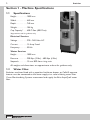
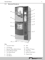
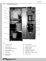
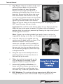
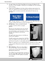

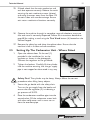
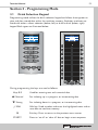
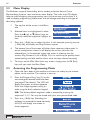
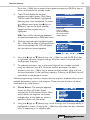
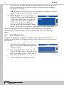
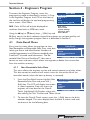

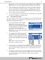
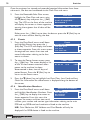

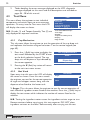
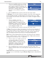
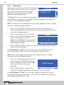

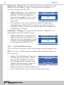
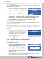
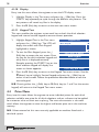

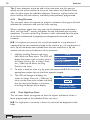

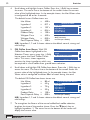
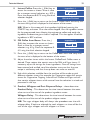
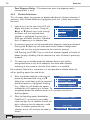
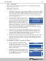
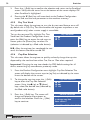

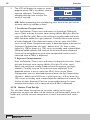

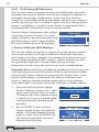
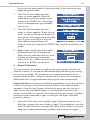
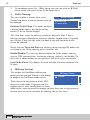
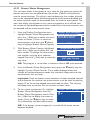

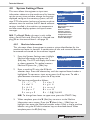

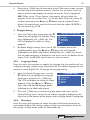
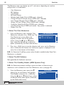
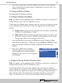


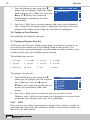


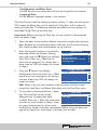


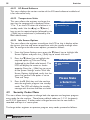
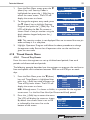
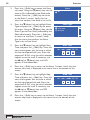
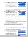
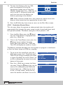
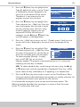
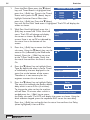
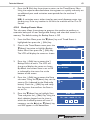

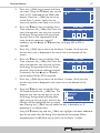

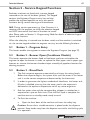
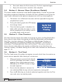


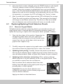


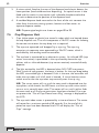
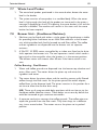
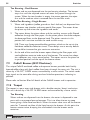

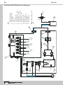

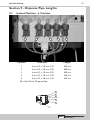

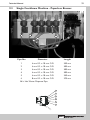
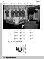
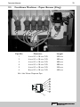
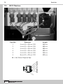


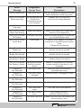

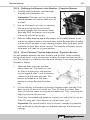

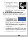
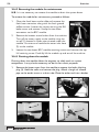
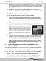


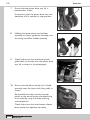
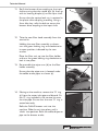
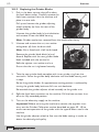
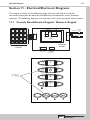
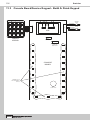

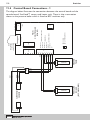

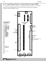

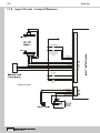
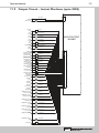
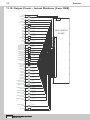
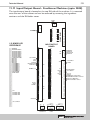
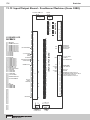
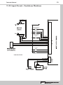
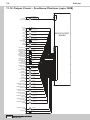

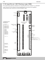
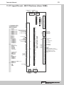

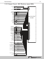

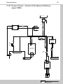
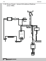


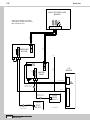
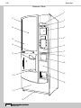

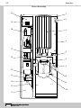
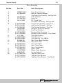
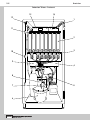
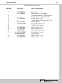


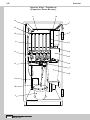
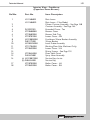
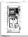

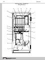

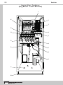
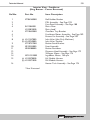
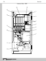

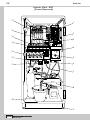
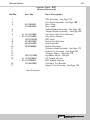

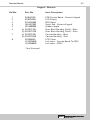
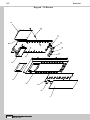
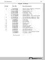
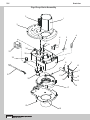
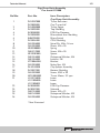
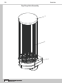
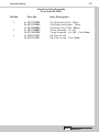
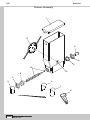
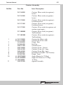


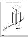
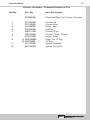
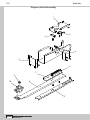
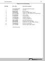

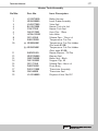


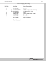
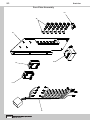
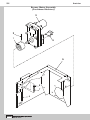

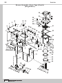
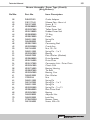
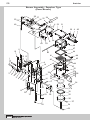
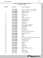
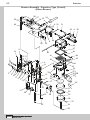
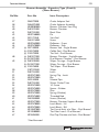

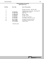
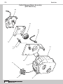
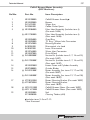
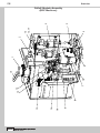
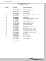
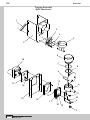
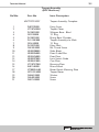

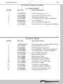

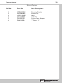
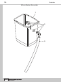
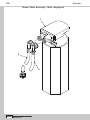
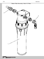
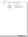
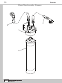
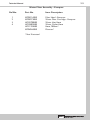


![sf-list [s]](http://vs1.manualzilla.com/store/data/005727021_1-5e70d84b679a2d9887789b982f459474-150x150.png)