1
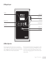
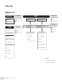
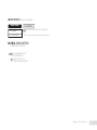
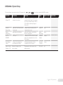
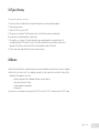
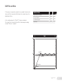
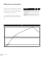
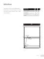
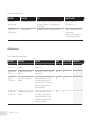
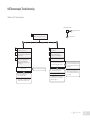
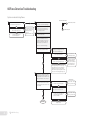
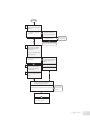
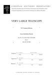
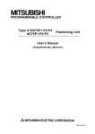
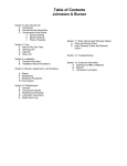
USER MANUAL REV 1.1
BURNER MANAGEMENT SYSTEM
WARNING
APPROVALS (PENDING)
THIS EQUIPMENT IS SUITABLE FOR USE IN CLASS 1, DIVISION 2,
GROUPS ABCD OR NON-HAZARDOUS LOCATIONS ONLY.
CSA 22.2 No. 199 - 2007
ANSI Z21.20 - 2007
UL1998 - 2004
WARNING: EXPLOSION HAZARD
DO NOT DISCONNECT WHILE CIRCUIT IS LIVE UNLESS AREA IS KNOWN
TO BE NON-HAZARDOUS OR EQUIVALENT
WARNING: EXPLOSION HAZARD
SUBSTITUTION OF COMPONENTS MAY IMPAIR SUITABILITY FOR
CLASS 1, DIVISION 2.
MUST CONFORM TO THE DIRECTIONS IN THIS MANUAL
THE UNIT MUST BE PROPERLY CONNECTED TO EARTH-GROUND FOR
EFFECTIVE IONIZATION OPERATION
ELECTRICAL DEVICES CONNECTED TO THE CONTROLLER MUST MEET
ELECTRICAL STANDARDS AND BE WITHIN VOLTAGE LIMITS
DO NOT SERVICE UNLESS AREA IS KNOWN TO BE NON-HAZARDOUS
DO NOT OPEN WHEN ENERGIZED
SUBSTITUTION OF COMPONENTS MAY IMPAIR THE SUITABILITY FOR
USE IN CLASS 1, DIVISION 2
REPLACEMENT FUSES MUST BE CERAMIC
FOR ANY QUESTIONS PLEASE CALL
1 855 PRO FIRE
( 776-3473 )
Class 1, Division 2, Grp
ABCD, T4A
CSA
CSA C22.2 No. 0-M91
CSA C22.2 No. 0.4-04
CSA C22.2 No. 94-91
CSA C22.2 No. 142-M1987
CSA C22.2 No. 213-M1987
CSA E60079-0:2007
CSA E60079-15:2005
UL 508, 17th Edition
ANSI-ISA-12.12.01-2007
UL 60079-0:2005
UL 60079-15:2002
GENERAL FEATURES
TEMPERATURE RATING
• Designed for the natural draft-fire, tube heater industry
-40°C to +55°C (Tested to -60°C)
-40˚F to +130°F (Tested to -76°F)
(<1MM Btuh)
• Meets or exceeds all relevant codes and standards
• Easy installation with clearly marked component I/O
• Easily accessible removable terminal connections
• Rapid 3 second shut-down on flame-out
• DC voltage spark ignition
• Low-power design to accommodate solar panel
or TEG applications
• Auto-relight or manual operation
• Transient protected and fail-safe circuits
ENCLOSURE
Polyester
309 x 234 x 134 mm (12.15” x 9.23” x 5.28”)
overall dimensions 2.3 kg (5 lb)
CSA and UL compliant for Class 1, Division 2 locations
Enclosure type 4, 4X, 12, 13
INPUTS & OUTPUTS
(4) Digital inputs for safety interlock device connections
(4) Digital outputs
(1) Flame-rod input
(2) Thermocouple inputs
See Section 1.3 for thermocouple inputs
FUSE
Only equivalent fuse should be used to replace a blown fuse.
Factory fuse: LittleFuse 0314005.HXP
(5A, 250V Ceramic, Fast Blow)
POWER REQUIREMENTS
10VDC to 28VDC (voltage must match solenoid rating) 5A MAX
CIRCUT BOARDS
All solid state
CSA compliant for Class 1, Division 2 locations
Certified for use on B.149 compliant valve trains
IGNITION BASE AND COIL
For non-hazardous mounting area only
Ignition coil mounted in the PF1800 is optionally available.
POWER COMSUMPTION
12V
24V
Controller only, display ON
2.6 W
2.8 W
Controller only, display OFF
1.1 W
1.4 W
1.1 Mounting Locations
• The control panel can be mounted on the unit skid or on a
building wall providing it does not infringe on a Class 1,
Division 1 area.
• Use control panel mounting tabs to mount in a location that
faces away from the burner housing so the operator is facing
both the enclosure and the burner housing while operating.
Other considerations may include panel access, traffic,
wire-runs and visibility.
• The control panel should be mounted about 1.5m (5’) above
ground level.
• If an external ignition coil is used, it must be mounted in a
Class 1, Division 2 enclosure or a non-hazardous location,
ideally inside the burner housing.
1.2 P&ID and Wiring Diagram
Any design used, should be approved by a qualified inspector
and approved by the gas authority having jurisdiction at the site
where the system is to be installed.
Additional P&ID and wiring diagrams are provided in a separate
application note.
1 Installation
1
1.3 Terminal Description
2
CONNECTION
DESCRIPTION
EXPECTED CONNECTIONS
RATINGS
12/24VDC
Input power 10VDC - 28VDC, 5A MAX
Input power from a DC source
10VDC - 28VDC
Internally fused at 5A
Common
Common
Ground from DC source
Internally connected
to EGND
EGND
Earth Ground
Earth or Chassis ground
Internally connected
to Common
HighTemp_TC +
(YELLOW)
Thermocouple input. High Temp
shutdown thermocouple.
HighTemp_TC (RED)
Thermocouple Input. Negative
terminal of High Temp Shutdown
thermocouple.
“TYPE K” thermocouple must be connected between
the “+” and “-” terminals and must not be electrically
connected to ground.
Process_TC +
(YELLOW)
Thermocouple input.
Process thermocouple.
Process_TC (RED)
Thermocouple Input. Negative
terminal of Process thermocouple.
Main +
Positive terminal
of the Main valve
Main -
Negative terminal
of the Main valve
Pilot +
Positive terminal
of the Pilot valve
Pilot -
Negative terminal
of the Pilot valve
1 Installation
An uninterrupted connection using “TYPE K” thermocouple
wire is required for an accurate reading.
“TYPE K” thermocouple must be connected between
the “+” and “-” terminals and must not be electrically
connected to ground.
An uninterrupted connection using “TYPE K” thermocouple
wire is required for an accurate reading.
Solenoid valves must be connected between the “+” and “-”
terminals. The negative terminal is not directly connected to ground
so a common return wire for the Main and Pilot valves cannot be
used.
Solenoid valves must be connected between the “+” and “-”
terminals. The negative terminal is not directly connected to ground
so a common return wire for the Main and Pilot valves cannot be
used.
Maximum continuous current is 2A. If
“Low Power” mode is
enabled, a peak load of
4A is permitted.
1.3 Terminal Description Continued...
CONNECTION
DESCRIPTION
EXPECTED CONNECTIONS
RATINGS
Ion +
Flame Detection Input.
Connected to a Flame-rod.
A Kanthal rod should be placed directly in the pilot flame and
connected to this input. The pilot assembly must be grounded for
the flame detection to function properly. Input is protected from
high voltage and can be connected in series with the high voltage
terminals of an external ignition coil, allowing a single flame-rod to
be used for both ignition and flame detection.
A 65VAC signal is applied to the flame rod.
The source impedance
is very high so there is
no danger of sparking.
Ion -
Ground
Ground return for flame detection. Must be connected to the
burner housing.
Coil +
Driver for the low voltage primary of
the ignition coil.
The primary of the ignition coil should be connected to this terminal. The 12/24VDC input power will be applied for 1 ms and turned
off for 50 ms while sparking.
Coil -
Ground
Ground return for the ignition coil.
Status +
The status “+” and “-” contacts will
be closed when the system is running and opened when the system
is shutdown.
Dry contact output to indicate system status to an external device.
ie. PLC.
Start +
Remote start input from an external
device. ie. PLC.
Dry contact switch is expected. The input is internally pulled up to
9VDC via a 3.75kΩ resistance. Jumper “+” and “-” if not used.
Start -
Ground
Ground return for switch. All switches can use a single
common ground return.
ESD +
External Shutdown input.
Dry contact switch is expected. The input is internally pulled up to
9VDC via a 3.75kΩ resistance. Jumper “+” and “-” if not used.
ESD -
Ground
Ground return for switch. All switches can use a single common
ground return.
Status -
This output is protected by a 250mA
thermal fuse.
250VAC/DC, 200mA,
15Ω
1 Installation
3
1.3 Terminal Description Continued...
4
CONNECTION
DESCRIPTION
EXPECTED CONNECTIONS
Pressure +
Input from a mechanical
pressure switch.
Dry contact switch is expected. The input is internally pulled up to
9VDC via a 3.75kΩ resistance. Jumper “+” and “-” if not used.
Pressure -
Ground
Ground return for switch. All switches can use a single common
ground return.
Level +
Input from a float-switch
mounted in the bath.
Dry contact switch is expected. The input is internally pulled up to
9VDC via a 3.75kΩ resistance. Jumper “+” and “-” if not used.
Level -
Ground
Ground return for switch. All switches can use a single common
ground return.
1 Installation
RATINGS
1.4 Thermocouples
ALL THERMOCOUPLES MUST BE ISOLATED FROM THE GROUND
PROCESS THERMOCOUPLE
“TYPE K”
Primary temperature control device provides high-temp shutdown. 20 AWG or larger “TYPE K” extension wire must be
used. System will shutdown if an open circuit or short circuit
is detected. Should be placed in the same thermowell as
HIGH TEMPERATURE THERMOCOUPLE.
HIGH TEMPERATURE THERMOCOUPLE
“TYPE K”
Provides high-temp shutdown. 20 AWG or larger “TYPE K”
extension wire must be used. System will shutdown if an
open circuit, short-circuit or short-to-ground is detected.
Should be placed in the same thermowell as PROCESS
THERMOCOUPLE.
* TE101 and TE102 may be different elements in the same
head of a “TYPE K” thermocouple
* For all thermocouples, avoid locating extension wire near
high-voltage lines. Shield if necessary.
1 Installation
5
2.1 Keypad Layout
DISPLAY
FLAME LIGHT
ON/OFF SWITCH
OK BUTTON
MENU BUTTON
DOWN BUTTON
UP BUTTON
RUNNING LED
STOPPED LED
2.2 Menu Operation
The system must be in manual mode in order to access the menus.
Press the “MENU” button to step through the menus. When the desired
menu is displayed, press the “OK” button to enter that menu. Once in the
menu, the “MENU” button will step through the parameters.
While viewing the desired parameter use the and buttons to adjust
the setting and “OK” to accept the change. To exit back to the “Home”
screen, press the “OK” button without making any changes. From the
“Home” screen, use the and buttons to review the current system
settings and status.
2 Control & Programming
7
2.3 Menu Map
MANUAL MODE
HOME SCREEN
System State
MENU
TO ENTER MENUS
1 -SETPOINTS
MENU
NAVIGATION
MENU
2 -SYSTEM SETUP
TO ENTER REVIEW
Process Temperature
REVIEW
MENUS
NAVIGATION
OK
OK
NAVIGATION
LEVEL 1
OK
TO RETURN HOME
TO RETURN HOME
OK
PASSWORD
OR LEVEL 2
OK
TO CYCLE
ESD Setpoint
TO CYCLE
ADJUSTMENTS
2
OK
Process Setpoint
High Temp ESD Setpoint
System Voltage Setting
Deadband
Process Setpoint
Solenoid PWM Setting
Flame
Dead Band
Display Sleep
High Temp TC Reading
Pilot Off Enable
Process Temp TC Reading
Temperature Display Units
Ambient Temp
Reset to Factory Defaults
TO ADJUST
OK
TO ACCEPT
MENU
TO CANCEL
Voltage Reading
TC Debug Screen
Alarms 1
FOOTNOTES
1 Hidden when No Alarms are present.
2 Required after password times out.
8
2 Control & Programming
AUTO MODE (MENUS NOT ACCESSIBLE)
HOME SCREEN
ADJUSTMENTS
TO ADJUST PROCESS SETPOINT IN REAL TIME*
Process Setpoint
Process Temperature
*Will also adjust Pilot Off and Low Fire Setpoints if enabled.
GLOBAL NAVIGATION
(CAN BE ENTERED AT ANY TIME)
+
CHECK FIRMWARE VERSIONS
& ENTER DEBUG MODE
OK
PRESS AND HOLD FOR 3s TO
LOCK MENUS AND RETURN HOME
2 Control & Programming
9
2.4.1 (MENU 1) Setpoints
This menu always is password protected. The password is
Cannot be accessed while BMS is running.
ON SCREEN
DESCRIPTION
FUNCTION
RANGE
DEFAULT SETTING
High Temp
ESD Setpoint: x˚C
Adjusts the High Temperature
shutdown setpoint
If process temperature reaches this
setpoint, the system will shutdown
and alarm.
0 to 1350˚C
(32 to 2462˚F)
90˚C
(149˚F)
Proc Setpoint:
x˚C (x˚F)
Main process temperature setWhen the Process temperature rises
point. Adjusts the temperature at above this setpoint, the main valve will
which the Main valve will turn off. close.
0 to 1350˚C
(32 to 2462˚F)
80˚C
(122˚F)
0 to 150˚C
(0 to 13˚F)
2˚C
(11˚F)
The Main valve will re-open when the
temperature drops below this setpoint
minus the deadband.
Dead Band:
x˚C (x˚F)
10
Adjusts the Dead Band
2 Control & Programming
The temperature buffer below the Proc
setpoint
USER SETTING
2.4.2 (MENU 2) System Setup
This menu always is password protected. The password is
Cannot be accessed while BMS is running.
ON SCREEN
DESCRIPTION
FUNCTION
RANGE
DEFAULT SETTING
System
Voltage: 12V
Configures the expected input
voltage for the system
Used by the system to determine the
over and under voltage lockout points.
At 12V the valid input range is 9.5V to
17V. At 24V the valid input range is
19V to 34V.
12V or 24V
12V
Solenoid
Power: High
Enables the Low Power mode for
the Solenoids
Indicates the power setting for the
solenoid drive circuits.
High / Low
High
Display
Sleep, Never
Sleep Mode for the Display
Allows the Display to turn off after
10 min to save power.
Never /
after 10 min
Never
Pilot Off:
ENABLED
Pilot Control
If enabled, the Pilot will turn off when
the process temperature rises to the
Proc Setpoint.
Disabled /
Enabled
Enabled
Temp Display:
Celsius
Configures the temperature
units used by the system
All display temperatures will be
converted to the chosen unit.
Fahrenheit
or Celsius
Celsius
Restore Factory
Defaults = NO
Restore all settings to the
factory default
All parameters will be reset to the
default settings.
YES or NO
NO
USER SETTING
2 Control & Programming
11
3.1 Typical Startup
The operation sequence is as follows:
1. Ensure system is installed correctly and all components are functioning properly.
2. Open manual valves.
3. Turn ON / OFF switch to “ON”
4. The purge cycle begins. The 60s purge time is started when power is applied, or the main valve is off and no flame is detected.
5. The ignition cycle begins. The pilot solenoid is opened and ignition is turned on for a 10
second trial period. If the flame is seen, the flame indicator turns on and the main valve is
opened. If the flame is not seen after this trial period, the pilot will turn off.
6. Check main valve indicator light to ensure valve is open.
3.2 Resets
• When the unit faults out, normally because an unsafe condition was detected, a reset is required.
• Before the unit can be reset, the condition causing the fault needs to be corrected. Some of the
conditions that require a reset are:
o Power supplied to the solenoids from an external source
o Gas pressure out of range
o Thermocouple wiring loose
o Flame-out
• A local reset can be done by turning the ON / OFF switch to “OFF” and then back to “ON” again.
3 Operations
13
3.3 Changing Setpoints While Running
When in Auto Mode, the Process setpoint can be adjusted in
real time using the UP & DOWN keys on the Home Screen.
To adjust any other settings, the system must be stopped in
manual mode.
3.4 Operational Description
On the PF1800 the pilot quality is monitored by a rectification
circuit. When the pilot quality gets above the minimum acceptable (50%) the STATUS contact will close to indicate that the
system is running.
TEMPERATURE CONTROL OPERATION
The PF1800 can be operated in various configurations. In all
configurations, the pilot control output and spark ignition are
used. However, control of the main valve and temperature control varies, depending on the installation and unit settings.
The PF1800 also has process high temperature monitoring. If
the process temperature increases above the High Temp ESD
setpoint, the unit will shut down by closing the main and pilot
valves and then waiting for operator intervention. The Process
High Shutdown is a dual system monitored by each microprocessor for redundant safety.
14
3 Operations
3.5.1 Pilot and Main
If the process temperature setpoint is exceeded, the main valve
closes until the temperature falls below the setpoint minus the
dead band setting.
In this configuration, the “Pilot Off” feature is disabled.
This setup fires the main fully until the thermocouple reading
exceeds “Process” setpoint.
EXAMPLE SETTINGS
˚C
˚F
High Temp ESD Setpoint
100
212
Process Setpoint
50
122
Low Alarm Setpoint
10
50
Dead Band
4
7
˚C
TIME
˚F
212
100
MAIN OFF
50
122
DEAD BAND
MAIN ON
CLEAR ALARM
0
MAIN ON
32
3 Operations
15
3.5.2 High Temperature Emergency Shutdown
This particular graph is a representation of the a “High Temperature Shutdown.” As shown, the ‘Pilot Off’ feature is enabled.
This means that there is no heat being applied to the firetube,
yet the temperature continues to increase.
Once the High Temp ESD setpoint has been reached, the system will shut down and require user input to acknowledge the
error.
˚C
˚C
˚F
High Temp ESD Setpoint
100
212
Process Setpoint
50
122
Low Alarm Setpoint
10
50
Dead Band
4
7
TIME
100
50
EXAMPLE SETTINGS
˚F
ESD
MAIN & PILOT OFF
DEAD BAND
212
122
CLEAR ALARM
MAIN ON
0
16
32
3 Operations
3.5.3 Pilot Off Control
The operation is the same as the Pilot and Main control but
the pilot will also turn off when the main does. The unit will not
re-light until the temperature is below the “Process” setpoint
minus the dead band.
EXAMPLE SETTINGS
˚C
˚F
High Temp ESD Setpoint
100
212
Process Setpoint
50
122
Low Alarm Setpoint
10
50
Dead Band
4
7
˚C
TIME
˚F
212
100
PILOT & MAIN OFF
50
122
DEAD BAND
PILOT & MAIN ON
CLEAR ALARM
0
MAIN ON
32
3 Operations
17
4.1 Normal Operation
SYSTEM STATUS
RESPONSE
System off and there is a flame
The system is in Power Save mode. Press any button to wake.
System off and there is no flame
The system is in Power Save mode. Press any button to wake. If still no response, check power.
Ready
Unit is in manual mode
• Turn switch to ON position
4.2 Error Messages
When there is more than one alarm, the abbreviated on-screen display will be shown. When a shutdown occurs, the system
will enter a “lock-out” state with all outputs off. Selecting the “OK” button, toggling the “Start” contacts, or a power cycle,
will be required to clear any of the following errors once the problem has been corrected.
18
ON SCREEN
DESCRIPTION
CAUSE
CORRECTIVE ACTION
Proc Thermocouple
Error
Or Proc TC
Thermocouple error
Process thermocouple is open or value is out of range
• Check thermocouple wiring
• Replace thermocouple
HH Thermocouple
Error
Or ProH TC
Thermocouple error
High Temp thermocouple is open or value is out of range • Check thermocouple wiring
• Replace thermocouple
ESD Input
Or
ESD Inp
Emergency Shut Down
ESD input open
• Check contact
Flame Fail
Or
Flame
Flame Fail
Pilot not detected, retry limit expired
• Check fuel, air & ignition
• Return to auto mode and try again
• Check flame detection during
ignition trial
4 Troubleshooting
4.2 Error Messages Continued...
ON SCREEN
DESCRIPTION
CAUSE
CORRECTIVE ACTION
Start Input Open
Or
STRT INP
Remote Start input is open
Start contacts open
• Close START contacts
• Check wiring
Pressure
Or
IVP
Low Pressure Switch open
Low Pressure switch input open
• Check pressure switch wiring
• Check fuel pressure
• Check wiring
Level Input
Or
Lvl Inp
Level switch open
Level switch has opened
• Check level switch wiring
• Check bath level
• Check wiring
High Temp
Or
Hi Temp
High Temperature Shutdown
Process or High Temp thermocouple has reached the
High Temp ESD setpoint
• Verify setpoints
• Allow bath to cool
• Calibrate Process and High Temp
High Voltage
Or
Hi Volt
High Voltage
Voltage input to the board is too high
• Reduce the input voltage
• If the system is running off of
2V, ensure that the system
setting is correct in menu 4
Low Voltage
Or
Lo Volt
Low Voltage
Voltage input to the board is too low
• Increase the input voltage
• If the system is running off of
24V, ensure that the system
setting is correct in menu 4
Flame Detected
Before Start
Flame detected before start
Flame detected when trying to ignite the burner
• Ensure valves are closed
• If the distance from the pilot
valve to the nozzle is long then
try increasing the purge time
• Check for other sources of flame
Solenoid Feedback
Error
Solenoid power error
A solenoid output is detected as being on when it
should be off, or off when it should be on
• Check for shorted outputs
• Check solenoid wiring
Master Power not
Detected
Master power error
Master power switch is not turning on, or is on when it
should be off
• Check for shorted outputs
4 Troubleshooting
19
4.2 Error Messages Continued...
20
ON SCREEN
DESCRIPTION
CAUSE
CORRECTIVE ACTION
Error xx
Or
Sys Err
Internal system error
Internal error detected in the system
• Reset both boards or cycle power
• Replace terminal card
EEPROM Error
Internal system error
The Door Card micro cannot communicate with the
EEPROM or there was a CRC error in the EEPROM
• Reset the Door Card or cycle power
• Replace the door card
Flame Test
Internal System Error
Fault in the flame detection circuit.
• Move the flame rod further into
the flame
• Check the grounding from the
pilot nozzle to the PF2100
• Replace the ribbon cable
• Replace terminal card
TCs Not Equal
Thermocouple error
The High Temp Thermocouple reading on the door and
terminal cards is not the same, or “High Temp” and
“Process” readings are greater than 10˚C (50˚F) apart.
The three temperatures will be shown.
DC High Temp, TC High Temp, Proc Temp
• Reset both, or cycle power
• Check the thermocouple wiring
• Verify that the “Process” and
“High Temp” thermocouples are
reading the same temperature
Ambient Temps Not
Equal
Internal System Error
The ambient (cold injunction) temperature as read on
the door card and terminal card are more than 10˚C
(50˚F) apart
• Verify the thermocouple wiring
• Calibrate the thermocouples
Control Error
Internal System Error
Error in the control system
• Reset or cycle power
• Replace the door card
Key Stuck Error
“Key name”
Keypad problem
Key shorted at startup
• Reset or cycle power
• Inspect ribbon cable connection
• Replace the keypad
OFF
Switch Off
Switch Off
• Turn switch On
Comparison “error”
Internal System Error
4 Troubleshooting
• Reset or cycle power
• Reverse ribbon
• Replace the ribbon cable
• Replace terminal
4.2 Error Messages Continued...
ON SCREEN
DESCRIPTION
CAUSE
CORRECTIVE ACTION
Terminal Card
Communications
Communication error
Communication error between the door card and terminal card
• Reset or cycle power
• Check ribbon cable connection
• Reverse ribbon
• Replace ribbon
• Replace the terminal card
Terminal Card
Command Refused
Internal system error
The terminal card has rejected a command sent by the
door card
• Check the solenoid wiring, if
there are crossed wires or if
a common wire is used for
the negative return this error
can result.
• Reset or cycle power
• Reverse ribbon
• Replace the ribbon cable
• Replace one or both cards
Terminal Card
Output Feeback
Solenoid power error
A solenoid output is detected as being on when it
should be off, or off when it should be on
• Reset or cycle power
• Check for shorted outputs
Terminal Card
Reciprocal Comp
Internal system error
The reciprocal comparison between the cards does not
agree
• Reset or cycle power
• Reverse ribbon
• Replace the ribbon cable
• Replace one or both cards
Terminal Card
Shutdown Detect
External system error
Contact input detected open by the terminal card:
ESD, High Pressure, Low Pressure, Level
• Reset or cycle power
• Check wiring
• Reverse ribbon
• Replace the ribbon cable
Terminal Card
Invalid Command
Internal system error
The terminal card has received an invalid command
from the door card.
• Reset or cycle power
• Reverse ribbon
• Replace the ribbon cable
• Replace the door card
4 Troubleshooting
21
4.2 Error Messages Continued...
ON SCREEN
DESCRIPTION
CAUSE
CORRECTIVE ACTION
Terminal Card
High Temp Alarm
High Temperature Shutdown
Process or High Temp Thermocouple has reached the
High Temp ESD setpoint. This is detected by the
terminal card first.
• Reset or cycle power
• Allow bath to cool
Terminal Card
HH TC Grounded
Thermocouple error
High Temp Thermocouple is shorted to ground.
• Check for wiring faults with the
thermocouples
• Check for a short to ground on
the high temp thermocouple.
4.3 Calibration
Factory calibration has been performed.
22
ON SCREEN
DESCRIPTION
FUNCTION
RANGE
DEFAULT SETTING
Cal: Proc TC
Zero = No
Process thermocouple zero
calibration
Short the Proc “+” and “-” contacts
and select Yes
N/A
N/A
Cal: High Temp TC
Zero = No
High Temp thermocouple zero
calibration
Short the ProH “+” and “-” contacts
and select Yes
N/A
N/A
Cal: Proc
TC Span = xxC
Process thermocouple span
calibration
Provide a calibrated 212˚F signal
(from thermocouple in a block or
meter) to the Process TC input and
adjust the reading to match the
applied temperature.
N/A
N/A
Cal: High Temp
TC Span = xxC
High Temperature thermocouple
calibration
Provide a calibrated 212˚F signal
(from thermocouple in a block or
meter) to the High Temp TC input
and adjust the reading to match
the applied temperature.
N/A
N/A
4 Troubleshooting
USER SETTING
4.4 Thermocouple Troubleshooting
Problem with Thermocouples.
QUESTION ARE IN WHITE RECTANGLES
?
1
Ensure that both the High Temp and
Process thermocouples are connected.
YES
A
2
3
4
2
3
Check the thermocouple wiring, ensure
that the thermocouples are paired correctly
and not reversed.
4
The thermocouple indicated by the system
may be faulty. Install a jumper across
HighTemp_TC+ and HighTemp_TC-.
Also install a jumper across Process_TC+
and Process_TC-.
YES
There is likely a problem with the
thermocouple or the wiring
Verify that there is continuity between the
red and yellow for each thermocouple
NO, ALWAYS MOVES TO THE RIGHT
YES, ALWAYS MOVES DOWN
B
System reading Process TC, ProcTC,
HH Thermocouple or ProcH TC
Did the error clear?
NO
System reading TC’s not equal or
TC Mismatch
Set a Multi-Meter to read mili-volts DC
(mVDC) and measure across
HighTemp_TC+ and HighTemp_TCAlso measure across Process_TC-
Are the voltages measured across the
two thermocouples within 0.1mVDC?
NO
One of the circuit boards may be faulty
NO
The system is likely reading correctly. Set
the meter to read continuity and check that
the thermocouples are paired correctly and
not reversed.
YES
The system is likely out of calibration
Re calibrate the HighTemp_TC and Process_TC
If the thermocouples are paired correctly
and not reversed it is possible that one of
the thermocouples is faulty and will need
to be replaced
If the calibration did not resolve the problem
it is possible that one of the circuit boards
will need to be replaced
4 Troubleshooting
23
4.5 Flame Detection Troubleshooting
System is not detecting flame.
1
Does the flame quality drop from 100%
(Pilot) when the main comes on?
YES
Does the system stay running
with the flame arrestor open?
YES
Clean the arrestor and look
for other air restrictions
2
NO
NO
The draft from the main
could be pulling the pilot
flame away from the
flame rod.
Reposition the flame rod.
3
4
QUESTION ARE IN WHITE RECTANGLES
Ensure that the pilot orifice is correct
for the gas used. (#54 for natural gas)
?
Ensure that there is a metal-on-metal
connection from the pilot nozzle to
the housing and a ground wire from
the housing to the 2100
YES
NO
NO, ALWAYS MOVES TO THE RIGHT
YES, ALWAYS MOVES DOWN
Ensure that the ignition rod is fully
immersed in the flame
With the system powered and in idle
mode, set a Multi-Meter to read AC
voltage and measure across the ION +
and ION - terminals. The voltage will
fluctuate a bit due to the flame test.
Take note of the maximum voltage
Is the voltage greater than 25VAC?
NO
Remove the wire from ION + and
measure the AC voltage between the
ION + and ION - terminals again.
Is the voltage above 35VAC?
NO
YES
Is the wire run length from the
burner to the PF2100 longer than 25’
YES
NO
YES
The length loading on the wire is too high.
Using ignition wire for ION + will allow the
signal to be run up to 50’. Using separate
rods for flame detection and ignition can also
reduce the ION + load by bypassing the coil.
5
It is possible that the
terminal card is faulty
Something is loading the
signal. Ensure that the
wire type is not shielded.
Look for partial ground
shorts or nicked wires.
Measure the AC volatage from the flame
rod to ground if the rod is accessible. If it
is not accesible remove the wire from the
flame rod and measure on the connector.
THERE ARE TWO RODS
Is the voltage measured at the rod close to
the voltage measured across the ION + and
ION - terminals?
NO
Is the same rod being used for
both flame detection and ignition?
NO
Check the ION + wire for
shorts to ground or nicks.
NO
Check the ION + wire for
shorts to ground or nicks.
YES
Measure the AC voltage on the ION +
wire where it connects to the coil.
YES
NEXT PAGE
24
4 Troubleshooting
Is it close to the same voltage that
was measured across the ION +
and ION - terminals?
YES
Replace the coil.
PREVIOUS PAGE
6
Set the Multi-Meter to measure DC voltage
across ION + and ION - with the system in
manual mode.
Is the reading across ION + and ION around +5VDC?
NO
Remove the wire from ION + and
measure the DC voltage between
the ION + and ION - terminals again.
Is the voltage across the ION + and
ION - terminals around +5VDC?
It is possible that the
terminal card is faulty
YES
YES
7
NO
Check the ION + wire for nicks or other faults.
Put the system into Auto Mode and
monitor the voltage on the Multi-Meter.
While sparking the voltage will jump
around, ignore this.
Take note of the voltage after the sparking
while the flame is present.
Did the voltage drop below +5V when the
flame was present?
8
9
NO
YES
The system is not seeing the flame at all.
The circuit from the rod through the flame
to the nozzle to ground is not being
completed.
Check the grounding to the pilot nozzle.
The system is sensing flame, just not
enough.The DC voltage should drop to
-5VDC or lower (-8VDC is better) for
stable flame detection.
Check for cracked ceramic on the flame rod.
Adjust the flame rod positioning to try
to decrease the voltage while the flame
is present.
The problem could be related to flame anchoring.
To verify this place a grounded rod in the flame.
Did placing the grounded rod in the flame improve the DC voltage reading?
NO
Recheck the orifice size
and increase the pilot
pressure
YES
Try replacing the pilot nozzle
YES
Set the system up to use separate rods
for flame detection and ignition
4 Troubleshooting
25
WWW.PROFIREENERGY.COM
© 2011 PROFIRE