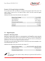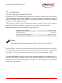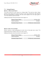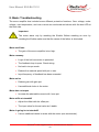
1
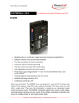
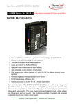
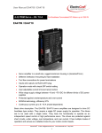
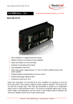
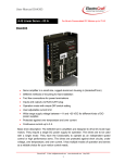
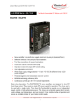
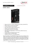
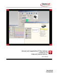
User Manual SCA-B4-70-10
4–Q PWM Servo – 10 A
For Brushless-Commutated DC Motors up to 700 W
SCA-B4-70-10
• Servo amplifier in a rugged aluminium housing
• Different methods of mounting for fast installation
• Inputs and outputs via screw terminals
• Operation mode setting with jumpers
• User adjustable current limit
• Wide range supply voltage between +11 and +70 VDC for different kinds of DCpower supplies
• Protected against overtemperature and over-current
• MOSFet-technology, efficiency 95%
• Continuous current up to 10 A
Basic drive description: The SCA-B4-70-10 servo amplifiers are designed to drive DC
brushless type motors. They require a single DC power supply for operation. The drives
are to be used with a single motor. They have the functionality to operate as an
independent speed control or high performance servo. The drives are protected against
short circuits, under voltage, over temperature, and over current. It has multiple modes of
operation and serves as a reliable choice for your motion control needs.
ElectroCraft®
E-Mail: [email protected]
1
www.electrocraft.com
May 2009
User Manual SCA-B4-70-10
Table of Contents
1.
Safety & Installation ......................................................................... 3
2.
Specifications: .................................................................................. 4
3.
Drive Overview .................................................................................. 7
4.
Wiring............................................................................................... 10
5.
Explanation of Terminals, Potentiometers & Jumpers ............... 19
6.
Glossary .......................................................................................... 23
7.
Description of Inputs and Outputs ................................................ 29
8.
Basic Troubleshooting ................................................................... 33
9.
Accessories & Options .................................................................. 34
10. Warranties & Disclaimers .............................................................. 35
11. Dimensions ..................................................................................... 36
12. Mounting Din rail adapter .............................................................. 37
Used Symbols
Indicates a warning or caution concerning operations that may lead to
death or injury to persons, or damage to property if not performed correctly.
In order to use the drive safely, always pay attention to these warnings.
Indicates a clarification of an operation, or contains additional explanations,
or operational requirements for a procedure. Reading these notes is much
recommended.
ElectroCraft®
E-Mail: [email protected]
2
www.electrocraft.com
May 2009
User Manual SCA-B4-70-10
1. Safety & Installation
The SCA-B4-70-10 requires installation by qualified personal which must pay
attention to significant safety and other regulatory standards. They should be
thoroughly familiar with the entire system before beginning installation.
Before final operation of machine be sure to test hookup with motor
disconnected from the load. Improper wiring could cause a “motor run away”
condition, and cause serious injury or damage to the machine and personal.
Before starting installation of the SCA-B4-70-10, be sure that main power is
disconnected. After powering the drive it should not be touched by hand or
risk shock.
Take care that in case of regeneration or in brake operation the energy
recovery must be buffered by the power supply and / or a braking module.
Ensure with electronically stabilized power supplies that protection circuit isn’t
react.
Don’t switch off the power supply while the motor is turning, in this case the
drive could be destroyed by regeneration.
We recommend connecting a capacitor of 1000 µF per each ampere output
current close to power input, in parallel.
Do not repair or open drives enclosure. Result would result in personal injury
and would void all warranties.
The SCA-B4-70-10 complies with the European directive EN61800-3 (1996).
The followings points must followed:
•
A metal mounting plate with correct grounding is mandatory.
•
For installation purposes, tooth lock washers have to be used.
•
For most wiring schemes, only shielded cables are admissible, to
suppress interference with other devices. Damaged items have to be
replaced.
•
Provide for a large contact area between shields and mounting plate.
•
The motor has to be grounded.
•
The drive is an Electrostatic Sensitive Device (ESD). Electrostatic
discharge needs to be avoided
NOTE:
Certain applications may involve special requirements. Consult Factory!
ElectroCraft®
E-Mail: [email protected]
3
www.electrocraft.com
May 2009
User Manual SCA-B4-70-10
2. Specifications:
2.1
Electrical Data
Power Supply Voltage
+11 to +70 VDC
(Residual ripple <5 %)
(The lower limit is monitored
integrated undervoltage trip)
by
WARNING: Do not exceed 70V.
Overvoltage will damage the drive.
Nominal Current
10 A
Peak Current
20 A
Maximum Power (only achievable with
additional heatsink & proper mounting,
see accessories.)
700 W
Switching Frequency
49 kHz
Efficiency
95 %
Induction Specification & caution for low Optional choke modules are often an
inductance motors
economical solution for low inductance or
other motors, if an overheating situation
occurs in regular intervals. Contact
factory service for details.
Power terminals
The diameter must be suited for the
current load. The recommendation for
the drive is 1,5 mm2 (AWG16). Maximum
wire diameter with respect to the terminal
is 2,5 mm2 (AWG14) or 1,5 mm2
(AWG16) for stranded wires. Strip the
wire insulation of the cables on a length
of maximal 8 mm. For stranded wire, use
end sleeves with the corresponding
length.
Signal terminals
The
recommendation
is
0,5 mm2
(AWG21), the min. is 0,14 mm2 (AWG26)
and the max. is 1,5 mm2 (AWG16). Strip
the wire insulation of the cables on a
length of maximal 7 mm. For stranded
wire, use end sleeves with the
corresponding length.
ElectroCraft®
E-Mail: [email protected]
4
www.electrocraft.com
May 2009
User Manual SCA-B4-70-10
2.2
Mechanical Data
Mechanical Dimensions L x W x H
180 x 100 x 40 mm
Weight
580 g
Mounting
2.3
2.4
M4 screws or Din Rail Mounting
Ambient Conditions
Operation Temperature
-10 to +45 oC
Storage Temperature
-40 to +85 oC
Humidity (Non Condensing)
20 % to 80 % RH
Overtemperature Protection
+80 °C
Digital and Analog Inputs
Enable
8…+30 VDC; Resistance = 4,7 kOhm
Hall A, B, C
TTL, +5 VDC; Resistance = 1 kOhm
Encoder A, B
TTL, +5 VDC; Resistance = 1 kOhm;
max. 100 kHz
Analog -10 – +10 VDC ;
Resistance = 20 kOhm
-Set value -- +Set value
2.5
Outputs
Auxiliary Voltage Outputs +5V
+5 V / 100 mA
Auxiliary Voltage Output +15V
+15 V / 20 mA
Auxiliary Voltage Output -15V
-15 V / 20 mA
Ready/Error
Open Collector / +30 VDC; max. 20 mA
Monitor I
Analog 0 – +10 VDC with = 0,5 V / A
Resistance = 10 kOhm
Monitor n
Analog 0 – +10 VDC ;
Resistance = 10 kOhm
ElectroCraft®
E-Mail: [email protected]
5
www.electrocraft.com
May 2009
User Manual SCA-B4-70-10
2.6
Control LEDs
OK
LED green
The LED is lit when the drive is ready to
work.
Fault
LED red
The lamp is lit if the overtemperature, the
undervoltage, the overvoltage or the
overcurrent protection circuit have been
initiated.
ElectroCraft®
E-Mail: [email protected]
6
www.electrocraft.com
May 2009
User Manual SCA-B4-70-10
3.
Drive Overview
3.1
Block Diagram
ElectroCraft®
E-Mail: [email protected]
7
www.electrocraft.com
May 2009
User Manual SCA-B4-70-10
3.2
Input & Output Schematics
ElectroCraft®
E-Mail: [email protected]
8
www.electrocraft.com
May 2009
User Manual SCA-B4-70-10
3.3
Control Elements
3.4
Operation Modes
Hall Mode
At hall mode the feedback information is coming from hall switches which are mounted in
the motor or a hall encoder which is mounted at the motor. The speed regulation is good at
each load condition and qualified for each application to control the speed of a system also
for high speed application.
Encoder Mode
At encoder mode feedback information is coming from the encoder signals. The encoder is
mounted at the motor. The speed regulation has got a high performance at each load
condition and qualified for each application to control exactly the speed of a system
especially for low speed application. The maximum achievable speed in this mode is limited
through the encoder input frequency.
Torque Mode
At torque mode the drive does only control the current of the motor. This control loop is very
fast but the speed is moving with the load due to the constant current. This mode is used in
application with force control or as a fast power amplifier for positioning systems.
ElectroCraft®
E-Mail: [email protected]
9
www.electrocraft.com
May 2009
User Manual SCA-B4-70-10
4. Wiring
According to the safety directives, a correct cable selection is mandatory. Regular
inspection is advisable. Damaged, burned or kinked items have immediately to be
exchanged.
Power (⊕Vcc - Power GND)
•
Normally no shielding required.
•
When connecting several amplifiers to the same supply pack, use star point
wiring.
Motor Wiring (> 30 cm)
•
Only shielded cables are recommended.
•
Connect the shield to the ground lug of the servo amplifier.
•
A separate cable has to be used.
•
Choke modules are useful to reduce PWM-pulses.
Connection to hall and encoder (> 30 cm)
•
Only shielded cables are recommended.
•
Connect the shield to the controller.
•
A separate cable has to be used.
Analog Signals (I max, +Set value, -Set value, Monitor I, Monitor n)
•
In most cases no shielding required. This may be different for low level signals or
in an environment with strong magnetic interference.
•
Connect the shield on either end of the cable. For 50/60 Hz interference, remove
the shield on one side.
Digital Signals (Enable, Ready/Error)
•
No shielding required.
To verify a trouble-free operation and the conformity to CE regulation, it makes only sense
to test the system as a whole, with all components installed (motor, amplifier, supply pack,
EMC filters cables etc.).
Note: To improve the noise immunity, always connect unused logical inputs to a fix
potential.
ElectroCraft®
E-Mail: [email protected]
10
www.electrocraft.com
May 2009
User Manual SCA-B4-70-10
4.1 Wiring Example I – Hall Mode
ElectroCraft®
E-Mail: [email protected]
11
www.electrocraft.com
May 2009
User Manual SCA-B4-70-10
4.1.1 Setting of the Jumpers
Phasing
60°
120°
Timing
1
Select max. RPM
2
1/1
1/2
1/4
Set Value via
1/8
Offset- Connecpot
tor
Note: Advanced information’s about the jumpers refer chapter 5.3.
4.1.2 Adjustment procedure for Hall mode
1. Potentiometer pre setting refer chapter 5.2.
2. After setting of the jumpers set the Enable input to HI. Choose the maximum set
value (e.g. 10 V). Turn the potentiometer n max, until the desired maximum speed is
reached.
3. Adjust the current limiter to a value requested by you with the I max potentiometer. It
is of major importance that this value is lower than the maximum admissible constant
current (see motor data sheet). To measure the motor current use the Monitor I
output, or a current probe in one of the motor cables with a oscilloscope or a
multimeter.
4. Set the Gain fine potentiometer to the middle, than slowly raise the value of the Gain
coarse potentiometer. If the motor begins to work unsteadily, to vibrate or to cause
excessive noise, carefully lower the gain factor again, until the instability symptoms
have disappeared for all load selections. Fine adjusting is possible with Gain fine
potentiometer.
5. Set the set value to zero and adjust the Offset potentiometer until motor is standing
still.
ElectroCraft®
E-Mail: [email protected]
12
www.electrocraft.com
May 2009
User Manual SCA-B4-70-10
4.2 Wiring Example II – Encoder Mode
ElectroCraft®
E-Mail: [email protected]
13
www.electrocraft.com
May 2009
User Manual SCA-B4-70-10
4.2.1 Setting of the Jumpers
Phasing
60°
120°
Timing
1
Select max. RPM
2
1/1
1/2
1/4
Set Value via
1/8
Offset- Connecpot
tor
Note: Advanced information’s about the jumpers refer chapter 5.3.
4.2.2 Adjustment procedure for Encoder mode
1. Potentiometer pre setting refer chapter 5.2.
2. After setting of the jumpers set the Enable input to HI. Choose the maximum set
value (e.g. 10 V). Turn the potentiometer n max, until the desired maximum speed is
reached.
3. Adjust the current limiter to a value requested by you with the I max potentiometer. It
is of major importance that this value is lower than the maximum admissible constant
current (see motor data sheet). To measure the motor current use the Monitor I
output, or a current probe in one of the motor cables with a oscilloscope or a
multimeter.
4. Set the Gain fine potentiometer to the middle, than slowly raise the value of the Gain
coarse potentiometer. If the motor begins to work unsteadily, to vibrate or to cause
excessive noise, carefully lower the gain factor again, until the instability symptoms
have disappeared for all load selections. Fine adjusting is possible with Gain fine
potentiometer.
5. Set the set value to zero and adjust the Offset potentiometer until motor is standing
still.
ElectroCraft®
E-Mail: [email protected]
14
www.electrocraft.com
May 2009
User Manual SCA-B4-70-10
4.3 Wiring Example III – Torque Mode
ElectroCraft®
E-Mail: [email protected]
15
www.electrocraft.com
May 2009
User Manual SCA-B4-70-10
4.3.1 Setting of the Jumpers
Phasing
60°
120°
Timing
1
Set Value via
2
Offset- Connecpot
tor
Note: Advanced information’s about the jumpers refer chapter 5.3.
4.3.2 Adjustment procedure for Torque mode
1. Potentiometer pre setting refer chapter 5.2.
2. After setting of the jumpers set the Enable input to HI. Choose the maximum set
value (e.g. 10 V). Adjust the current limiter to a value requested by you with the I max
potentiometer. It is of major importance that this value is lower than the maximum
admissible constant current (see motor data sheet). To measure the motor current
use the Monitor I output, or a current probe in one of the motor cables with a
oscilloscope or a multimeter.
3. Set the set value to zero and adjust the Offset potentiometer, to the standstill of the
motor.
ElectroCraft®
E-Mail: [email protected]
16
www.electrocraft.com
May 2009
User Manual SCA-B4-70-10
4.4 Wiring Example IV – Minimal Mode
ElectroCraft®
E-Mail: [email protected]
17
www.electrocraft.com
May 2009
User Manual SCA-B4-70-10
4.5
Wiring Example V
ElectroCraft®
E-Mail: [email protected]
18
www.electrocraft.com
May 2009
User Manual SCA-B4-70-10
5. Explanation of Terminals, Potentiometers & Jumpers
5.1 Terminals
Terminal
Label
Description
Pin 1 & 2 connect to power supply.
XA
Pin 3 & 4 &5 connect to motor.
Pin 6 voltage output +5 VDC.
Pin 7 & 8 input encoder feedback.
XB
Pin 9 signal GND.
Pin 10 & 11 & 12 input for hall signals.
Pin 13 input Enable.
Pin 14 voltage output +15 VDC.
Pin 15 signal GND.
Pin 16 voltage output -15 VDC.
XC
Pin 17 & 18 input set value.
Pin 19 voltage output for current.
Pin 20 voltage output speed monitor.
Pin 21 output signal Ready/Error.
ElectroCraft®
E-Mail: [email protected]
19
www.electrocraft.com
May 2009
User Manual SCA-B4-70-10
5.2 Potentiometers
Potentiometer
Function
Turning to the Left
(ccw)
Turning to the Right
(cw)
Gain coarse
Gain
Factor lowered
Factor raised
Gain fine
Gain
Factor lowered
Factor raised
n max
Definition of max. number
of revolutions
Value is decreased
Value is increased
I max
Set value for max. current
Upper limit lowered
Upper limit raised
Offset
Zero Offset (motor stands
still)
Motor rotates
counterclockwise
Clockwise rotation
Potentiometer setting for start up:
Gain coarse
Gain fine
n max
I max
Offset
Left stop
Middle
Middle
Middle
Middle
ElectroCraft®
E-Mail: [email protected]
20
www.electrocraft.com
May 2009
User Manual SCA-B4-70-10
5.3 Jumpers
J1
Phasing
Setting of the Hall arrangement
Open
Phase 120°
The halls in the motor have an arrangement of 120°.
Set
Phase 60°
The halls in the motor have an arrangement of 60°.
Setting of the hall sensor timing
J2
Timing
Sets the timing to one of the two possible options.
Open
Timing 2
This setting has to be used if it isn’t possible to control the motor.
Set
Timing 1
Changes direction of rotation for the electrical field in motor to the
opposite of Timing 1.
J3
Set value.
Methods of entering the set value
Open
Set val. extern
External selection using a voltage between XC/16 and XC/17.
Set
Set val. intern
The internal Offset potentiometer is used.
ElectroCraft®
E-Mail: [email protected]
21
www.electrocraft.com
May 2009
User Manual SCA-B4-70-10
J4
J5
J6
J7
J8
J9
Function Mode
Open
Open
Open
Set
Set
Set
Speed Control by Hall
Open
Set
Set
Set
Open
Open
Speed Control by Encoder
Set
Open
Open
Open
Open
Open
Torque Control
J10
J11
Select max. RPM
Open
Open
Maximum speed range of e.g. 40000 rpm at a 2-pol motor.
Open
Set
Maximum speed is set to 1/2.
Set
Open
Maximum speed is set to 1/4.
Set
Set
Maximum speed is set to 1/8.
ElectroCraft®
E-Mail: [email protected]
22
www.electrocraft.com
May 2009
User Manual SCA-B4-70-10
6. Glossary
Gain coarse; Gain fine
The dynamical behaviour of the servo amplifier must be compatible to the particular
connected motor. The adjusting procedure is performed using the Gain potentiometers. A
bad adaptation (i.e. if the Gain value has been selected too high) can be easily recognized
by excessive motor vibration or noise. Consequential mechanical damages cannot be
excluded; furthermore an overtemperature situation may arise, due to high currents inside
the motor.
When setting the gain value during a stop, the result most probably will have to be
accommodated one more time, because the dynamical reaction of the motor at a higher
speed will not be sufficient.
Always remember that these potentiometers do not only act on the gain itself, but also on
the frequency of the entire control loop.
n max
Use this potentiometer to adapt the desired maximum speed to the amplitude of the present
set value. For Example: if maximum of 5V is to be used for maximum Speed then send 5V
and adjust that maximum with the n max potentiometer.
Take care not to exceed meaningful limits. An exaggerated value may entail problems for
the control of the servo amplifier, making it impossible e.g. to line-up the system in speed
control operation under load.
I max
The following action requires the motor to be operated with maximum load. The motor
current may be measured e.g. using current probe with effective value display, or by means
of an ammeter located in the motor line.
I max decide the maximum possible motor current.
The following limits have to be observed:
-
Left stop: 5 % of rated current of 10A
-
Right stop: 100 % of rated current + (0 – +10 %)
Note:
Do not overheat the motor. For this reason, the I max limit should always be
selected lower than the maximum admissible constant current.
ElectroCraft®
E-Mail: [email protected]
23
www.electrocraft.com
May 2009
User Manual SCA-B4-70-10
Offset
There are two distinct functions for the Offset-Potentiometer:
1. Levelling the position at which the motor stands still.
2. Selection of the Set Value. This task requires the jumper J3 (Set value.) is set.
In any mode, this feature is available and offers the possibility of a quick
functional test.
It is advisable to begin the subsequent levelling procedure with an idle run of the motor.
However you cannot expect this calibration to be stable in the long term, because the motor
as well as the controller are always subject to thermal influences.
Hall mode
This is a closed loop speed mode which is using the hall signals as a feedback input for the
speed.
Encoder mode
This is a closed loop speed mode that receives the speed information from the encoder.
The advantage of a better speed regulation is given especially at lower speed.
Torque mode
In this mode the driver controls only the current into the motor. The speed of the motor
depends on the load because only the output force of the motor is regulated.
Brushless motor
A Class of motors that operate using electronic commutation of phase currents, rather than
electromechanical (brush-type) commutation. Brushless motors typically have a permanent
magnet rotor and a wound stator.
Commutation
Is a term which refers to the action of steering currents or voltages to the proper motor
phases so as to produce optimum motor torque. In brush type motors, commutation is done
electromechanically via the brushes and commutator. In brushless motors, commutation is
done by the switching electronics using rotor position information obtained by Hall sensors.
ElectroCraft®
E-Mail: [email protected]
24
www.electrocraft.com
May 2009
User Manual SCA-B4-70-10
Hall sensor
Is a feedback device which is used in a brushless servo system to provide information for
the amplifier to electronically commutate the motor. The device uses a magnetized wheel
and hall effect sensors to generate the commutation signals.
Encoder
Is a feedback device which converts mechanical motion into electronic signals. The most
commonly used, rotary encoders, output digital pulses corresponding to incremental angular
motion. For example, a 1000-line encoder produces 1000 pulses every mechanical
revolution. The encoder consists of a glass or metal wheel with alternating transparent and
opaque stripes, detected by optical sensors to produce the digital outputs.
Back EMF
The voltage generated when a permanent magnet motor is rotated. This voltage is
proportional to motor speed and is present regardless of whether the motor winding(s) are
energized or de-energized.
Closed loop
This is broadly applied term, relating to any system in which the output is measured and
compared to the input. The output is then adjusted to reach the desired condition. In motion
control, the term typically describes a system utilizing a velocity and/or position transducer
to generate correction signals in relation to desired parameters.
Cogging
A term used to describe non-uniform angular velocity. Cogging appears as jerkiness,
especially at low speeds.
Continuous rated current
The maximum allowable continuous current a motor can handle without exceeding the
motor temperature limits
Continuous stall torque
Is the amount of torque at zero speed, which a motor can continuously deliver without
exceeding its thermal rating. To determined by applying DC current through two windings
ElectroCraft®
E-Mail: [email protected]
25
www.electrocraft.com
May 2009
User Manual SCA-B4-70-10
with locked rotor, while monitoring temperature. It’s specified with motor windings at
maximum rated temperature and 25 °C ambient temperature, motor mounted to a heat sink.
Refer to individual specs for heat sink size.
Controller
This term describes a functional block containing an amplifier, power supplies, and possibly
position-control electronics for operating a servomotor or step motor.
Demag current
Is the current level at which the motor magnets will start to be demagnetized. This is an
irreversible effect, which will alter the motor characteristics and degrade performance.
Drive
It‘s an electronic device that controls torque, speed and/or position of an AC or brushless
motor. Typically a feedback device is mounted in or on the motor for closed-loop control of
velocity and position.
Driver
Is the electronics which convert step and direction inputs to high power currents and
voltages to drive a step motor. The step motor driver is analogous to the servomotor
amplifier's logic.
Efficiency
The ratio of power output to power input.
Feedback
It is a signal which is transferred from the output back to the input for use in a closed loop
system.
Four quadrants
Refers to a motion system which can operate in all four quadrants; i.e., velocity in either
direction and torque in either direction. This means that the motor can accelerate, run, and
decelerate in either direction.
ElectroCraft®
E-Mail: [email protected]
26
www.electrocraft.com
May 2009
User Manual SCA-B4-70-10
Inductance
The electrical equivalent to mechanical inertia; that is, the property of a circuit, which has a
tendency to resist current flow when no current is flowing, and when current is flowing has a
tendency to maintain that current flow.
NTC - Negative Temperature Coefficient
A negative temperature coefficient thermistor is used to detect and protect a motor winding
from exceeding its maximum temperature rating it is also used in a servo amplifier.
Resistance of the device decreases with an increase in temperature.
Open-loop
A system in which there is no feedback. Motor motion is expected to faithfully follow the
input command. Stepping motor systems are an example of open-loop control.
Pulse Width Modulation (PWM)
1. A PWM controller (amplifier) switches DC supply voltage on and off at fixed frequencies.
The length of the on/off interval or voltage waveform is variable.
2. Pulse width modulation (PWM), describes a switch-mode (as opposed to linear) control
technique used in amplifiers and drivers to control motor voltage and current. PWM offers
greatly improved efficiency compared to linear techniques.
Regeneration
The action during motor braking, in which the motor acts as a generator and takes kinetic
energy from the load, converts it to electrical energy, and returns it to the amplifier.
Resonance
Oscillatory behavior caused by mechanical limitations.
Ringing
Is an oscillation of a system following a sudden change in state.
Speed
Describes the linear or rotational velocity of a motor or other object in motion.
ElectroCraft®
E-Mail: [email protected]
27
www.electrocraft.com
May 2009
User Manual SCA-B4-70-10
Tachometer
A small generator normally used as a rotational speed sensing device. The tachometer
feeds its signal to a control which adjusts its output to the motor accordingly (called "closed
loop feedback" control).
Thermal protection
A thermal sensing device mounted to the motor to protect it from overheating. This is
accomplished by disconnecting the motor phases from the drive in an over temperature
condition.
Torque
Is a measure of angular force which produces rotational motion. This force is defined by a
linear force multiplied by a radius; e.g. lb-in or Nm. Torque is an important parameter of any
motion control system.
Two Quadrants
Refers to a motion system which can operate in two quadrants by changing the direction of
the motor speed ore in one quadrant with active accelerate and decelerate.
Watt
One horsepower equals 746 watts.
ElectroCraft®
E-Mail: [email protected]
28
www.electrocraft.com
May 2009
User Manual SCA-B4-70-10
7. Description of Inputs and Outputs
7.1
Digital Inputs
Enable: Activating or Disabling the Output Stage
If the Enable input is at GND potential or not wired at all, the output stage remains in the
locked state. The motor stands still or slow down without brake. To reactivate the output
stage, a voltage signal >8 V to the Enable input XB/13 is necessary.
Additional information about the schematic refer chapter 3.2.
Range of Input Voltage
0 to +30 VDC
Input Impedance
4.7 kOhm to GND
Enable activated
>8 VDC
Enable disabled
open or connected to GND
Hall A / B / C: Hall Feedback of the Motor
The hall inputs XB/10, XB/11 and XB/12 are connected to the hall signal of the motor. The
supply voltage is given by the +5V output at XB/6 to GND. The drive needs the signals to do
the commutation and control the speed.
Additional information about the schematic refer chapter 3.2.
Range of Input Voltage
0 to +5 VDC
Input Impedance
1 kOhm to +5V
Permanent Input Protection
-5 to +10 VDC
High level
>2,4 VDC
Low level
<1 VDC
ElectroCraft®
E-Mail: [email protected]
29
www.electrocraft.com
May 2009
User Manual SCA-B4-70-10
Encoder A / B: Encoder Feedback of the Motor
The encoder inputs XB/7 and XB/8 are connected to the encoder output of the motor. The
supply voltage is given by the +5V output at XB/6 to GND. The drive needs the signals
control the speed.
Additional information about the schematic refer chapter 3.2.
Range of Input Voltage
7.2
0 to +5 VDC
Input Impedance
1 kOhm to +5V
Input Frequency
max. 100 kHz
Permanent Input Protection
-5 to +10 VDC
High level
>2,4 VDC
Low level
<1 VDC
Digital Outputs
Ready/Error: Monitoring Output
Whenever a system failure occurs (i.e. overtemperature), the Ready/Error output responds
(LO position), and the green LED on the front panel is switch off. The drive output stage is
switched off and the error will not reset until the user resets the drive by switching the
enable input. If the error occurs again the problem still exists.
The output is an open-collector output and via an external pull-up resistor adaptable to the
most industrial logics, up to +30 V.
Additional information about the schematic refer chapter 3.2.
Range of Output Voltage
min. 0.4 V at LO – max. 30 V at HI
Output Impedance
>100 Ohm at LO
Permanent Output Current
20 mA max.
Note:
The logical state of this output is clearly visible by the green/red OK/Fault LED on
the front panel.
ElectroCraft®
E-Mail: [email protected]
30
www.electrocraft.com
May 2009
User Manual SCA-B4-70-10
7.3
Analog Inputs
+Set value –Set value: Inputs for Set Values
An external +10/-10 V analog signal for speed or for current is entered using +Set value and
–Set value inputs. If the effective voltage is 0V, the motor stops. If the effective voltage is
positive, the motor moves in one direction. If the input is negative, the motor consequently
will be move in the opposite direction.
These inputs are given in form of a differential amplifier, so each of them can be related to
ground. This offers the possibility to preset the level control in only one direction.
Additional information about the schematic refer chapter 3.2.
Range of Input Voltage
-10 V to +10 V
Input Impedance
20 kOhm
Permanent Input Protection
-30 V to +30 V
Remark:
To use the internal Offset potentiometer as Set value source set jumper J3.
As an alternative, the set value can be entered using an external potentiometer (10 kOhm).
For this purpose, connect the slide resistance to +Set value, the left stop to -15V and the
right stop to +15V. This procedure requires the -Set value input to be bridged to GND.
The admissible range for the set value is limited by the programmed n max speed value. In
this case, the desired maximum speed can be selected according to the maximum input
voltage. If the motor does not stop at input voltage = 0 V, fine tuning has to be performed
using Offset potentiometer.
ElectroCraft®
E-Mail: [email protected]
31
www.electrocraft.com
May 2009
User Manual SCA-B4-70-10
7.4
Analog Outputs
Monitor n: Motor Speed Output
This feature shows the motor speed as a voltage signal. The maximum output voltage
depends on the setting of the jumpers J10 and J11 and n max potentiometer. After adjusting
the n max potentiometer at maximum Set value (refer chapters 4.x.2) the output goes to
10 V if the maximum speed is reached.
Additional information about the schematic refer chapter 3.2.
Range of Output Voltage
-10 V to +10 V
Output Impedance
10 kOhm
Permanent Output Current
100 µA max., source and sink
Monitor I: Motor Current Output
Monitor I delivers a result representing the actual value of the peak motor current. The
proportionality factor is fixed to 0.5V per 1A motor current.
Additional information about the schematic refer chapter 3.2.
Range of Output Voltage
-10 V to +10 V
Output Impedance
10 kOhm
Permanent Output Current
ElectroCraft®
E-Mail: [email protected]
32
100 µA max., source and sink
www.electrocraft.com
May 2009
User Manual SCA-B4-70-10
8. Basic Troubleshooting
The servo amplifier has included some different protective functions. Over voltage, under
voltage, over temperature, and over current are monitored and shown with the duo-LED at
the front side.
Important:
The motor starts only by resetting the Enable. Before resetting an error by
resetting the Enable make sure that the cause of the failure is eliminated.
Motor oscillates
•
The gain of the servo amplifier is too high.
Motor runaway
•
Logic of the hall connection is permuted.
•
The feedback loop is open. Check wiring.
•
No load in torque mode.
•
Reduce the maximal speed with pot n max.
•
Input frequency of feedback has been exceeded.
Motor noise
•
Reduce gain with gain pot.
•
Use additional choke in the motor
Motor has no torque
•
Increase the admissible current with I max pot.
Motor drifts at standstill
•
Adjust the offset with the offset pot.
•
The input value for the set value isn’t stable.
Motor is going hot at standstill
•
Use an additional choke in series with the motor (see accessories).
ElectroCraft®
E-Mail: [email protected]
33
www.electrocraft.com
May 2009
User Manual SCA-B4-70-10
Motor speed too low
•
Increase the range with pot n max.
•
Increase the admissible current with I max pot.
•
Supply voltage too low.
•
Encoder input frequency is to high, use an encoder with a lower resolution.
No motion even though the drive is enabled
•
Check power supply and the wiring.
•
Overheating protection is active.
•
Check the timing.
•
Is the phasing (120° or 60°) of the hall correct?
•
The polarity of the motor windings or hall signals is permuted.
•
The feedback loop is open. Check wiring.
Over temperature
•
Use an additional heatsink (see accessories).
•
Reset the amplifier.
Note:
Beware that the maximal working temperature of 80°C in the driver is not reached;
otherwise the drive will be switched off.
9. Accessories & Options
•
Mounting adaptor for Din rail
ASX-RM-01-01
•
Choke modules
IA3100 (with 3 x 50 µH)
and IA3101 (with 3 x 100 µH)
•
Braking module ASO-BM-70-30
ElectroCraft®
E-Mail: [email protected]
34
www.electrocraft.com
May 2009
User Manual SCA-B4-70-10
10. Warranties & Disclaimers
•
Contents are subject to change without notice.
•
Electrocraft will not be liable in any way for direct, indirect, incidental, or
consequential damages caused by the use of this product or document.
•
Per Electrocraft’s Terms & Conditions, the user of Electrocraft’s accepts all
responsibility and risks involved with applying this product into their machinery
and indemnifies Electrocraft against all damages.
•
Any reproduction of this product and document is strictly prohibited!
Limited Warranty:
Electrocraft products unless otherwise stated in specifications, are warranted for a period of
18 months from date of shipment, to be free from defects in materials, workmanship, and to
conform to the specifications. Liability under this warranty shall be limited to the repair or
replacement but not to the installation of any defective product at Seller’s option. Products
will be repaired or replaced at the Seller’s option. Under no circumstance shall the user
repair or modify the product. Failure to adhere to this will void all warranty.
For Warranty, Repair, or Technical Assistance contact:
Customer Support, North America / USA & Canada
Motion Control Technologies: (800) 697-6715
Email: [email protected]
Customer Support, Europe (except Germany), Middle East, Africa, Australia, Central
& South America
Customer service at +44 (0) 127 050 8800
Email: [email protected]
Customer Support, Germany
Customer service at +49 (0) 711 727205 0
ElectroCraft®
Email: [email protected]
E-Mail: [email protected]
35
www.electrocraft.com
May 2009
User Manual SCA-B4-70-10
ca. 180
20,0
69,5
140,0
149,5
11. Dimensions
90
ElectroCraft®
E-Mail: [email protected]
36
www.electrocraft.com
May 2009
User Manual SCA-B4-70-10
100
40
3,0
1,5
82
All dimensions in mm.
12. Mounting Din rail adapter
4 x M4x6
SCO-B4-70-10_E09
Subject to change without prior notice.
ElectroCraft®
E-Mail: [email protected]
37
www.electrocraft.com
May 2009