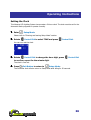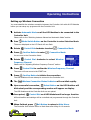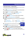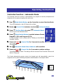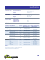
1
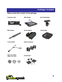
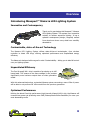
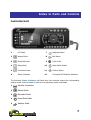
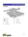
LED Lighting System
P-Series Owner’s Manual
Innovative, efficient and versatile.
Dear Customer,
Thank you for purchasing this product.
For optimum performance and safety, please read these instructions carefully.
User Memo:
Date of purchase:
Dealer name:
Dealer address:
Dealer website:
Dealer email:
Dealer phone no.:
Product:
Controller Unit
LED Module
Mounting Frame Set
Power Supply Unit
Please visit us on facebook or twitter!
https://www.facebook.com/pages/Maxspect-LED/283406251689606
http://twitter.com/maxspectled
1
Table of Content
Introducing Maxspect™ Mazarra LED Lighting System ............................................ 6
Innovative and Contemporary ............................................................................ 6
Customizable, state-of-the-art Technology .......................................................... 6
Unparalleled Efficiency ...................................................................................... 6
Optimized Performance ..................................................................................... 6
Controller Unit ..................................................................................................... 7
LED Module ......................................................................................................... 8
Mounting the Mazarra LED Lighting System ........................................................... 9
Powering the Mazarra LED Lighting System ......................................................... 14
Optics ............................................................................................................... 15
Installing / Changing Optics ............................................................................. 16
Passive / Active Cooling ...................................................................................... 17
Installing the Optional Fan ............................................................................... 17
Changing / Replacing LED Bulbs ......................................................................... 18
The LED Module ................................................................................................ 19
Switching between Standalone and Connected Mode ........................................ 19
LED Module Status .......................................................................................... 19
LED Module – Standalone Mode .......................................................................... 20
Turning on the LED Channels ........................................................................... 20
Control the LED Module in Standalone Mode ..................................................... 20
LED Module – Connected Mode ........................................................................... 21
Connecting LED Modules to the Controller Unit ................................................. 21
Adjusting the LED Sequence Number ............................................................... 22
Adjusting Wireless Frequency Channel.............................................................. 23
Adjusting Active Cooling Setting ....................................................................... 24
The Controller Unit ............................................................................................. 25
Turning on the Controller Unit .......................................................................... 25
Entering and leaving Setup Mode ..................................................................... 25
Setting the Clock ............................................................................................. 26
Setting up Wireless Connection ........................................................................ 27
Controller Function – Manual Mode ..................................................................... 28
Controller Function – Automatic Mode ................................................................. 29
Controller Function – Photoperiod Programs ........................................................ 30
Understanding Time Points .............................................................................. 30
Programming Time Points ................................................................................ 30
Controller Function – Setting up Moon Light ........................................................ 31
Controller Function – Dawn/Dusk Mode ............................................................... 32
Setting Dawn/Dusk Mode ................................................................................ 32
Controller Function – Weather Mode ................................................................... 34
Setting Weather Mode ..................................................................................... 34
2
Package Content
Please check the content in the package.
Controller Unit
LED Module
Ball Joint Mount
Rail System
Power Supply
Cooling Fan
T-Joint Cable
Cable Organizer
Optic Lens Sets
(100°/70°/40°)
Accessories
3
Precautions
Before using this Maxspect™ Mazarra LED Lighting System please read
these operating instructions carefully. Take special care to follow the safety
suggestions listed below.
Afterwards keep this manual handy for future reference.
Before using the Maxspect™ Mazarra LED Lighting System
1.
2.
Remove any protective film covering the lens of the LED bulbs before use.
Never look directly at the LED bulbs when you switch on the system. Incorrect use of this
apparatus will increase eye hazard.
On Safety
1.
2.
3.
Power Source – Do not defeat the safety purpose of the polarized or grounding-type
plug. A polarized plug has two blades with one wider than the other. A grounding-type
plug has two blades and a third grounding prong. The wide blade or the third prong are
provided for your safety. If the plug does not fit into your outlet, consult an electrician for
replacement of the obsolete outlet.
Power Cord Protection – The power supply cords should be routed so that they are not
likely to be walked on or pinched by items placed upon or against them. Never take hold
of the plug or cord if your hand is wet, and always grasp the plug body when connecting
or disconnecting it.
Installation – Install indoor only, and use the attachments, mounting frames, hanging
kit and accessories provided and specified by the manufacturer.
On Operation
1.
2.
3.
4.
5.
6.
Operation – Always follow the operation instructions set forth in this manual when using
this Mazarra LED Lighting System.
Heat – The apparatus should be situated away from heat sources such as radiators, and
do not expose to excessive heat such as sunshine, fire or the like.
Moisture – To reduce the risk of fire or electric shock, do not expose this apparatus to
rain, moisture, dripping or splashing.
Ventilation – The apparatus should be situated so that its location or position does not
interfere with its proper ventilation.
Magnetism – The apparatus should be situated away from equipment or devices that
generate strong magnetism.
Cleaning – Clean only with dry cloth.
4
Warning
Notice for customers in the United States
This equipment has been tested and found to comply with the limits for a Class B digital device,
pursuant to Part 15 of the FCC Rules. These limits are designed to provide reasonable
protection against harmful interference in residential installation. This equipment generates,
uses, and can radiate radio frequency energy and, if not installed and used in accordance with
the instructions, may cause harmful interference to radio communications. However, there is
no guarantee that interference will not occur in a particular installation. If this equipment does
cause harmful interference to radio or television reception, which can be determined by
turning the equipment off and on, the user is encouraged to try to correct the interference by
one or more of the following measures:
Switch the master channel on the controller to another channel.
Increase the separation between the equipment and receiver.
Connect the equipment into an outlet on a circuit different from that to which the receiver
is connected.
Consult the dealer or an experienced radio/TV technician for help.
THIS CLASS B DIGITAL DEVICE COMLIES WITH PART 15 OF THE FCC RULES OPERATION IS
SUBJECT TO THE FOLLOWING TWO CONDITIONS: (1) THIS DEVICE MAY NOT CAUSE
HARMFUL INTERFERENCE, AND (2) THIS DEVICE MUST ACCEPT ANY INTERFERENCE
RECEIVED, INCLUDING INTERFERENCE THAT MAY CAUSE UNDESIRED OPERATION.
This equipment complies with the FCC radiation exposure limits set forth for uncontrolled
equipment and meets FCC Radio Frequency (RF) Exposure Guidelines in Supplement C to
OET65. This equipment should be installed and operated with at least 20cm and more
between the radiator and person’s body (excluding extremities: hands, wrists, feet and
ankles).
Notice for customers in Canada
This Class B digital apparatus complies with Canadian ICES-003.
This device complies with RSS-Gen of IC Rules.
Operation is subject to the following two conditions: (1) this device may not cause
interference, and (2) this device must accept any interference, including interference that may
cause undesired operation of this device.
This equipment complies with the IC radiation exposure limits set forth for uncontrolled
equipment and meets RSS-102 of the IC Radio Frequency (RF) Exposure rules. This
equipment should be installed and operated with at least 20cm and more between the radiator
and person’s body (excluding extremities: hands, wrists, feet and ankles).
5
Overview
Introducing Maxspect™ Mazarra LED Lighting System
Innovative and Contemporary
Thank you for purchasing this Maxspect™ Mazarra
LED Lighting System. This system is an innovative
solution to modern aquarium lighting. It has a
splendid contemporary design, elegantly crafted
from aluminum where every detail was carefully
attended to.
Customizable, state-of-the-art Technology
The Mazarra LED Lighting System utilizes state-of-the-art technologies, from wireless
controller to latest LED chips, offering optimized performance and unparalleled energy
efficiency.
The Mazarra is designed with one goal in mind: Customizability – letting you to take full control
over you lighting system.
Unparalleled Efficiency
The Cree XLamp® XM-L chip is capable of producing up to 180
lumen/watt. This means at the same wattage it can produce
significantly more luminous output than an older generation
model.
With this advanced technology, a standard Mazarra system consuming a mere 120w of power
will be able to out-perform the 160w model from the previous generation.
Optimized Performance
Utilizing the latest Cree high performance high intensity XLamp® XM-L chip, the Mazarra will
consume less power yet producing more PAR (Photosynthetic Active Radiation) for even your
most demanding corals.
6
Index to Parts and Controls
Controller Unit
6
1
2
8
7
3
10
4
9
11
5
12
1
LCD Panel
7
Backlight Button
2
Manual Mode
8
Exit Button
3
Automatic Mode
9
Control Dial
4
Setup Mode
10
Mode Switch Button
5
Connection Mode
11
Confirm Button
6
Status Indicators
12
Connected LED Modules Indicators
The following Status Indicators will flash when the controller enters the corresponding
settings mode, and will remain lit when the corresponding mode is activated.
1
Wireless Connection
2
Manual Mode
3
Automatic Mode
4
Dawn/Dusk Mode
5
Weather Mode
7
Index to Parts and Controls
LED Module
1
Select Button
6
Rail System
2
Control Dial
7
Rail Connector
3
LCD Display
8
Cable Organizer
4
Thumb Screw
9
Power Supply Cable
5
Ball Joint Mount
8
Installation
Mounting the Mazarra LED Lighting System
Before connecting the LED Modules to the Controller Unit, first mount the system by using the
provided Frame Set.
1.
Assemble the Frame Set.
Assemble the frame set by connecting sections together to form a secured structure, as
illustrated in the following diagrams.
Note
Standard Frame Set Packages are illustrated below:
9
Installation
2.
Pendant Mounting
For a single row configuration, you can assemble the frame set as illustrated below:
For multiple-row configuration, you can assemble the frame set as illustrated below:
3.
Mounting inside the Canopy
You can mount the system onto the top of your canopy as illustrated below:
10
Installation
4.
Mounting on Cabinet / Stand
You can mount the system on the cabinet / stand of your aquarium as illustrated below.
5.
Mounting on Wall
You can mount the system on wall as illustrated below.
11
Installation
6.
Mounting on Aquarium
You can mount the system on your aquarium by resting the frame on the glass/acrylic
panels as illustrated below.
12
Installation
Note
The maximum width of the glass/acrylic the stand can fit onto is 20mm (3/4”). The stand can
be mounted on top of the glass/acrylic panel or sideway on support beams found on larger
aquariums.
7.
Mounting and positioning the LED Lighting System
Depends on the dimensions of your aquarium, there are many different configurations
you could mount and position the Mazarra LED Lighting System.
13
Installation
Powering the Mazarra LED Lighting System
A sample connection configuration utilizing 2 LED Modules
1.
Each Power Supply can power up to 2 LED Modules and 1 Controller
Unit.
2.
For additional LED Modules, you must connect more Power Supplies.
WARNING: Use only Maxspect™ Mazarra P-Series Power Supply for P-Series LED Modules.
Do not connect more more than 2 LED Modules to one Power Supply as doing so may cause
damage to the Power Supply!!
14
Installation
Optics
Each Mazarra LED Module comes with three sets of optics, ranges from 100°, 70° to 40°
(factory default is 100°). Installing optics will enhance penetration of light over a greater
depth of water by converging light from the LED bulbs, but at the same time reducing the
coverage area.
By mix-and-matching different types of optics to be installed, you would be able to customize
the overall appearance and performance of your Mazarra LED Lighting System.
Note
You must install one of the three types of optics on every bulb. The optics also serves as a
protective barrier that prevents water and moisture from damaging the LED bulbs.
WARNING: Installing the 40° optics will converge light into a narrow beam, incorrect usage
of optics may result in bleaching of your corals from over-exposure to high intensity light.
15
Installation
Installing / Changing Optics
1.
Using a small slotted screwdriver, carefully remove the screws on the
bottom panel and remove it.
2.
Push the optics out of the bottom panel.
3.
Place the new optics over the slot and apply pressure on it until you
hear it snaps.
16
Installation
Passive / Active Cooling
With the new Cree XLamp® XM-L chip, higher efficiency
means less power is consumed and the Mazarra runs cooler
than its predecessors. Together with an ingenious
aerodynamic design, the Mazarra is passively cooled when
warm air passes through its aluminum chassis.
Nonetheless, in the situation where you do need to actively
cool your LED Module, for example, your Mazarra is installed
in a confined space such as a canopy, you can install the
optional fan by following the below instructions.
Note
The fan is temperature controlled, it will only turn on when the temperature rises above a
preset value (see Operating Instructions on the LED Module and Controller Unit). Installing the
optional fan will ensure the module runs at optimal temperature and prolong the lifespan of
LED Bulbs.
Installing the Optional Fan
1.
Insert the fan onto the slot as indicated by the diagram below, and
connect the power cable.
17
Maintenance
Changing / Replacing LED Bulbs
The Mazarra is the only LED Lighting System available on the market that offers both
plug-and-play LED bulb replacement design and LED bulbs covering the entire color spectrum,
allowing maximum customization and flexibility.
By mix-and-matching colored LED bulbs, Mazarra allows you to pick the right color spectrum
for your aquarium, and bring out that color from your corals exactly like you have always
dreamed of.
WARNING: Install only Maxspect™ LED Bulbs onto Mazarra LED Modules. Installing
unauthorized or aftermarket LED Bulbs onto Mazarra LED Modules will void your warranty!!
WARNING: Prior to installing LED Bulbs, you must ensure you are using the correct wattage
and driving current for the LED Bulb. Using a wrong wattage and/or driving current could
shorten the lifespan of bulb or even damage it!!
1.
Open the LED Module the same way as you would replace Optics.
Please refer to “Installing / Changing Optics” section for detail instructions.
2.
Carefully loosen and remove the screws, then lift the clasp holding the
LED Bulb chip to replace it.
3.
When finished, return the clasp to its original position and tighten the
screws.
18
Operating Instructions
The LED Module
Follow the instructions below to operate and program the LED Module.
Note
The LED Module turns on automatically when power is connected, and
turns off when power is cut.
When power is resumed, the LED Module will restore to the previous saved setting
automatically, whether it was last set at Standalone Mode or Connected Mode, and the
intensity level of all the LED channels.
Switching between Standalone and Connected Mode
1.
Press and hold
Select Button for 2 seconds to switch between
Standalone Mode and Connected Mode.
2.
Press
Control Dial to turn on the backlight on the LCD Display.
The backlight will turn off automatically after 30 seconds of idling.
LED Module Status
1.
Intensity of the 4 LED channels, temperature of the LED Module and
status of the fan will be shown on the LCD Display.
2.
The status of the LED Module will rotate every 5 seconds.
19
Operating Instructions
LED Module – Standalone Mode
You may only need to enter Standalone Mode if you’re using the P-Series Mazarra
without a Controller Unit. In Standalone Mode, you can adjust the intensity of the 4 LED
channels and Active Cooling setting directly from the LED Module.
Turning on the LED Channels
1.
Press
Select Button to turn on all 4 LED channels simultaneously.
2.
Press
Select Button the button again to turn them off.
Control the LED Module in Standalone Mode
1.
Press and hold
Control Dial for 3 seconds to enter setup. Channel A
will be selected first.
2.
To adjust brightness of the selected channel, rotate
Control Dial.
Rotate clockwise will increase the brightness and vice versa.
3.
Press
Control Dial to switch to the next LED channel. Repeat #2 for
channel B, C and D.
4.
Press
Control Dial again to adjust the Active Cooling setting.
Active Cooling means the minimum temperature the LED Module must reach before the
fan will be turned on automatically.
5.
To adjust the temperature, rotate
Control Dial.
There are 5 settings: 40°C/104°F, 45°C/113°F, 50°C/122°F, 55°C/131°F and 60°C/140°F.
6.
When finished, press and hold
Control Dial to save the setting.
The setting is now saved. The setting will also be saved after idling for 30 seconds.
20
Operating Instructions
LED Module – Connected Mode
In Connected Mode, the Controller Unit will take command over the LED Modules.
However you must first connect the LED Modules to the Controller Unit.
Connecting LED Modules to the Controller Unit
See the connection diagrams below, and read the additional information to properly connect
the Mazarra LED Lighting System.
A sample connection configuration utilizing 1 Controller Unit.
1.
Each Controller Unit can connect up to 16 LED Modules through wireless
connection.
If you have more than 16 LED Modules, you must use another Controller Unit.
2.
There is a maximum of 16 wireless frequencies.
Therefore you can install up to a maximum of 16 Controller Units in 10 meters (33 feet)
radius. Please refer to “Adjusting Wireless Frequency Channel” section for detail
instructions.
21
Operating Instructions
Adjusting the LED Sequence Number
The LED Sequence Number must be assigned for Dawn/Dusk Mode and Weather Mode
programs to execute properly.
A sample wireless connection setting utilizing 16 LED Modules assigned to 8 groups.
1.
Press and hold
2.
The first screen is the LED Sequence Number screen.
3.
Rotate
4.
Press
5.
When finished, press and hold
Control Dial for 3 seconds to enter setup.
Control Dial to select the desired LED Sequence Number.
Select Button to confirm the setting.
Control Dial to save the setting.
The setting is now saved. The setting will also be saved after idling for 30 seconds.
22
Operating Instructions
Adjusting Wireless Frequency Channel
Note
You only need to adjust the Wireless Frequency Channel if you have more than 1 Controller
Unit within 10 meters (33 feet) radius, as Controller Units operating on the same Wireless
Frequency Channel will interfere with each other.
1.
Press and hold
2.
Press
Control Dial for 3 seconds to enter setup.
Control Dial once to select the Wireless Frequency Channel
screen.
3.
Rotate
Control Dial to select the desired Wireless Frequency
Channel.
4.
Press
5.
When finished, press and hold
Select Button to confirm the setting.
Control Dial to save the setting.
The setting is now saved. The setting will also be saved after idling for 30 seconds.
23
Operating Instructions
Adjusting Active Cooling Setting
1.
Active Cooling means the minimum temperature the LED Module must
reach before the fan will be turned on automatically.
2.
Press and hold
3.
Press
4.
To adjust the temperature, rotate
Control Dial for 3 seconds to enter setup.
Control Dial twice to select the Active Cooling setting screen.
Control Dial.
There are 5 temperature settings: 40°C/104°F, 45°C/113°F, 50°C/122°F, 55°C/131°F and
60°C/140°F.
5.
When finished, press and hold
Control Dial to save the setting.
The setting is now saved. The setting will also be saved after idling for 30 seconds.
24
Operating Instructions
The Controller Unit
Follow the instructions below to operate and program the Controller Unit.
Turning on the Controller Unit
1.
The Controller Unit turns on automatically when power is connected,
and turns off when power is cut.
The Controller will remember its previous setting, whether it was last set at Manual Mode
or Automatic Mode.
2.
Press
Backlight Button on the Controller Unit.
The LCD Panel backlight turns on, and will turn off automatically after 30 seconds of idling.
The backlight will remain lit when the Controller Unit is in the Setup Mode or Connection
Mode.
Entering and leaving Setup Mode
You will need to enter Setup Mode to adjust settings and setup programs.
1.
Press
Mode Switch Button on the Controller to enter Selection Mode.
The arrow displayed on the LCD Panel will now flash.
2.
Rotate
3.
Press
Control Dial clockwise to select
Confirm Button to enter
Setup Mode.
Setup Mode.
You are now in the Setup Mode.
4.
When finished, press
Exit Button to return to Main Menu.
The Controller Unit will also return to Main Menu after idling for 10 seconds.
25
Operating Instructions
Setting the Clock
This Mazarra LED Lighting System incorporates a 24-hour clock. The clock must be set for the
Automatic Mode programs to operate correctly.
1.
Enter
Setup Mode.
Please refer to “Entering and leaving Setup Mode” section.
2.
Rotate
Control Dial to select TIME and press
Control Dial.
You can now set the clock.
3.
Rotate
Control Dial to change the hour digit, press
Control Dial
to confirm, repeat for the minute digit.
The clock is now set.
4.
Press
Exit Button to return to
Setup Mode.
The Controller Unit will also return to Setup Mode after idling for 30 seconds.
26
Operating Instructions
Setting up Wireless Connection
You must establish the wireless connection between the Controller Unit with all LED Modules
before you can setup any programs with the Controller Unit.
1.
Activate Automatic Mode on all the LED Modules to be connected to the
Controller Unit.
Please refer to the “Switching between Manual and Automatic Mode” section.
2.
Press
Mode Switch Button on the Controller to enter Selection Mode.
The arrow displayed on the LCD Panel will now flash.
3.
Rotate
4.
Press
Control Dial clockwise to select
Confirm Button to enter
Connection Mode.
Connection Mode.
You are now in the Connection Mode.
5.
Rotate
Control Dial clockwise to select Wireless
Frequency Channel.
Please refer to “Adjusting Wireless Frequency Channel” section.
6.
Press
Control Dial to confirm the Wireless Frequency Channel.
The cursor will now move to the START box.
7.
Press
Confirm Button to initiate the connection.
The LED Modules will now attempt to connect to the Controller Unit.
8.
The
9.
Upon successful connection,
Wireless Connection Status Indicator will now blink rapidly.
Select Button on the LED Modules will
blink slowly and the corresponding number will appear on display.
The LED Modules and the Controller Unit are now paired.
10. Once paired,
Control Dial on all LED Modules will no longer function.
All functionalities and settings will be controlled and programmed through the Controller
Unit.
11.
When finished, press
Exit Button to return to Main Menu.
The Controller Unit will also return to Main Menu after idling for 10 seconds.
27
Operating Instructions
Controller Function – Manual Mode
There are a total of 4 LED channels on each connected LED Module, the Controller Unit allows
you to manually turn them on, off and adjust their brightness.
1.
Press
Mode Switch Button on the Controller to enter Selection Mode.
The arrow displayed on the LCD Panel will now flash.
2.
Rotate
3.
Press
Control Dial clockwise to select
Confirm Button to enter
Manual Mode.
Manual Mode.
You are now in the Manual Mode.
4.
Press and hold
5.
The
6.
Press the following buttons to turn on or turn off the corresponding LED
Control Dial for 3 seconds to modify the settings.
Manual Mode Status Indicator will now blink.
channel.
7.
Backlight Button
Channel A
Exit Button
Channel B
Mode Switch Button
Channel C
Confirm Button
Channel D
To adjust brightness of the selected channel, rotate
Control Dial.
Rotate clockwise will increase the brightness and vice versa.
8.
Press
Control Dial to advance to the next LED channel, and repeat
#6 until the desired brightness of all 4 LED channels is set.
9.
Press and hold
Control Dial for 3 seconds to confirm settings.
The settings are now saved. The settings will also be saved if the Controller Unit was left
idle for 30 seconds.
28
Operating Instructions
Controller Function – Automatic Mode
The Controller Unit can be setup to automatically run programs to control photoperiod and
brightness of the system throughout the entire day.
1.
Press
Mode Switch Button on the Controller to enter Selection Mode.
The arrow displayed on the LCD Panel will now flash.
2.
Rotate
3.
Press
Control Dial clockwise to select
Confirm Button to enter
Automatic Mode.
Automatic Mode.
You are now in the Automatic Mode.
4.
Press
Mode Switch Button to switch between Preset,
Program 1 (P1) and Program 2 (P2).
To setup Program 1 and 2, please refer to “Setting up User-Defined
Programs” section.
5.
Press and hold
Control Dial for 3 seconds to modify
the settings.
6.
The
7.
Press and hold
Automatic Mode Status Indicator will now blink.
Control Dial for 3 seconds to confirm settings.
The settings are now saved. The settings will also be saved if the Controller Unit was left
idle for 30 seconds.
The Preset photoperiod program cannot be changed and will automatically control the
brightness of the system following the pattern demonstrated in the diagram below.
100%
50%
Channel A
10:00pm
Channel D
8:00pm
6:00pm
Channel C
4:00pm
2:00pm
12:00pm
Channel B
10:00am
9:00am
8:00am
0%
29
Operating Instructions
Controller Function – Photoperiod Programs
The Controller Unit can be programmed to control the photoperiod and brightness of the
system throughout the day. There are a total of 2 user-definable programs that can be stored
in the system.
Understanding Time Points
There are a total of 8 Time Points for each program. You can program different luminous
output intensity at each Time Point to control the photoperiod and brightness of the system.
For example, the following table demonstrates how you could program the Time Points such
that the system would increases light gradually from 10:00am, peaks at 4:00pm then slowly
decreases light until it is turned off at 11:00pm.
TP1
TP2
TP3
TP4
TP5
TP6
TP7
TP8
11:00
13:00
14:00
16:00
19:00
20:00
22:00
23:00
Channel A
20%
40%
80%
100%
80%
40%
20%
1%
Channel B
OFF
20%
60%
100%
60%
20%
OFF
OFF
Channel C
20%
40%
60%
80%
60%
40%
20%
1%
Channel D
10%
30%
60%
90%
60%
30%
10%
OFF
The following diagram would illustrate how the 4 LED channels would behave once the above
Time Points have been programmed.
100%
50%
Channel A
Channel B
Channel C
Channel D
12:00am
10:00pm
8:00pm
6:00pm
4:00pm
2:00pm
12:00pm
10:00am
0%
Programming Time Points
1.
Enter
Setup Mode.
Please refer to “Entering and leaving Setup Mode” section
30
Operating Instructions
2.
Rotate
Control Dial to select PROGRAM 1 and press
Control Dial.
You can now setup Program 1.
3.
Press
4.
Rotate
Mode Switch Button to switch between the 8 Time Points.
Control Dial to select ON/OFF.
This will activate or deactivate this Time Point. When a Time Point has been deactivated,
the settings associated with this Time Point will be ignored, but not deleted. You could use
this feature to quickly alter your photoperiod without having to reprogram the settings.
5.
Press
Control Dial to switch to the timer, rotate
Control Dial to
change it.
The timer will increment/decrement in 30-minutes intervals. Note: Changes you made to
a Time Point will affect all subsequence Time Points to prevent erroneous behavior. For
example, if you change the timer to a larger value than the next Time Point, the system
will push the next Time Point to the same time, with a maximum value of 23:30.
6.
Press
7.
Rotate
Control Dial to switch to Channel A.
Control Dial to adjust brightness for this channel then press
Control Dial to switch to the next channel.
Repeat #6 and #7 for all 4 channels. Note: At 0% intensity the channel is turned OFF.
8.
Repeat #3 to #8 for all 8 Time Points.
9.
Press
Exit Button to confirm and return to Setup Mode.
The settings are now saved. The settings will also be saved if the Controller Unit was left
idle for 30 seconds.
10. To setup PROGRAM 2, perform #2 but select PROGRAM 2, then repeat
the above steps.
Controller Function – Setting up Moon Light
Moon-Light can be programmed into Program 1 or 2 by simply assign one or more of the LED
channels (preferably the blue LED channel) to operate at 1% brightness in the last Time Point.
31
Operating Instructions
Controller Function – Dawn/Dusk Mode
The Mazarra LED Lighting System has a built-in Dawn/Dusk Mode. The Dawn/Dusk Mode will
simulate the effect of the sun slowly rises and sets over the horizon.
To demonstrate how the Dawn/Dusk Mode works, the
following diagrams will illustrate a sample Dawn/Dusk
Mode behavior utilizing 4 LED Modules in a row
pattern configuration, as shown in the photo to the
right.
Dawn Mode:
Dusk Mode:
Setting Dawn/Dusk Mode
1.
Enter
Setup Mode.
Please refer to “Entering and leaving Setup Mode” section
2.
Rotate
Control Dial to select DAWN/DUSK and press
Control
Dial.
You can now setup Dawn/Dusk Mode.
32
Operating Instructions
3.
Press
Control Dial to switch between ON and OFF.
Select ON to turn on Dawn/Dusk Mode, OFF to turn it off.
4.
Select ON to turn on Dawn/Dusk Mode; select OFF to turn it off.
5.
Press
6.
Rotate
7.
Press
Control Dial to switch to the delay timer.
Control Dial to adjust the delay timer in 5-minutes intervals.
Exit Button to confirm and return to Setup Mode.
The settings are now saved. The settings will also be saved if the Controller Unit was left
idle for 30 seconds.
33
Operating Instructions
Controller Function – Weather Mode
The Mazarra LED Lighting System has a built-in Weather Mode. The Weather mode will
simulate the effect of clouds slowly moving across the sky, casting shadows over the ocean.
The following diagram illustrates the amount of sunlight received near the surface of the
ocean, on a typical sunny day.
120.00%
100.00%
80.00%
60.00%
40.00%
20.00%
7:
00
:
7: 00
45
:
8: 00
30
:
9: 00
15
10 :00
:0
0
10 :00
:4
5
11 :00
:3
0
12 :00
:1
5
13 :00
:0
0
13 :00
:4
5
14 :00
:3
0
15 :00
:1
5
16 :00
:0
0
16 :00
:4
5
17 :00
:3
0:
00
0.00%
As clouds slowly move across the sky, casting shadow over the ocean, the amount of sunlight
received near the surface of the ocean dramatically reduced. By changing different parameters
such as thickness of clouds and the speed they move at, you can program your Mazarra LED
Lighting System to simulate any given day as sunny, cloudy, windy, overcast or rainy.
Setting Weather Mode
1.
Enter
Setup Mode.
Please refer to “Entering and leaving Setup Mode” section
2.
Rotate
Control Dial to select WEATHER and press
Control Dial.
You can now setup Weather Mode.
34
Operating Instructions
3.
Press
Control Dial to switch between ON and OFF.
Select ON to turn on Weather Mode, OFF to turn it off.
4.
Press
5.
Rotate
6.
Press
Control Dial to enter Weather SETUP Mode
Control Dial to switch between SUNNY, CLOUDY and RAINY.
Exit Button to confirm and return to Setup Mode.
The settings are now saved. The settings will also be saved if the Controller Unit was left idle
for 30 seconds.
The following table provides a sample Weather Mode settings for each type of weather.
Sunny
Cloudy
Rainy
Cloud Thickness
Cloud Speed
THIN
THIN
THICK
SLOW
FAST
FAST
35
Troubleshooting
The Controller Unit and/or the LED Module do not turn on.
Check to see if the power supply has been connected to the outlet properly.
Check the connector cables to make sure the connection is secured.
The LED Module is very dim.
Check the brightness settings in the controller to make sure it is set properly.
Cannot adjust the brightness of the LED Modules.
Make sure the Controller Unit is in Manual Settings Mode, the Manual Mode Indicator should be
flashing when the Controller Unit is in Manual Settings Mode.
Cannot program the LED Modules.
Make sure the Controller Unit is in Automatic Settings Mode, the Automatic Mode Indicator
should be flashing when the Controller Unit is in Automatic Settings Mode.
Cannot connect LED Modules to the Controller Unit.
Make sure the Controller Unit is in Connection Settings Mode, the Connection Mode Indicator
should be flashing when the Controller Unit is in Connection Settings Mode.
Cannot setup dawn / dusk mode programs.
Make sure the Controller Unit is in Dawn/Dusk Settings Mode, the Dawn/Dusk Mode Indicator
should be flashing when the Controller Unit is in Dawn/Dusk Settings Mode.
Cannot setup weather mode programs.
Make sure the Controller Unit is in Weather Settings Mode, the Weather Mode Indicator should
be flashing when the Controller Unit is in Weather Settings Mode.
* If the problem persists after troubleshooting, please stop using this Mazarra LED Lighting System and
return it to the dealer. DO NOT attempt to service the LED Lighting System yourself – doing so will void
the warranty.
36
Limited Warranty
Maxspect Ltd. warrants all Maxspect™ Mazarra LED Lighting System products against defects
in workmanship for a period of 12-months from the date of purchase. If a defect exists during
the warranty period, Maxspect Ltd. at its option will either repair (using new or
remanufactured parts) or replace (with a new or remanufactured unit) the product at no
charge.
THE WARRANTY WILL NOT APPLY TO THE PRODUCT IF IT HAS BEEN DAMAGED BY MISUSE,
ALTERATION, ACCIDENT, IMPROPER HANDLING OR OPERATION, OR IF UNAUTHORIZED
REPAIRS ARE ATTEMPTED OR MADE. SOME EXAMPLES OF DAMAGES NOT COVERED BY
WARRANTY INCLUDE, BUT ARE NOT LIMITED TO, USING AFTER-MARKET LED BULBS AND
MODIFICATION OF THE CIRCUITRY, WHICH ARE PRESUMED TO BE DAMAGES RESULTING
FROM MISUSE OR ABUSE.
DISCLAIMER OF CONSEQUENTIAL AND INCIDENTAL DAMAGES:
You and any other user of Maxspect Ltd. products shall not be entitled to any consequential or
incidental damages, including without limitation, loss of use of the unit, inconvenience,
damage to personal property, phone calls, lost income or earnings. This warranty gives you
specific legal rights and you may also have other rights, which vary from state to state.
MAXSPECT LTD. MAKES NO WARRANTY OR REPRESENTATION, EITHER EXPRESS OR
IMPLIED, WITH RESPECT TO THE PRODUCT'S QUALITY, PERFORMANCE, MERCHANTABILITY,
OR FITNESS FOR A PARTICULAR PURPOSE. AS A RESULT, THIS PRODUCT, IS SOLD "AS IS,"
AND YOU THE PURCHASER ASSUME THE ENTIRE RISK AS TO ITS QUALITY AND
PERFORMANCE.
IN NO EVENT WILL MAXSPECT LTD BE LIABLE FOR DIRECT, INDIRECT, SPECIAL,
INCIDENTAL, OR CONSEQUENTIAL DAMAGES RESULTING FROM ANY DEFECT IN THE
PRODUCT OR ITS DOCUMENTATION.
The warranty, disclaimer, and remedies set forth above are exclusive and replace all others,
oral or written, expressed or implied. At no time will any Maxspect Ltd. dealers, agents, or
employees be authorized to make any modifications, extension, or addition to this warranty.
Some states do not allow the exclusion or limitation of implied warranties or liability for
incidental or consequential damages, so the above limitation or exclusion may not apply to
you.
37
Specifications
Controller Unit
Dimensions (D x L)
Φ120mm × 60mm x 30mm
(4.7” x 2.4” x 1.2”)
LED Module
Weight
300g (10 oz)
Dimensions (D x L)
Φ230mm × 230mm x 35mm
(9” x 9” x 1.5”)
Power Supply
Weight
2kg (4.4 lb)
Input Voltage
Output Voltage
Output Current
AC 100 - 240V / 50 - 60 Hz
18V
10A
LED Bulbs
Channel Make/Model
A
Quantity Luminous Flux & Color Temperature
Driven Current
/ Wavelength
Cree XLamp® XM-L
T6
Philips Luxeon Rebel
B
LXML-PB01-0040
Philips Luxeon Rebel
LXML-PR01-0500
Philips Luxeon Rebel
C
LXML-PB01-0040
Philips Luxeon Rebel
LXML-PR01-0500
D
Cree XP-G
Q3
SiBDI
S35-U U60
SiBDI
S35-U U70
4
540 lm @ 1500mA
2
88 lm @ 1000mA
2
1222mW @ 1000mA
2
88 lm @ 1000mA
2
1222mW @ 1000mA
2
232 lm @ 1000mA
1
500mW @ 1000mA
1
600mW @ 1000mA
Cool White
7000-8000K
Blue
460-490nm
Royal Blue
440-460nm
Blue
460-490nm
Royal Blue
440-460nm
CRI 85 Warm White
3000K
Super Actinic
400-410nm
Super Actinic
410-420nm
Note:
Specifications are subject to change without notice.
Weight and dimensions are approximate.
38
Maxspect. Innovative, efficient and versatile.
Maxspect Limited
www.maxspect.com
NOTE: Products, packaging, features and specifications are subject to change.
All screen images are simulated.
© 2009-2011 Maxspect Limited. Reproduction in whole or in part without written
permission is prohibited. All rights reserved. Maxspect and Mazarra are trademarks
of Maxspect Limited. Cree and XLamp are trademarks of Cree, Inc. Bridgelux is
trademark of Bridgelux, Inc. Philips and Luxeon Rebels are trademarks of Philips
Lumileds Lighting Company.
Owner’s Manual Version 1.5.0
39